WO2019011168A1 - Dispositif électronique, et procédé de communication sans fil - Google Patents
Dispositif électronique, et procédé de communication sans fil Download PDFInfo
- Publication number
- WO2019011168A1 WO2019011168A1 PCT/CN2018/094454 CN2018094454W WO2019011168A1 WO 2019011168 A1 WO2019011168 A1 WO 2019011168A1 CN 2018094454 W CN2018094454 W CN 2018094454W WO 2019011168 A1 WO2019011168 A1 WO 2019011168A1
- Authority
- WO
- WIPO (PCT)
- Prior art keywords
- time interval
- transmission time
- electronic device
- user equipment
- subframe
- Prior art date
Links
- 238000004891 communication Methods 0.000 title claims abstract description 143
- 238000000034 method Methods 0.000 title claims abstract description 33
- 230000005540 biological transmission Effects 0.000 claims abstract description 194
- 238000012545 processing Methods 0.000 claims abstract description 53
- 230000011664 signaling Effects 0.000 claims description 52
- 230000007246 mechanism Effects 0.000 description 20
- 230000006870 function Effects 0.000 description 19
- 238000010586 diagram Methods 0.000 description 17
- 230000008569 process Effects 0.000 description 13
- 230000001960 triggered effect Effects 0.000 description 10
- 238000005259 measurement Methods 0.000 description 9
- 238000005516 engineering process Methods 0.000 description 7
- 230000010267 cellular communication Effects 0.000 description 5
- 230000008859 change Effects 0.000 description 5
- 238000013467 fragmentation Methods 0.000 description 4
- 238000006062 fragmentation reaction Methods 0.000 description 4
- 239000004065 semiconductor Substances 0.000 description 4
- 238000012546 transfer Methods 0.000 description 4
- 238000013475 authorization Methods 0.000 description 3
- 230000000694 effects Effects 0.000 description 3
- 230000003287 optical effect Effects 0.000 description 3
- 238000003384 imaging method Methods 0.000 description 2
- 230000003993 interaction Effects 0.000 description 2
- 239000004973 liquid crystal related substance Substances 0.000 description 2
- 238000012986 modification Methods 0.000 description 2
- 230000004048 modification Effects 0.000 description 2
- 238000013468 resource allocation Methods 0.000 description 2
- 230000005236 sound signal Effects 0.000 description 2
- 230000001133 acceleration Effects 0.000 description 1
- 238000004458 analytical method Methods 0.000 description 1
- 238000004364 calculation method Methods 0.000 description 1
- 230000000295 complement effect Effects 0.000 description 1
- 238000004590 computer program Methods 0.000 description 1
- 239000000470 constituent Substances 0.000 description 1
- 230000010365 information processing Effects 0.000 description 1
- 230000007774 longterm Effects 0.000 description 1
- 238000007726 management method Methods 0.000 description 1
- 229910044991 metal oxide Inorganic materials 0.000 description 1
- 150000004706 metal oxides Chemical class 0.000 description 1
- 238000012544 monitoring process Methods 0.000 description 1
- 238000011160 research Methods 0.000 description 1
- 238000012216 screening Methods 0.000 description 1
- 238000011144 upstream manufacturing Methods 0.000 description 1
- 235000012431 wafers Nutrition 0.000 description 1
Images


Classifications
-
- H—ELECTRICITY
- H04—ELECTRIC COMMUNICATION TECHNIQUE
- H04W—WIRELESS COMMUNICATION NETWORKS
- H04W24/00—Supervisory, monitoring or testing arrangements
-
- H—ELECTRICITY
- H04—ELECTRIC COMMUNICATION TECHNIQUE
- H04W—WIRELESS COMMUNICATION NETWORKS
- H04W72/00—Local resource management
- H04W72/12—Wireless traffic scheduling
- H04W72/121—Wireless traffic scheduling for groups of terminals or users
-
- H—ELECTRICITY
- H04—ELECTRIC COMMUNICATION TECHNIQUE
- H04W—WIRELESS COMMUNICATION NETWORKS
- H04W72/00—Local resource management
- H04W72/04—Wireless resource allocation
- H04W72/044—Wireless resource allocation based on the type of the allocated resource
- H04W72/0446—Resources in time domain, e.g. slots or frames
-
- H—ELECTRICITY
- H04—ELECTRIC COMMUNICATION TECHNIQUE
- H04B—TRANSMISSION
- H04B17/00—Monitoring; Testing
- H04B17/30—Monitoring; Testing of propagation channels
- H04B17/309—Measuring or estimating channel quality parameters
- H04B17/318—Received signal strength
-
- H—ELECTRICITY
- H04—ELECTRIC COMMUNICATION TECHNIQUE
- H04L—TRANSMISSION OF DIGITAL INFORMATION, e.g. TELEGRAPHIC COMMUNICATION
- H04L1/00—Arrangements for detecting or preventing errors in the information received
- H04L1/0001—Systems modifying transmission characteristics according to link quality, e.g. power backoff
- H04L1/0023—Systems modifying transmission characteristics according to link quality, e.g. power backoff characterised by the signalling
-
- H—ELECTRICITY
- H04—ELECTRIC COMMUNICATION TECHNIQUE
- H04L—TRANSMISSION OF DIGITAL INFORMATION, e.g. TELEGRAPHIC COMMUNICATION
- H04L5/00—Arrangements affording multiple use of the transmission path
- H04L5/0001—Arrangements for dividing the transmission path
- H04L5/0003—Two-dimensional division
- H04L5/0005—Time-frequency
- H04L5/0007—Time-frequency the frequencies being orthogonal, e.g. OFDM(A), DMT
-
- H—ELECTRICITY
- H04—ELECTRIC COMMUNICATION TECHNIQUE
- H04L—TRANSMISSION OF DIGITAL INFORMATION, e.g. TELEGRAPHIC COMMUNICATION
- H04L5/00—Arrangements affording multiple use of the transmission path
- H04L5/003—Arrangements for allocating sub-channels of the transmission path
- H04L5/0037—Inter-user or inter-terminal allocation
-
- H—ELECTRICITY
- H04—ELECTRIC COMMUNICATION TECHNIQUE
- H04L—TRANSMISSION OF DIGITAL INFORMATION, e.g. TELEGRAPHIC COMMUNICATION
- H04L5/00—Arrangements affording multiple use of the transmission path
- H04L5/003—Arrangements for allocating sub-channels of the transmission path
- H04L5/0044—Arrangements for allocating sub-channels of the transmission path allocation of payload
-
- H—ELECTRICITY
- H04—ELECTRIC COMMUNICATION TECHNIQUE
- H04L—TRANSMISSION OF DIGITAL INFORMATION, e.g. TELEGRAPHIC COMMUNICATION
- H04L5/00—Arrangements affording multiple use of the transmission path
- H04L5/003—Arrangements for allocating sub-channels of the transmission path
- H04L5/0053—Allocation of signaling, i.e. of overhead other than pilot signals
-
- H—ELECTRICITY
- H04—ELECTRIC COMMUNICATION TECHNIQUE
- H04L—TRANSMISSION OF DIGITAL INFORMATION, e.g. TELEGRAPHIC COMMUNICATION
- H04L5/00—Arrangements affording multiple use of the transmission path
- H04L5/003—Arrangements for allocating sub-channels of the transmission path
- H04L5/0058—Allocation criteria
- H04L5/0064—Rate requirement of the data, e.g. scalable bandwidth, data priority
-
- H—ELECTRICITY
- H04—ELECTRIC COMMUNICATION TECHNIQUE
- H04L—TRANSMISSION OF DIGITAL INFORMATION, e.g. TELEGRAPHIC COMMUNICATION
- H04L5/00—Arrangements affording multiple use of the transmission path
- H04L5/0091—Signaling for the administration of the divided path
- H04L5/0092—Indication of how the channel is divided
-
- H—ELECTRICITY
- H04—ELECTRIC COMMUNICATION TECHNIQUE
- H04L—TRANSMISSION OF DIGITAL INFORMATION, e.g. TELEGRAPHIC COMMUNICATION
- H04L67/00—Network arrangements or protocols for supporting network services or applications
- H04L67/01—Protocols
- H04L67/12—Protocols specially adapted for proprietary or special-purpose networking environments, e.g. medical networks, sensor networks, networks in vehicles or remote metering networks
-
- H—ELECTRICITY
- H04—ELECTRIC COMMUNICATION TECHNIQUE
- H04W—WIRELESS COMMUNICATION NETWORKS
- H04W4/00—Services specially adapted for wireless communication networks; Facilities therefor
- H04W4/30—Services specially adapted for particular environments, situations or purposes
- H04W4/40—Services specially adapted for particular environments, situations or purposes for vehicles, e.g. vehicle-to-pedestrians [V2P]
-
- H—ELECTRICITY
- H04—ELECTRIC COMMUNICATION TECHNIQUE
- H04W—WIRELESS COMMUNICATION NETWORKS
- H04W4/00—Services specially adapted for wireless communication networks; Facilities therefor
- H04W4/70—Services for machine-to-machine communication [M2M] or machine type communication [MTC]
-
- H—ELECTRICITY
- H04—ELECTRIC COMMUNICATION TECHNIQUE
- H04W—WIRELESS COMMUNICATION NETWORKS
- H04W4/00—Services specially adapted for wireless communication networks; Facilities therefor
- H04W4/80—Services using short range communication, e.g. near-field communication [NFC], radio-frequency identification [RFID] or low energy communication
-
- H—ELECTRICITY
- H04—ELECTRIC COMMUNICATION TECHNIQUE
- H04W—WIRELESS COMMUNICATION NETWORKS
- H04W72/00—Local resource management
- H04W72/12—Wireless traffic scheduling
- H04W72/1263—Mapping of traffic onto schedule, e.g. scheduled allocation or multiplexing of flows
-
- H—ELECTRICITY
- H04—ELECTRIC COMMUNICATION TECHNIQUE
- H04W—WIRELESS COMMUNICATION NETWORKS
- H04W72/00—Local resource management
- H04W72/12—Wireless traffic scheduling
- H04W72/1263—Mapping of traffic onto schedule, e.g. scheduled allocation or multiplexing of flows
- H04W72/1268—Mapping of traffic onto schedule, e.g. scheduled allocation or multiplexing of flows of uplink data flows
-
- H—ELECTRICITY
- H04—ELECTRIC COMMUNICATION TECHNIQUE
- H04W—WIRELESS COMMUNICATION NETWORKS
- H04W72/00—Local resource management
- H04W72/20—Control channels or signalling for resource management
-
- H—ELECTRICITY
- H04—ELECTRIC COMMUNICATION TECHNIQUE
- H04W—WIRELESS COMMUNICATION NETWORKS
- H04W72/00—Local resource management
- H04W72/50—Allocation or scheduling criteria for wireless resources
- H04W72/53—Allocation or scheduling criteria for wireless resources based on regulatory allocation policies
-
- H—ELECTRICITY
- H04—ELECTRIC COMMUNICATION TECHNIQUE
- H04W—WIRELESS COMMUNICATION NETWORKS
- H04W4/00—Services specially adapted for wireless communication networks; Facilities therefor
- H04W4/30—Services specially adapted for particular environments, situations or purposes
- H04W4/40—Services specially adapted for particular environments, situations or purposes for vehicles, e.g. vehicle-to-pedestrians [V2P]
- H04W4/44—Services specially adapted for particular environments, situations or purposes for vehicles, e.g. vehicle-to-pedestrians [V2P] for communication between vehicles and infrastructures, e.g. vehicle-to-cloud [V2C] or vehicle-to-home [V2H]
-
- H—ELECTRICITY
- H04—ELECTRIC COMMUNICATION TECHNIQUE
- H04W—WIRELESS COMMUNICATION NETWORKS
- H04W4/00—Services specially adapted for wireless communication networks; Facilities therefor
- H04W4/30—Services specially adapted for particular environments, situations or purposes
- H04W4/40—Services specially adapted for particular environments, situations or purposes for vehicles, e.g. vehicle-to-pedestrians [V2P]
- H04W4/46—Services specially adapted for particular environments, situations or purposes for vehicles, e.g. vehicle-to-pedestrians [V2P] for vehicle-to-vehicle communication [V2V]
-
- H—ELECTRICITY
- H04—ELECTRIC COMMUNICATION TECHNIQUE
- H04W—WIRELESS COMMUNICATION NETWORKS
- H04W72/00—Local resource management
- H04W72/50—Allocation or scheduling criteria for wireless resources
- H04W72/51—Allocation or scheduling criteria for wireless resources based on terminal or device properties
-
- H—ELECTRICITY
- H04—ELECTRIC COMMUNICATION TECHNIQUE
- H04W—WIRELESS COMMUNICATION NETWORKS
- H04W72/00—Local resource management
- H04W72/50—Allocation or scheduling criteria for wireless resources
- H04W72/56—Allocation or scheduling criteria for wireless resources based on priority criteria
- H04W72/566—Allocation or scheduling criteria for wireless resources based on priority criteria of the information or information source or recipient
- H04W72/569—Allocation or scheduling criteria for wireless resources based on priority criteria of the information or information source or recipient of the traffic information
-
- H—ELECTRICITY
- H04—ELECTRIC COMMUNICATION TECHNIQUE
- H04W—WIRELESS COMMUNICATION NETWORKS
- H04W88/00—Devices specially adapted for wireless communication networks, e.g. terminals, base stations or access point devices
- H04W88/02—Terminal devices
-
- H—ELECTRICITY
- H04—ELECTRIC COMMUNICATION TECHNIQUE
- H04W—WIRELESS COMMUNICATION NETWORKS
- H04W92/00—Interfaces specially adapted for wireless communication networks
- H04W92/16—Interfaces between hierarchically similar devices
- H04W92/18—Interfaces between hierarchically similar devices between terminal devices
Definitions
- the present disclosure generally relates to the field of wireless communications, and more particularly, to an electronic device for wireless communication, an electronic device on a user equipment side, and a wireless communication method.
- the PC5-based sidelink subframe in the Third Generation Partnership Project (3GPP) R14 consists of 14 Orthogonal Frequency Division Multiplexing (OFDM) symbols, including Automatic Gain Control (AGC) settings and guard intervals. (GAP) symbols, demodulation reference signal (DMRS) symbols, and data symbols.
- OFDM Orthogonal Frequency Division Multiplexing
- GAP Guard intervals.
- DMRS demodulation reference signal
- data symbols data symbols.
- PC5 operations supporting the use of short transmission time intervals (sTTI) have been proposed in view of, for example, low latency and high reliability requirements for vehicle and other equipment (V2X) services.
- the sTTI is less than the length of one subframe and can be flexibly configured as needed.
- the structure of sTTI is more suitable because of the high-speed mobility of the vehicle, the timing of the vehicle may be different, and it is difficult to obtain the instantaneous information of the vehicle.
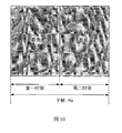
- the short-distance service communication based on the PC5 adopts the sTTI of seven symbol lengths, as shown in FIG. It is possible that only one time slot is used for transmission in a certain subframe, and in the process of sensing by the R14 user equipment, the R14 user equipment mistakenly believes that the subframe has an occupancy as shown in FIG. 10, and thus the sub-frame will be obtained. Inaccurate S-RSSI results on the frame result in inaccurate perceptual measurements.
- an electronic device for wireless communication includes processing circuitry configured to control in a case where a user equipment performs close-range traffic communication at a short transmission time interval less than a first transmission time interval So that at least two mutually independent transport blocks each having a short transmission time interval are transmitted in the same subframe, wherein the length of the subframe is the same as the first transmission time interval.
- an electronic device for wireless communication includes processing circuitry configured to: determine, in a case where a user equipment conducts close-range traffic communication at a short transmission time interval less than a first transmission time interval, Scheduling allocation signaling, the scheduling allocation signaling includes at least one scheduling allocation signaling having the same length as the first transmission time interval; and controlling to transmit at least two transmissions each having a short transmission time interval in the same subframe A block in which the length of the subframe is the same as the first transmission time interval.
- a wireless communication method includes: in a case where a user equipment performs short-range traffic communication at a short transmission time interval smaller than a first transmission time interval, such that transmissions in the same subframe each have a short transmission time interval At least two mutually independent transport blocks, wherein the length of the subframe is the same as the first transmission time interval.
- an electronic device for a user equipment side includes processing circuitry configured to: control to receive indication information from a control node; and short in the user equipment at less than a first transmission time interval In the case where the transmission time interval is for short-range traffic communication, control is performed based on the indication information such that the transport block of the user equipment is transmitted in the same subframe as another transport block having a short transmission time interval, wherein the length of the subframe is the first The transmission time interval is the same.
- an electronic device for a user equipment side includes a processing circuit configured to: control, in the case of performing short-range traffic communication at a first transmission time interval of the user equipment, to receive and Scheduling allocation signaling associated with at least two mutually independent transport blocks each having a shorter transmission time interval than the first transmission time interval transmitted in the same subframe, wherein the length of the subframe is the same as the first transmission time interval.
- the filling degree of the subframe in which the sTTI transmission occurs can be improved, thereby facilitating the solution of the problem of time resource fragmentation and/or the inaccurate measurement measurement.
- FIG. 1 is a block diagram showing a configuration example of an electronic device for wireless communication according to an embodiment of the present invention
- FIG. 2 is a block diagram showing a configuration example of an electronic device for wireless communication according to another embodiment
- FIG. 3 is a block diagram showing a configuration example of an electronic device for wireless communication according to still another embodiment
- FIG. 4 is a block diagram showing a configuration example of an electronic device for wireless communication according to an embodiment of the present invention.
- FIG. 5 is a flowchart showing an example of a procedure of a wireless communication method according to an embodiment of the present invention.
- FIG. 6 is a block diagram showing a configuration example of an electronic device for a user device side according to an embodiment of the present invention.
- FIG. 7 is a block diagram showing a configuration example of an electronic device for a user device side according to another embodiment of the present invention.
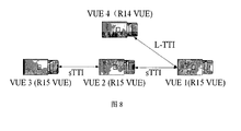
- FIG. 8 is a schematic diagram showing a case where user equipments using different transmission time intervals coexist as an example of an application scenario according to an embodiment of the present invention.
- FIG. 9 shows an example of actual occupancy of a transmission subframe of a user equipment using a short transmission time interval
- FIG. 10 is a diagram showing the occupation of the subframe shown in FIG. 9 at the perspective of a user equipment using a long transmission time interval;
- FIG. 11 is an overall flow diagram for explaining an example process performed between a base station and a user equipment, according to an example embodiment
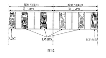
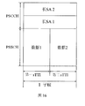
- FIG. 12 shows an example of a subframe structure in the case of pairing
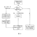
- FIG. 13 is a flowchart for explaining a pairing process according to an example embodiment
- 17 is a block diagram showing an exemplary structure of a computer that implements the method and apparatus of the present disclosure
- FIG. 18 is a block diagram showing an example of a schematic configuration of a smartphone that can apply the technology of the present disclosure
- FIG. 19 is a block diagram showing an example of a schematic configuration of an eNB (Evolved Base Station) to which the technology of the present disclosure can be applied;
- eNB Evolved Base Station
- 20 is a block diagram of an example of a schematic configuration of a car navigation device to which the technology of the present disclosure may be applied.
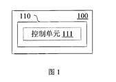
- an electronic device 100 for wireless communication includes a processing circuit 110.
- the processing circuit 110 can be implemented, for example, as a specific chip, a chipset, or a central processing unit (CPU) or the like.
- the processing circuit 110 includes a control unit 111. It should be noted that although the control unit 111 and other units are shown in the form of functional blocks in the drawings, it should be understood that the functions of the control unit 111 and other units may also be implemented by the processing circuit 110 as a whole, but not necessarily This is accomplished by processing the discrete actual components in circuit 110. In addition, although the processing circuit 110 is shown in a block in the figure, the electronic device 100 may include a plurality of processing circuits, and may distribute the functions of the control unit 111 and other units into a plurality of processing circuits, thereby being composed of a plurality of processing circuits. Work together to perform the appropriate functions.
- the control unit 111 is configured to perform control such that at least two of each having a short transmission time interval are transmitted in the same subframe in the case where the user equipment performs the short-range communication communication at a short transmission time interval smaller than the first transmission time interval A transport block independent of each other, wherein the length of the subframe is the same as the first transmission time interval.
- independent of each other refers to a transport block that will be separately transmitted in different subframes without combining, which may include transport blocks of different user equipments, and may also include the same user equipment. Transport blocks sent separately in different subframes.
- transport blocks independent of each other are separately transmitted in different subframes, and processing by the control unit 111 causes transport blocks independent of each other to be combined in the same sub-frame.
- the transmission in the frame enables the filling degree of the subframe to be improved, thereby solving the problem of fragmentation of time resources and the inaccurate measurement of the user equipment using the short transmission time interval by the user equipment using the long transmission time interval.
- the structure of the subframe in which the at least two transport blocks independent of each other are transmitted may be identical to the subframe structure of the close traffic communication at the first transmission time interval.
- the first transmission time interval (hereinafter may be referred to as TTI) may include 14 orthogonal frequency division multiplexing symbols
- the short transmission time interval (hereinafter may be referred to as sTTI) may include up to 7 orthogonal frequency division multiplexing symbol.
- the first symbol is an AGC setting
- the third, sixth, ninth, and twelfth symbols are DMRS symbols
- the fourteenth symbol is used as a guard interval.
- GAP vehicle user equipment
- the subframe includes transport blocks of two user equipments, such as vehicle user equipment (VUE) (corresponding to the first sTTI and the second sTTI, respectively).
- VUE vehicle user equipment
- the AGC is for two user equipments VUE1 and VUE2.
- the present invention is not limited to the above examples, the TTI may include any number of OFDM symbols, and the sTTI may include any number of OFDM symbols less than TTI.
- the sTTI may include any number of OFDM symbols less than TTI.
- there may be multiple sTTIs, and any number of transport blocks having the same length or different lengths of sTTI may be combined and transmitted in one subframe having the same length as the TTI, as long as the sum of the lengths of the sTTIs is not More than TTI.
- the control unit 111 can determine the transport blocks to be transmitted in the same subframe according to various ways. For example, according to one embodiment, in the case where the information to be transmitted has priority, the control unit 111 may be configured to determine a transport block to be transmitted in the same subframe based on the priority of the information to be transmitted. For example, the transport blocks corresponding to the same or close priority may be preferentially transmitted in the same subframe.
- the present invention is not limited thereto, and the combination of the transport blocks may be determined based on, for example, the amount of data of the information, the position and the moving speed of the user equipment, or the like, or may be determined randomly, for example, without considering the above factors. The combination.
- the close-range service communication may include, for example, machine type communication (MTC), device to device (D2D) communication, and vehicle and other device (V2X) communication. , Internet of Things (IOT) communications, etc.
- MTC machine type communication
- D2D device to device
- V2X vehicle and other device
- IOT Internet of Things
- the control node that determines and controls the combination of the transport blocks can be implemented on the base station side or on the user equipment side.
- the control node can also be implemented on the roadside equipment side.
- there are two V2X communication modes for example, in resource allocation, mainly including two resource allocation modes, one is base station scheduling (mode 3), and the other is UE autonomous selection (mode 4).
- Modes 3 and 4 further include a priority field relative to the uplink transmission for determining the priority of the information and performing comparison and power adjustments at the time of the collision.
- transport blocks that are independent of each other may include transport blocks from different user equipment. Accordingly, according to one embodiment, user equipment employing short transmission intervals can be combined.
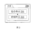
- the electronic device 200 for wireless communication includes a processing circuit 210 including a combining unit 211 and a control unit 213.
- the combining unit 211 is configured to combine user equipments employing short transmission intervals. Accordingly, the control unit 213 is configured to perform control such that the transport blocks of the combined user equipment are transmitted in the same subframe.
- the combining unit 211 may combine according to the similarity between user equipments.
- the similarity may be determined based on the priority of the information to be transmitted, the amount of data of the information to be transmitted, the location of the user equipment, and the moving speed of the user equipment.
- control unit 111 may be configured to perform control such that transmission blocks independent of each other are transmitted in the same subframe, if predetermined conditions are satisfied.
- the predetermined condition may include: the multiple user equipments sharing the same resource pool perform the short-range service communication at the first transmission time interval and the short transmission time interval, respectively. If the predetermined condition is met, it may happen that the user equipment adopting the TTI has a problem that the sensing measurement is inaccurate due to the user equipment of the sTTI, and thus the combined transmission of the transport block may be triggered to alleviate the problem.
- the predetermined condition may further include: the channel busy rate of the resource pool is higher than a predetermined level; and the number ratio of the user equipment adopting the first transmission time interval to the user equipment adopting the short transmission time interval is in a predetermined range.
- triggering conditions are described below as an example of a user equipment in a vehicle that does not support sTTI (such as a vehicle called R14) and a vehicle that supports sTTI (such as a vehicle called R15).
- a resource pool an event is triggered when the following two conditions are met simultaneously:
- Condition 1 CBR>Coordinate thr ;
- CBR represents a channel busy rate, which may represent a proportion of subchannels whose S-RSSI exceeds a certain threshold
- Coordinate thr represents a threshold of a channel busy rate
- N R14 and N R15 respectively represent the number of R14 and R15 vehicles in the resource pool.
- ratioTypemin and ratioTypemax represent the lower and upper limits of the quantity ratio, respectively.
- condition 1 is used as one of the prerequisites for the mechanism to be triggered.
- Condition 2 is used as another trigger condition.
- the two conditions need to be met at the same time to trigger the pairing mechanism.
- a correspondence relationship can be set between Coordinate thr and (ratioTypemin, ratioTypemax).
- multiple combinations of the thresholds Coordinate thr and (ratioTypemin, ratioTypemax) may be employed.
- the combination of thresholds may be, for example, pre-configured by the network side, and a control node, such as an eNodeB, may optimize the threshold.
- a predetermined condition related to the communication status of the user equipment adopting the first transmission time interval may be set, for example, the frequency of transmission failure of the user equipment adopting the first transmission time interval reaches a predetermined level; or the first transmission time is adopted.
- the proportion of the scheduled user equipment that receives the unassigned scheduling allocation signaling reaches a predetermined level.
- the trigger condition will be described below using the Mode 4 R14 vehicle as an example of a user equipment employing the first transmission time interval.
- Condition 3 The Mode 4 vehicle is triggered by frequent transmission failure due to deviation of the sensing result.
- the probability of its transmission failure is P CRSfail .
- the transmission fails frequently and continues for a period of time, it can report this situation.
- control nodes such as eNodeB and trigger events.
- the failure probability threshold and the trigger duration may be configured by the base station according to the current resource pool condition of the cell. If the base station is not configured, the pre-configuration information may be used.
- the reporting activity and parameters may be configured by the eNodeB through RRC signaling or pre-configured in the SIB.
- the eNodeB can continuously optimize and correct the parameters in the internal judgment mechanism of the eNodeB according to the CBR and N R14 /N R15 in the resource pool when the Mode 4 R14 vehicle reports the situation.
- the base station can be configured according to the current resource pool condition of the cell. If the base station is not configured, the pre-configuration information can be used. .
- the reporting activity and parameters may be configured by the eNodeB through RRC signaling or pre-configured in the SIB.
- the eNodeB will continuously optimize and correct the parameters in the eNodeB internal judgment mechanism according to the CBR and NR14/NR15 in the resource pool when the Mode 4 R14 vehicle reports the situation.
- the above trigger condition is for processing at a central control node such as a base station, but for example, when the vehicle (or other type of user equipment) is outside the network coverage, there is no central control node to control and notify the vehicle coexistence situation, in this case
- a central control node such as a base station
- Some examples of applications for the R15 V2X include, but are not limited to, vehicle queuing, cooperative driving, and Extended Sensor. In these instances, frequent sTTI transmissions are made between vehicles.
- the R15 vehicle can trigger a pairing mechanism and a subsequent compatible SA transmission scheme when it is found that there is an R14 vehicle around.
- the manager can notify the team members, and use the matching mechanism when assigning resources to the team members to make the members
- the sTTI transmission fills up the sub-frames used for transmission.
- the paired vehicle can be notified how to send the SA.
- the R15 vehicle can trigger the pairing mechanism itself when it finds that there is an R14 vehicle around it, without reporting it, or it can be triggered after the control node (similar to the base station and fleet manager).
- the foregoing embodiment relates to the transmission of scheduling allocation (SA) signaling and the case where the user equipment adopting the first transmission time interval receives the SA that cannot be decoded.
- SA scheduling allocation
- 3GPP expects that PC5 operations using sTTI can coexist in the same resource pool in the same or different SA format as the operations in R14.
- the SA transmits on the Physical Pass-Link Control Channel (PSCCH), which at least indicates the location and duration of the associated data.
- PSCCH Physical Pass-Link Control Channel
- the user equipment can sense the corresponding data to obtain its energy or physical pass-through link shared channel reference signal received power (PSSCH-RSRP).
- PSSCH-RSRP physical pass-through link shared channel reference signal received power
- the user equipment needs a sensing operation to determine a candidate resource set, one method is to decode the SA, and the other method is to measure the through link received signal strength indication of the subframe (S-RSSI ) value, ie energy sensing.
- S-RSSI subframe
- the R14 user equipment For the R15 user equipment, if the SA also uses sTTI for transmission, the R14 user equipment cannot decode it, and thus the PSSCH-RSRP measurement cannot be performed, thus affecting the sensing operation. In addition, even in the case where the R14 user equipment can decode the SA, the R14 user equipment can obtain the information in the R15 SA, but cannot use one time slot for transmission, resulting in fragmentation of time resources. The above issues can affect the resource (re)selection process of R14 user equipment and reduce system performance.
- an electronic device for wireless communication is further configured to determine a transmission mode and/or content of scheduling allocation signaling.
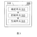
- the electronic device 300 includes a processing circuit 310 including a determining unit 311 and a control unit 313.
- the determining unit 311 is configured to determine a transmission mode and/or content of the scheduling allocation signaling for the subframe according to the transport block to be transmitted in the same subframe.
- control unit 313 can perform control to transmit scheduling allocation signaling as determined.
- the transmission mode of the scheduling allocation signaling may include: transmitting a scheduling allocation signaling having the same length as the first transmission time interval; transmitting a scheduling allocation signaling having the same length as the first transmission time interval, and n lengths respectively Scheduling allocation signaling corresponding to a short transmission time interval of a transport block in a subframe; or transmitting n scheduling allocation signalings having the same length as the first transmission time interval, where n is the number of transport blocks in the subframe.
- the scheduling assignment signaling may be implemented by an SCI format (Direct Link Control Information Format), and the determining unit 311 may be further configured to add information related to the transmission resource to the reserved bits of the SCI format.
- SCI format Direct Link Control Information Format
- the determining unit 311 may be configured to add information related to the transmission resource to the reserved bits of the scheduling allocation signaling; the control unit 313 may control to notify the user equipment of the definition of the added information in the system information block.
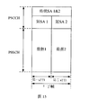
- the R15 vehicles transmitted in sTTI will be transmitted in one subframe after pairing, which will solve the problem of time fragmentation and inaccurate S-RSSI results. Furthermore, in order to solve the problem that the R14 vehicle cannot decode the short SA, the pairing user needs to transmit at least one SA of one subframe in the format of R14 SA, for example, SCI format 1. Understandably, we can also implement this by adding a new SCI format.
- the SA content of the two paired vehicles will be very similar. According to the analysis in Table 1, the only difference that may exist between the two will appear in the "frequency resource location of initial transmission and retransmission" field, and the calculation of this domain value is as follows:
- N subCH is the total number of subchannels in the resource pool determined by the higher layer parameter numSubchannel-r14.
- the two vehicles Since the message size is close to one of the screening criteria of the paired object, when this point is satisfied, the two vehicles will be assigned the same number of subchannels, then the value of the paired vehicle in the "frequency resource location of initial transmission and retransmission" field There can be no difference, or the difference is only the starting subchannel index number s difference. Therefore, the reserved bits in SCI format 1 can be used to represent the difference between the locations of the two paired user frequency resources. Name the new field in the reserved bit "RIV offset", that is, Its definition will be configured to the vehicle in the SIB.
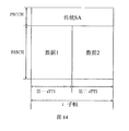
- Option 2 Transfer a redesigned legacy SA and two short SAs
- the mode 4 vehicle only needs the contents of the following three domains in SCI format 1: priority; frequency resource location of initial transmission and retransmission; resource reservation (mode 4 only).
- the paired vehicles need to each send an additional short SA, as shown in FIG.
- the short SA is the SA dedicated to the R15 vehicle and does not need to be decoded by the R14 vehicle.
- the short SA is the SA dedicated to the R15 vehicle and does not need to be decoded by the R14 vehicle.
- the format of the SA should be the same as SCI format 1 and sent in TTI.
- this SA is transmitted in TTI, in order for the R15 receiver to obtain the information required for decoding, its content is different from the conventional TTI, but the number of bits occupied by each domain does not change. At the same time, the content is the same as the content of the short SA, but the number of bits may be different. Moreover, since both SAs are transmitted in the same subframe and are transmitted in the TTI, in order to distinguish which time slot the SA indicates, it is necessary to add a "slot index" to the reserved bit, occupying 1 bit. In this solution, the SA is referred to as a long SA, and the details are as shown in Table 4. The italicized part of the table is the domain necessary for perceptual operations, and its number of bits and content should be compatible with R14.
- the base station selects the SA transmission scheme for the paired user and decides who to send, which will inform the paired user in the SL (Through Link) authorization.
- SA index in the SL authorization, occupying 2bits, and its meaning is shown in Table 5.
- the pairing user decides the way to send the SA according to the difference of the information between the two parties in the pairing interaction process.
- control circuit 310 can further include a generating unit 315 configured to generate indication information for indicating to the user equipment the manner in which the scheduling signaling is transmitted.
- indication information may be included in radio resource control signaling or non-access stratum signaling.
- the base station can, for example, use an indicator bit to inform the R15 vehicle that the indicator can be added in the system control signaling, including but It is not limited to signaling such as RRC or NAS.
- RRC signaling as an example to define an indication bit.
- the indicator bits can be defined as follows:
- the indicator bit is named "coordination index", which occupies 1 bit in the RRC signaling, and informs the R15 vehicle whether it can transmit the SA and data by itself in the sTTI in the current resource pool.
- the R15 vehicle can transmit SA and data by itself in sTTI; when the Coordination Index is set to "1", it will be in resource (re)selection/allocation and SA transmission.
- the mechanism as in the above embodiment is employed.
- the value of "coordination index” may always be “0" in the R15 dedicated resource pool, only when the R15 vehicle enters the shared resource pool.
- the value of the indicator bit changes after the event is triggered.
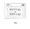
- the electronic device 400 includes a processing circuit 410 including a determining unit 411 and a control unit 413.
- the determining unit 411 is configured to determine scheduling allocation signaling, where the scheduling signal is configured to include at least one length and the first transmission time, in the case that the user equipment performs the short-range traffic communication at a short transmission time interval smaller than the first transmission time interval. Scheduling allocation signaling with the same interval.
- the control unit 413 is configured to control the sidelink grant such that at least two transport blocks each having a short transmission time interval are transmitted in the same subframe, wherein the length of the subframe is the same as the first transmission time interval.
- the monitoring of the trigger condition is performed on the base station side.
- the user equipment side can report to the base station based on the predetermined condition.
- the base station can notify the user equipment to adopt a corresponding coordination mechanism by, for example, “coordinating index”.
- Mode 3 R15 user equipment For the Mode 3 R15 user equipment, it requests the sidelink resource from the base station, and the base station determines the pairing mode and the like, and performs sidelink authorization.
- Mode 4 R15 user equipment For Mode 4 R15 user equipment, it can be paired by itself.
- the pairing mechanism for the Mode 3 vehicle is described.
- the base station will perform a pairing mechanism.
- the mode 3 vehicle when applying for a resource, can upload the recipient ID in the "SidelinkUEInformation” field of the RRC, upload the priority in the "UEAssistanceInformation” field (PPPP), upload the detailed geographical location information in the IE LocationInfo, and the BSR in the BSR.
- the size of the resources required for its transfer is described in the Control Unit.
- the base station will pair the vehicles that apply for the resources according to the information uploaded by the vehicle.
- the basic matching principle is to make the vehicles with similar similarity become the paired vehicles as much as possible, if the number of consecutive sTTIs required for the transmission of R15 VUE For even numbers, no pairing is required.
- the base station allocates resources for the paired vehicle in a subframe size, and indicates in which time slot the two are respectively transmitted.
- the R14 vehicle Since the purpose of the paired transmission is to have two independent sTTIs transmitted in one subframe, the R14 vehicle appears to be the same as one TTI transmission in one R14 subframe. Therefore, the principle of pairing is to make the matching power of the paired users as close as possible, occupying a similar position and size of resources.
- priority is the most important factor in the pairing criteria because it is fixed (determined by the vehicle's V2X service type) and determines the size of the transmit power, and when the sidelink transmission conflicts with the upstream transmission.
- two users transmitting in the same subframe must first ensure that the service priorities are the same; secondly, the geographical locations are similar, because the time for requesting the two is similar, and in the same resource pool, the determining factors of the MCS are mainly It is the channel quality and the bit error rate.
- the base station can select the same MCS for users with similar geographical locations.
- the message size is similar.
- the base station can be Two paired users are assigned the same number of subchannels.
- the three criteria for selecting a paired vehicle have a priority from high to low: business priority, geographic location, and message size.
- the pairing mechanism needs to compare the vehicle information that is simultaneously transmitted, the resources are allocated, so that the sidelink transmission fills up as many sub-frames as possible, and the transmission information of the paired users is not much different. Therefore, the centrally controlled scheduling mode of mode 3 is more suitable for the pairing mechanism, however the pairing mechanism can also be used for the mode 4 user equipment.
- the vehicle broadcasts a pairing request to the surrounding vehicle, and the pairable R15 mode 4 vehicle will reply to the request;
- the pairable vehicles within the communication range multicast their transmission information in the pairable vehicle group, including priority, geographic location, communication destination, message size, and resource reservation information.
- the vehicle will select the appropriate vehicle for pairing in a similar manner as in the previous embodiment.
- the paired vehicle can combine the perceived results of both, and can select transmission resources and SA transmission schemes.
- FIG. 1 An example process for pairing Mode 4 vehicles is shown in FIG. 1
- the present invention also includes a corresponding wireless communication device, which may include a transceiver device and an electronic device according to the foregoing embodiments.
- the wireless communication method in the wireless communication method according to the present embodiment, in the case where the user equipment performs the close-range service communication at a short transmission time interval smaller than the first transmission time interval (Y in S510), so that the same At least two mutually independent transport blocks each having a short transmission time interval are transmitted in the subframe (S520), wherein the length of the subframe is the same as the first transmission time interval.
- the foregoing embodiment relates to a pairing mechanism for a vehicle that schedules and autonomously selects resources for a base station.
- the eNodeB centrally schedules resources for multiple independent sTTI transmissions; for the latter, the vehicle will interact with surrounding vehicles, and the paired vehicles may be in range Multicast your own transmission information and select the appropriate vehicle for pairing transmission.
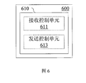
- an electronic device 600 for a user equipment side includes a processing circuit 610.
- the processing circuit 610 includes a reception control unit 611 and a transmission control unit 613.
- This embodiment corresponds to a user equipment (eg, Mode 3 R15 VUE) employing a short transmission time interval.
- a user equipment eg, Mode 3 R15 VUE
- the reception control unit 611 is configured to perform control to receive indication information from the control node.
- the control node may for example comprise a base station, an RSU or another user equipment.
- the transmission control unit 613 is configured to perform control based on the indication information such that the transmission block of the user equipment has another short transmission time in the case where the user equipment performs the short-range communication communication at a short transmission time interval smaller than the first transmission time interval.
- the spaced transport blocks are transmitted in the same subframe, wherein the length of the subframe is the same as the first transmission time interval.
- Additional transport blocks with short transmission time intervals may comprise transport blocks of the user equipment or transport blocks of its user equipment.
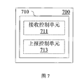
- an electronic device 700 for a user equipment side includes a processing circuit 710.
- Processing circuit 710 includes a receive control unit 711.
- the processing circuit 710 may further include a report control unit 713.
- This embodiment corresponds to a user equipment (eg, Mode 3 R14 VUE) that uses a long transmission time interval.
- a user equipment eg, Mode 3 R14 VUE
- the receiving control unit 711 is configured to, when the user equipment performs the short-range traffic communication at the first transmission time interval, to control to receive the short transmission time that is different from the first transmission time interval, respectively, transmitted in the same subframe Scheduling allocation signaling associated with at least two mutually independent transport blocks, wherein the length of the subframe is the same as the first transmission time interval.
- the receiving control unit 711 can also be configured to perform control to make a perceptual measurement of the transport block.
- the reporting control unit 713 is configured to report the corresponding indication information to the control node in the following cases: the frequency of the transmission failure of the user equipment reaches a predetermined level; or the proportion of the scheduling allocation signaling that the user equipment receives the undecodeable reaches a predetermined level.
- the embodiment of the present application further includes a wireless communication device and a wireless communication method corresponding to the above-mentioned electronic devices 600, 700 for the user equipment side.
- the embodiment of the present application further includes an electronic device for wireless communication, including a control unit configured to perform short-range service communication at a short transmission time interval smaller than a first transmission time interval by the user equipment, Control is performed such that at least two mutually independent transport blocks each having a short transmission time interval are transmitted in the same subframe, wherein the length of the subframe is the same as the first transmission time interval.
- a control unit configured to perform short-range service communication at a short transmission time interval smaller than a first transmission time interval by the user equipment, Control is performed such that at least two mutually independent transport blocks each having a short transmission time interval are transmitted in the same subframe, wherein the length of the subframe is the same as the first transmission time interval.
- the embodiment of the present application further includes an electronic device for wireless communication, comprising: a determining unit configured to determine, when the user equipment performs short-range service communication at a short transmission time interval less than the first transmission time interval Scheduling allocation signaling, the scheduling allocation signaling includes at least one scheduling allocation signaling having the same length as the first transmission time interval; and a control unit configured to perform control such that transmissions in the same subframe each have a short transmission time interval At least two transport blocks, wherein the length of the subframe is the same as the first transmission time interval.
- the embodiment of the present application further includes an electronic device for the user equipment side, including: a receiving control unit configured to perform control to receive indication information from the control node; and a transmission control unit configured to be at the user equipment
- the control is performed based on the indication information such that the transport block of the user equipment is transmitted in the same subframe as another transport block having a short transmission time interval,
- the length of the subframe is the same as the first transmission time interval.
- the embodiment of the present application further includes an electronic device for the user equipment side, including: a control unit configured to perform control to receive and perform the short-range service communication at the first transmission time interval of the user equipment.
- Scheduling allocation signaling associated with at least two mutually independent transport blocks each having a shorter transmission time interval than the first transmission time interval transmitted in the same subframe, wherein the length of the subframe is the same as the first transmission time interval.
- the various steps of the above methods, as well as the various constituent modules and/or units of the above-described apparatus may be implemented as software, firmware, hardware or a combination thereof.
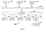
- a program constituting software for implementing the above method may be installed from a storage medium or a network to a computer having a dedicated hardware structure (for example, the general-purpose computer 2000 shown in FIG. 17), which is installed.
- a dedicated hardware structure for example, the general-purpose computer 2000 shown in FIG. 17
- an arithmetic processing unit (i.e., CPU) 2001 executes various processes in accordance with a program stored in a read only memory (ROM) 2002 or a program loaded from a storage portion 2008 to a random access memory (RAM) 2003.
- ROM read only memory
- RAM random access memory
- data required when the CPU 2001 executes various processes and the like is also stored as needed.
- the CPU 2001, the ROM 2002, and the RAM 2003 are linked to each other via the bus 2004.
- the input/output interface 2005 is also linked to the bus 2004.
- the following components are linked to the input/output interface 2005: an input portion 2006 (including a keyboard, a mouse, etc.), an output portion 2007 (including a display such as a cathode ray tube (CRT), a liquid crystal display (LCD), etc., and a speaker, etc.) , storage part 2008 (including hard disk, etc.), communication part 2009 (including network interface cards such as LAN cards, modems, etc.).
- the communication section 2009 performs communication processing via a network such as the Internet.
- Driver 2010 can also be linked to input/output interface 2005 as needed.
- a removable medium 2011 such as a magnetic disk, an optical disk, a magneto-optical disk, a semiconductor memory or the like is mounted on the drive 2010 as needed, so that the computer program read therefrom is installed into the storage portion 2008 as needed.
- a program constituting the software is installed from a network such as the Internet or a storage medium such as the detachable medium 2011.
- such a storage medium is not limited to the detachable medium 2011 shown in FIG. 17 in which a program is stored and distributed separately from the device to provide a program to the user.
- Examples of the detachable medium 2011 include a magnetic disk (including a floppy disk (registered trademark)), an optical disk (including a compact disk read only memory (CD-ROM) and a digital versatile disk (DVD)), and a magneto-optical disk (including a mini disk (MD) (registered trademark) )) and semiconductor memory.
- the storage medium may be a ROM 2002, a hard disk included in the storage section 2008, or the like, in which programs are stored, and distributed to the user together with the device containing them.
- Embodiments of the present invention also relate to a program product for storing a machine readable instruction code.
- the instruction code is read and executed by a machine, the above-described method according to an embodiment of the present invention can be performed.
- a storage medium for carrying a program product storing the above-described storage machine readable instruction code is also included in the disclosure of the present invention.
- the storage medium includes, but is not limited to, a floppy disk, an optical disk, a magneto-optical disk, a memory card, a memory stick, and the like.
- Embodiments of the present application also relate to the following electronic devices.
- the electronic device can be implemented as any type of base station, such as a gNB or an evolved Node B (eNB), such as a macro eNB and a small eNB.
- the small eNB may be an eNB covering a cell smaller than the macro cell, such as a pico eNB, a micro eNB, and a home (femto) eNB.
- the electronic device can be implemented as any other type of base station, such as a NodeB and a base transceiver station (BTS).
- BTS base transceiver station
- the electronic device can include: a body (also referred to as a base station device) configured to control wireless communication; and one or more remote wireless headends (RRHs) disposed at a different location than the body.
- a body also referred to as a base station device
- RRHs remote wireless headends
- various types of terminals which will be described below, can operate as a base station by performing base station functions temporarily or semi-persistently.
- the electronic device can be implemented as a mobile terminal (such as a smart phone, a tablet personal computer (PC), a notebook PC, a portable game terminal, a portable/encrypted dog type mobile router, and a digital camera device) or Vehicle terminal (such as car navigation equipment).
- the electronic device may be a wireless communication module (such as an integrated circuit module including a single or a plurality of wafers) mounted on each of the above terminals.
- FIG. 18 is a block diagram showing an example of a schematic configuration of a smartphone 2500 to which the technology of the present disclosure can be applied.
- the smart phone 2500 includes a processor 2501, a memory 2502, a storage device 2503, an external connection interface 2504, an imaging device 2506, a sensor 2507, a microphone 2508, an input device 2509, a display device 2510, a speaker 2511, a wireless communication interface 2512, and one or more An antenna switch 2515, one or more antennas 2516, a bus 2517, a battery 2518, and an auxiliary controller 2519.
- the processor 2501 may be, for example, a CPU or a system on chip (SoC), and controls the functions of the application layer and the other layers of the smartphone 2500.
- the memory 2502 includes a RAM and a ROM, and stores data and programs executed by the processor 2501.
- the storage device 2503 may include a storage medium such as a semiconductor memory and a hard disk.
- the external connection interface 2504 is an interface for connecting an external device such as a memory card and a universal serial bus (USB) device to the smartphone 2500.
- USB universal serial bus
- the image pickup device 2506 includes an image sensor such as a charge coupled device (CCD) and a complementary metal oxide semiconductor (CMOS), and generates a captured image.
- Sensor 2507 can include a set of sensors, such as a measurement sensor, a gyro sensor, a geomagnetic sensor, and an acceleration sensor.
- the microphone 2508 converts the sound input to the smartphone 2500 into an audio signal.
- the input device 2509 includes, for example, a touch sensor, a keypad, a keyboard, a button, or a switch configured to detect a touch on the screen of the display device 2510, and receives an operation or information input from a user.
- the display device 2510 includes screens such as a liquid crystal display (LCD) and an organic light emitting diode (OLED) display, and displays an output image of the smartphone 2500.
- the speaker 2511 converts the audio signal output from the smartphone 2500 into a sound.
- the wireless communication interface 2512 supports any cellular communication scheme (such as LTE and LTE-Advanced) and performs wireless communication.
- Wireless communication interface 2512 may generally include, for example, a baseband (BB) processor 2513 and radio frequency (RF) circuitry 2514.
- the BB processor 2513 can perform, for example, encoding/decoding, modulation/demodulation, and multiplexing/demultiplexing, and performs various types of signal processing for wireless communication.
- the RF circuit 2514 may include, for example, a mixer, a filter, and an amplifier, and transmits and receives a wireless signal via the antenna 2516.
- the wireless communication interface 2512 can be a chip module on which the BB processor 2513 and the RF circuit 2514 are integrated. As shown in FIG.
- the wireless communication interface 2512 can include a plurality of BB processors 2513 and a plurality of RF circuits 2514.
- FIG. 18 illustrates an example in which the wireless communication interface 2512 includes a plurality of BB processors 2513 and a plurality of RF circuits 2514, the wireless communication interface 2512 may also include a single BB processor 2513 or a single RF circuit 2514.
- wireless communication interface 2512 can support additional types of wireless communication schemes, such as short-range wireless communication schemes, near field communication schemes, and wireless local area network (LAN) schemes.
- the wireless communication interface 2512 can include a BB processor 2513 and RF circuitry 2514 for each wireless communication scheme.
- Each of the antenna switches 2515 switches the connection destination of the antenna 2516 between a plurality of circuits included in the wireless communication interface 2512, such as circuits for different wireless communication schemes.
- Each of the antennas 2516 includes a single or multiple antenna elements (such as multiple antenna elements included in a MIMO antenna) and is used by the wireless communication interface 2512 to transmit and receive wireless signals.
- the smartphone 2500 can include a plurality of antennas 2516.
- FIG. 18 shows an example in which the smartphone 2500 includes a plurality of antennas 2516, the smartphone 2500 may also include a single antenna 2516.
- smart phone 2500 can include an antenna 2516 for each wireless communication scheme.
- the antenna switch 2515 can be omitted from the configuration of the smartphone 2500.
- the bus 2517 has a processor 2501, a memory 2502, a storage device 2503, an external connection interface 2504, an imaging device 2506, a sensor 2507, a microphone 2508, an input device 2509, a display device 2510, a speaker 2511, a wireless communication interface 2512, and an auxiliary controller 2519. connection.
- Battery 2518 provides power to various blocks of smart phone 2500 shown in FIG. 18 via a feeder, which is partially shown as a dashed line in the figure.
- the secondary controller 2519 operates the minimum required function of the smartphone 2500, for example, in a sleep mode.
- the transceiver or transceiver unit of the wireless communication device may be implemented by the wireless communication interface 2512.
- At least a portion of the processing circuitry of the electronic device or information processing device for wireless communication and/or the functions of the various units in accordance with embodiments of the present invention may also be implemented by the processor 2501 or the auxiliary controller 2519.
- the power consumption of the battery 2518 can be reduced by performing a portion of the functions of the processor 2501 by the auxiliary controller 2519.
- the processor 2501 or the auxiliary controller 2519 may perform at least a part of the functions of the processing circuit and/or each unit of the electronic device or the wireless communication device according to an embodiment of the present invention by executing a program stored in the memory 2502 or the storage device 2503. .
- the eNB 2300 includes one or more antennas 2310 and base station devices 2320.
- the base station device 2320 and each antenna 2310 may be connected to each other via a radio frequency (RF) cable.
- RF radio frequency
- Each of the antennas 2310 includes a single or multiple antenna elements, such as multiple antenna elements included in a multiple input multiple output (MIMO) antenna, and is used by the base station device 2320 to transmit and receive wireless signals.
- the eNB 2300 may include a plurality of antennas 2310.
- multiple antennas 2310 can be compatible with multiple frequency bands used by eNB 2300.
- FIG. 19 illustrates an example in which the eNB 2300 includes a plurality of antennas 2310, the eNB 2300 may also include a single antenna 2310.
- the base station device 2320 includes a controller 2321, a memory 2322, a network interface 2323, and a wireless communication interface 2325.
- the controller 2321 can be, for example, a CPU or a DSP, and operates various functions of higher layers of the base station device 2320. For example, controller 2321 generates data packets based on data in signals processed by wireless communication interface 2325 and delivers the generated packets via network interface 2323. The controller 2321 can bundle data from a plurality of baseband processors to generate bundled packets and deliver the generated bundled packets. The controller 2321 may have a logical function that performs control such as radio resource control, radio bearer control, mobility management, admission control, and scheduling. This control can be performed in conjunction with nearby eNBs or core network nodes.
- the memory 2322 includes a RAM and a ROM, and stores programs executed by the controller 2321 and various types of control data such as a terminal list, transmission power data, and scheduling data.
- the network interface 2323 is a communication interface for connecting the base station device 2320 to the core network 2324. Controller 2321 can communicate with a core network node or another eNB via network interface 2323. In this case, the eNB 2300 and the core network node or other eNBs may be connected to each other through a logical interface such as an S1 interface and an X2 interface.
- the network interface 2323 can also be a wired communication interface or a wireless communication interface for wireless backhaul lines. If the network interface 2323 is a wireless communication interface, the network interface 2323 can use a higher frequency band for wireless communication than the frequency band used by the wireless communication interface 2325.
- the wireless communication interface 2325 supports any cellular communication schemes, such as Long Term Evolution (LTE) and LTE-Advanced, and provides wireless connectivity to terminals located in cells of the eNB 2300 via the antenna 2310.
- Wireless communication interface 2325 can typically include, for example, BB processor 2326 and RF circuitry 2327.
- the BB processor 2326 can perform, for example, encoding/decoding, modulation/demodulation, and multiplexing/demultiplexing, and performs layers (eg, L1, Medium Access Control (MAC), Radio Link Control (RLC), and Packet Data Convergence Protocol (PDCP)) Various types of signal processing.
- BB processor 2326 may have some or all of the above described logic functions.
- the BB processor 2326 can be a memory that stores a communication control program, or a module that includes a processor and associated circuitry configured to execute the program.
- the update program can cause the functionality of the BB processor 2326 to change.
- the module can be a card or blade that is inserted into the slot of the base station device 2320. Alternatively, the module can also be a chip mounted on a card or blade.
- the RF circuit 2327 may include, for example, a mixer, a filter, and an amplifier, and transmits and receives a wireless signal via the antenna 2310.
- the wireless communication interface 2325 can include a plurality of BB processors 2326.
- multiple BB processors 2326 can be compatible with multiple frequency bands used by eNB 2300.
- the wireless communication interface 2325 can include a plurality of RF circuits 2327.
- multiple RF circuits 2327 can be compatible with multiple antenna elements.
- FIG. 19 illustrates an example in which the wireless communication interface 2325 includes a plurality of BB processors 2326 and a plurality of RF circuits 2327, the wireless communication interface 2325 may also include a single BB processor 2326 or a single RF circuit 2327.
- the transceiver or transceiver unit of the wireless communication device may be implemented by the wireless communication interface 2325.
- the controller 2321 can perform at least a portion of the functions of the processing circuitry and/or the various units of the electronic device or wireless communication device in accordance with an embodiment of the present invention by executing a program stored in the memory 2322.
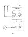
- FIG. 20 is a block diagram showing an example of a schematic configuration of a car navigation device 2120 to which the technology of the present disclosure can be applied.
- the car navigation device 2120 includes a processor 2121, a memory 2122, a global positioning system (GPS) module 2124, a sensor 2125, a data interface 2126, a content player 2127, a storage medium interface 2128, an input device 2129, a display device 2130, a speaker 2131, and a wireless device.
- the processor 2121 can be, for example, a CPU or SoC and controls the navigation function and additional functions of the car navigation device 2120.
- the memory 2122 includes a RAM and a ROM, and stores data and programs executed by the processor 2121.
- the GPS module 2124 uses the GPS signals received from the GPS satellites to measure the position (such as latitude, longitude, and altitude) of the car navigation device 2120.
- Sensor 2125 can include a set of sensors, such as a gyro sensor, a geomagnetic sensor, and an air pressure sensor.
- the data interface 2126 is connected to, for example, the in-vehicle network 2141 via a terminal not shown, and acquires data (such as vehicle speed data) generated by the vehicle.
- the content player 2127 reproduces content stored in a storage medium such as a CD and a DVD, which is inserted into the storage medium interface 2128.
- the input device 2129 includes, for example, a touch sensor, a button or a switch configured to detect a touch on the screen of the display device 2130, and receives an operation or information input from a user.
- the display device 2130 includes a screen such as an LCD or an OLED display, and displays an image of the navigation function or reproduced content.
- the speaker 2131 outputs the sound of the navigation function or the reproduced content.
- the wireless communication interface 2133 supports any cellular communication scheme (such as LTE and LTE-Advanced) and performs wireless communication.
- Wireless communication interface 2133 may typically include, for example, BB processor 2134 and RF circuitry 2135.
- the BB processor 2134 can perform, for example, encoding/decoding, modulation/demodulation, and multiplexing/demultiplexing, and performs various types of signal processing for wireless communication.
- the RF circuit 2135 may include, for example, a mixer, a filter, and an amplifier, and transmits and receives a wireless signal via the antenna 2137.
- the wireless communication interface 2133 can also be a chip module on which the BB processor 2134 and the RF circuit 2135 are integrated. As shown in FIG.
- the wireless communication interface 2133 may include a plurality of BB processors 2134 and a plurality of RF circuits 2135.
- FIG. 20 illustrates an example in which the wireless communication interface 2133 includes a plurality of BB processors 2134 and a plurality of RF circuits 2135, the wireless communication interface 2133 may also include a single BB processor 2134 or a single RF circuit 2135.
- the wireless communication interface 2133 can support additional types of wireless communication schemes, such as short-range wireless communication schemes, near field communication schemes, and wireless LAN schemes.
- the wireless communication interface 2133 may include a BB processor 2134 and an RF circuit 2135 for each wireless communication scheme.
- Each of the antenna switches 2136 switches the connection destination of the antenna 2137 between a plurality of circuits included in the wireless communication interface 2133, such as circuits for different wireless communication schemes.
- Each of the antennas 2137 includes a single or multiple antenna elements (such as multiple antenna elements included in a MIMO antenna) and is used by the wireless communication interface 2133 to transmit and receive wireless signals.
- the car navigation device 2120 can include a plurality of antennas 2137.
- FIG. 20 shows an example in which the car navigation device 2120 includes a plurality of antennas 2137, the car navigation device 2120 may also include a single antenna 2137.
- car navigation device 2120 can include an antenna 2137 for each wireless communication scheme.
- the antenna switch 2136 can be omitted from the configuration of the car navigation device 2120.
- Battery 2138 provides power to various blocks of car navigation device 2120 shown in FIG. 20 via feeders, which are partially shown as dashed lines in the figures. Battery 2138 accumulates power supplied from the vehicle.
- the transceiver or transceiver unit of the wireless communication device may be implemented by the wireless communication interface 2133.
- Processing circuitry of the electronic device or wireless communication device and/or at least a portion of the functionality of the various units in accordance with embodiments of the present invention may also be implemented by processor 2121.
- the technology of the present disclosure may also be implemented as an onboard system (or vehicle) 2140 that includes one or more of the car navigation device 2120, the in-vehicle network 2141, and the vehicle module 2142.
- vehicle module 2142 generates vehicle data such as vehicle speed, engine speed, and fault information, and outputs the generated data to the in-vehicle network 2141.
- the method of the present invention is not limited to being performed in the chronological order described in the specification, and may be performed in other chronological order, in parallel, or independently. Therefore, the order of execution of the methods described in the present specification does not limit the technical scope of the present invention.
Landscapes
- Engineering & Computer Science (AREA)
- Signal Processing (AREA)
- Computer Networks & Wireless Communication (AREA)
- Quality & Reliability (AREA)
- Physics & Mathematics (AREA)
- Electromagnetism (AREA)
- Health & Medical Sciences (AREA)
- Computing Systems (AREA)
- General Health & Medical Sciences (AREA)
- Medical Informatics (AREA)
- Mobile Radio Communication Systems (AREA)
Abstract
Priority Applications (7)
| Application Number | Priority Date | Filing Date | Title |
|---|---|---|---|
| JP2019571405A JP7131573B2 (ja) | 2017-07-10 | 2018-07-04 | 電子装置及び無線通信方法 |
| US16/605,807 US11096192B2 (en) | 2017-07-10 | 2018-07-04 | Electronic device and wireless communication method for proximity based communications via a sidelink |
| CN201880019115.1A CN110447199B (zh) | 2017-07-10 | 2018-07-04 | 电子装置和无线通信方法 |
| KR1020197036441A KR102508265B1 (ko) | 2017-07-10 | 2018-07-04 | 전자 디바이스 및 무선 통신 방법 |
| EP18832385.1A EP3654564B1 (fr) | 2017-07-10 | 2018-07-04 | Dispositif électronique, et procédé de communication sans fil |
| AU2018300489A AU2018300489A1 (en) | 2017-07-10 | 2018-07-04 | Electronic device and wireless communication method |
| RU2020105880A RU2020105880A (ru) | 2017-07-10 | 2018-07-04 | Электронное устройство и способ беспроводной связи |
Applications Claiming Priority (2)
| Application Number | Priority Date | Filing Date | Title |
|---|---|---|---|
| CN201710556453.6A CN109246582A (zh) | 2017-07-10 | 2017-07-10 | 电子装置和无线通信方法 |
| CN201710556453.6 | 2017-07-10 |
Publications (1)
| Publication Number | Publication Date |
|---|---|
| WO2019011168A1 true WO2019011168A1 (fr) | 2019-01-17 |
Family
ID=65002318
Family Applications (1)
| Application Number | Title | Priority Date | Filing Date |
|---|---|---|---|
| PCT/CN2018/094454 WO2019011168A1 (fr) | 2017-07-10 | 2018-07-04 | Dispositif électronique, et procédé de communication sans fil |
Country Status (8)
| Country | Link |
|---|---|
| US (1) | US11096192B2 (fr) |
| EP (1) | EP3654564B1 (fr) |
| JP (1) | JP7131573B2 (fr) |
| KR (1) | KR102508265B1 (fr) |
| CN (2) | CN109246582A (fr) |
| AU (1) | AU2018300489A1 (fr) |
| RU (1) | RU2020105880A (fr) |
| WO (1) | WO2019011168A1 (fr) |
Families Citing this family (4)
| Publication number | Priority date | Publication date | Assignee | Title |
|---|---|---|---|---|
| WO2019090522A1 (fr) * | 2017-11-08 | 2019-05-16 | Oppo广东移动通信有限公司 | Procédé d'attribution de ressources dans une communication d2d, dispositif terminal et dispositif de réseau |
| US11419128B2 (en) * | 2018-08-01 | 2022-08-16 | Panasonic Intellectual Property Corporation Of America | User equipment and communication methods |
| US10834704B2 (en) * | 2019-03-22 | 2020-11-10 | Asustek Computer Inc. | Method and apparatus for resource selection in sidelink transmission in a wireless communication system |
| CN112584447A (zh) * | 2019-09-29 | 2021-03-30 | 索尼公司 | 无线通信系统中的电子设备和方法 |
Citations (4)
| Publication number | Priority date | Publication date | Assignee | Title |
|---|---|---|---|---|
| CN105827385A (zh) * | 2016-06-01 | 2016-08-03 | 珠海市魅族科技有限公司 | 时延控制方法和时延控制系统 |
| US20170099127A1 (en) * | 2015-10-06 | 2017-04-06 | Lg Electronics Inc. | Method and device for performing channel estimation in wireless communication system |
| CN106788928A (zh) * | 2016-08-09 | 2017-05-31 | 北京展讯高科通信技术有限公司 | 导频符号位置确定方法、用户终端及基站 |
| CN106788926A (zh) * | 2015-11-25 | 2017-05-31 | 上海朗帛通信技术有限公司 | 一种降低网络延迟的无线通信方法和装置 |
Family Cites Families (9)
| Publication number | Priority date | Publication date | Assignee | Title |
|---|---|---|---|---|
| WO2014000205A1 (fr) * | 2012-06-28 | 2014-01-03 | 华为技术有限公司 | Procédé d'ajustement de configuration de ressources, contrôleur de réseau de radiocommunication, et station de base |
| WO2015053584A1 (fr) * | 2013-10-10 | 2015-04-16 | 엘지전자 주식회사 | Procédé de gestion de ressources de transmission en liaison montante dans un système de communications sans fil, et appareil correspondant |
| WO2016163623A1 (fr) * | 2015-04-08 | 2016-10-13 | 엘지전자(주) | Procédé d'émission et de réception de données dans un système de communication sans fil et appareil associé |
| CN107925551B (zh) * | 2015-09-02 | 2021-04-06 | 株式会社Ntt都科摩 | 用户终端、无线基站及无线通信方法 |
| JP6954841B2 (ja) * | 2015-12-25 | 2021-10-27 | 株式会社Nttドコモ | ユーザ端末及び無線基地局 |
| KR102202612B1 (ko) * | 2016-05-13 | 2021-01-13 | 텔레호낙티에볼라게트 엘엠 에릭슨(피유비엘) | 다운링크 송신들의 구성 |
| KR102364200B1 (ko) * | 2016-08-11 | 2022-02-17 | 삼성전자 주식회사 | 무선 통신 시스템에서 하향링크 제어 정보를 송수신하기 위한 방법 및 장치 |
| US11457419B2 (en) * | 2017-01-12 | 2022-09-27 | Ntt Docomo, Inc. | User terminal and radio communication method |
| CN115460697A (zh) * | 2017-03-23 | 2022-12-09 | 苹果公司 | 用于传输侧链路传输的方法、用户设备和存储介质 |
-
2017
- 2017-07-10 CN CN201710556453.6A patent/CN109246582A/zh active Pending
-
2018
- 2018-07-04 WO PCT/CN2018/094454 patent/WO2019011168A1/fr unknown
- 2018-07-04 US US16/605,807 patent/US11096192B2/en active Active
- 2018-07-04 JP JP2019571405A patent/JP7131573B2/ja active Active
- 2018-07-04 RU RU2020105880A patent/RU2020105880A/ru not_active Application Discontinuation
- 2018-07-04 KR KR1020197036441A patent/KR102508265B1/ko active IP Right Grant
- 2018-07-04 EP EP18832385.1A patent/EP3654564B1/fr active Active
- 2018-07-04 CN CN201880019115.1A patent/CN110447199B/zh active Active
- 2018-07-04 AU AU2018300489A patent/AU2018300489A1/en not_active Abandoned
Patent Citations (4)
| Publication number | Priority date | Publication date | Assignee | Title |
|---|---|---|---|---|
| US20170099127A1 (en) * | 2015-10-06 | 2017-04-06 | Lg Electronics Inc. | Method and device for performing channel estimation in wireless communication system |
| CN106788926A (zh) * | 2015-11-25 | 2017-05-31 | 上海朗帛通信技术有限公司 | 一种降低网络延迟的无线通信方法和装置 |
| CN105827385A (zh) * | 2016-06-01 | 2016-08-03 | 珠海市魅族科技有限公司 | 时延控制方法和时延控制系统 |
| CN106788928A (zh) * | 2016-08-09 | 2017-05-31 | 北京展讯高科通信技术有限公司 | 导频符号位置确定方法、用户终端及基站 |
Non-Patent Citations (1)
| Title |
|---|
| See also references of EP3654564A4 * |
Also Published As
| Publication number | Publication date |
|---|---|
| CN109246582A (zh) | 2019-01-18 |
| EP3654564A1 (fr) | 2020-05-20 |
| US20200128562A1 (en) | 2020-04-23 |
| JP2020527876A (ja) | 2020-09-10 |
| AU2018300489A1 (en) | 2020-02-27 |
| KR20200026190A (ko) | 2020-03-10 |
| RU2020105880A (ru) | 2021-08-10 |
| US11096192B2 (en) | 2021-08-17 |
| EP3654564B1 (fr) | 2022-09-14 |
| JP7131573B2 (ja) | 2022-09-06 |
| RU2020105880A3 (fr) | 2021-11-01 |
| EP3654564A4 (fr) | 2020-06-24 |
| KR102508265B1 (ko) | 2023-03-09 |
| CN110447199B (zh) | 2023-04-04 |
| CN110447199A (zh) | 2019-11-12 |
Similar Documents
| Publication | Publication Date | Title |
|---|---|---|
| CN110351858B (zh) | 网络调度ue传输与自主调度ue传输之间的资源池共享 | |
| US10531281B2 (en) | Apparatus and method in wireless communication system | |
| US20220385430A1 (en) | Apparatus and method in wireless communication system, and computer-readable storage medium | |
| WO2017005164A1 (fr) | Dispositif de communication sans fil et procédé de communication sans fil | |
| WO2016165646A1 (fr) | Dispositif électronique et procédé utilisés pour des communications sans fil | |
| CN111654842B (zh) | 终端设备、通信控制方法和通信控制设备 | |
| US20210282188A1 (en) | Electronic device for wireless communication system, method and storage medium | |
| WO2017076178A1 (fr) | Appareils et procédés sur le côté station de base et le côté équipement d'utilisateur, et système de communications sans fil | |
| EP3439403A1 (fr) | Dispositif et procédé | |
| US11470584B2 (en) | Communication device | |
| CN112514519B (zh) | 通信设备 | |
| WO2019154387A1 (fr) | Dispositif électronique, procédé de radiocommunication et support d'enregistrement lisible par ordinateur | |
| CN110447199B (zh) | 电子装置和无线通信方法 | |
| WO2019154389A1 (fr) | Dispositif électronique, procédé de communication radio et support d'informations lisible par ordinateur | |
| WO2020259363A1 (fr) | Dispositif électronique et procédé de communication sans fil, et support de stockage lisible par ordinateur | |
| CN116326139A (zh) | 用于无线通信的电子设备、方法和存储介质 | |
| JP2023536200A (ja) | ロング物理サイドリンクフィードバックチャネル(psfch)フォーマットによるpsfchレンジ拡張 | |
| JP2023546906A (ja) | サイドリンクスケジューリングのオフロードによるユーザ機器の省電力化 | |
| US11997716B2 (en) | Electronic device for wireless communication system, method and storage medium | |
| WO2021204108A1 (fr) | Dispositif électronique, procédé de communication et support de stockage |
Legal Events
| Date | Code | Title | Description |
|---|---|---|---|
| 121 | Ep: the epo has been informed by wipo that ep was designated in this application |
Ref document number: 18832385 Country of ref document: EP Kind code of ref document: A1 |
|
| ENP | Entry into the national phase |
Ref document number: 20197036441 Country of ref document: KR Kind code of ref document: A |
|
| ENP | Entry into the national phase |
Ref document number: 2019571405 Country of ref document: JP Kind code of ref document: A |
|
| NENP | Non-entry into the national phase |
Ref country code: DE |
|
| ENP | Entry into the national phase |
Ref document number: 2018832385 Country of ref document: EP Effective date: 20200210 |
|
| ENP | Entry into the national phase |
Ref document number: 2018300489 Country of ref document: AU Date of ref document: 20180704 Kind code of ref document: A |