WO2019008902A1 - Amortisseur - Google Patents
Amortisseur Download PDFInfo
- Publication number
- WO2019008902A1 WO2019008902A1 PCT/JP2018/018496 JP2018018496W WO2019008902A1 WO 2019008902 A1 WO2019008902 A1 WO 2019008902A1 JP 2018018496 W JP2018018496 W JP 2018018496W WO 2019008902 A1 WO2019008902 A1 WO 2019008902A1
- Authority
- WO
- WIPO (PCT)
- Prior art keywords
- spring
- valve
- spring portion
- shock absorber
- change
- Prior art date
Links
Images


Classifications
-
- B—PERFORMING OPERATIONS; TRANSPORTING
- B60—VEHICLES IN GENERAL
- B60G—VEHICLE SUSPENSION ARRANGEMENTS
- B60G17/00—Resilient suspensions having means for adjusting the spring or vibration-damper characteristics, for regulating the distance between a supporting surface and a sprung part of vehicle or for locking suspension during use to meet varying vehicular or surface conditions, e.g. due to speed or load
- B60G17/015—Resilient suspensions having means for adjusting the spring or vibration-damper characteristics, for regulating the distance between a supporting surface and a sprung part of vehicle or for locking suspension during use to meet varying vehicular or surface conditions, e.g. due to speed or load the regulating means comprising electric or electronic elements
-
- F—MECHANICAL ENGINEERING; LIGHTING; HEATING; WEAPONS; BLASTING
- F16—ENGINEERING ELEMENTS AND UNITS; GENERAL MEASURES FOR PRODUCING AND MAINTAINING EFFECTIVE FUNCTIONING OF MACHINES OR INSTALLATIONS; THERMAL INSULATION IN GENERAL
- F16F—SPRINGS; SHOCK-ABSORBERS; MEANS FOR DAMPING VIBRATION
- F16F1/00—Springs
- F16F1/02—Springs made of steel or other material having low internal friction; Wound, torsion, leaf, cup, ring or the like springs, the material of the spring not being relevant
- F16F1/32—Belleville-type springs
-
- F—MECHANICAL ENGINEERING; LIGHTING; HEATING; WEAPONS; BLASTING
- F16—ENGINEERING ELEMENTS AND UNITS; GENERAL MEASURES FOR PRODUCING AND MAINTAINING EFFECTIVE FUNCTIONING OF MACHINES OR INSTALLATIONS; THERMAL INSULATION IN GENERAL
- F16F—SPRINGS; SHOCK-ABSORBERS; MEANS FOR DAMPING VIBRATION
- F16F9/00—Springs, vibration-dampers, shock-absorbers, or similarly-constructed movement-dampers using a fluid or the equivalent as damping medium
- F16F9/32—Details
- F16F9/34—Special valve constructions; Shape or construction of throttling passages
-
- F—MECHANICAL ENGINEERING; LIGHTING; HEATING; WEAPONS; BLASTING
- F16—ENGINEERING ELEMENTS AND UNITS; GENERAL MEASURES FOR PRODUCING AND MAINTAINING EFFECTIVE FUNCTIONING OF MACHINES OR INSTALLATIONS; THERMAL INSULATION IN GENERAL
- F16F—SPRINGS; SHOCK-ABSORBERS; MEANS FOR DAMPING VIBRATION
- F16F9/00—Springs, vibration-dampers, shock-absorbers, or similarly-constructed movement-dampers using a fluid or the equivalent as damping medium
- F16F9/32—Details
- F16F9/44—Means on or in the damper for manual or non-automatic adjustment; such means combined with temperature correction
- F16F9/46—Means on or in the damper for manual or non-automatic adjustment; such means combined with temperature correction allowing control from a distance, i.e. location of means for control input being remote from site of valves, e.g. on damper external wall
-
- F—MECHANICAL ENGINEERING; LIGHTING; HEATING; WEAPONS; BLASTING
- F16—ENGINEERING ELEMENTS AND UNITS; GENERAL MEASURES FOR PRODUCING AND MAINTAINING EFFECTIVE FUNCTIONING OF MACHINES OR INSTALLATIONS; THERMAL INSULATION IN GENERAL
- F16K—VALVES; TAPS; COCKS; ACTUATING-FLOATS; DEVICES FOR VENTING OR AERATING
- F16K31/00—Actuating devices; Operating means; Releasing devices
- F16K31/02—Actuating devices; Operating means; Releasing devices electric; magnetic
- F16K31/06—Actuating devices; Operating means; Releasing devices electric; magnetic using a magnet, e.g. diaphragm valves, cutting off by means of a liquid
Definitions
- the present invention relates to a shock absorber that generates a damping force for the stroke of a piston rod, and more particularly to a damping force adjustable shock absorber capable of controlling the damping force.
- a damping force adjustable shock absorber which detects a traveling state or the like and changes the operating pressure of a valve for opening and closing an oil passage provided in a piston of the shock absorber by a linear solenoid.
- Patent Document 1 the cylinder in which the hydraulic oil is enclosed and the inside of the cylinder are divided into two main oil chambers (upper cylinder chamber and lower cylinder chamber). Control the flow of hydraulic oil generated by the sliding of the piston, and the piston which is slidably fitted in the cylinder and is slidably fitted in the cylinder, the piston connected to the piston and extended to the outside of the cylinder, and the damping force is described.
- An attenuator (a shock absorber) having a mechanism to generate (a damping force generation mechanism) is described.
- the mechanism that generates the damping force is a control valve (which generates the damping force
- the main valve section the auxiliary oil chamber (back pressure chamber) that applies the back pressure in the direction to close the control valve by introducing the internal pressure of the main oil chamber on the high pressure side, and the check valve that guides the back pressure to the auxiliary oil chamber
- a pilot passage exhaust passage
- a pilot valve a pilot valve portion
- the pilot valve includes a valve body and a valve seat provided in the pilot passage, and a linear solenoid (which generates a force for moving the valve body in the closing direction in response to the current.
- An actuator and a leaf spring (spring member) for biasing the valve body in an opening direction opposite to the moving direction of the linear solenoid.
- a valve mechanism including a pilot valve (a pilot valve portion) configured as an attenuator (a shock absorber) will be referred to as a control valve.
- An object of the present invention is to provide a shock absorber having an improved degree of freedom in setting a spring force of a spring member for biasing a valve body of a control valve.
- the shock absorber of the present invention is A cylinder in which fluid is enclosed, a piston slidably fitted inside the cylinder, and a control valve for controlling the flow of fluid generated inside the cylinder by the movement of the piston to generate a damping force
- the control valve includes a valve body, a valve seat that cooperates with the valve body to form an opening and closing portion of a flow path, an actuator that generates a force to move the valve body in response to current, and the valve body
- a spring device which biases the spring in a direction opposite to the direction of movement by the actuator;
- the spring device has a spring member having a first spring portion and a second spring portion, and a restricting portion that restricts the spring displacement of the first spring portion against a predetermined or more spring displacement of the spring member.
- the spring member includes an outer annular portion, an inner annular portion, a radially extending spring portion connected to the inner annular portion and extending in the radial direction, and one end connected to the outer annular portion and the other end extending in the radial direction A circumferentially extending spring portion connected to an outer peripheral side of the installation spring portion;
- the circumferentially extending spring portion constitutes the first spring portion
- the radially extending spring portion constitutes the second spring portion, At least one pair of the circumferentially extending spring portion and the radially extending spring portion;
- the inner diameter of the side of the circumferentially extending spring portion connected to the outer annular portion is larger than the outer diameter of the radially extending spring portion,
- One of the radially extending spring portions of the pair of radially extending spring portions is provided in a range of a central angle overlapping with the circumferentially extending spring portion to which the other radially extending spring portion is connected.
- the present invention it is possible to increase the spring force of the control area while sufficiently lowering the spring force required for failure, thereby setting the spring force of the spring member that biases the valve body of the control valve. It is possible to provide a shock absorber with an increased degree of freedom.
- FIG. 1 is a hydraulic circuit diagram of a semi-active suspension to which the present invention is applied.
- FIG. 2 is a cross-sectional view of the damping force adjustable shock absorber according to the first embodiment of the present invention in a normal operation state.
- FIG. 3 is an enlarged cross-sectional view enlarging a portion in the vicinity of a pilot valve portion in a normal operation state of the damping force adjustable shock absorber shown in FIG. 2, showing the pilot valve portion closed or slightly opened.
- FIG. 3 is an enlarged cross-sectional view enlarging the vicinity of a pilot valve portion in a normal operation state of the damping force adjustable shock absorber shown in FIG. 2, showing a state in which the pilot valve portion is opened.
- FIG. 8 is an enlarged cross-sectional view enlarging a portion in the vicinity of a pilot valve portion in a normal operation state of the damping force adjustable shock absorber according to the second embodiment of the present invention, showing the pilot valve portion closed or slightly opened. It is a figure which shows the characteristic of the spring member of 2nd Example of this invention.
- the vertical direction may be designated to be described.
- the vertical direction is designated to make the description easy to understand, and does not necessarily coincide with the vertical direction in the mounting state of the apparatus.
- Example 1 Hereinafter, a damping force adjustable shock absorber according to a first embodiment of the present invention will be described based on the drawings.
- FIG. 1 is a hydraulic circuit diagram of a semi-active suspension to which the present invention is applied.
- the shock absorber 1 As shown in FIG. 1, the shock absorber 1 according to the present embodiment is composed of a cylinder 2, a reservoir 4, and a damping force generation mechanism 25 and is on the sprung (car body) side of the suspension device of the vehicle (not shown). Side) etc. mounted between two movable members.
- a piston 5 is slidably inserted in the cylinder 2.
- the piston 5 divides the inside of the cylinder 2 into a cylinder upper chamber (first chamber) 2A and a cylinder lower chamber (second chamber) 2B.
- a piston rod 6 is connected to the piston 5, and the end of the piston rod 6 opposite to the piston 5 passes through the cylinder upper chamber 2A, and protrudes outside the cylinder 2 through an oil seal (not shown).
- a base valve 10 for dividing the cylinder lower chamber 2B and the reservoir 4 is provided.
- the piston 5 is provided with passages 11 and 12 for communicating between the cylinder upper chamber 2A and the cylinder lower chamber 2B.
- a check valve 13 is provided which allows only fluid flow from the cylinder lower chamber 2B to the cylinder upper chamber 2A, and in the passage 11, the pressure of the fluid on the cylinder upper chamber 2A side reaches a predetermined pressure.
- a relief valve 14 is provided which relieves the fluid pressure to the cylinder lower chamber 2B side.
- the base valve 10 is provided with passages 15 and 16 which allow the cylinder lower chamber 2B and the reservoir 4 to communicate with each other.
- the non-return valve 17 which permits only the flow of fluid from the reservoir 4 to the cylinder lower chamber 2B is provided in the passage 15, and when the fluid pressure on the cylinder lower chamber 2B side reaches a predetermined pressure in the passage 16 And a relief valve 18 for relieving the fluid pressure to the reservoir 4 side.
- the damping force generation mechanism 25 has the upstream side 25 u connected to the cylinder upper chamber 2 A side, and the downstream side 25 d connected to the reservoir 4.
- FIG. 2 is a cross-sectional view of the damping force adjustable shock absorber according to the first embodiment of the present invention in a normal operating state.
- FIG. 3 is an enlarged cross-sectional view enlarging the vicinity of a pilot valve portion in a normal operation state of the damping force adjustable shock absorber shown in FIG. 2 and showing the pilot valve portion closed.
- FIG. 4 is an enlarged cross-sectional view enlarging the vicinity of a pilot valve portion in a normal operation state of the damping force adjustable shock absorber shown in FIG. 2 and a view showing a state where the pilot valve portion is opened.
- FIG. 5 is a view showing a fail state in an enlarged sectional view in which the vicinity of the pilot valve portion of the damping force adjustable shock absorber shown in FIG. 2 is enlarged.
- FIG. 2 shows the entire configuration of the damping force generation mechanism 25 and FIGS. 3 to 5 show the configuration in which the vicinity of the pilot valve portion and the fail valve portion is enlarged.
- FIG. 2 shows the entire configuration of the damping force generation mechanism 25 and FIGS. 3 to 5 show the configuration in which the vicinity of the pilot valve portion and the fail valve portion is enlarged.
- FIG. 2 shows the entire configuration of the damping force generation mechanism 25 and FIGS. 3 to 5 show the configuration in which the vicinity of the pilot valve portion and the fail valve portion is enlarged.
- FIG. 2 shows the entire configuration of the damping force generation mechanism 25 and FIGS. 3 to 5 show the configuration in which the vicinity of the pilot valve portion and the fail valve portion is enlarged.
- FIG. 2 and 3 shows the state in which the pilot valve portion 28 is closed or slightly opened in a normal operation state in which current is supplied.
- the cylinder 2 is formed in a cylindrical shape in which the piston 5 can slide inside, and a separator tube 20 is provided on the outer side (peripheral side) of the cylinder 2.
- An annular passage 21 is formed between the side wall of the cylinder 2 and the separator tube 20, and the annular passage 21 communicates with the cylinder upper chamber 2A.
- the branch pipe 23 is formed in a cylindrical shape, and constitutes a substantially cylindrical separator tube opening.
- the outer cylinder 3 is provided on the outer side (outer peripheral side) of the cylinder 2 and the separator tube 20, and the annular reservoir 4 is formed between the cylinder 2 and the outer cylinder 3 .
- An annular opening 24 is provided on the side wall of the outer cylinder 3 so as to face the branch pipe 23.
- the opening 24 has a diameter larger than that of the branch pipe 23 and is disposed concentrically with the branch pipe 23.
- a damping force generation mechanism 25 is attached to the side wall of the outer cylinder 3 by welding or the like so as to face the branch pipe 23 and the opening 24.
- the separator tube opening (branch pipe 23) is not a branch pipe structure that protrudes radially outward from the separator tube 20 and is communicated with the reservoir 4, and may be a simple opening.
- the damping force generation mechanism 25 has a substantially cylindrical case 26 attached so as to cover the opening 24 of the outer cylinder 3, a pilot-type main valve portion 27 provided therein and an opening of the main valve portion 27.
- the pilot valve unit 28 is a solenoid-operated pressure control valve that controls the valve pressure, and a fail valve unit 29 located further downstream of the pilot valve unit 28 and operated at the time of failure.
- valve portion constituted by the pilot valve portion 28 and the fail valve portion 29 or the valve portion constituted by the pilot valve portion 28, the fail valve portion 29 and the main valve portion 27 It functions as an "assembly.” Therefore, the pilot valve portion 28 and the fail valve portion 29 are put together to form a "control valve assembly", and the pilot valve portion 28, the fail valve portion 29, and the main valve portion 27 are put together. It may be referred to as “control valve assembly”. The "control valve assembly” may also be referred to simply as the "control valve”.
- the case 26 is formed in a cylindrical shape with a bottom, and an opening 33 connected to the opening 24 of the outer cylinder 3 with a diameter larger than that of the branch pipe 23 of the separator tube 20 is formed in the bottom 26a. It is fixed by welding etc.
- the passage member 30, the main body 36 forming the seat portion 36c of the main valve portion 27, and the flow path between the main body 36 and the main body 36 are sequentially opened from the bottom portion 26a side (the outer cylinder 3 side)
- a valve 39, a pilot pin 37 forming a pilot passage 37b, and a pilot body 69 in which a pilot valve portion 28 and the like are provided are housed.
- a linear solenoid portion 154 for driving the pilot valve portion 28 is screwed to the opening of the case 26 by a nut 52.
- the passage member 30 has a shape in which the flange portion 30 b is formed on the outer periphery of one end of the cylindrical portion 30 a, and the cylindrical portion 30 a is fluidly fitted in the branch pipe 23 of the separator tube 20. Between the bottom 26a of the and the main body 36 and fixed. A groove 26b is provided in the case bottom 26a, and the outer peripheral side of the main body 36 and the reservoir 4 are in communication.
- the main body 36 has a substantially cylindrical shape with a recess 36d at one end side (passage member 30 side), an annular groove 36e forming a liquid chamber 57 at the other end, and a convex portion outside the groove 36e.
- the seat portion 36c on which the main valve 39 is seated is formed.
- a cylindrical pilot pin 37 is inserted at the center of the annular groove portion 36e of the main body 36, and a central hole 36a forming a pilot passage is provided.
- One end side of the main body 36 sandwiches the passage member 30 with the bottom 26 a of the case 26.
- the fluid chamber 57 is connected to and communicated with the reservoir 4 side, and is a “reservoir-side region” located on the downstream side of the main valve 39 in a fluid view.
- the upstream side of the main valve 39 is connected to and communicated with the cylinder 2 side through the opening 30, and is a "cylinder side region" located on the upstream side of the main valve 39 in a fluid view.
- a plurality of communication holes 36 b are provided between the recess 36 d at one end of the main body 36 and the annular groove 36 e at the other end.
- the pilot pin 37 is formed in a cylindrical shape having a communication passage 37b having a throttle 37a at its center, and a large diameter portion 37c projecting radially outward at an intermediate portion, one end side of which is inserted into the main body 36 The end side is fitted in the center hole 36 a of the pilot body 69.
- the outer diameter (outer peripheral surface side) of the pilot body 69 is smaller than the inner diameter of the case 26, and the outer diameter on the main valve portion 27 side is larger than the outer diameter on the opposite side of the main valve portion 27. Thus, it is formed in a cylindrical shape that changes with the step. Further, on the inner side of the pilot body 69, a recess 69j (FIG. 2) whose diameter changes stepwise is formed on the main valve portion 27 side, and the diameter also changes stepwise on the opposite side to the main valve portion 27. Recesses 69d to 69h (FIG. 3) are formed.
- the concave portions 69d to 69h have a large inner diameter portion (outermost inner diameter portion) 69f from the side with the large diameter (the outer diameter side).
- the inner diameter portion (middle inner diameter portion) 69g, the small inner diameter portion (innermost inner diameter portion) 69h, and the flat portion formed between the large inner diameter portion 69f and the middle inner diameter portion 69g is smaller than the first step surface 69d and the middle inner diameter portion 69g.
- a flat portion formed between the inner diameter portion 69h is referred to as a second step surface 69e.
- the large inner diameter portion 69f, the middle inner diameter portion 69g, and the small inner diameter portion 69h are formed in this order from the side opposite to the main valve portion 27 toward the back side (the main valve portion 27 side) of the recesses 69d to 69h. . Further, a small diameter communication hole 69b is provided in a portion to be a bottom portion of the concave portions 69d to 69h, and a seat portion 69c around which a pilot valve 51 is released and seated is provided.
- the large inner diameter portion 69f, the middle inner diameter portion 69g, and the small inner diameter portion 69h may be referred to as a first inner diameter portion 69f, a second inner diameter portion 69g, and a third inner diameter portion 69h in descending order of inner diameter.
- the pilot valve 51 includes a pilot valve member 95 which is a valve body, and a spring member 60 which biases the pilot valve member 95.
- the spring member 60 constitutes a spring device that biases the valve member 95 in the valve opening direction away from the seat portion 69c.
- the valve opening direction is a direction opposite to the direction in which the pilot valve member 95 moves by energization to a solenoid actuator formed of the coil 40, the operating rod 79, and the like.
- the pilot valve member 95 is separated from and seated on an annular seat portion 69 c provided on the pilot body 69 to open and close the small diameter communication hole 69 b of the pilot body 69.
- the pilot valve member 95 is formed in a substantially cylindrical shape, and communicates with the through hole 96 provided at one end side and the through hole 96 in the axial direction (opening and closing valve direction) so as to accommodate one end portion of the actuating rod 79. And an accommodation hole 97 which extends. The opening edge of the end of the accommodation hole 97 opposite to the through hole 96 is expanded.
- a valve tip 98 extending in an annular shape with a substantially triangular shape in cross section and seating on the seat 69c of the pilot body 69 is formed. Further, a flange-shaped spring receiving portion 99 extending radially outward is formed on the outer peripheral portion of the pilot valve member 95 near the other end.
- the pilot valve member 95 is elastically held by the spring member 60 so as to be axially movable so as to face the seat portion 69 c around the small diameter communication hole 69 b of the pilot body 69.
- the spring member 60 which comprises a spring apparatus is comprised by the thin disk-shaped member.
- the spring member 60 has a spring function for returning the pilot valve 36 (pilot valve member 95) to the fail position and a spring function for controlling the lift amount of the pilot valve 36.
- the spring member 60 has the outer annular portion 60a disposed on the first step surface 69d of the pilot body 69, one end of the pilot valve member 95 is inserted into the through hole 60e of the inner annular portion 60d, and the inner annular portion 60d is a spring. It abuts on one end surface of the receiving portion 99. Further, on the other end face side of the spring receiving portion 99, a plurality of fail disks 67 constituting the fail valve portion 29 are stacked. The fail disk 67 is stacked on the upper side of the spring member 60 (the side opposite to the seat portion 69 c) via the washer 66. As a result, the outer peripheral portions of the washer 66 and the fail disks 67 are respectively superimposed on the outer annular portion 60 a of the spring member 60.
- each fail disk 67 In the fail state, the lower surface of the inner peripheral portion of each fail disk 67 is in contact with the other end surface of the spring receiving portion 99. Further, the retainer 64 and the spacer 62 are superimposed on the outer peripheral portion of each fail disk 67, and the movement of the pilot body 69 is restricted by the holding plate 61 and the cap 49.
- the spring member 60 has a belt-like outer annular portion 60a annularly extending radially outward (peripheral side), an inner annular portion 60d annularly extending in a belt-like central portion, and a diameter from an outer periphery of the inner annular portion 60d.
- a pair of radially extending spring portions 60c extending in opposite directions toward the outward direction and a circumferential direction in the form of a strip from a portion (a portion where the angular position differs by 180 °) opposed by the inner peripheral surface of the outer annular portion 60a.
- circumferentially extending spring portions 60b respectively connected to the tips of the pair of radially extending spring portions 60c.
- the inner periphery of the inner annular portion 60d constitutes a through hole 60e.
- the outer diameter D60a of the outer annular portion 60a substantially matches the inner diameter D69f of the large inner diameter portion 69f of the recessed portions 69d to 69h of the pilot body 69, and is slightly smaller than the inner diameter D69f.
- the inner diameter D60di of the inner annular portion 60d substantially matches the outer diameter D95 of the pilot valve member 95 and is slightly larger than the outer diameter D95.
- the outer diameter D60do of the inner annular portion 60d is set to be larger than the outer diameter D99 of the spring receiving portion 99 of the pilot valve member 95.
- Each circumferentially extending spring portion 60b is extended between the outer annular portion 60a and the pair of radially extending spring portions 60c, and between each circumferentially extending spring portion 60b and the outer annular portion 60a.
- Each outer gap 60f is formed.
- an inner gap 60g is formed between each circumferentially extending spring portion 60b and the inner annular portion 60d.
- the inner gap 60g serves as a fluid channel.
- Each outer gap 60f is formed narrower than each inner gap 60g.
- the width of each circumferentially extending spring portion 60b is set narrower than the width of the outer annular portion 60a. Further, the width of each radially extending spring portion 60c is set wider than the width of each circumferentially extending spring portion 60b.
- the outer gap 60f and the inner gap 60g are formed one by one.
- One outer gap 60f communicates with one inner gap 60g
- the other outer gap 60f communicates with the other inner gap 60g.
- the one outer gap 60f and the inner gap 60g are separated from the other outer gap 60f and the inner gap 60g without communication. That is, the spring member 60 is formed by forming the two outer gaps 60 f and the two inner gaps 60 g as described above in one plate-like member.
- the number of sets of the outer gap 60f and the inner gap 60g in communication is not limited to two, and may be three or more. However, the number of sets of the outer gap 60f and the inner gap 60g is preferably two to three in order to secure the spring constant and the flow passage cross sectional area of the oil.
- each circumferential circular spring portion 60b has a circumferential direction with an outer diameter of a radius R1 smaller than the inner diameter of the outer annular portion 60a via the outer gap 60f with O1 as the center. Is extended by 90 ° at the central angle.
- the side 60b4 connected to the radially extending spring portion 60c is circumferentially connected with an outer diameter of the same radius R2 as the diameter of the outermost diameter side of the spring portion 60c, with O1 as the center.
- the outer radius is R2 and the center is from O1 to R1-R2 on the end side of 60b1
- a small diameter connecting portion 60b2 extending at a central angle of 90 ° formed eccentrically about O2 and a straight portion 60b3 linearly formed from the end of the small diameter connecting portion 60b2 are inserted, and the whole is connected It has a shape that
- the radius on the inner diameter side of the R1 portion is r1, and by setting r1 and R2 to r1> R2, the radial direction from the portion connected to the outer annular portion 60a of the circumferentially extending spring portion 60b
- the central angle to the side connected to the extending spring portion 60c can be 180 ° or more.
- the circumferentially extending spring portion 60b is provided for one or more turns, the radial dimension of the spring member 60 and the recess necessary for disposing the circumferentially extending spring portion 60b is increased. Therefore, the circumferentially extending spring portion 60b is provided.
- the central angle from the portion connected to the outer annular portion 60a to the side connected to the radially extending spring portion 60c is 360 ° or less.
- 60b is divided into 60b1 to 60b4 and connected, but instead of the method as described above, for example, connection may be made so that the outer diameter gradually changes from R1 to R2. Further, it is preferable that R2 be larger than the inner diameter D69h of the small inner diameter portion 69h, and R1 be smaller than the inner diameter D69g of the middle inner diameter portion 69g.
- the spring member 60 of the present embodiment has a side from which the circumferentially extending spring portion 60b is connected to the radially extending spring portion 60c from the one end portion (start end portion) on the side connected to the outer annular portion 60a.
- the curvature is formed to be gradually increased toward the end (end).
- the circumferentially extending spring portion 60b may be formed so that the curvature is gradually increased, or is formed so as to be continuously increased, that is, in the form of a plane curve which is spirally wound. You may Alternatively, a linear portion such as 60b3 may be provided.
- the circumferentially extending spring portion 60b is formed over an angle range of 180 ° or more at a central angle, and the beginning of one circumferentially extending spring portion 60b of the pair of circumferentially extending spring portions 60b A pair of circumferentially extending spring portions 60b is provided such that a part on the part side and a part on the terminal end side of the other circumferentially extending spring portion 60b overlap in an angle range (range of central angle) Can be placed. As a result, the degree of freedom in setting the spring force of the circumferentially extending spring portion 60b is increased.
- Each radially extending spring portion 60c corresponds to a second spring portion, and each circumferentially extending spring portion 60b corresponds to a first spring portion.
- the biasing forces of the circumferentially extending spring portions 60b of the spring member 60 and the radially extending spring portions 60c dynamically act in series.
- the spring member 60 is a spring on which a spring force acts over the entire range in which the valve body (pilot valve) 51 moves, and the load-displacement characteristic has a non-linear characteristic shown in FIG.
- FIG. 7 is a diagram showing the characteristics of the spring member of the first embodiment of the present invention.
- the load-displacement characteristic of the spring member 60 is such that, as the pilot valve 51 is in the fail position or the energization of the linear solenoid portion 154 is turned off, the load is displaced as the seat portion 69c of the pilot body 69 approaches. Amount) will increase gradually.
- the spring force of the circumferentially extending spring portion (first spring portion) 60 b acts on the pilot valve 51.
- the pilot valve member 95 further approaches the seat portion 69c and the spring displacement increases, the change in load with respect to the spring displacement rapidly increases.
- the spring force of the radially extending spring portion (second spring portion) 60 c acts on the pilot valve 51.
- the spring member 60 has a first change rate range F60A in which the load gradually changes with respect to the spring displacement, and a second change larger than the first change rate range F60A in which the load rapidly rises with respect to the spring displacement. And a range of rates F60B.
- a second change rate range F60B is used for damping force control as a damping force adjustable shock absorber for a semi-active suspension.
- the fluid corresponding to the movement of the piston 5 in the extension stroke flows from the reservoir 4 into the cylinder lower chamber 2B by opening the check valve 17 of the base valve 10.
- the relief valve 14 opens to relieve the pressure in the cylinder upper chamber 2A to the cylinder lower chamber 2B. An excessive increase in pressure of 2A can be prevented.
- the check valve 13 of the piston 5 is opened by the movement of the piston 5 in the cylinder 2 (downward in FIG. 1), and the check valve 17 of the passage 15 of the base valve 10 is closed.
- the relief valve 18 is opened, the hydraulic oil in the piston lower chamber 2B flows into the cylinder upper chamber 2A, and the fluid corresponding to the piston rod 6 entering the cylinder 2 extends from the cylinder upper chamber 2A as described above It flows to the reservoir 4 through the same path as during the stroke.
- the damping force is generated by the pilot valve portion 28 before the main valve portion 27 of the damping force generation mechanism 25 is opened (when the piston speed is in the low speed range).
- a damping force is generated according to the opening degree of the main valve portion 27.
- the damping force can be adjusted by adjusting the control pressure of the pilot valve portion 28 by the current supplied to the coil 40.
- the internal pressure of the back pressure chamber 58 changes and the main valve portion 27 opens. The valve pressure and the degree of opening can be adjusted.
- the fail disc 67 is formed of a plate-like elastic body, the fail valve portion is configured to open at a predetermined pressure. As a result, even at the time of failure, it is possible to prevent an excessive decrease in force and maintain an appropriate damping force.
- the radially extending spring portion 60c abuts on the second step surface 69e. Furthermore, since the inner diameter side of the radially extending portion 60c is in contact with the spring receiving portion 99 when the thrust of the pilot valve 51 is increased, the contact between the radially extending spring portion 60c and the second step surface 69e A portion serves as a fulcrum, and the radially extending spring portion 60c is deformed so that the inner diameter side is positioned downward with respect to the outer diameter side, and the state of FIG. 3 is reached. That is, in the state shown in FIG. 3, the radially extending spring portion 60c is bent (spring displacement).
- the radially extending spring portion 60c By setting the radially extending spring portion 60c to be thicker (wider) than the circumferentially extending spring portion 60b, a spring after the radially extending spring portion 60c and the second step surface 69e abut on each other.
- the rigidity of the member 60 can be increased. That is, the spring characteristic shown in FIG. 7 can be obtained.
- the circumferentially extending spring portion 60b can be configured to be long over a range of 180 ° or more at the central angle, it is between the rigidity of the circumferentially extending spring portion 60b and the rigidity of the radially extending spring portion 60c. Can make a big difference.
- the circumferentially extending spring portion 60b is a first spring portion of the spring member 60
- the radially extending spring portion 60c (may include the inner annular portion 60d) is a second spring portion of the spring member 60
- the second step surface 69e constitutes a restricting portion that restricts (limits) the deflection of the first spring portion 60b.
- the restricting portion 69e is related to the setting of the spring force and constitutes a part of the spring device.
- the rigidity of the spring can be enhanced in the control region where the pilot valve opening amount is very small, and it is possible to suppress the rapid pressure fluctuation and to suppress the vibration noise. Also, the degree of freedom in setting the spring force of the spring member 60 can be improved.
- the shape of the spring member 60 and the shape of the pilot body 69 are different from those of the first embodiment, and the other configuration is the same as that of the first embodiment. Therefore, in the following description, the description overlapping with that of the first embodiment is omitted.
- FIG. 8 is a cross-sectional view showing the vicinity of a pilot valve portion according to a second embodiment of the present invention, showing a fail state.
- the large inner diameter portion 69f, the first middle inner diameter portion 69g1, the second middle inner diameter portion 69g2, and the small inner diameter portion 69h are the back sides of the concave portions 69d to 69h from the side opposite to the main valve portion 27 (the main valve portion 27 side ) Are formed in this order.
- the pilot body 69 is provided with a first step surface 69d which is a flat surface formed between the large inner diameter portion 69f and the first middle inner diameter portion 69g, and a first middle inner diameter portion 69g and a second middle inner diameter portion 69h.
- a second step surface 69e which is a flat portion which can be interposed between the second step surface 69e and a third step surface 69i which is a flat portion which is formed between the second middle inner diameter portion and the small inner diameter portion are formed.
- the second inner diameter portion 69g is divided into a first middle inner diameter portion 69g1 and a second middle inner diameter portion 69g2. Be done.
- the spring member 60 has a belt-like outer annular portion 60a extending in an annular shape, an outer annular portion 60d provided in a radially central portion and a ring-like annular annular portion, and an outer periphery of the inner annular portion 60d.
- a pair of radially extending spring portions 60c extending in opposite radial directions from each other and a portion extending on the inner peripheral surface of the outer annular portion 60a in a circumferential direction respectively from a portion opposed to each other It consists of a circumferentially extending spring portion 60b connected to the tip of the spring portion 60c.
- the configuration of the circumferentially extending spring portion 60 h is different from the configuration of the circumferentially extending spring portion 60 b of the first embodiment.
- a side (large diameter spring portion) 60h1 connected to the outer annular portion 60a of each circumferential circular spring portion 60b is extended in the circumferential direction with R1 as the radius of the outer diameter and r1 as the inner radius. Ru.
- the side (small diameter spring portion) 60h2 connected to the radially extending spring portion 60c is extended in the circumferential direction with R2 being the radius of the outer diameter and r2 being the radius at the inner diameter side.
- the large diameter spring portion 60h1 has a constant outer diameter R1 and an inner diameter r1 from the end (starting end) on the side connected to the outer annular portion 60a to the end portion connected to the small diameter spring portion 60h2.
- the small diameter spring portion 60h2 has a constant outer diameter R2 and an inner diameter r2 from the end (start end) connected to the large diameter spring portion 60h1 to the end portion connected to the radially extending spring portion 60c. ing.
- a diameter changing portion 60h3 is provided at a portion where the end of the large diameter spring 60h1 and the starting end of the small diameter spring 60h2 are connected.
- the outer diameter of the diameter change portion 60h3 is R1, which is equal in size to the outer diameter of the large diameter spring portion 60h1.
- the inner diameter of the diameter change portion 60h3 is r2, which is equal in size to the inner diameter of the small diameter spring portion 60h2.
- the circumferentially extending spring portion 60h is formed by connecting the large diameter spring portion 60h1 and the small diameter spring portion 60h2 with the diameter changing portion 60h3.
- the circumferentially extending spring portion 60h can have a central angle of 180 ° or more.
- the radius D69g1 / 2 of the inner circumference of the first middle inner diameter portion 69g1 is set to be larger than R1. That is, the inner diameter D69g1 of the first middle inner diameter portion 69g1 is set to be larger than twice (2 ⁇ R1) of R1.
- the radius D69g2 / 2 of the inner circumference of the second middle inner diameter portion 69g2 is set to be smaller than R1 and larger than R2. That is, the inner diameter D69g2 of the second middle inner diameter portion 69g2 is set to be smaller than twice R1 (2 ⁇ R1) and larger than twice R2 (2 ⁇ R2).
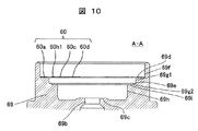
- FIG. 10 is an enlarged cross-sectional view showing the vicinity of the pilot valve portion of the damping force adjustable shock absorber according to the second embodiment of the present invention in a fail state.
- FIG. 11 is an enlarged cross-sectional view enlarging the vicinity of a pilot valve portion in a normal operation state of the damping force adjustable shock absorber according to the second embodiment of the present invention, showing a second opening state of the pilot valve portion.
- FIG. 12 is an enlarged cross-sectional view enlarging the vicinity of a pilot valve portion in a normal operation state of the damping force adjustable shock absorber according to the second embodiment of the present invention, showing a first opening state of the pilot valve portion.
- FIG. 13 is an enlarged cross-sectional view enlarging the vicinity of a pilot valve portion in a normal operation state of the damping force adjustable shock absorber according to the second embodiment of the present invention, showing the pilot valve portion closed or slightly opened. It is. 10, 12 and 13 show the AA cross section of FIG. 9, and FIG. 11 shows the BB cross section of FIG. Further, in FIGS. 11 to 14, only the pilot body 69 and the spring member 60 are shown in order to make the state of the spring member 60 easy to understand, and the description of the other pilot valve 51, the fail disc 67 and the like is omitted.
- the operation other than the spring member 60 is the same as that of the first embodiment, so the operation of the spring member 60 will be described focusing on parts different from the first embodiment.
- the contact portion between the diameter changing portion 60h3 and the second step surface 69e serves as a fulcrum, and the small diameter spring portion 60h2 of the spring member 60 is deformed downward on the inside diameter side of the contact portion. Then, the outer diameter side of the radially extending spring portion 60c abuts on the third step surface 69i (FIG. 12). Thereafter, the radially extending spring portion 60c is deformed in the lower direction centering on the inner diameter side of the contact portion between the radially extending spring portion 60c and the third step surface 69i.
- the radially extending spring portion 60c and the inner annular portion 60d are deformed so that the inner diameter side is positioned downward with respect to the outer diameter side, and a deflection (spring displacement) occurs in the radially extending spring portion 60c (see FIG. 13).
- the rigidity of the spring member 60 can be gradually increased by bringing the spring member 60 into contact with the second step surface 69 e and the third step surface 69 i in this order. That is, the spring characteristic shown in FIG. 14 can be obtained.
- the circumferentially extending spring portion 60h constitutes a first spring portion of the spring member 60
- the radially extending spring portion 60c constitutes a second spring portion of the spring member 60
- the first spring portion 60b further comprises at least It is divided into two spring parts (a first spring section 60h1 and a second spring section 60h2).
- the second step surface 69e constitutes a first restricting portion for restricting the deflection of the first spring section 60h1
- the third step surface 69i constitutes a second restricting portion for restricting the deflection of the second spring section 60h2.
- the deflection of the first spring section 60h1 is restricted by the first restricting portion 69e
- the deflection of the second spring section 60h2 is restricted by the second restricting portion 69i.
- the second spring portion 60c is bent.
- the first restricting portion 69e and the second restricting portion 69i relate to setting of the spring force, and constitute a part of a spring device.
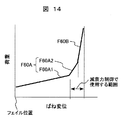
- FIG. 14 is a diagram showing the characteristics of the spring member of the second embodiment of the present invention.
- the change rate of load changes to two steps F60A1 and F60A2 with respect to the spring displacement (deflection amount of the spring). Do.
- the rate of change of load with respect to the spring displacement changes in three steps of range F60A1, range F60A2, and range F60B.
- the rate of change of the range F60A2 is larger than the rate of change of the range F60A1
- the rate of change of the range F60B is larger than the rate of change of the range F60A2.
- the first rate of change of the range F60A1 is obtained by the deflection of the first spring section 60h1
- the third rate of change of the range F60A2 is obtained by the deflection of the second spring section 60h2.
- a damping force adjustment type shock absorber for semi-active suspension a third change rate range F60A2 of the second spring section 60h2 and a second change rate range F60B of the second spring portion 60c are used in damping force control.
- the rigidity of the spring can be changed in two steps in the control region where the pilot valve opening amount is very small, and rapid pressure fluctuation can be suppressed. At the same time, vibration and noise can be suppressed, and at the same time, smooth pressure change characteristics can be obtained.
- the spring member used in the conventional damping force adjustable shock absorber can not increase the spring force in the control area after sufficiently lowering the spring force necessary for failure, and the valve body of the control valve (pilot valve) It is necessary to increase the pressure on the upstream side of the However, when the pressure on the upstream side of the valve body of the control valve is increased, rapid pressure fluctuation is likely to occur, and noise is likely to occur.
- the shock absorber includes a cylinder in which a fluid is sealed, a piston slidably fitted in the cylinder, a piston rod connected to the piston and extended to the outside of the cylinder, and a cylinder And a control valve that controls the flow of fluid generated by the movement of the piston therein to generate a damping force.
- the control valve includes a valve body, a valve seat that cooperates with the valve body to form an opening and closing portion of the flow path, an actuator that generates a force to move the valve body in response to current, and the valve body is moved by the actuator And a spring device biased in a direction opposite to the direction.
- the spring device has a spring member acting over the entire range in which the valve body moves, and a regulating member which limits the deflection of a part of the spring member against the predetermined deflection or more of the spring member.
- the spring member includes an outer annular portion, an inner annular portion, a radial direction spring portion connected to the inner annular portion and extending in the radial direction, one end connected to the outer annular portion, and the other end on the outer peripheral side of the radial direction spring portion And a circumferential spring portion connected to the The circumferential spring portion has a shape in which the inner diameter on the side connected to the outer annular portion is larger than the outer diameter of the outermost diameter portion of the radial spring portion.
- damping force adjustment type shock absorber it is possible to increase the spring force in the control region while sufficiently reducing the spring force necessary for failure, thereby suppressing rapid pressure fluctuation. It can be a low noise damping force adjustable shock absorber.
- the present invention is not limited to the above-described embodiments, but includes various modifications.
- the embodiments described above are described in detail in order to explain the present invention in an easy-to-understand manner, and are not necessarily limited to those having all the configurations.
- part of the configuration of one embodiment can be replaced with the configuration of another embodiment, and the configuration of another embodiment can be added to the configuration of one embodiment.
Abstract
L'objectif de la présente invention est de fournir un amortisseur avec lequel la puissance de ressort d'un élément ressort, qui pousse un corps de soupape dans une soupape de commande, peut être réglée plus librement. Cet amortisseur comprend une soupape de commande qui commande l'écoulement de fluide généré à l'intérieur d'un cylindre au moyen du mouvement d'un piston monté coulissant à l'intérieur du cylindre et qui génère une force d'amortissement. La soupape de commande possède : un corps de soupape et un siège de soupape qui, conjointement, forment une section d'ouverture et de fermeture d'un circuit d'écoulement ; un actionneur qui génère une force qui déplace le corps de soupape en réponse à un courant électrique ; un dispositif à ressort (60) qui pousse le corps de soupape dans la direction opposée à la direction dans laquelle l'actionneur déplace le corps de soupape. Le dispositif à ressort possède : un élément ressort (60) ayant une première section de ressort (60b) et une seconde section de ressort (60c) ; une section de limitation qui limite le déplacement de ressort de la première section de ressort (60b) par rapport à au moins un déplacement de ressort prescrit de l'élément ressort (60).
Applications Claiming Priority (2)
| Application Number | Priority Date | Filing Date | Title |
|---|---|---|---|
| JP2017131721A JP6909077B2 (ja) | 2017-07-05 | 2017-07-05 | 緩衝器 |
| JP2017-131721 | 2017-07-05 |
Publications (1)
| Publication Number | Publication Date |
|---|---|
| WO2019008902A1 true WO2019008902A1 (fr) | 2019-01-10 |
Family
ID=64949926
Family Applications (1)
| Application Number | Title | Priority Date | Filing Date |
|---|---|---|---|
| PCT/JP2018/018496 WO2019008902A1 (fr) | 2017-07-05 | 2018-05-14 | Amortisseur |
Country Status (2)
| Country | Link |
|---|---|
| JP (1) | JP6909077B2 (fr) |
| WO (1) | WO2019008902A1 (fr) |
Cited By (2)
| Publication number | Priority date | Publication date | Assignee | Title |
|---|---|---|---|---|
| US20220234408A1 (en) * | 2021-01-28 | 2022-07-28 | Volvo Car Corporation | Limiting vehicle damper jerk |
| JP7142824B1 (ja) * | 2022-04-22 | 2022-09-28 | 正裕 井尻 | 車両用アクティブサスペンション装置 |
Families Citing this family (3)
| Publication number | Priority date | Publication date | Assignee | Title |
|---|---|---|---|---|
| JP2021173303A (ja) * | 2020-04-22 | 2021-11-01 | 日立Astemo株式会社 | バルブ駆動装置及びこれを用いた緩衝器 |
| WO2022065279A1 (fr) * | 2020-09-24 | 2022-03-31 | 日立Astemo株式会社 | Dispositif de vanne de commande et amortisseur |
| JPWO2023084896A1 (fr) * | 2021-11-10 | 2023-05-19 |
Citations (3)
| Publication number | Priority date | Publication date | Assignee | Title |
|---|---|---|---|---|
| US4771808A (en) * | 1986-09-19 | 1988-09-20 | Alexander Controls Limited | Apparatus for controlling the flow of gas |
| EP1536169A1 (fr) * | 2003-11-29 | 2005-06-01 | Asco Joucomatic GmbH | Soupape électromagnétique |
| JP2014199076A (ja) * | 2013-03-29 | 2014-10-23 | 日立オートモティブシステムズ株式会社 | 緩衝器 |
-
2017
- 2017-07-05 JP JP2017131721A patent/JP6909077B2/ja active Active
-
2018
- 2018-05-14 WO PCT/JP2018/018496 patent/WO2019008902A1/fr active Application Filing
Patent Citations (3)
| Publication number | Priority date | Publication date | Assignee | Title |
|---|---|---|---|---|
| US4771808A (en) * | 1986-09-19 | 1988-09-20 | Alexander Controls Limited | Apparatus for controlling the flow of gas |
| EP1536169A1 (fr) * | 2003-11-29 | 2005-06-01 | Asco Joucomatic GmbH | Soupape électromagnétique |
| JP2014199076A (ja) * | 2013-03-29 | 2014-10-23 | 日立オートモティブシステムズ株式会社 | 緩衝器 |
Cited By (2)
| Publication number | Priority date | Publication date | Assignee | Title |
|---|---|---|---|---|
| US20220234408A1 (en) * | 2021-01-28 | 2022-07-28 | Volvo Car Corporation | Limiting vehicle damper jerk |
| JP7142824B1 (ja) * | 2022-04-22 | 2022-09-28 | 正裕 井尻 | 車両用アクティブサスペンション装置 |
Also Published As
| Publication number | Publication date |
|---|---|
| JP6909077B2 (ja) | 2021-07-28 |
| JP2019015312A (ja) | 2019-01-31 |
Similar Documents
| Publication | Publication Date | Title |
|---|---|---|
| WO2019008902A1 (fr) | Amortisseur | |
| KR102588959B1 (ko) | 완충기 | |
| JP5387841B2 (ja) | 減衰力調整式緩衝器 | |
| KR101946642B1 (ko) | 감쇠력 조정식 완충기 | |
| JP5648790B2 (ja) | 緩衝器 | |
| US8413774B2 (en) | Shock absorber | |
| US20140353099A1 (en) | Damping force control type shock absorber | |
| US11118648B2 (en) | Damping force adjustable shock absorber | |
| US20140291088A1 (en) | Shock absorber | |
| US20120273311A1 (en) | Adjustable damping valve device for a vibration damper | |
| EP2233775A1 (fr) | Amortisseur à suspension hydraulique | |
| KR20110098616A (ko) | 완충기 | |
| WO2017038571A1 (fr) | Amortisseur | |
| JP6652895B2 (ja) | 減衰力調整式緩衝器 | |
| WO2018061726A1 (fr) | Amortisseur à réglage de force d'amortissement | |
| WO2019208200A1 (fr) | Amortisseur de chocs | |
| US20150159724A1 (en) | Damping valve | |
| JP5678348B2 (ja) | 減衰力調整式緩衝器 | |
| JP6814644B2 (ja) | 減衰力調整式緩衝器 | |
| WO2020110452A1 (fr) | Soupape à amortissement | |
| US20240077126A1 (en) | Shock absorber | |
| KR20240022632A (ko) | 실린더 장치 및 제어 밸브 장치 | |
| KR20240006637A (ko) | 완충기 | |
| JP2016070421A (ja) | 緩衝器 | |
| JP2021156377A (ja) | 緩衝器 |
Legal Events
| Date | Code | Title | Description |
|---|---|---|---|
| 121 | Ep: the epo has been informed by wipo that ep was designated in this application |
Ref document number: 18827344 Country of ref document: EP Kind code of ref document: A1 |
|
| NENP | Non-entry into the national phase |
Ref country code: DE |
|
| 122 | Ep: pct application non-entry in european phase |
Ref document number: 18827344 Country of ref document: EP Kind code of ref document: A1 |