WO2019008902A1 - Shock absorber - Google Patents
Shock absorber Download PDFInfo
- Publication number
- WO2019008902A1 WO2019008902A1 PCT/JP2018/018496 JP2018018496W WO2019008902A1 WO 2019008902 A1 WO2019008902 A1 WO 2019008902A1 JP 2018018496 W JP2018018496 W JP 2018018496W WO 2019008902 A1 WO2019008902 A1 WO 2019008902A1
- Authority
- WO
- WIPO (PCT)
- Prior art keywords
- spring
- valve
- spring portion
- shock absorber
- change
- Prior art date
Links
Images


Classifications
-
- B—PERFORMING OPERATIONS; TRANSPORTING
- B60—VEHICLES IN GENERAL
- B60G—VEHICLE SUSPENSION ARRANGEMENTS
- B60G17/00—Resilient suspensions having means for adjusting the spring or vibration-damper characteristics, for regulating the distance between a supporting surface and a sprung part of vehicle or for locking suspension during use to meet varying vehicular or surface conditions, e.g. due to speed or load
- B60G17/015—Resilient suspensions having means for adjusting the spring or vibration-damper characteristics, for regulating the distance between a supporting surface and a sprung part of vehicle or for locking suspension during use to meet varying vehicular or surface conditions, e.g. due to speed or load the regulating means comprising electric or electronic elements
-
- F—MECHANICAL ENGINEERING; LIGHTING; HEATING; WEAPONS; BLASTING
- F16—ENGINEERING ELEMENTS AND UNITS; GENERAL MEASURES FOR PRODUCING AND MAINTAINING EFFECTIVE FUNCTIONING OF MACHINES OR INSTALLATIONS; THERMAL INSULATION IN GENERAL
- F16F—SPRINGS; SHOCK-ABSORBERS; MEANS FOR DAMPING VIBRATION
- F16F1/00—Springs
- F16F1/02—Springs made of steel or other material having low internal friction; Wound, torsion, leaf, cup, ring or the like springs, the material of the spring not being relevant
- F16F1/32—Belleville-type springs
-
- F—MECHANICAL ENGINEERING; LIGHTING; HEATING; WEAPONS; BLASTING
- F16—ENGINEERING ELEMENTS AND UNITS; GENERAL MEASURES FOR PRODUCING AND MAINTAINING EFFECTIVE FUNCTIONING OF MACHINES OR INSTALLATIONS; THERMAL INSULATION IN GENERAL
- F16F—SPRINGS; SHOCK-ABSORBERS; MEANS FOR DAMPING VIBRATION
- F16F9/00—Springs, vibration-dampers, shock-absorbers, or similarly-constructed movement-dampers using a fluid or the equivalent as damping medium
- F16F9/32—Details
- F16F9/34—Special valve constructions; Shape or construction of throttling passages
-
- F—MECHANICAL ENGINEERING; LIGHTING; HEATING; WEAPONS; BLASTING
- F16—ENGINEERING ELEMENTS AND UNITS; GENERAL MEASURES FOR PRODUCING AND MAINTAINING EFFECTIVE FUNCTIONING OF MACHINES OR INSTALLATIONS; THERMAL INSULATION IN GENERAL
- F16F—SPRINGS; SHOCK-ABSORBERS; MEANS FOR DAMPING VIBRATION
- F16F9/00—Springs, vibration-dampers, shock-absorbers, or similarly-constructed movement-dampers using a fluid or the equivalent as damping medium
- F16F9/32—Details
- F16F9/44—Means on or in the damper for manual or non-automatic adjustment; such means combined with temperature correction
- F16F9/46—Means on or in the damper for manual or non-automatic adjustment; such means combined with temperature correction allowing control from a distance, i.e. location of means for control input being remote from site of valves, e.g. on damper external wall
-
- F—MECHANICAL ENGINEERING; LIGHTING; HEATING; WEAPONS; BLASTING
- F16—ENGINEERING ELEMENTS AND UNITS; GENERAL MEASURES FOR PRODUCING AND MAINTAINING EFFECTIVE FUNCTIONING OF MACHINES OR INSTALLATIONS; THERMAL INSULATION IN GENERAL
- F16K—VALVES; TAPS; COCKS; ACTUATING-FLOATS; DEVICES FOR VENTING OR AERATING
- F16K31/00—Actuating devices; Operating means; Releasing devices
- F16K31/02—Actuating devices; Operating means; Releasing devices electric; magnetic
- F16K31/06—Actuating devices; Operating means; Releasing devices electric; magnetic using a magnet, e.g. diaphragm valves, cutting off by means of a liquid
Definitions
- the present invention relates to a shock absorber that generates a damping force for the stroke of a piston rod, and more particularly to a damping force adjustable shock absorber capable of controlling the damping force.
- a damping force adjustable shock absorber which detects a traveling state or the like and changes the operating pressure of a valve for opening and closing an oil passage provided in a piston of the shock absorber by a linear solenoid.
- Patent Document 1 the cylinder in which the hydraulic oil is enclosed and the inside of the cylinder are divided into two main oil chambers (upper cylinder chamber and lower cylinder chamber). Control the flow of hydraulic oil generated by the sliding of the piston, and the piston which is slidably fitted in the cylinder and is slidably fitted in the cylinder, the piston connected to the piston and extended to the outside of the cylinder, and the damping force is described.
- An attenuator (a shock absorber) having a mechanism to generate (a damping force generation mechanism) is described.
- the mechanism that generates the damping force is a control valve (which generates the damping force
- the main valve section the auxiliary oil chamber (back pressure chamber) that applies the back pressure in the direction to close the control valve by introducing the internal pressure of the main oil chamber on the high pressure side, and the check valve that guides the back pressure to the auxiliary oil chamber
- a pilot passage exhaust passage
- a pilot valve a pilot valve portion
- the pilot valve includes a valve body and a valve seat provided in the pilot passage, and a linear solenoid (which generates a force for moving the valve body in the closing direction in response to the current.
- An actuator and a leaf spring (spring member) for biasing the valve body in an opening direction opposite to the moving direction of the linear solenoid.
- a valve mechanism including a pilot valve (a pilot valve portion) configured as an attenuator (a shock absorber) will be referred to as a control valve.
- An object of the present invention is to provide a shock absorber having an improved degree of freedom in setting a spring force of a spring member for biasing a valve body of a control valve.
- the shock absorber of the present invention is A cylinder in which fluid is enclosed, a piston slidably fitted inside the cylinder, and a control valve for controlling the flow of fluid generated inside the cylinder by the movement of the piston to generate a damping force
- the control valve includes a valve body, a valve seat that cooperates with the valve body to form an opening and closing portion of a flow path, an actuator that generates a force to move the valve body in response to current, and the valve body
- a spring device which biases the spring in a direction opposite to the direction of movement by the actuator;
- the spring device has a spring member having a first spring portion and a second spring portion, and a restricting portion that restricts the spring displacement of the first spring portion against a predetermined or more spring displacement of the spring member.
- the spring member includes an outer annular portion, an inner annular portion, a radially extending spring portion connected to the inner annular portion and extending in the radial direction, and one end connected to the outer annular portion and the other end extending in the radial direction A circumferentially extending spring portion connected to an outer peripheral side of the installation spring portion;
- the circumferentially extending spring portion constitutes the first spring portion
- the radially extending spring portion constitutes the second spring portion, At least one pair of the circumferentially extending spring portion and the radially extending spring portion;
- the inner diameter of the side of the circumferentially extending spring portion connected to the outer annular portion is larger than the outer diameter of the radially extending spring portion,
- One of the radially extending spring portions of the pair of radially extending spring portions is provided in a range of a central angle overlapping with the circumferentially extending spring portion to which the other radially extending spring portion is connected.
- the present invention it is possible to increase the spring force of the control area while sufficiently lowering the spring force required for failure, thereby setting the spring force of the spring member that biases the valve body of the control valve. It is possible to provide a shock absorber with an increased degree of freedom.
- FIG. 1 is a hydraulic circuit diagram of a semi-active suspension to which the present invention is applied.
- FIG. 2 is a cross-sectional view of the damping force adjustable shock absorber according to the first embodiment of the present invention in a normal operation state.
- FIG. 3 is an enlarged cross-sectional view enlarging a portion in the vicinity of a pilot valve portion in a normal operation state of the damping force adjustable shock absorber shown in FIG. 2, showing the pilot valve portion closed or slightly opened.
- FIG. 3 is an enlarged cross-sectional view enlarging the vicinity of a pilot valve portion in a normal operation state of the damping force adjustable shock absorber shown in FIG. 2, showing a state in which the pilot valve portion is opened.
- FIG. 8 is an enlarged cross-sectional view enlarging a portion in the vicinity of a pilot valve portion in a normal operation state of the damping force adjustable shock absorber according to the second embodiment of the present invention, showing the pilot valve portion closed or slightly opened. It is a figure which shows the characteristic of the spring member of 2nd Example of this invention.
- the vertical direction may be designated to be described.
- the vertical direction is designated to make the description easy to understand, and does not necessarily coincide with the vertical direction in the mounting state of the apparatus.
- Example 1 Hereinafter, a damping force adjustable shock absorber according to a first embodiment of the present invention will be described based on the drawings.
- FIG. 1 is a hydraulic circuit diagram of a semi-active suspension to which the present invention is applied.
- the shock absorber 1 As shown in FIG. 1, the shock absorber 1 according to the present embodiment is composed of a cylinder 2, a reservoir 4, and a damping force generation mechanism 25 and is on the sprung (car body) side of the suspension device of the vehicle (not shown). Side) etc. mounted between two movable members.
- a piston 5 is slidably inserted in the cylinder 2.
- the piston 5 divides the inside of the cylinder 2 into a cylinder upper chamber (first chamber) 2A and a cylinder lower chamber (second chamber) 2B.
- a piston rod 6 is connected to the piston 5, and the end of the piston rod 6 opposite to the piston 5 passes through the cylinder upper chamber 2A, and protrudes outside the cylinder 2 through an oil seal (not shown).
- a base valve 10 for dividing the cylinder lower chamber 2B and the reservoir 4 is provided.
- the piston 5 is provided with passages 11 and 12 for communicating between the cylinder upper chamber 2A and the cylinder lower chamber 2B.
- a check valve 13 is provided which allows only fluid flow from the cylinder lower chamber 2B to the cylinder upper chamber 2A, and in the passage 11, the pressure of the fluid on the cylinder upper chamber 2A side reaches a predetermined pressure.
- a relief valve 14 is provided which relieves the fluid pressure to the cylinder lower chamber 2B side.
- the base valve 10 is provided with passages 15 and 16 which allow the cylinder lower chamber 2B and the reservoir 4 to communicate with each other.
- the non-return valve 17 which permits only the flow of fluid from the reservoir 4 to the cylinder lower chamber 2B is provided in the passage 15, and when the fluid pressure on the cylinder lower chamber 2B side reaches a predetermined pressure in the passage 16 And a relief valve 18 for relieving the fluid pressure to the reservoir 4 side.
- the damping force generation mechanism 25 has the upstream side 25 u connected to the cylinder upper chamber 2 A side, and the downstream side 25 d connected to the reservoir 4.
- FIG. 2 is a cross-sectional view of the damping force adjustable shock absorber according to the first embodiment of the present invention in a normal operating state.
- FIG. 3 is an enlarged cross-sectional view enlarging the vicinity of a pilot valve portion in a normal operation state of the damping force adjustable shock absorber shown in FIG. 2 and showing the pilot valve portion closed.
- FIG. 4 is an enlarged cross-sectional view enlarging the vicinity of a pilot valve portion in a normal operation state of the damping force adjustable shock absorber shown in FIG. 2 and a view showing a state where the pilot valve portion is opened.
- FIG. 5 is a view showing a fail state in an enlarged sectional view in which the vicinity of the pilot valve portion of the damping force adjustable shock absorber shown in FIG. 2 is enlarged.
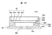
- FIG. 2 shows the entire configuration of the damping force generation mechanism 25 and FIGS. 3 to 5 show the configuration in which the vicinity of the pilot valve portion and the fail valve portion is enlarged.
- FIG. 2 shows the entire configuration of the damping force generation mechanism 25 and FIGS. 3 to 5 show the configuration in which the vicinity of the pilot valve portion and the fail valve portion is enlarged.
- FIG. 2 shows the entire configuration of the damping force generation mechanism 25 and FIGS. 3 to 5 show the configuration in which the vicinity of the pilot valve portion and the fail valve portion is enlarged.
- FIG. 2 shows the entire configuration of the damping force generation mechanism 25 and FIGS. 3 to 5 show the configuration in which the vicinity of the pilot valve portion and the fail valve portion is enlarged.
- FIG. 2 and 3 shows the state in which the pilot valve portion 28 is closed or slightly opened in a normal operation state in which current is supplied.
- the cylinder 2 is formed in a cylindrical shape in which the piston 5 can slide inside, and a separator tube 20 is provided on the outer side (peripheral side) of the cylinder 2.
- An annular passage 21 is formed between the side wall of the cylinder 2 and the separator tube 20, and the annular passage 21 communicates with the cylinder upper chamber 2A.
- the branch pipe 23 is formed in a cylindrical shape, and constitutes a substantially cylindrical separator tube opening.
- the outer cylinder 3 is provided on the outer side (outer peripheral side) of the cylinder 2 and the separator tube 20, and the annular reservoir 4 is formed between the cylinder 2 and the outer cylinder 3 .
- An annular opening 24 is provided on the side wall of the outer cylinder 3 so as to face the branch pipe 23.
- the opening 24 has a diameter larger than that of the branch pipe 23 and is disposed concentrically with the branch pipe 23.
- a damping force generation mechanism 25 is attached to the side wall of the outer cylinder 3 by welding or the like so as to face the branch pipe 23 and the opening 24.
- the separator tube opening (branch pipe 23) is not a branch pipe structure that protrudes radially outward from the separator tube 20 and is communicated with the reservoir 4, and may be a simple opening.
- the damping force generation mechanism 25 has a substantially cylindrical case 26 attached so as to cover the opening 24 of the outer cylinder 3, a pilot-type main valve portion 27 provided therein and an opening of the main valve portion 27.
- the pilot valve unit 28 is a solenoid-operated pressure control valve that controls the valve pressure, and a fail valve unit 29 located further downstream of the pilot valve unit 28 and operated at the time of failure.
- valve portion constituted by the pilot valve portion 28 and the fail valve portion 29 or the valve portion constituted by the pilot valve portion 28, the fail valve portion 29 and the main valve portion 27 It functions as an "assembly.” Therefore, the pilot valve portion 28 and the fail valve portion 29 are put together to form a "control valve assembly", and the pilot valve portion 28, the fail valve portion 29, and the main valve portion 27 are put together. It may be referred to as “control valve assembly”. The "control valve assembly” may also be referred to simply as the "control valve”.
- the case 26 is formed in a cylindrical shape with a bottom, and an opening 33 connected to the opening 24 of the outer cylinder 3 with a diameter larger than that of the branch pipe 23 of the separator tube 20 is formed in the bottom 26a. It is fixed by welding etc.
- the passage member 30, the main body 36 forming the seat portion 36c of the main valve portion 27, and the flow path between the main body 36 and the main body 36 are sequentially opened from the bottom portion 26a side (the outer cylinder 3 side)
- a valve 39, a pilot pin 37 forming a pilot passage 37b, and a pilot body 69 in which a pilot valve portion 28 and the like are provided are housed.
- a linear solenoid portion 154 for driving the pilot valve portion 28 is screwed to the opening of the case 26 by a nut 52.
- the passage member 30 has a shape in which the flange portion 30 b is formed on the outer periphery of one end of the cylindrical portion 30 a, and the cylindrical portion 30 a is fluidly fitted in the branch pipe 23 of the separator tube 20. Between the bottom 26a of the and the main body 36 and fixed. A groove 26b is provided in the case bottom 26a, and the outer peripheral side of the main body 36 and the reservoir 4 are in communication.
- the main body 36 has a substantially cylindrical shape with a recess 36d at one end side (passage member 30 side), an annular groove 36e forming a liquid chamber 57 at the other end, and a convex portion outside the groove 36e.
- the seat portion 36c on which the main valve 39 is seated is formed.
- a cylindrical pilot pin 37 is inserted at the center of the annular groove portion 36e of the main body 36, and a central hole 36a forming a pilot passage is provided.
- One end side of the main body 36 sandwiches the passage member 30 with the bottom 26 a of the case 26.
- the fluid chamber 57 is connected to and communicated with the reservoir 4 side, and is a “reservoir-side region” located on the downstream side of the main valve 39 in a fluid view.
- the upstream side of the main valve 39 is connected to and communicated with the cylinder 2 side through the opening 30, and is a "cylinder side region" located on the upstream side of the main valve 39 in a fluid view.
- a plurality of communication holes 36 b are provided between the recess 36 d at one end of the main body 36 and the annular groove 36 e at the other end.
- the pilot pin 37 is formed in a cylindrical shape having a communication passage 37b having a throttle 37a at its center, and a large diameter portion 37c projecting radially outward at an intermediate portion, one end side of which is inserted into the main body 36 The end side is fitted in the center hole 36 a of the pilot body 69.
- the outer diameter (outer peripheral surface side) of the pilot body 69 is smaller than the inner diameter of the case 26, and the outer diameter on the main valve portion 27 side is larger than the outer diameter on the opposite side of the main valve portion 27. Thus, it is formed in a cylindrical shape that changes with the step. Further, on the inner side of the pilot body 69, a recess 69j (FIG. 2) whose diameter changes stepwise is formed on the main valve portion 27 side, and the diameter also changes stepwise on the opposite side to the main valve portion 27. Recesses 69d to 69h (FIG. 3) are formed.
- the concave portions 69d to 69h have a large inner diameter portion (outermost inner diameter portion) 69f from the side with the large diameter (the outer diameter side).
- the inner diameter portion (middle inner diameter portion) 69g, the small inner diameter portion (innermost inner diameter portion) 69h, and the flat portion formed between the large inner diameter portion 69f and the middle inner diameter portion 69g is smaller than the first step surface 69d and the middle inner diameter portion 69g.
- a flat portion formed between the inner diameter portion 69h is referred to as a second step surface 69e.
- the large inner diameter portion 69f, the middle inner diameter portion 69g, and the small inner diameter portion 69h are formed in this order from the side opposite to the main valve portion 27 toward the back side (the main valve portion 27 side) of the recesses 69d to 69h. . Further, a small diameter communication hole 69b is provided in a portion to be a bottom portion of the concave portions 69d to 69h, and a seat portion 69c around which a pilot valve 51 is released and seated is provided.
- the large inner diameter portion 69f, the middle inner diameter portion 69g, and the small inner diameter portion 69h may be referred to as a first inner diameter portion 69f, a second inner diameter portion 69g, and a third inner diameter portion 69h in descending order of inner diameter.
- the pilot valve 51 includes a pilot valve member 95 which is a valve body, and a spring member 60 which biases the pilot valve member 95.
- the spring member 60 constitutes a spring device that biases the valve member 95 in the valve opening direction away from the seat portion 69c.
- the valve opening direction is a direction opposite to the direction in which the pilot valve member 95 moves by energization to a solenoid actuator formed of the coil 40, the operating rod 79, and the like.
- the pilot valve member 95 is separated from and seated on an annular seat portion 69 c provided on the pilot body 69 to open and close the small diameter communication hole 69 b of the pilot body 69.
- the pilot valve member 95 is formed in a substantially cylindrical shape, and communicates with the through hole 96 provided at one end side and the through hole 96 in the axial direction (opening and closing valve direction) so as to accommodate one end portion of the actuating rod 79. And an accommodation hole 97 which extends. The opening edge of the end of the accommodation hole 97 opposite to the through hole 96 is expanded.
- a valve tip 98 extending in an annular shape with a substantially triangular shape in cross section and seating on the seat 69c of the pilot body 69 is formed. Further, a flange-shaped spring receiving portion 99 extending radially outward is formed on the outer peripheral portion of the pilot valve member 95 near the other end.
- the pilot valve member 95 is elastically held by the spring member 60 so as to be axially movable so as to face the seat portion 69 c around the small diameter communication hole 69 b of the pilot body 69.
- the spring member 60 which comprises a spring apparatus is comprised by the thin disk-shaped member.
- the spring member 60 has a spring function for returning the pilot valve 36 (pilot valve member 95) to the fail position and a spring function for controlling the lift amount of the pilot valve 36.
- the spring member 60 has the outer annular portion 60a disposed on the first step surface 69d of the pilot body 69, one end of the pilot valve member 95 is inserted into the through hole 60e of the inner annular portion 60d, and the inner annular portion 60d is a spring. It abuts on one end surface of the receiving portion 99. Further, on the other end face side of the spring receiving portion 99, a plurality of fail disks 67 constituting the fail valve portion 29 are stacked. The fail disk 67 is stacked on the upper side of the spring member 60 (the side opposite to the seat portion 69 c) via the washer 66. As a result, the outer peripheral portions of the washer 66 and the fail disks 67 are respectively superimposed on the outer annular portion 60 a of the spring member 60.
- each fail disk 67 In the fail state, the lower surface of the inner peripheral portion of each fail disk 67 is in contact with the other end surface of the spring receiving portion 99. Further, the retainer 64 and the spacer 62 are superimposed on the outer peripheral portion of each fail disk 67, and the movement of the pilot body 69 is restricted by the holding plate 61 and the cap 49.
- the spring member 60 has a belt-like outer annular portion 60a annularly extending radially outward (peripheral side), an inner annular portion 60d annularly extending in a belt-like central portion, and a diameter from an outer periphery of the inner annular portion 60d.
- a pair of radially extending spring portions 60c extending in opposite directions toward the outward direction and a circumferential direction in the form of a strip from a portion (a portion where the angular position differs by 180 °) opposed by the inner peripheral surface of the outer annular portion 60a.
- circumferentially extending spring portions 60b respectively connected to the tips of the pair of radially extending spring portions 60c.
- the inner periphery of the inner annular portion 60d constitutes a through hole 60e.
- the outer diameter D60a of the outer annular portion 60a substantially matches the inner diameter D69f of the large inner diameter portion 69f of the recessed portions 69d to 69h of the pilot body 69, and is slightly smaller than the inner diameter D69f.
- the inner diameter D60di of the inner annular portion 60d substantially matches the outer diameter D95 of the pilot valve member 95 and is slightly larger than the outer diameter D95.
- the outer diameter D60do of the inner annular portion 60d is set to be larger than the outer diameter D99 of the spring receiving portion 99 of the pilot valve member 95.
- Each circumferentially extending spring portion 60b is extended between the outer annular portion 60a and the pair of radially extending spring portions 60c, and between each circumferentially extending spring portion 60b and the outer annular portion 60a.
- Each outer gap 60f is formed.
- an inner gap 60g is formed between each circumferentially extending spring portion 60b and the inner annular portion 60d.
- the inner gap 60g serves as a fluid channel.
- Each outer gap 60f is formed narrower than each inner gap 60g.
- the width of each circumferentially extending spring portion 60b is set narrower than the width of the outer annular portion 60a. Further, the width of each radially extending spring portion 60c is set wider than the width of each circumferentially extending spring portion 60b.
- the outer gap 60f and the inner gap 60g are formed one by one.
- One outer gap 60f communicates with one inner gap 60g
- the other outer gap 60f communicates with the other inner gap 60g.
- the one outer gap 60f and the inner gap 60g are separated from the other outer gap 60f and the inner gap 60g without communication. That is, the spring member 60 is formed by forming the two outer gaps 60 f and the two inner gaps 60 g as described above in one plate-like member.
- the number of sets of the outer gap 60f and the inner gap 60g in communication is not limited to two, and may be three or more. However, the number of sets of the outer gap 60f and the inner gap 60g is preferably two to three in order to secure the spring constant and the flow passage cross sectional area of the oil.
- each circumferential circular spring portion 60b has a circumferential direction with an outer diameter of a radius R1 smaller than the inner diameter of the outer annular portion 60a via the outer gap 60f with O1 as the center. Is extended by 90 ° at the central angle.
- the side 60b4 connected to the radially extending spring portion 60c is circumferentially connected with an outer diameter of the same radius R2 as the diameter of the outermost diameter side of the spring portion 60c, with O1 as the center.
- the outer radius is R2 and the center is from O1 to R1-R2 on the end side of 60b1
- a small diameter connecting portion 60b2 extending at a central angle of 90 ° formed eccentrically about O2 and a straight portion 60b3 linearly formed from the end of the small diameter connecting portion 60b2 are inserted, and the whole is connected It has a shape that
- the radius on the inner diameter side of the R1 portion is r1, and by setting r1 and R2 to r1> R2, the radial direction from the portion connected to the outer annular portion 60a of the circumferentially extending spring portion 60b
- the central angle to the side connected to the extending spring portion 60c can be 180 ° or more.
- the circumferentially extending spring portion 60b is provided for one or more turns, the radial dimension of the spring member 60 and the recess necessary for disposing the circumferentially extending spring portion 60b is increased. Therefore, the circumferentially extending spring portion 60b is provided.
- the central angle from the portion connected to the outer annular portion 60a to the side connected to the radially extending spring portion 60c is 360 ° or less.
- 60b is divided into 60b1 to 60b4 and connected, but instead of the method as described above, for example, connection may be made so that the outer diameter gradually changes from R1 to R2. Further, it is preferable that R2 be larger than the inner diameter D69h of the small inner diameter portion 69h, and R1 be smaller than the inner diameter D69g of the middle inner diameter portion 69g.
- the spring member 60 of the present embodiment has a side from which the circumferentially extending spring portion 60b is connected to the radially extending spring portion 60c from the one end portion (start end portion) on the side connected to the outer annular portion 60a.
- the curvature is formed to be gradually increased toward the end (end).
- the circumferentially extending spring portion 60b may be formed so that the curvature is gradually increased, or is formed so as to be continuously increased, that is, in the form of a plane curve which is spirally wound. You may Alternatively, a linear portion such as 60b3 may be provided.
- the circumferentially extending spring portion 60b is formed over an angle range of 180 ° or more at a central angle, and the beginning of one circumferentially extending spring portion 60b of the pair of circumferentially extending spring portions 60b A pair of circumferentially extending spring portions 60b is provided such that a part on the part side and a part on the terminal end side of the other circumferentially extending spring portion 60b overlap in an angle range (range of central angle) Can be placed. As a result, the degree of freedom in setting the spring force of the circumferentially extending spring portion 60b is increased.
- Each radially extending spring portion 60c corresponds to a second spring portion, and each circumferentially extending spring portion 60b corresponds to a first spring portion.
- the biasing forces of the circumferentially extending spring portions 60b of the spring member 60 and the radially extending spring portions 60c dynamically act in series.
- the spring member 60 is a spring on which a spring force acts over the entire range in which the valve body (pilot valve) 51 moves, and the load-displacement characteristic has a non-linear characteristic shown in FIG.
- FIG. 7 is a diagram showing the characteristics of the spring member of the first embodiment of the present invention.
- the load-displacement characteristic of the spring member 60 is such that, as the pilot valve 51 is in the fail position or the energization of the linear solenoid portion 154 is turned off, the load is displaced as the seat portion 69c of the pilot body 69 approaches. Amount) will increase gradually.
- the spring force of the circumferentially extending spring portion (first spring portion) 60 b acts on the pilot valve 51.
- the pilot valve member 95 further approaches the seat portion 69c and the spring displacement increases, the change in load with respect to the spring displacement rapidly increases.
- the spring force of the radially extending spring portion (second spring portion) 60 c acts on the pilot valve 51.
- the spring member 60 has a first change rate range F60A in which the load gradually changes with respect to the spring displacement, and a second change larger than the first change rate range F60A in which the load rapidly rises with respect to the spring displacement. And a range of rates F60B.
- a second change rate range F60B is used for damping force control as a damping force adjustable shock absorber for a semi-active suspension.
- the fluid corresponding to the movement of the piston 5 in the extension stroke flows from the reservoir 4 into the cylinder lower chamber 2B by opening the check valve 17 of the base valve 10.
- the relief valve 14 opens to relieve the pressure in the cylinder upper chamber 2A to the cylinder lower chamber 2B. An excessive increase in pressure of 2A can be prevented.
- the check valve 13 of the piston 5 is opened by the movement of the piston 5 in the cylinder 2 (downward in FIG. 1), and the check valve 17 of the passage 15 of the base valve 10 is closed.
- the relief valve 18 is opened, the hydraulic oil in the piston lower chamber 2B flows into the cylinder upper chamber 2A, and the fluid corresponding to the piston rod 6 entering the cylinder 2 extends from the cylinder upper chamber 2A as described above It flows to the reservoir 4 through the same path as during the stroke.
- the damping force is generated by the pilot valve portion 28 before the main valve portion 27 of the damping force generation mechanism 25 is opened (when the piston speed is in the low speed range).
- a damping force is generated according to the opening degree of the main valve portion 27.
- the damping force can be adjusted by adjusting the control pressure of the pilot valve portion 28 by the current supplied to the coil 40.
- the internal pressure of the back pressure chamber 58 changes and the main valve portion 27 opens. The valve pressure and the degree of opening can be adjusted.
- the fail disc 67 is formed of a plate-like elastic body, the fail valve portion is configured to open at a predetermined pressure. As a result, even at the time of failure, it is possible to prevent an excessive decrease in force and maintain an appropriate damping force.
- the radially extending spring portion 60c abuts on the second step surface 69e. Furthermore, since the inner diameter side of the radially extending portion 60c is in contact with the spring receiving portion 99 when the thrust of the pilot valve 51 is increased, the contact between the radially extending spring portion 60c and the second step surface 69e A portion serves as a fulcrum, and the radially extending spring portion 60c is deformed so that the inner diameter side is positioned downward with respect to the outer diameter side, and the state of FIG. 3 is reached. That is, in the state shown in FIG. 3, the radially extending spring portion 60c is bent (spring displacement).
- the radially extending spring portion 60c By setting the radially extending spring portion 60c to be thicker (wider) than the circumferentially extending spring portion 60b, a spring after the radially extending spring portion 60c and the second step surface 69e abut on each other.
- the rigidity of the member 60 can be increased. That is, the spring characteristic shown in FIG. 7 can be obtained.
- the circumferentially extending spring portion 60b can be configured to be long over a range of 180 ° or more at the central angle, it is between the rigidity of the circumferentially extending spring portion 60b and the rigidity of the radially extending spring portion 60c. Can make a big difference.
- the circumferentially extending spring portion 60b is a first spring portion of the spring member 60
- the radially extending spring portion 60c (may include the inner annular portion 60d) is a second spring portion of the spring member 60
- the second step surface 69e constitutes a restricting portion that restricts (limits) the deflection of the first spring portion 60b.
- the restricting portion 69e is related to the setting of the spring force and constitutes a part of the spring device.
- the rigidity of the spring can be enhanced in the control region where the pilot valve opening amount is very small, and it is possible to suppress the rapid pressure fluctuation and to suppress the vibration noise. Also, the degree of freedom in setting the spring force of the spring member 60 can be improved.
- the shape of the spring member 60 and the shape of the pilot body 69 are different from those of the first embodiment, and the other configuration is the same as that of the first embodiment. Therefore, in the following description, the description overlapping with that of the first embodiment is omitted.
- FIG. 8 is a cross-sectional view showing the vicinity of a pilot valve portion according to a second embodiment of the present invention, showing a fail state.
- the large inner diameter portion 69f, the first middle inner diameter portion 69g1, the second middle inner diameter portion 69g2, and the small inner diameter portion 69h are the back sides of the concave portions 69d to 69h from the side opposite to the main valve portion 27 (the main valve portion 27 side ) Are formed in this order.
- the pilot body 69 is provided with a first step surface 69d which is a flat surface formed between the large inner diameter portion 69f and the first middle inner diameter portion 69g, and a first middle inner diameter portion 69g and a second middle inner diameter portion 69h.
- a second step surface 69e which is a flat portion which can be interposed between the second step surface 69e and a third step surface 69i which is a flat portion which is formed between the second middle inner diameter portion and the small inner diameter portion are formed.
- the second inner diameter portion 69g is divided into a first middle inner diameter portion 69g1 and a second middle inner diameter portion 69g2. Be done.
- the spring member 60 has a belt-like outer annular portion 60a extending in an annular shape, an outer annular portion 60d provided in a radially central portion and a ring-like annular annular portion, and an outer periphery of the inner annular portion 60d.
- a pair of radially extending spring portions 60c extending in opposite radial directions from each other and a portion extending on the inner peripheral surface of the outer annular portion 60a in a circumferential direction respectively from a portion opposed to each other It consists of a circumferentially extending spring portion 60b connected to the tip of the spring portion 60c.
- the configuration of the circumferentially extending spring portion 60 h is different from the configuration of the circumferentially extending spring portion 60 b of the first embodiment.
- a side (large diameter spring portion) 60h1 connected to the outer annular portion 60a of each circumferential circular spring portion 60b is extended in the circumferential direction with R1 as the radius of the outer diameter and r1 as the inner radius. Ru.
- the side (small diameter spring portion) 60h2 connected to the radially extending spring portion 60c is extended in the circumferential direction with R2 being the radius of the outer diameter and r2 being the radius at the inner diameter side.
- the large diameter spring portion 60h1 has a constant outer diameter R1 and an inner diameter r1 from the end (starting end) on the side connected to the outer annular portion 60a to the end portion connected to the small diameter spring portion 60h2.
- the small diameter spring portion 60h2 has a constant outer diameter R2 and an inner diameter r2 from the end (start end) connected to the large diameter spring portion 60h1 to the end portion connected to the radially extending spring portion 60c. ing.
- a diameter changing portion 60h3 is provided at a portion where the end of the large diameter spring 60h1 and the starting end of the small diameter spring 60h2 are connected.
- the outer diameter of the diameter change portion 60h3 is R1, which is equal in size to the outer diameter of the large diameter spring portion 60h1.
- the inner diameter of the diameter change portion 60h3 is r2, which is equal in size to the inner diameter of the small diameter spring portion 60h2.
- the circumferentially extending spring portion 60h is formed by connecting the large diameter spring portion 60h1 and the small diameter spring portion 60h2 with the diameter changing portion 60h3.
- the circumferentially extending spring portion 60h can have a central angle of 180 ° or more.
- the radius D69g1 / 2 of the inner circumference of the first middle inner diameter portion 69g1 is set to be larger than R1. That is, the inner diameter D69g1 of the first middle inner diameter portion 69g1 is set to be larger than twice (2 ⁇ R1) of R1.
- the radius D69g2 / 2 of the inner circumference of the second middle inner diameter portion 69g2 is set to be smaller than R1 and larger than R2. That is, the inner diameter D69g2 of the second middle inner diameter portion 69g2 is set to be smaller than twice R1 (2 ⁇ R1) and larger than twice R2 (2 ⁇ R2).
- FIG. 10 is an enlarged cross-sectional view showing the vicinity of the pilot valve portion of the damping force adjustable shock absorber according to the second embodiment of the present invention in a fail state.
- FIG. 11 is an enlarged cross-sectional view enlarging the vicinity of a pilot valve portion in a normal operation state of the damping force adjustable shock absorber according to the second embodiment of the present invention, showing a second opening state of the pilot valve portion.
- FIG. 12 is an enlarged cross-sectional view enlarging the vicinity of a pilot valve portion in a normal operation state of the damping force adjustable shock absorber according to the second embodiment of the present invention, showing a first opening state of the pilot valve portion.
- FIG. 13 is an enlarged cross-sectional view enlarging the vicinity of a pilot valve portion in a normal operation state of the damping force adjustable shock absorber according to the second embodiment of the present invention, showing the pilot valve portion closed or slightly opened. It is. 10, 12 and 13 show the AA cross section of FIG. 9, and FIG. 11 shows the BB cross section of FIG. Further, in FIGS. 11 to 14, only the pilot body 69 and the spring member 60 are shown in order to make the state of the spring member 60 easy to understand, and the description of the other pilot valve 51, the fail disc 67 and the like is omitted.
- the operation other than the spring member 60 is the same as that of the first embodiment, so the operation of the spring member 60 will be described focusing on parts different from the first embodiment.
- the contact portion between the diameter changing portion 60h3 and the second step surface 69e serves as a fulcrum, and the small diameter spring portion 60h2 of the spring member 60 is deformed downward on the inside diameter side of the contact portion. Then, the outer diameter side of the radially extending spring portion 60c abuts on the third step surface 69i (FIG. 12). Thereafter, the radially extending spring portion 60c is deformed in the lower direction centering on the inner diameter side of the contact portion between the radially extending spring portion 60c and the third step surface 69i.
- the radially extending spring portion 60c and the inner annular portion 60d are deformed so that the inner diameter side is positioned downward with respect to the outer diameter side, and a deflection (spring displacement) occurs in the radially extending spring portion 60c (see FIG. 13).
- the rigidity of the spring member 60 can be gradually increased by bringing the spring member 60 into contact with the second step surface 69 e and the third step surface 69 i in this order. That is, the spring characteristic shown in FIG. 14 can be obtained.
- the circumferentially extending spring portion 60h constitutes a first spring portion of the spring member 60
- the radially extending spring portion 60c constitutes a second spring portion of the spring member 60
- the first spring portion 60b further comprises at least It is divided into two spring parts (a first spring section 60h1 and a second spring section 60h2).
- the second step surface 69e constitutes a first restricting portion for restricting the deflection of the first spring section 60h1
- the third step surface 69i constitutes a second restricting portion for restricting the deflection of the second spring section 60h2.
- the deflection of the first spring section 60h1 is restricted by the first restricting portion 69e
- the deflection of the second spring section 60h2 is restricted by the second restricting portion 69i.
- the second spring portion 60c is bent.
- the first restricting portion 69e and the second restricting portion 69i relate to setting of the spring force, and constitute a part of a spring device.
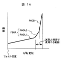
- FIG. 14 is a diagram showing the characteristics of the spring member of the second embodiment of the present invention.
- the change rate of load changes to two steps F60A1 and F60A2 with respect to the spring displacement (deflection amount of the spring). Do.
- the rate of change of load with respect to the spring displacement changes in three steps of range F60A1, range F60A2, and range F60B.
- the rate of change of the range F60A2 is larger than the rate of change of the range F60A1
- the rate of change of the range F60B is larger than the rate of change of the range F60A2.
- the first rate of change of the range F60A1 is obtained by the deflection of the first spring section 60h1
- the third rate of change of the range F60A2 is obtained by the deflection of the second spring section 60h2.
- a damping force adjustment type shock absorber for semi-active suspension a third change rate range F60A2 of the second spring section 60h2 and a second change rate range F60B of the second spring portion 60c are used in damping force control.
- the rigidity of the spring can be changed in two steps in the control region where the pilot valve opening amount is very small, and rapid pressure fluctuation can be suppressed. At the same time, vibration and noise can be suppressed, and at the same time, smooth pressure change characteristics can be obtained.
- the spring member used in the conventional damping force adjustable shock absorber can not increase the spring force in the control area after sufficiently lowering the spring force necessary for failure, and the valve body of the control valve (pilot valve) It is necessary to increase the pressure on the upstream side of the However, when the pressure on the upstream side of the valve body of the control valve is increased, rapid pressure fluctuation is likely to occur, and noise is likely to occur.
- the shock absorber includes a cylinder in which a fluid is sealed, a piston slidably fitted in the cylinder, a piston rod connected to the piston and extended to the outside of the cylinder, and a cylinder And a control valve that controls the flow of fluid generated by the movement of the piston therein to generate a damping force.
- the control valve includes a valve body, a valve seat that cooperates with the valve body to form an opening and closing portion of the flow path, an actuator that generates a force to move the valve body in response to current, and the valve body is moved by the actuator And a spring device biased in a direction opposite to the direction.
- the spring device has a spring member acting over the entire range in which the valve body moves, and a regulating member which limits the deflection of a part of the spring member against the predetermined deflection or more of the spring member.
- the spring member includes an outer annular portion, an inner annular portion, a radial direction spring portion connected to the inner annular portion and extending in the radial direction, one end connected to the outer annular portion, and the other end on the outer peripheral side of the radial direction spring portion And a circumferential spring portion connected to the The circumferential spring portion has a shape in which the inner diameter on the side connected to the outer annular portion is larger than the outer diameter of the outermost diameter portion of the radial spring portion.
- damping force adjustment type shock absorber it is possible to increase the spring force in the control region while sufficiently reducing the spring force necessary for failure, thereby suppressing rapid pressure fluctuation. It can be a low noise damping force adjustable shock absorber.
- the present invention is not limited to the above-described embodiments, but includes various modifications.
- the embodiments described above are described in detail in order to explain the present invention in an easy-to-understand manner, and are not necessarily limited to those having all the configurations.
- part of the configuration of one embodiment can be replaced with the configuration of another embodiment, and the configuration of another embodiment can be added to the configuration of one embodiment.
Abstract
The purpose of the present invention is to provide a shock absorber with which the spring strength of a spring member that impels a valve body in a control valve can be more freely set. This shock absorber comprises a control valve that: controls fluid flow generated inside a cylinder by movement of a piston slidably fitted inside the cylinder; and generates damping force. The control valve has: a valve body and a valve seat that, together, form an opening/closing section of a flow path; an actuator that generates a force that moves the valve body in response to an electric current; and a spring device (60) that impels the valve body in the direction opposite to the direction in which the actuator moves the valve body. The spring device has: a spring member (60) having a first spring section (60b) and a second spring section (60c); and a restricting section that restricts spring displacement of the first spring section (60b) relative to at least a prescribed spring displacement of the spring member (60).
Description
本発明はピストンロッドのストロークに対する減衰力を発生させる緩衝器に係り、特に減衰力を制御可能にした減衰力調整式緩衝器に関するものである。
The present invention relates to a shock absorber that generates a damping force for the stroke of a piston rod, and more particularly to a damping force adjustable shock absorber capable of controlling the damping force.
自動車等の車両に用いられる緩衝器では、走行条件によって減衰力を自由に変更できるのが望ましい。そこで、走行状態等を検出し、緩衝器のピストンに設けた油路を開閉するバルブの作動圧をリニアソレノイドによって変化させる減衰力調整式緩衝器が知られている。
In a shock absorber used for a vehicle such as a car, it is desirable that the damping force can be freely changed according to the traveling conditions. Therefore, a damping force adjustable shock absorber is known which detects a traveling state or the like and changes the operating pressure of a valve for opening and closing an oil passage provided in a piston of the shock absorber by a linear solenoid.
例えば、特開平8-170679号公報(特許文献1)の段落0013~0024には
、作動油が封入されたシリンダと、シリンダ内を2つの主油室(シリンダ上室およびシリンダ下室)に画成すると共にシリンダ内に摺動可能に嵌装されたピストンと、ピストンに連結されシリンダの外部に延出されたピストンロッドと、ピストンの摺動によって生じる作動油の流れを制御して減衰力を発生させる機構(減衰力発生機構)と、を備えた減衰器(緩衝器)が記載されている。減衰力を発生させる機構は、減衰力を発生させる制御弁(
メインバルブ部)と、高圧側の主油室の内圧が導かれ制御弁を閉じる方向に背圧を作用させる副油室(背圧室)と、副油室に背圧を導くチェック弁を備えた導入路と、背圧室の背圧を排出するパイロット通路(排出路)と、パイロット通路中に設けたパイロット弁(パイロットバルブ部)と、からなる。パイロット弁は、パイロット通路中に設けた弁体および弁座と、電流に対応して弁体を閉じ方向に移動させる力を発生するリニアソレノイド(
アクチュエータ)と、弁体をリニアソレノイドによる移動方向と対向する開き方向に付勢する板ばね(ばね部材)と、を有する。 For example, in paragraphs 0013 to 0024 of JP-A-8-170679 (Patent Document 1), the cylinder in which the hydraulic oil is enclosed and the inside of the cylinder are divided into two main oil chambers (upper cylinder chamber and lower cylinder chamber). Control the flow of hydraulic oil generated by the sliding of the piston, and the piston which is slidably fitted in the cylinder and is slidably fitted in the cylinder, the piston connected to the piston and extended to the outside of the cylinder, and the damping force is An attenuator (a shock absorber) having a mechanism to generate (a damping force generation mechanism) is described. The mechanism that generates the damping force is a control valve (which generates the damping force
The main valve section), the auxiliary oil chamber (back pressure chamber) that applies the back pressure in the direction to close the control valve by introducing the internal pressure of the main oil chamber on the high pressure side, and the check valve that guides the back pressure to the auxiliary oil chamber And a pilot passage (exhaust passage) for discharging the back pressure of the back pressure chamber, and a pilot valve (a pilot valve portion) provided in the pilot passage. The pilot valve includes a valve body and a valve seat provided in the pilot passage, and a linear solenoid (which generates a force for moving the valve body in the closing direction in response to the current.
An actuator) and a leaf spring (spring member) for biasing the valve body in an opening direction opposite to the moving direction of the linear solenoid.
特許文献1の減衰器では、故障などによりリニアソレノイド(アクチュエータ)が機能しなくなる異常時にパイロット弁(パイロットバルブ部)の弁体を完全かつ確実に開いた状態(開弁状態)に移動させる必要があるが,正常時のリニアソレノイドの消費電力を少なくするために、板ばねのばね力は小さい方が好ましい。一方で,リニアソレノイドが正常に機能する正常時(通常時)で制御する際には,騒音を抑えるために,バルブの着座付近では板ばねのばね力が大きいことが好ましい。従って、上記の板ばねのばね力に対する要求を両立することは難しい。
In the attenuator of Patent Document 1, it is necessary to move the valve body of the pilot valve (pilot valve portion) to a completely open state (open valve state) at the time of an abnormality that the linear solenoid (actuator) does not function due to failure. However, in order to reduce the power consumption of the linear solenoid during normal operation, it is preferable that the spring force of the leaf spring be small. On the other hand, it is preferable that the spring force of the leaf spring be large near the seating of the valve in order to suppress noise when performing control at normal time (normal time) in which the linear solenoid functions normally. Therefore, it is difficult to make compatible the above-mentioned demand for the spring force of the plate spring.
以下の説明では、減衰器(緩衝器)に構成される、パイロット弁(パイロットバルブ部
)を含む弁機構を、制御弁と呼んで説明する。 In the following description, a valve mechanism including a pilot valve (a pilot valve portion) configured as an attenuator (a shock absorber) will be referred to as a control valve.
)を含む弁機構を、制御弁と呼んで説明する。 In the following description, a valve mechanism including a pilot valve (a pilot valve portion) configured as an attenuator (a shock absorber) will be referred to as a control valve.
本発明の目的は、制御弁の弁体を付勢するばね部材のばね力設定の自由度を向上した緩衝器を提供することにある。
An object of the present invention is to provide a shock absorber having an improved degree of freedom in setting a spring force of a spring member for biasing a valve body of a control valve.
上記目的を達成するために、本発明の緩衝器は、
流体が封入されたシリンダと、前記シリンダの内側に摺動可能に嵌装されたピストンと
、前記ピストンの移動によって前記シリンダの内側に生じる流体の流れを制御して減衰力を発生させる制御弁と、を備え、
前記制御弁は、弁体と、前記弁体と協働して流路の開閉部を形成する弁座と、電流に対応して前記弁体を移動させる力を発生するアクチュエータと、前記弁体を前記アクチュエータによる移動方向に対向する方向に付勢するばね装置と、を有する緩衝器であって、
前記ばね装置は、第一ばね部と第二ばね部とを有するばね部材と、前記ばね部材の所定以上のばね変位に対し前記第一ばね部のばね変位を規制する規制部と、を有し、
前記ばね部材は、外側環状部と、内側環状部と、前記内側環状部と接続され径方向に延びる径方向延設ばね部と、一端が前記外側環状部に接続され他端が前記径方向延設ばね部の外周側に接続される周方向延設ばね部と、を有し、
前記周方向延設ばね部が前記第一ばね部を構成し、
前記径方向延設ばね部が前記第二ばね部を構成し、
前記周方向延設ばね部と前記径方向延設ばね部とを、それぞれ少なくとも一対ずつ備え
、
前記周方向延設ばね部の前記外側環状部に接続される側の内径は、前記径方向延設ばね部の外径よりも大きく、
一対の前記径方向延設ばね部のうち一方の径方向延設ばね部は、他方の径方向延設ばね部が接続される周方向延設ばね部と重複する中心角の範囲に設けられる。 In order to achieve the above object, the shock absorber of the present invention is
A cylinder in which fluid is enclosed, a piston slidably fitted inside the cylinder, and a control valve for controlling the flow of fluid generated inside the cylinder by the movement of the piston to generate a damping force , And
The control valve includes a valve body, a valve seat that cooperates with the valve body to form an opening and closing portion of a flow path, an actuator that generates a force to move the valve body in response to current, and the valve body A spring device which biases the spring in a direction opposite to the direction of movement by the actuator;
The spring device has a spring member having a first spring portion and a second spring portion, and a restricting portion that restricts the spring displacement of the first spring portion against a predetermined or more spring displacement of the spring member. ,
The spring member includes an outer annular portion, an inner annular portion, a radially extending spring portion connected to the inner annular portion and extending in the radial direction, and one end connected to the outer annular portion and the other end extending in the radial direction A circumferentially extending spring portion connected to an outer peripheral side of the installation spring portion;
The circumferentially extending spring portion constitutes the first spring portion,
The radially extending spring portion constitutes the second spring portion,
At least one pair of the circumferentially extending spring portion and the radially extending spring portion;
The inner diameter of the side of the circumferentially extending spring portion connected to the outer annular portion is larger than the outer diameter of the radially extending spring portion,
One of the radially extending spring portions of the pair of radially extending spring portions is provided in a range of a central angle overlapping with the circumferentially extending spring portion to which the other radially extending spring portion is connected.
本発明によれば、フェイルに必要なばね力を十分低くした上で、制御領域のばね力を高くすることができ、それによって、制御弁の弁体を付勢するばね部材のばね力設定の自由度を向上した緩衝器を提供することができる。
According to the present invention, it is possible to increase the spring force of the control area while sufficiently lowering the spring force required for failure, thereby setting the spring force of the spring member that biases the valve body of the control valve. It is possible to provide a shock absorber with an increased degree of freedom.
上記した以外の課題、構成及び効果は、以下の実施形態の説明により明らかにされる。
Problems, configurations, and effects other than those described above will be apparent from the description of the embodiments below.
本発明の実施形態について図面を用いて詳細に説明する。なお、以下の説明において、上下方向を指定して説明する場合があるが、この上下方向は説明を分かり易くするために指定するものであり、装置の実装状態における上下方向とは必ずしも一致しない。
Embodiments of the present invention will be described in detail with reference to the drawings. In the following description, the vertical direction may be designated to be described. However, the vertical direction is designated to make the description easy to understand, and does not necessarily coincide with the vertical direction in the mounting state of the apparatus.
[実施例1]
以下、本発明の第1実施例に係る減衰力調整式緩衝器を図面に基づいて説明する。 Example 1
Hereinafter, a damping force adjustable shock absorber according to a first embodiment of the present invention will be described based on the drawings.
以下、本発明の第1実施例に係る減衰力調整式緩衝器を図面に基づいて説明する。 Example 1
Hereinafter, a damping force adjustable shock absorber according to a first embodiment of the present invention will be described based on the drawings.
図1を参照して、セミアクティブサスペンション用の減衰力調整式緩衝器の全体構成について説明する。図1は、本発明が適用されるセミアクティブサスペンションの油圧回路図である。
The entire configuration of a damping force adjustable shock absorber for a semi-active suspension will be described with reference to FIG. FIG. 1 is a hydraulic circuit diagram of a semi-active suspension to which the present invention is applied.
図1に示すように、本実施例に係る緩衝器1は、シリンダ2、リザーバ4、減衰力発生機構25から構成され、図示しない車両のサスペンション装置のばね上(車体)側、ばね下(車輪側)等の相対移動可能な二部材間に装着されるものである。
As shown in FIG. 1, the shock absorber 1 according to the present embodiment is composed of a cylinder 2, a reservoir 4, and a damping force generation mechanism 25 and is on the sprung (car body) side of the suspension device of the vehicle (not shown). Side) etc. mounted between two movable members.
シリンダ2内には摺動可能にピストン5が介装され、このピストン5によりシリンダ2内がシリンダ上室(第一室)2Aとシリンダ下室(第二室)2Bとに区分されている。
A piston 5 is slidably inserted in the cylinder 2. The piston 5 divides the inside of the cylinder 2 into a cylinder upper chamber (first chamber) 2A and a cylinder lower chamber (second chamber) 2B.
ピストン5にはピストンロッド6が連結されており、ピストンロッド6のピストン5とは反対側端部は、シリンダ上室2Aを通り、図示しないオイルシールを通して、シリンダ2の外側に突出している。シリンダ2の下端側には、シリンダ下室2Bとリザーバ4を区分するベースバルブ10が設けられている。
A piston rod 6 is connected to the piston 5, and the end of the piston rod 6 opposite to the piston 5 passes through the cylinder upper chamber 2A, and protrudes outside the cylinder 2 through an oil seal (not shown). At the lower end side of the cylinder 2, a base valve 10 for dividing the cylinder lower chamber 2B and the reservoir 4 is provided.
ピストン5にはシリンダ上室2Aとシリンダ下室2Bとの間を連通させる通路11、12が設けられている。そして通路12にはシリンダ下室2Bからシリンダ上室2Aへの流体の流通のみを許容する逆止弁13が設けられ、また通路11にはシリンダ上室2A側の流体の圧力が所定圧力に達した時に開弁して、流体の圧力をシリンダ下室2B側へリリーフするリリーフ弁14が設けられている。
The piston 5 is provided with passages 11 and 12 for communicating between the cylinder upper chamber 2A and the cylinder lower chamber 2B. In the passage 12, a check valve 13 is provided which allows only fluid flow from the cylinder lower chamber 2B to the cylinder upper chamber 2A, and in the passage 11, the pressure of the fluid on the cylinder upper chamber 2A side reaches a predetermined pressure. When the valve is opened, a relief valve 14 is provided which relieves the fluid pressure to the cylinder lower chamber 2B side.
ベースバルブ10には、シリンダ下室2Bとリザーバ4とを連通させる通路15、16が設けられている。そして通路15にはリザーバ4からシリンダ下室2Bへの流体の流通のみを許容する逆止弁17が設けられ、通路16には、シリンダ下室2B側の流体の圧力が所定圧力に達したときに開弁して、流体の圧力をリザーバ4側へリリーフするリリーフ弁18が設けられている。減衰力発生機構25は、上流側25uがシリンダ上室2A側に接続され、下流側25dがリザーバ4に接続されている。
The base valve 10 is provided with passages 15 and 16 which allow the cylinder lower chamber 2B and the reservoir 4 to communicate with each other. And the non-return valve 17 which permits only the flow of fluid from the reservoir 4 to the cylinder lower chamber 2B is provided in the passage 15, and when the fluid pressure on the cylinder lower chamber 2B side reaches a predetermined pressure in the passage 16 And a relief valve 18 for relieving the fluid pressure to the reservoir 4 side. The damping force generation mechanism 25 has the upstream side 25 u connected to the cylinder upper chamber 2 A side, and the downstream side 25 d connected to the reservoir 4.
次に、減衰力発生機構25のシリンダ2への取り付け構造及び減衰力発生機構25の詳細構造について図2から図5を用いて説明する。図2は、本発明の第1実施例に係る減衰力調整式緩衝器の通常動作状態の時の断面図である。図3は、図2に示す減衰力調整式緩衝器の通常動作状態のパイロットバルブ部付近を拡大した拡大断面図でパイロットバルブ部が閉じた状態を示す図である。図4は、図2に示す減衰力調整式緩衝器の通常動作状態のパイロットバルブ部付近を拡大した拡大断面図でパイロットバルブ部が開口した状態を示す図である。図5は、図2に示す減衰力調整式緩衝器のパイロットバルブ部付近を拡大した拡大断面図でフェイル状態を示す図である。
Next, the mounting structure of the damping force generation mechanism 25 to the cylinder 2 and the detailed structure of the damping force generation mechanism 25 will be described with reference to FIGS. 2 to 5. FIG. 2 is a cross-sectional view of the damping force adjustable shock absorber according to the first embodiment of the present invention in a normal operating state. FIG. 3 is an enlarged cross-sectional view enlarging the vicinity of a pilot valve portion in a normal operation state of the damping force adjustable shock absorber shown in FIG. 2 and showing the pilot valve portion closed. FIG. 4 is an enlarged cross-sectional view enlarging the vicinity of a pilot valve portion in a normal operation state of the damping force adjustable shock absorber shown in FIG. 2 and a view showing a state where the pilot valve portion is opened. FIG. 5 is a view showing a fail state in an enlarged sectional view in which the vicinity of the pilot valve portion of the damping force adjustable shock absorber shown in FIG. 2 is enlarged.
図2は減衰力発生機構25の全体構成を示し、図3から図5はパイロットバルブ部とフェイルバルブ部付近を拡大した構成を示している。図2では、パイロットバルブ部とフェイルバルブ部付近の構成が判別しづらいので、図3から図5も併せて参照して説明する。尚、図2、図3に示す状態は通電している通常動作状態で、パイロットバルブ部28が閉弁あるいは微小に開口している図を示す。
FIG. 2 shows the entire configuration of the damping force generation mechanism 25 and FIGS. 3 to 5 show the configuration in which the vicinity of the pilot valve portion and the fail valve portion is enlarged. In FIG. 2, it is difficult to distinguish between the configuration of the pilot valve portion and the vicinity of the fail valve portion, and therefore, description will be made with reference to FIGS. 3 to 5 together. The state shown in FIGS. 2 and 3 is a diagram in which the pilot valve portion 28 is closed or slightly opened in a normal operation state in which current is supplied.
シリンダ2は内部にピストン5が摺動可能な円筒状で形成され、その外側(外周側)にセパレータチューブ20が設けられている。シリンダ2の側壁とセパレータチューブ20との間には環状通路21が形成されており、環状通路21はシリンダ上室2A側に連通されている。セパレータチューブの20の側壁には、環状通路21に連通する開口を有する小径の枝管23が突出している。枝管23は、円筒状に形成されており、略円筒状のセパレータチューブ開口を構成する。また、シリンダ2及びセパレータチューブの20の外側(外周側)には外筒3を設けた複筒構造となっており、シリンダ2と外筒3との間に環状のリザーバ4が形成されている。
The cylinder 2 is formed in a cylindrical shape in which the piston 5 can slide inside, and a separator tube 20 is provided on the outer side (peripheral side) of the cylinder 2. An annular passage 21 is formed between the side wall of the cylinder 2 and the separator tube 20, and the annular passage 21 communicates with the cylinder upper chamber 2A. On the side wall of the separator tube 20, a small diameter branch pipe 23 having an opening communicating with the annular passage 21 protrudes. The branch pipe 23 is formed in a cylindrical shape, and constitutes a substantially cylindrical separator tube opening. The outer cylinder 3 is provided on the outer side (outer peripheral side) of the cylinder 2 and the separator tube 20, and the annular reservoir 4 is formed between the cylinder 2 and the outer cylinder 3 .
外筒3の側壁には、枝管23に対向して円環状の開口24が設けられている。開口24は、枝管23よりも大径で、枝管23と同心的に配置されている。外筒3の側壁には、枝管23及び開口24に対向して減衰力発生機構25が溶接等によって取り付けられている
。尚、セパレータチューブ開口(枝管23)は、セパレータチューブ20から径方向外側に突出してリザーバ4に連通される枝管構造ではなく、単なる開口だけでも良いものである。 Anannular opening 24 is provided on the side wall of the outer cylinder 3 so as to face the branch pipe 23. The opening 24 has a diameter larger than that of the branch pipe 23 and is disposed concentrically with the branch pipe 23. A damping force generation mechanism 25 is attached to the side wall of the outer cylinder 3 by welding or the like so as to face the branch pipe 23 and the opening 24. The separator tube opening (branch pipe 23) is not a branch pipe structure that protrudes radially outward from the separator tube 20 and is communicated with the reservoir 4, and may be a simple opening.
。尚、セパレータチューブ開口(枝管23)は、セパレータチューブ20から径方向外側に突出してリザーバ4に連通される枝管構造ではなく、単なる開口だけでも良いものである。 An
減衰力発生機構25は、外筒3の開口24を覆うように取り付けられた略円筒状のケース26と、その内部に設けられた、パイロット型のメインバルブ部27と、メインバルブ部27の開弁圧力を制御するソレノイド駆動の圧力制御弁であるパイロットバルブ部28と、更にパイロットバルブ部28の下流側に位置し、フェイル時に作動するフェイルバルブ部29と、を含んで構成されている。
The damping force generation mechanism 25 has a substantially cylindrical case 26 attached so as to cover the opening 24 of the outer cylinder 3, a pilot-type main valve portion 27 provided therein and an opening of the main valve portion 27. The pilot valve unit 28 is a solenoid-operated pressure control valve that controls the valve pressure, and a fail valve unit 29 located further downstream of the pilot valve unit 28 and operated at the time of failure.
ここで、パイロットバルブ部28とフェイルバルブ部29とで構成されるバルブ部、或いはパイロットバルブ部28とフェイルバルブ部29とメインバルブ部27とで構成されるバルブ部が本実施形態では「制御弁組立体」として機能するものである。したがって、パイロットバルブ部28とフェイルバルブ部29とを合せて「制御弁組立体」とする場合と、パイロットバルブ部28とフェイルバルブ部29とメインバルブ部27とを合せて「
制御弁組立体」とする場合とがある。なお、「制御弁組立体」は単に「制御弁」と呼ぶこ
ともある。 Here, in the present embodiment, the valve portion constituted by thepilot valve portion 28 and the fail valve portion 29 or the valve portion constituted by the pilot valve portion 28, the fail valve portion 29 and the main valve portion 27 It functions as an "assembly." Therefore, the pilot valve portion 28 and the fail valve portion 29 are put together to form a "control valve assembly", and the pilot valve portion 28, the fail valve portion 29, and the main valve portion 27 are put together.
It may be referred to as "control valve assembly". The "control valve assembly" may also be referred to simply as the "control valve".
制御弁組立体」とする場合とがある。なお、「制御弁組立体」は単に「制御弁」と呼ぶこ
ともある。 Here, in the present embodiment, the valve portion constituted by the
It may be referred to as "control valve assembly". The "control valve assembly" may also be referred to simply as the "control valve".
ケース26は有底円筒状に形成され、その底部26aには、セパレータチューブ20の枝管23よりも大径で外筒3の開口24に接続する開口部33が形成されており、外筒3に溶接等により固定されている。ケース26内には、底部26a側(外筒3側)から順に
、通路部材30、メインバルブ部27のシート部36cを形成するメインボディ36、メインボディ36との間で流路を開閉するメインバルブ39、パイロット通路37bを形成するパイロットピン37、及び内部にパイロットバルブ部28などが設けられるパイロットボディ69が収納されている。そして、ケース26の開口部にパイロットバルブ部28を駆動するリニアソレノイド部154がナット52によってねじ結合されている。 Thecase 26 is formed in a cylindrical shape with a bottom, and an opening 33 connected to the opening 24 of the outer cylinder 3 with a diameter larger than that of the branch pipe 23 of the separator tube 20 is formed in the bottom 26a. It is fixed by welding etc. In the case 26, the passage member 30, the main body 36 forming the seat portion 36c of the main valve portion 27, and the flow path between the main body 36 and the main body 36 are sequentially opened from the bottom portion 26a side (the outer cylinder 3 side) A valve 39, a pilot pin 37 forming a pilot passage 37b, and a pilot body 69 in which a pilot valve portion 28 and the like are provided are housed. A linear solenoid portion 154 for driving the pilot valve portion 28 is screwed to the opening of the case 26 by a nut 52.
、通路部材30、メインバルブ部27のシート部36cを形成するメインボディ36、メインボディ36との間で流路を開閉するメインバルブ39、パイロット通路37bを形成するパイロットピン37、及び内部にパイロットバルブ部28などが設けられるパイロットボディ69が収納されている。そして、ケース26の開口部にパイロットバルブ部28を駆動するリニアソレノイド部154がナット52によってねじ結合されている。 The
通路部材30は、円筒部30aの一端部外周にフランジ部30bが形成された形状で、円筒部30aがセパレータチューブ20の枝管23内に液密的に嵌合され、フランジ部30bがケース16の底部26aとメインボディ36との間に挟持されて固定されている。尚、ケース底部26aには溝部26bが設けられており、メインボディ36の外周側とリザーバ4とが連通されている。
The passage member 30 has a shape in which the flange portion 30 b is formed on the outer periphery of one end of the cylindrical portion 30 a, and the cylindrical portion 30 a is fluidly fitted in the branch pipe 23 of the separator tube 20. Between the bottom 26a of the and the main body 36 and fixed. A groove 26b is provided in the case bottom 26a, and the outer peripheral side of the main body 36 and the reservoir 4 are in communication.
メインボディ36は、一端側(通路部材30側)が凹部36dを持った略円筒形状で、他端側には液室57を形成する円環状溝部36eを持ち、溝部36eの外側の凸部でメインバルブ39が着座するシート部36cを形成する。また、メインボディ36の円環状溝部36eの中心には円筒のパイロットピン37が挿入され、かつパイロット通路を形成する中心穴36aが設けられる。メインボディ36の一端側は、ケース26の底部26aとの間で通路部材30を挟持している。
The main body 36 has a substantially cylindrical shape with a recess 36d at one end side (passage member 30 side), an annular groove 36e forming a liquid chamber 57 at the other end, and a convex portion outside the groove 36e. The seat portion 36c on which the main valve 39 is seated is formed. Further, a cylindrical pilot pin 37 is inserted at the center of the annular groove portion 36e of the main body 36, and a central hole 36a forming a pilot passage is provided. One end side of the main body 36 sandwiches the passage member 30 with the bottom 26 a of the case 26.
液室57は、リザーバ4側に接続、連通されており、流体的に見てメインバルブ39の下流側に位置する「リザーバ側領域」となっている。一方、メインバルブ39の上流側は開口部30を介してシリンダ2側に接続、連通されており、流体的に見てメインバルブ39の上流側に位置する「シリンダ側領域」となっている。
The fluid chamber 57 is connected to and communicated with the reservoir 4 side, and is a “reservoir-side region” located on the downstream side of the main valve 39 in a fluid view. On the other hand, the upstream side of the main valve 39 is connected to and communicated with the cylinder 2 side through the opening 30, and is a "cylinder side region" located on the upstream side of the main valve 39 in a fluid view.
メインボディ36の一端側の凹部36dと他端側の円環状溝部36eとの間には複数の連通穴36bが設けられている。パイロットピン37は、中心に絞り37aをもつ連通路37bと、中間部に径方向外側に突出した大径部37cを持つ円筒形状に形成してあり、一端側はメインボディ36に挿入され、他端側はパイロットボディ69の中心穴36aに嵌装されている。
A plurality of communication holes 36 b are provided between the recess 36 d at one end of the main body 36 and the annular groove 36 e at the other end. The pilot pin 37 is formed in a cylindrical shape having a communication passage 37b having a throttle 37a at its center, and a large diameter portion 37c projecting radially outward at an intermediate portion, one end side of which is inserted into the main body 36 The end side is fitted in the center hole 36 a of the pilot body 69.
パイロットボディ69の外側(外周面側)は、外径が、ケース26の内径よりも小さく
、かつメインバルブ部27側の外径が、メインバルブ部27とは反対側の外径よりも大きくなるように、段部をもって変化する円筒形状に形成されている。また、パイロットボディ69の内側は、メインバルブ部27側には、階段状に径が変化する凹部69j(図2)が形成され、メインバルブ部27とは反対側にも階段状に径が変化する凹部69d~69h(図3)が形成されている。 The outer diameter (outer peripheral surface side) of thepilot body 69 is smaller than the inner diameter of the case 26, and the outer diameter on the main valve portion 27 side is larger than the outer diameter on the opposite side of the main valve portion 27. Thus, it is formed in a cylindrical shape that changes with the step. Further, on the inner side of the pilot body 69, a recess 69j (FIG. 2) whose diameter changes stepwise is formed on the main valve portion 27 side, and the diameter also changes stepwise on the opposite side to the main valve portion 27. Recesses 69d to 69h (FIG. 3) are formed.
、かつメインバルブ部27側の外径が、メインバルブ部27とは反対側の外径よりも大きくなるように、段部をもって変化する円筒形状に形成されている。また、パイロットボディ69の内側は、メインバルブ部27側には、階段状に径が変化する凹部69j(図2)が形成され、メインバルブ部27とは反対側にも階段状に径が変化する凹部69d~69h(図3)が形成されている。 The outer diameter (outer peripheral surface side) of the
凹部69d~69hは、径の大きい側(外径側)から、大内径部(最外内径部)69f
、中内径部(中間内径部)69g、小内径部(最内内径部)69hとし、大内径部69fと中内径部69g間にできる平面部を第一段差面69d、中内径部69gと小内径部69hの間にできる平面部を第二段差面69eとする。大内径部69f、中内径部69g、及び小内径部69hは、メインバルブ部27とは反対側から凹部69d~69hの奥側(メインバルブ部27側)に向かって、この順に形成されている。また、凹部69d~69hの底部となる部分には小径連通孔69bが設けられ、その周りにパイロットバルブ51が離着座するシート部69cが設けられている。 Theconcave portions 69d to 69h have a large inner diameter portion (outermost inner diameter portion) 69f from the side with the large diameter (the outer diameter side).
The inner diameter portion (middle inner diameter portion) 69g, the small inner diameter portion (innermost inner diameter portion) 69h, and the flat portion formed between the largeinner diameter portion 69f and the middle inner diameter portion 69g is smaller than the first step surface 69d and the middle inner diameter portion 69g. A flat portion formed between the inner diameter portion 69h is referred to as a second step surface 69e. The large inner diameter portion 69f, the middle inner diameter portion 69g, and the small inner diameter portion 69h are formed in this order from the side opposite to the main valve portion 27 toward the back side (the main valve portion 27 side) of the recesses 69d to 69h. . Further, a small diameter communication hole 69b is provided in a portion to be a bottom portion of the concave portions 69d to 69h, and a seat portion 69c around which a pilot valve 51 is released and seated is provided.
、中内径部(中間内径部)69g、小内径部(最内内径部)69hとし、大内径部69fと中内径部69g間にできる平面部を第一段差面69d、中内径部69gと小内径部69hの間にできる平面部を第二段差面69eとする。大内径部69f、中内径部69g、及び小内径部69hは、メインバルブ部27とは反対側から凹部69d~69hの奥側(メインバルブ部27側)に向かって、この順に形成されている。また、凹部69d~69hの底部となる部分には小径連通孔69bが設けられ、その周りにパイロットバルブ51が離着座するシート部69cが設けられている。 The
The inner diameter portion (middle inner diameter portion) 69g, the small inner diameter portion (innermost inner diameter portion) 69h, and the flat portion formed between the large
なお、大内径部69f、中内径部69g及び小内径部69hは、内径の大きい順に、第一内径部69f、第二内径部69g及び第三内径部69hと呼ぶ場合がある。
The large inner diameter portion 69f, the middle inner diameter portion 69g, and the small inner diameter portion 69h may be referred to as a first inner diameter portion 69f, a second inner diameter portion 69g, and a third inner diameter portion 69h in descending order of inner diameter.
パイロットバルブ51は、弁体であるパイロット弁部材95と、パイロット弁部材95を付勢するばね部材60とを備えている。ばね部材60は、弁部材95をシート部69cから離す開弁方向に付勢するばね装置を構成する。この開弁方向は、コイル40や作動ロッド79等からなるソレノイドアクチュエータへの通電によりパイロット弁部材95が移動する方向に対向する方向である。パイロット弁部材95は、パイロットボディ69に設けた環状のシート部69cに離着座してパイロットボディ69の小径連通孔69bを開閉するものである。
The pilot valve 51 includes a pilot valve member 95 which is a valve body, and a spring member 60 which biases the pilot valve member 95. The spring member 60 constitutes a spring device that biases the valve member 95 in the valve opening direction away from the seat portion 69c. The valve opening direction is a direction opposite to the direction in which the pilot valve member 95 moves by energization to a solenoid actuator formed of the coil 40, the operating rod 79, and the like. The pilot valve member 95 is separated from and seated on an annular seat portion 69 c provided on the pilot body 69 to open and close the small diameter communication hole 69 b of the pilot body 69.
パイロット弁部材95は、略円筒状に形成され、一端側に設けられる貫通孔96と、貫通孔96に連通して、作動ロッド79の一端部を収容するように軸方向(開閉弁方向)に延びる収容孔97とを有する。収容孔97の貫通孔96とは反対側端部の開口縁は拡開されている。
The pilot valve member 95 is formed in a substantially cylindrical shape, and communicates with the through hole 96 provided at one end side and the through hole 96 in the axial direction (opening and closing valve direction) so as to accommodate one end portion of the actuating rod 79. And an accommodation hole 97 which extends. The opening edge of the end of the accommodation hole 97 opposite to the through hole 96 is expanded.
パイロット弁部材95の一端面には、断面略三角形状で環状に延び、パイロットボディ69のシート部69cに離着座する弁先端部98が形成される。また、パイロット弁部材95の他端側寄りの外周部に径方向外側に延びるフランジ状のばね受部99が形成される
。パイロット弁部材95は、ばね部材60によって、パイロットボディ69の小径連通孔69b周りのシート部69cに対向して軸方向に移動可能に弾性的に保持されている。 At one end face of thepilot valve member 95, a valve tip 98 extending in an annular shape with a substantially triangular shape in cross section and seating on the seat 69c of the pilot body 69 is formed. Further, a flange-shaped spring receiving portion 99 extending radially outward is formed on the outer peripheral portion of the pilot valve member 95 near the other end. The pilot valve member 95 is elastically held by the spring member 60 so as to be axially movable so as to face the seat portion 69 c around the small diameter communication hole 69 b of the pilot body 69.
。パイロット弁部材95は、ばね部材60によって、パイロットボディ69の小径連通孔69b周りのシート部69cに対向して軸方向に移動可能に弾性的に保持されている。 At one end face of the
ばね装置を構成するばね部材60は、薄厚のディスク状部材で構成される。ばね部材60は、パイロットバルブ36(パイロット弁部材95)をフェイル位置へ戻すためのスプリング機能と、パイロットバルブ36のリフト量を制御するためのスプリング機能とを有するものである。
The spring member 60 which comprises a spring apparatus is comprised by the thin disk-shaped member. The spring member 60 has a spring function for returning the pilot valve 36 (pilot valve member 95) to the fail position and a spring function for controlling the lift amount of the pilot valve 36.
ばね部材60は外側環状部60aが、パイロットボディ69の第一段差面69d上に配置され、内側環状部60dの貫通孔60eにパイロット弁部材95の一端側が挿入されて
、内側環状部60dがばね受部99の一端面に当接される。また、ばね受部99の他端面側には、フェイルバルブ部29を構成するフェイルディスク67が複数積層されている。フェイルディスク67はワッシャ66を介してばね部材60の上側(シート部69cとは反対側)に積層されている。これにより、ばね部材60の外側環状部60a上には、ワッシャ66及び各フェイルディスク67の外周部がそれぞれ重ねられる。 Thespring member 60 has the outer annular portion 60a disposed on the first step surface 69d of the pilot body 69, one end of the pilot valve member 95 is inserted into the through hole 60e of the inner annular portion 60d, and the inner annular portion 60d is a spring. It abuts on one end surface of the receiving portion 99. Further, on the other end face side of the spring receiving portion 99, a plurality of fail disks 67 constituting the fail valve portion 29 are stacked. The fail disk 67 is stacked on the upper side of the spring member 60 (the side opposite to the seat portion 69 c) via the washer 66. As a result, the outer peripheral portions of the washer 66 and the fail disks 67 are respectively superimposed on the outer annular portion 60 a of the spring member 60.
、内側環状部60dがばね受部99の一端面に当接される。また、ばね受部99の他端面側には、フェイルバルブ部29を構成するフェイルディスク67が複数積層されている。フェイルディスク67はワッシャ66を介してばね部材60の上側(シート部69cとは反対側)に積層されている。これにより、ばね部材60の外側環状部60a上には、ワッシャ66及び各フェイルディスク67の外周部がそれぞれ重ねられる。 The
フェイル状態においては、各フェイルディスク67の内周部下面がばね受部99の他端面に当接される。さらに、各フェイルディスク67の外周部上には、リテーナ64及びスペーサ62が重ねられて、保持プレート61及びキャップ49により、パイロットボディ69の移動が規制される。
In the fail state, the lower surface of the inner peripheral portion of each fail disk 67 is in contact with the other end surface of the spring receiving portion 99. Further, the retainer 64 and the spacer 62 are superimposed on the outer peripheral portion of each fail disk 67, and the movement of the pilot body 69 is restricted by the holding plate 61 and the cap 49.
つぎに、図6を参照して、ばね部材60の形状について説明する。
Next, the shape of the spring member 60 will be described with reference to FIG.
ばね部材60は、帯状で径方向外側(外周側)を環状に延びる外側環状部60aと、径方向中央部に備えられ帯状で環状に延びる内側環状部60dと、内側環状部60dの外周から径方向外方に向かって相反する方向にそれぞれ延びる一対の径方向延設ばね部60cと、外側環状部60aの内周面で対向する部位(角度位置が180°異なる部位)から帯状でそれぞれ周方向に延び、一対の径方向延設ばね部60cの先端にそれぞれ接続される周方向延設ばね部60bとから構成される。内側環状部60dの内周は貫通孔60eを構成する。
The spring member 60 has a belt-like outer annular portion 60a annularly extending radially outward (peripheral side), an inner annular portion 60d annularly extending in a belt-like central portion, and a diameter from an outer periphery of the inner annular portion 60d. A pair of radially extending spring portions 60c extending in opposite directions toward the outward direction and a circumferential direction in the form of a strip from a portion (a portion where the angular position differs by 180 °) opposed by the inner peripheral surface of the outer annular portion 60a. And circumferentially extending spring portions 60b respectively connected to the tips of the pair of radially extending spring portions 60c. The inner periphery of the inner annular portion 60d constitutes a through hole 60e.
図5及び図6に示すように、外側環状部60aの外径D60aは、パイロットボディ69の凹部69d~69hの大内径部69fの内径D69fに略一致し、内径D69fよりもわずかに小さい。内側環状部60dの内径D60diは、パイロット弁部材95の外径D95に略一致し、外径D95よりもわずかに大きい。内側環状部60dの外径D60doは、パイロット弁部材95のばね受部99の外径D99より大径に設定される。
As shown in FIGS. 5 and 6, the outer diameter D60a of the outer annular portion 60a substantially matches the inner diameter D69f of the large inner diameter portion 69f of the recessed portions 69d to 69h of the pilot body 69, and is slightly smaller than the inner diameter D69f. The inner diameter D60di of the inner annular portion 60d substantially matches the outer diameter D95 of the pilot valve member 95 and is slightly larger than the outer diameter D95. The outer diameter D60do of the inner annular portion 60d is set to be larger than the outer diameter D99 of the spring receiving portion 99 of the pilot valve member 95.
各周方向延設ばね部60bは、外側環状部60aと、一対の径方向延設ばね部60cとの間に延設され、各周方向延設ばね部60bと外側環状部60aとの間に各外側間隙60fが形成される。一方、各周方向延設ばね部60bと内側環状部60dとの間に、内側間隙60gが形成される。内側間隙60gが油液の流路となる。各外側間隙60fは各内側間隙60gよりもその幅が狭く形成される。各周方向延設ばね部60bの幅は外側環状部60aの幅よりも狭く設定される。また、各径方向延設ばね部60cの幅は各周方向延設ばね部60bの幅よりも広く設定される。
Each circumferentially extending spring portion 60b is extended between the outer annular portion 60a and the pair of radially extending spring portions 60c, and between each circumferentially extending spring portion 60b and the outer annular portion 60a. Each outer gap 60f is formed. On the other hand, an inner gap 60g is formed between each circumferentially extending spring portion 60b and the inner annular portion 60d. The inner gap 60g serves as a fluid channel. Each outer gap 60f is formed narrower than each inner gap 60g. The width of each circumferentially extending spring portion 60b is set narrower than the width of the outer annular portion 60a. Further, the width of each radially extending spring portion 60c is set wider than the width of each circumferentially extending spring portion 60b.
外側間隙60fと内側間隙60gとは、それぞれ一つずつ形成される。一方の外側間隙60fと一方の内側間隙60gとが連通し、他方の外側間隙60fと他方の内側間隙60gとが連通する。また、一方の外側間隙60f及び内側間隙60gと他方の外側間隙60f及び内側間隙60gとは、連通せず隔絶される。すなわち、一枚の板状部材に、二つの外側間隙60fと二つの内側間隙60gとが上述のように形成されることで、ばね部材60が形成される。連通する外側間隙60fと内側間隙60gとの組数は、二組に限定される訳ではなく、三組以上であってもよい。しかし、外側間隙60fと内側間隙60gとの組数は、ばね定数及び油液の流路断面積を確保するために、2~3組とするのが好ましい
。 Theouter gap 60f and the inner gap 60g are formed one by one. One outer gap 60f communicates with one inner gap 60g, and the other outer gap 60f communicates with the other inner gap 60g. Further, the one outer gap 60f and the inner gap 60g are separated from the other outer gap 60f and the inner gap 60g without communication. That is, the spring member 60 is formed by forming the two outer gaps 60 f and the two inner gaps 60 g as described above in one plate-like member. The number of sets of the outer gap 60f and the inner gap 60g in communication is not limited to two, and may be three or more. However, the number of sets of the outer gap 60f and the inner gap 60g is preferably two to three in order to secure the spring constant and the flow passage cross sectional area of the oil.
。 The
図6を参照して、周方向円設ばね部60bの形状の詳細を説明する。
The details of the shape of the circumferential circular spring portion 60b will be described with reference to FIG.
各周方向円設ばね部60bの外側環状部60aに接続される側60b1は、O1を中心として、外側間隙60fを介して外側環状部60aの内径よりも小さい半径R1の外径にて周方向に中心角で90゜延設される。一方、径方向延設ばね部60cに接続される側60b4は、O1を中心として、ばね部60cの最外径側の径と同じ半径R2の外径にて周方向に接続される。外側環状部60aに接続される側60b1と径方向延設ばね部60cに接続される側60b4との間には、外側半径がR2で、中心がO1からR1-R2だけ60b1の端部側に偏心してO2を中心として形成される、中心角が90゜で延設される小径接続部60b2と、小径接続部60b2の端部から直線で形成される直線部60b3とが挿入され、全体が接続される形状となっている。
The side 60b1 connected to the outer annular portion 60a of each circumferential circular spring portion 60b has a circumferential direction with an outer diameter of a radius R1 smaller than the inner diameter of the outer annular portion 60a via the outer gap 60f with O1 as the center. Is extended by 90 ° at the central angle. On the other hand, the side 60b4 connected to the radially extending spring portion 60c is circumferentially connected with an outer diameter of the same radius R2 as the diameter of the outermost diameter side of the spring portion 60c, with O1 as the center. Between the side 60b1 connected to the outer annular portion 60a and the side 60b4 connected to the radially extending spring portion 60c, the outer radius is R2 and the center is from O1 to R1-R2 on the end side of 60b1 A small diameter connecting portion 60b2 extending at a central angle of 90 ° formed eccentrically about O2 and a straight portion 60b3 linearly formed from the end of the small diameter connecting portion 60b2 are inserted, and the whole is connected It has a shape that
この際、R1の部分の内径側の半径はr1とし、このr1とR2とがr1>R2とすることにより、周方向延設ばね部60bの外側環状部60aに接続される部分から、径方向
延設ばね部60cに接続される側までの中心角は180゜以上とすることができる。なお
、周方向延設ばね部60bを一周以上設けると、周方向延設ばね部60bを配置するために必要なばね部材60及び凹部の径方向寸法が大きくなるので、周方向延設ばね部60bの外側環状部60aに接続される部分から、径方向延設ばね部60cに接続される側まで
の中心角は360゜以下とすることが好ましい。 At this time, the radius on the inner diameter side of the R1 portion is r1, and by setting r1 and R2 to r1> R2, the radial direction from the portion connected to the outerannular portion 60a of the circumferentially extending spring portion 60b The central angle to the side connected to the extending spring portion 60c can be 180 ° or more. When the circumferentially extending spring portion 60b is provided for one or more turns, the radial dimension of the spring member 60 and the recess necessary for disposing the circumferentially extending spring portion 60b is increased. Therefore, the circumferentially extending spring portion 60b is provided. Preferably, the central angle from the portion connected to the outer annular portion 60a to the side connected to the radially extending spring portion 60c is 360 ° or less.
延設ばね部60cに接続される側までの中心角は180゜以上とすることができる。なお
、周方向延設ばね部60bを一周以上設けると、周方向延設ばね部60bを配置するために必要なばね部材60及び凹部の径方向寸法が大きくなるので、周方向延設ばね部60bの外側環状部60aに接続される部分から、径方向延設ばね部60cに接続される側まで
の中心角は360゜以下とすることが好ましい。 At this time, the radius on the inner diameter side of the R1 portion is r1, and by setting r1 and R2 to r1> R2, the radial direction from the portion connected to the outer
ここでは60bを60b1~60b4に分割して接続するようにしたが、上記のような方法ではなく、たとえば徐々に外径がR1からR2に変わるようにつなげるなどとしてもよい。また各半径の関係は、小内径部69hの内径D69hよりもR2が大きく、中内径部69gの内径D69gよりもR1が小さくなるようにするとよい。
Here, 60b is divided into 60b1 to 60b4 and connected, but instead of the method as described above, for example, connection may be made so that the outer diameter gradually changes from R1 to R2. Further, it is preferable that R2 be larger than the inner diameter D69h of the small inner diameter portion 69h, and R1 be smaller than the inner diameter D69g of the middle inner diameter portion 69g.
本実施例のばね部材60は、周方向延設ばね部60bが、外側環状部60aに接続される側の一端部(始端部)から、径方向延設ばね部60cに接続される側の他端部(終端部
)に向かって、曲率が次第に大きくなるように形成される。周方向延設ばね部60bは、上述したように、曲率が段階的に大きくなるように形成してもよいし、連続的に大きくなるように、すなわち螺旋状に巻いた平面曲線の形に形成してもよい。或いは、60b3のような直線部を設けてもよい。本実施例では、周方向延設ばね部60bを中心角で180°以上の角度範囲に亘って形成し、一対の周方向延設ばね部60bのうち一方の周方向延設ばね部60bの始端部側の一部と、他方の周方向延設ばね部60bの終端部側の一部とが重複する角度範囲(中心角の範囲)に存在するように、一対の周方向延設ばね部60bを配置することができる。これにより、周方向延設ばね部60bのばね力の設定の自由度が高まる。 Thespring member 60 of the present embodiment has a side from which the circumferentially extending spring portion 60b is connected to the radially extending spring portion 60c from the one end portion (start end portion) on the side connected to the outer annular portion 60a. The curvature is formed to be gradually increased toward the end (end). As described above, the circumferentially extending spring portion 60b may be formed so that the curvature is gradually increased, or is formed so as to be continuously increased, that is, in the form of a plane curve which is spirally wound. You may Alternatively, a linear portion such as 60b3 may be provided. In this embodiment, the circumferentially extending spring portion 60b is formed over an angle range of 180 ° or more at a central angle, and the beginning of one circumferentially extending spring portion 60b of the pair of circumferentially extending spring portions 60b A pair of circumferentially extending spring portions 60b is provided such that a part on the part side and a part on the terminal end side of the other circumferentially extending spring portion 60b overlap in an angle range (range of central angle) Can be placed. As a result, the degree of freedom in setting the spring force of the circumferentially extending spring portion 60b is increased.
)に向かって、曲率が次第に大きくなるように形成される。周方向延設ばね部60bは、上述したように、曲率が段階的に大きくなるように形成してもよいし、連続的に大きくなるように、すなわち螺旋状に巻いた平面曲線の形に形成してもよい。或いは、60b3のような直線部を設けてもよい。本実施例では、周方向延設ばね部60bを中心角で180°以上の角度範囲に亘って形成し、一対の周方向延設ばね部60bのうち一方の周方向延設ばね部60bの始端部側の一部と、他方の周方向延設ばね部60bの終端部側の一部とが重複する角度範囲(中心角の範囲)に存在するように、一対の周方向延設ばね部60bを配置することができる。これにより、周方向延設ばね部60bのばね力の設定の自由度が高まる。 The
なお、各径方向延設ばね部60cが第二ばね部に相当して、各周方向延設ばね部60bが第一ばね部に相当する。そして、ばね部材60の各周方向延設ばね部60bと各径方向延設ばね部60cとは、その付勢力が力学的に直列に作用するようになる。ばね部材60は、弁体(パイロットバルブ)51が移動する全範囲でばね力が作用するばねであり、荷重-変位特性が図7に示す非線形特性を有する。
Each radially extending spring portion 60c corresponds to a second spring portion, and each circumferentially extending spring portion 60b corresponds to a first spring portion. The biasing forces of the circumferentially extending spring portions 60b of the spring member 60 and the radially extending spring portions 60c dynamically act in series. The spring member 60 is a spring on which a spring force acts over the entire range in which the valve body (pilot valve) 51 moves, and the load-displacement characteristic has a non-linear characteristic shown in FIG.
図7は、本発明の第1実施例のばね部材の特性を示す図である。
FIG. 7 is a diagram showing the characteristics of the spring member of the first embodiment of the present invention.
ばね部材60の荷重-変位特性は、パイロットバルブ51がフェイル位置にある状態又はリニアソレノイド部154の通電がオフの状態からパイロットボディ69のシート部69cに近づくに従って、荷重はばね変位(ばねの撓み量)に対して緩やかに大きくなる。この状態では、周方向延設ばね部(第一ばね部)60bのばね力がパイロットバルブ51に作用している。その後、更にパイロット弁部材95がシート部69cに近づいてばね変位が大きくなると、ばね変位に対する荷重の変化が急に大きくなる。この状態では、径方向延設ばね部(第二ばね部)60cのばね力がパイロットバルブ51に作用している。すなわちばね部材60は、ばね変位に対して荷重が緩やかに変化する第一変化率の範囲F60Aと、ばね変位に対して荷重が急激に立ち上がる、第一変化率の範囲F60Aよりも大きな第二変化率の範囲F60Bと、を有する。セミアクティブサスペンション用の減衰力調整式緩衝器としては、第二変化率の範囲F60Bを減衰力制御で使用する。
The load-displacement characteristic of the spring member 60 is such that, as the pilot valve 51 is in the fail position or the energization of the linear solenoid portion 154 is turned off, the load is displaced as the seat portion 69c of the pilot body 69 approaches. Amount) will increase gradually. In this state, the spring force of the circumferentially extending spring portion (first spring portion) 60 b acts on the pilot valve 51. Thereafter, when the pilot valve member 95 further approaches the seat portion 69c and the spring displacement increases, the change in load with respect to the spring displacement rapidly increases. In this state, the spring force of the radially extending spring portion (second spring portion) 60 c acts on the pilot valve 51. That is, the spring member 60 has a first change rate range F60A in which the load gradually changes with respect to the spring displacement, and a second change larger than the first change rate range F60A in which the load rapidly rises with respect to the spring displacement. And a range of rates F60B. A second change rate range F60B is used for damping force control as a damping force adjustable shock absorber for a semi-active suspension.
以上のような構成を備えた本実施例の減衰力調整式緩衝器の具体的な動作について説明するが、先ず通常状態の動作を図1乃至図3を用いて説明する。
The specific operation of the damping force adjustable shock absorber of the present embodiment having the above configuration will be described. First, the operation in the normal state will be described using FIGS. 1 to 3.
図1に示すように、ピストンロッド6の伸び行程時には、シリンダ2内のピストン5の移動(図1において上方向)によって、ピストン5の逆止弁13が閉じ、リリーフ弁14の開弁前にはシリンダ上室2A側の作動油が加圧されるので、作動油は環状通路21を通ってセパレータチューブ20の枝管23から減衰力発生機構25の通路部材30へ流入する。
As shown in FIG. 1, during the extension stroke of the piston rod 6, the check valve 13 of the piston 5 is closed by the movement of the piston 5 in the cylinder 2 (upward in FIG. 1), and before the relief valve 14 is opened. Since the hydraulic oil on the cylinder upper chamber 2A side is pressurized, the hydraulic oil flows from the branch pipe 23 of the separator tube 20 to the passage member 30 of the damping force generation mechanism 25 through the annular passage 21.
そして、図2に示すように、通路部材30から流入した作動油は、メインバルブ部27
、パイロットバルブ部28を通って、実線で示す流線F1及び破線で示す流線F2の流れに沿ってケース26で囲まれた液室57へ流れ、更に、ケース26の端部の空間(通路溝
)26b及び外筒3の開口24を通ってリザーバ4へ流入する。 Then, as shown in FIG.
And flows through thepilot valve portion 28 along the flow of the streamline F1 shown by the solid line and the streamline F2 shown by the broken line to the fluid chamber 57 surrounded by the case 26 and further the space at the end of the case 26 It flows into the reservoir 4 through the groove 26 b and the opening 24 of the outer cylinder 3.
、パイロットバルブ部28を通って、実線で示す流線F1及び破線で示す流線F2の流れに沿ってケース26で囲まれた液室57へ流れ、更に、ケース26の端部の空間(通路溝
)26b及び外筒3の開口24を通ってリザーバ4へ流入する。 Then, as shown in FIG.
And flows through the
このとき、図1にあるようにピストン5が伸び行程で移動した分の流体が、リザーバ4からベースバルブ10の逆止弁17を開いてシリンダ下室2Bへ流入する。尚、シリンダ上室2Aの圧力がピストン5のリリーフ弁14の開弁圧力に達すると、リリーフ弁14が開いて、シリンダ上室2Aの圧力をシリンダ下室2Bへリリーフすることにより、シリンダ上室2Aの過度の圧力の上昇を防止することができる。
At this time, as shown in FIG. 1, the fluid corresponding to the movement of the piston 5 in the extension stroke flows from the reservoir 4 into the cylinder lower chamber 2B by opening the check valve 17 of the base valve 10. When the pressure in the cylinder upper chamber 2A reaches the opening pressure of the relief valve 14 of the piston 5, the relief valve 14 opens to relieve the pressure in the cylinder upper chamber 2A to the cylinder lower chamber 2B. An excessive increase in pressure of 2A can be prevented.
一方、ピストンロッド6の縮み行程時には、シリンダ2内のピストン5の移動(図1において下方向)によって、ピストン5の逆止弁13が開き、ベースバルブ10の通路15の逆止弁17が閉じ、リリーフ弁18の開弁前には、ピストン下室2Bの作動油がシリンダ上室2Aへ流入し、ピストンロッド6がシリンダ2内に侵入した分の流体がシリンダ上室2Aから、上述した伸び行程時と同様の経路を通ってリザーバ4へ流れる。
On the other hand, during the compression stroke of the piston rod 6, the check valve 13 of the piston 5 is opened by the movement of the piston 5 in the cylinder 2 (downward in FIG. 1), and the check valve 17 of the passage 15 of the base valve 10 is closed. Before the relief valve 18 is opened, the hydraulic oil in the piston lower chamber 2B flows into the cylinder upper chamber 2A, and the fluid corresponding to the piston rod 6 entering the cylinder 2 extends from the cylinder upper chamber 2A as described above It flows to the reservoir 4 through the same path as during the stroke.
尚、シリンダ下室2B内の圧力がベースバルブ10のリリーフ弁18の開弁圧力に達すると、リリーフ弁18が開いて、シリンダ下室2Bの圧力をリザーバ4へリリーフすることにより、シリンダ下室2Bの過度の圧力の上昇を防止することができる。
When the pressure in the cylinder lower chamber 2B reaches the opening pressure of the relief valve 18 of the base valve 10, the relief valve 18 is opened to relieve the pressure in the cylinder lower chamber 2B to the reservoir 4, thereby reducing the cylinder lower chamber. An excessive increase in pressure of 2B can be prevented.
このように、ピストンロッド6の伸縮行程において、減衰力発生機構25のメインバルブ部27の開弁前(ピストン速度が低速域にある時)では、パイロットバルブ部28によって減衰力が発生し、メインバルブ部27の開弁後(ピストン速度が高速域にある時)においては、メインバルブ部27の開度に応じて減衰力が発生する。そして、コイル40への通電電流によってパイロットバルブ部28の制御圧力を調整することにより、減衰力を調整することができ、その結果、背圧室58の内圧が変化してメインバルブ部27の開弁圧力及び開度を調整することができる。
Thus, in the expansion and contraction stroke of the piston rod 6, the damping force is generated by the pilot valve portion 28 before the main valve portion 27 of the damping force generation mechanism 25 is opened (when the piston speed is in the low speed range). After the valve portion 27 is opened (when the piston speed is in the high speed range), a damping force is generated according to the opening degree of the main valve portion 27. Then, the damping force can be adjusted by adjusting the control pressure of the pilot valve portion 28 by the current supplied to the coil 40. As a result, the internal pressure of the back pressure chamber 58 changes and the main valve portion 27 opens. The valve pressure and the degree of opening can be adjusted.
次に、リニアソレノイド154の通電が停止された状態の動作を図5を用いて説明する
。 Next, an operation in a state where the energization of thelinear solenoid 154 is stopped will be described with reference to FIG.
。 Next, an operation in a state where the energization of the
例えば、信号待ち等による車両の停止、或いは制御装置の故障等により、コイル40への通電が遮断されたとき、パイロットバルブ51を閉弁する方向の力が発生せず、ばね部材60により、パイロットバルブ51を開弁する方向の力が発生する。それにより、図5のパイロットバルブ51が上方(開弁方向)に移動することで、パイロットバルブ51のばね受部99の上面がフェイルディスク67の下面に当接する。この状態では、常時開となったパイロットバルブ部28の代りに、パイロットバルブ51のばね受部99とフェイルディスク67との間の流路が閉じられ、フェイルバルブ部29が閉弁する。しかしながらフェイルディスク67は板状の弾性体で構成されることから、所定の圧力ではフェイルバルブ部は開弁するように構成される。これによりフェイル時においても力の過度の低下を防止して適度な減衰力を維持することができる。
For example, when the coil 40 is de-energized due to a stop of the vehicle due to a signal waiting or a failure of the control device, no force is generated in the direction to close the pilot valve 51 and the spring member 60 A force in the direction of opening the valve 51 is generated. As a result, the pilot valve 51 of FIG. 5 moves upward (in the valve opening direction), whereby the upper surface of the spring receiving portion 99 of the pilot valve 51 abuts on the lower surface of the fail disk 67. In this state, the flow path between the spring receiving portion 99 of the pilot valve 51 and the fail disk 67 is closed instead of the normally open pilot valve portion 28 and the fail valve portion 29 is closed. However, since the fail disc 67 is formed of a plate-like elastic body, the fail valve portion is configured to open at a predetermined pressure. As a result, even at the time of failure, it is possible to prevent an excessive decrease in force and maintain an appropriate damping force.
ここで、通電停止状態(図5)から、通電状態(図3)に至る際のばね部材60の動きについて、図3乃至図5を用いて説明する。
Here, the movement of the spring member 60 when reaching the energized state (FIG. 3) from the energized state (FIG. 5) will be described with reference to FIGS.
図5の状態でソレノイドの通電によりパイロットバルブ51に図の下方向に力が作用する。これにより、ばね受部99で当接しているばね部材60の内側環状部60dが押し下げられる。このとき、径方向延設ばね部60cは、ほぼ平行な状態を保ちながら、下方に移動し、周方向延設ばね部60bが変形することで、外側環状部60aと内側環状部60dとの間に高さの差が生じるようになり、ばね部材60は図4に示すように変形する。
In the state shown in FIG. 5, a force acts on the pilot valve 51 in the downward direction of the drawing by energization of the solenoid. As a result, the inner annular portion 60 d of the spring member 60 in contact with the spring receiving portion 99 is pushed down. At this time, the radially extending spring portion 60c moves downward while maintaining the substantially parallel state, and the circumferentially extending spring portion 60b is deformed to thereby form between the outer annular portion 60a and the inner annular portion 60d. And the spring member 60 deforms as shown in FIG.
図4の状態に至ると、径方向延設ばね部60cが第二段差面69eと当接する。さらに
、パイロットバルブ51の推力が大きくなると、径方向延設部60cの内径側がばね受部99に当接されていることから、径方向延設ばね部60cと第二段差面69eとの当接部分が支点となり、径方向延設ばね部60cは内径側が外径側に対して下方に位置するように変形し、図3の状態に至る。すなわち図3の状態では、径方向延設ばね部60cに撓み(ばね変位)が生じている。 In the state shown in FIG. 4, the radially extendingspring portion 60c abuts on the second step surface 69e. Furthermore, since the inner diameter side of the radially extending portion 60c is in contact with the spring receiving portion 99 when the thrust of the pilot valve 51 is increased, the contact between the radially extending spring portion 60c and the second step surface 69e A portion serves as a fulcrum, and the radially extending spring portion 60c is deformed so that the inner diameter side is positioned downward with respect to the outer diameter side, and the state of FIG. 3 is reached. That is, in the state shown in FIG. 3, the radially extending spring portion 60c is bent (spring displacement).
、パイロットバルブ51の推力が大きくなると、径方向延設部60cの内径側がばね受部99に当接されていることから、径方向延設ばね部60cと第二段差面69eとの当接部分が支点となり、径方向延設ばね部60cは内径側が外径側に対して下方に位置するように変形し、図3の状態に至る。すなわち図3の状態では、径方向延設ばね部60cに撓み(ばね変位)が生じている。 In the state shown in FIG. 4, the radially extending
ここで径方向延設ばね部60cを周方向延設ばね部60bよりも太く(幅広に)設定することで、径方向延設ばね部60cと第二段差面69eとが当接した後のばね部材60の剛性を高くすることができる。すなわち図7に示すばね特性とすることができる。ここで
、周方向延設ばね部60bは、中心角で180゜以上の範囲に亘って長く構成できることで、周方向延設ばね部60bの剛性と径方向延設ばね部60cの剛性との間に大きな差を持たせることができる。 Here, by setting the radially extendingspring portion 60c to be thicker (wider) than the circumferentially extending spring portion 60b, a spring after the radially extending spring portion 60c and the second step surface 69e abut on each other. The rigidity of the member 60 can be increased. That is, the spring characteristic shown in FIG. 7 can be obtained. Here, since the circumferentially extending spring portion 60b can be configured to be long over a range of 180 ° or more at the central angle, it is between the rigidity of the circumferentially extending spring portion 60b and the rigidity of the radially extending spring portion 60c. Can make a big difference.
、周方向延設ばね部60bは、中心角で180゜以上の範囲に亘って長く構成できることで、周方向延設ばね部60bの剛性と径方向延設ばね部60cの剛性との間に大きな差を持たせることができる。 Here, by setting the radially extending
本実施例では、周方向延設ばね部60bがばね部材60の第一ばね部、径方向延設ばね部60c(内側環状部60dを含めてもよい)がばね部材60の第二ばね部、第二段差面69eが第一ばね部60bの撓みを規制(制限)する規制部を構成する。この規制部69eは、ばね力の設定に関係し、ばね装置の一部を構成する。
In this embodiment, the circumferentially extending spring portion 60b is a first spring portion of the spring member 60, the radially extending spring portion 60c (may include the inner annular portion 60d) is a second spring portion of the spring member 60, The second step surface 69e constitutes a restricting portion that restricts (limits) the deflection of the first spring portion 60b. The restricting portion 69e is related to the setting of the spring force and constitutes a part of the spring device.
以上の通り、本実施例によれば、パイロットバルブ開口量が微小な制御領域においてばねの剛性を高めることができ、急激な圧力変動を抑えることが可能となり、振動騒音抑制が可能となる。また、ばね部材60のばね力設定の自由度を向上することができる。
As described above, according to the present embodiment, the rigidity of the spring can be enhanced in the control region where the pilot valve opening amount is very small, and it is possible to suppress the rapid pressure fluctuation and to suppress the vibration noise. Also, the degree of freedom in setting the spring force of the spring member 60 can be improved.
[実施例2]
つぎに、本発明の第2の実施例に係る減衰力調整式緩衝器を図面に基づいて説明する。 Example 2
Next, a damping force adjustable shock absorber according to a second embodiment of the present invention will be described based on the drawings.
つぎに、本発明の第2の実施例に係る減衰力調整式緩衝器を図面に基づいて説明する。 Example 2
Next, a damping force adjustable shock absorber according to a second embodiment of the present invention will be described based on the drawings.
本実施例では、ばね部材60の形状およびパイロットボディ69の形状が実施例1と異なり、これ以外の構成は実施例1と同様である。したがって、以下の説明では実施例1と重複する説明は省略する。
In the present embodiment, the shape of the spring member 60 and the shape of the pilot body 69 are different from those of the first embodiment, and the other configuration is the same as that of the first embodiment. Therefore, in the following description, the description overlapping with that of the first embodiment is omitted.
まず、パイロットボディ69の形状について図8を用いて説明する。図8は、本発明の第2実施例のパイロットバルブ部付近を示す断面図でフェイル状態を示す図である。
First, the shape of the pilot body 69 will be described with reference to FIG. FIG. 8 is a cross-sectional view showing the vicinity of a pilot valve portion according to a second embodiment of the present invention, showing a fail state.
図8に示すように、本実施例では、パイロットボディ69のメインバルブ部27とは反対側に設ける、階段状に径が変化する凹部69d~69hの構成が実施例1と異なる。
As shown in FIG. 8, in the present embodiment, the configuration of the recesses 69d to 69h provided on the side opposite to the main valve portion 27 of the pilot body 69 and whose diameter changes stepwise is different from that of the first embodiment.
図に示すように、階段状に外径側から大内径部69f、第1中内径部69g1、第2中内径部69g2、小内径部69hとなるように形成される。また、大内径部69f、第1中内径部69g1、第2中内径部69g2、及び小内径部69hは、メインバルブ部27とは反対側から凹部69d~69hの奥側(メインバルブ部27側)に向かって、この順に形成されている。そして、パイロットボディ69には、大内径部69fと第一中内径部69gとの間にできる平面部である第一段差面69dと、第一中内径部69gと第二中内径部69hとの間にできる平面部である第二段差面69eと、第二中内径部と小内径部との間にできる平面部である第三段差面69iと、が形成される。
As shown in the figure, it is formed stepwise from the outer diameter side so as to be a large inner diameter portion 69f, a first middle inner diameter portion 69g1, a second middle inner diameter portion 69g2, and a small inner diameter portion 69h. Further, the large inner diameter portion 69f, the first middle inner diameter portion 69g1, the second middle inner diameter portion 69g2, and the small inner diameter portion 69h are the back sides of the concave portions 69d to 69h from the side opposite to the main valve portion 27 (the main valve portion 27 side ) Are formed in this order. The pilot body 69 is provided with a first step surface 69d which is a flat surface formed between the large inner diameter portion 69f and the first middle inner diameter portion 69g, and a first middle inner diameter portion 69g and a second middle inner diameter portion 69h. A second step surface 69e which is a flat portion which can be interposed between the second step surface 69e and a third step surface 69i which is a flat portion which is formed between the second middle inner diameter portion and the small inner diameter portion are formed.
本実施例では、実施例1における第一内径部69f、第二内径部69g及び第三内径部69hにおいて、第二内径部69gが第1中内径部69g1と第2中内径部69g2とに分割される。
In the present embodiment, in the first inner diameter portion 69f, the second inner diameter portion 69g and the third inner diameter portion 69h in the first embodiment, the second inner diameter portion 69g is divided into a first middle inner diameter portion 69g1 and a second middle inner diameter portion 69g2. Be done.
また、ばね部材60は実施例1と同様に、帯状で外側を環状に延びる外側環状部60aと、径方向中央部に備えられ帯状で環状に延びる内側環状部60dと、内側環状部60dの外周から径方向外方の相反する方向にそれぞれ延びる一対の径方向延設ばね部60cと
、外側環状部60aの内周面で対向する部位から帯状でそれぞれ周方向に延び、一対の径方向延設ばね部60cの先端にそれぞれ接続される周方向延設ばね部60bとから構成される。 In the same manner as in the first embodiment, thespring member 60 has a belt-like outer annular portion 60a extending in an annular shape, an outer annular portion 60d provided in a radially central portion and a ring-like annular annular portion, and an outer periphery of the inner annular portion 60d. A pair of radially extending spring portions 60c extending in opposite radial directions from each other and a portion extending on the inner peripheral surface of the outer annular portion 60a in a circumferential direction respectively from a portion opposed to each other It consists of a circumferentially extending spring portion 60b connected to the tip of the spring portion 60c.
、外側環状部60aの内周面で対向する部位から帯状でそれぞれ周方向に延び、一対の径方向延設ばね部60cの先端にそれぞれ接続される周方向延設ばね部60bとから構成される。 In the same manner as in the first embodiment, the
ここで周方向延設ばね部60hの構成が実施例1の周方向延設ばね部60bの構成と異なる。各周方向円設ばね部60bの外側環状部60aに接続される側(大径ばね部)60h1は、外側径の半径をR1として、また内径側の半径をr1として、周方向に延設される。一方、径方向延設ばね部60cに接続される側(小径ばね部)60h2は、外側径の半径をR2として、また内径側の半径をr2として、周方向に延設される。大径ばね部60h1は、外側環状部60aに接続される側の端部(始端部)から小径ばね部60h2に接続される終端部まで、外径R1及び内径r1が一定に形成されている。小径ばね部60h2は、大径ばね部60h1に接続される側の端部(始端部)から径方向延設ばね部60cに接続される終端部まで、外径R2及び内径r2が一定に形成されている。
Here, the configuration of the circumferentially extending spring portion 60 h is different from the configuration of the circumferentially extending spring portion 60 b of the first embodiment. A side (large diameter spring portion) 60h1 connected to the outer annular portion 60a of each circumferential circular spring portion 60b is extended in the circumferential direction with R1 as the radius of the outer diameter and r1 as the inner radius. Ru. On the other hand, the side (small diameter spring portion) 60h2 connected to the radially extending spring portion 60c is extended in the circumferential direction with R2 being the radius of the outer diameter and r2 being the radius at the inner diameter side. The large diameter spring portion 60h1 has a constant outer diameter R1 and an inner diameter r1 from the end (starting end) on the side connected to the outer annular portion 60a to the end portion connected to the small diameter spring portion 60h2. The small diameter spring portion 60h2 has a constant outer diameter R2 and an inner diameter r2 from the end (start end) connected to the large diameter spring portion 60h1 to the end portion connected to the radially extending spring portion 60c. ing.
大径ばね部60h1の終端部と小径ばね部60h2の始端部とが連結される部分に径変化部60h3が設けられる。径変化部60h3の外径はR1であり、大径ばね部60h1の外径に等しい大きさである。径変化部60h3の内径はr2であり、小径ばね部60h2の内径に等しい大きさである。大径ばね部60h1と小径ばね部60h2とを径変化部60h3で接続することで、周方向延設ばね部60hが形成される。
A diameter changing portion 60h3 is provided at a portion where the end of the large diameter spring 60h1 and the starting end of the small diameter spring 60h2 are connected. The outer diameter of the diameter change portion 60h3 is R1, which is equal in size to the outer diameter of the large diameter spring portion 60h1. The inner diameter of the diameter change portion 60h3 is r2, which is equal in size to the inner diameter of the small diameter spring portion 60h2. The circumferentially extending spring portion 60h is formed by connecting the large diameter spring portion 60h1 and the small diameter spring portion 60h2 with the diameter changing portion 60h3.
ここでr1よりもR2が小さくなるように設定することで、周方向延設ばね部60hは中心角を180゜以上とすることができる。
Here, by setting R2 to be smaller than r1, the circumferentially extending spring portion 60h can have a central angle of 180 ° or more.
また、第一中内径部69g1の内周の半径D69g1/2はR1よりも大きくなるように設定する。すなわち、第一中内径部69g1の内径D69g1は、R1の2倍(2×R1)よりも大きくなるように設定する。また、第二中内径部69g2の内周の半径D69g2/2はR1よりも小さく、R2よりも大きくなるように設定する。すなわち、第二中内径部69g2の内径D69g2は、R1の2倍(2×R1)よりも小さく、R2の2倍(2×R2)よりも大きくなるように設定する。
The radius D69g1 / 2 of the inner circumference of the first middle inner diameter portion 69g1 is set to be larger than R1. That is, the inner diameter D69g1 of the first middle inner diameter portion 69g1 is set to be larger than twice (2 × R1) of R1. The radius D69g2 / 2 of the inner circumference of the second middle inner diameter portion 69g2 is set to be smaller than R1 and larger than R2. That is, the inner diameter D69g2 of the second middle inner diameter portion 69g2 is set to be smaller than twice R1 (2 × R1) and larger than twice R2 (2 × R2).
次に、本実施例の減衰力調整式緩衝器の動作について、図11乃至図14を用いて説明する。図10は、本発明の第2実施例に係る減衰力調整式緩衝器のパイロットバルブ部付近を拡大した拡大断面図でフェイル状態を示す図である。図11は、本発明の第2実施例に係る減衰力調整式緩衝器の通常動作状態のパイロットバルブ部付近を拡大した拡大断面図でパイロットバルブ部の第2の開口状態を示す図である。図12は、本発明の第2実施例に係る減衰力調整式緩衝器の通常動作状態のパイロットバルブ部付近を拡大した拡大断面図でパイロットバルブ部の第1の開口状態を示す図である。図13は、本発明の第2実施例に係る減衰力調整式緩衝器の通常動作状態のパイロットバルブ部付近を拡大した拡大断面図でパイロットバルブ部が閉弁あるいは微小に開口した状態を示す図である。なお、図10,12,13は図9のA-A断面を示し、図11は図9のB-B断面を示す。また
、図11乃至図14では、ばね部材60の状態を分かり易くするため、パイロットボディ69及びばね部材60のみを示し、その他のパイロットバルブ51やフェイルディスク67等の記載は省略している。 Next, the operation of the damping force adjustable shock absorber according to the present embodiment will be described with reference to FIGS. FIG. 10 is an enlarged cross-sectional view showing the vicinity of the pilot valve portion of the damping force adjustable shock absorber according to the second embodiment of the present invention in a fail state. FIG. 11 is an enlarged cross-sectional view enlarging the vicinity of a pilot valve portion in a normal operation state of the damping force adjustable shock absorber according to the second embodiment of the present invention, showing a second opening state of the pilot valve portion. FIG. 12 is an enlarged cross-sectional view enlarging the vicinity of a pilot valve portion in a normal operation state of the damping force adjustable shock absorber according to the second embodiment of the present invention, showing a first opening state of the pilot valve portion. FIG. 13 is an enlarged cross-sectional view enlarging the vicinity of a pilot valve portion in a normal operation state of the damping force adjustable shock absorber according to the second embodiment of the present invention, showing the pilot valve portion closed or slightly opened. It is. 10, 12 and 13 show the AA cross section of FIG. 9, and FIG. 11 shows the BB cross section of FIG. Further, in FIGS. 11 to 14, only thepilot body 69 and the spring member 60 are shown in order to make the state of the spring member 60 easy to understand, and the description of the other pilot valve 51, the fail disc 67 and the like is omitted.
、図11乃至図14では、ばね部材60の状態を分かり易くするため、パイロットボディ69及びばね部材60のみを示し、その他のパイロットバルブ51やフェイルディスク67等の記載は省略している。 Next, the operation of the damping force adjustable shock absorber according to the present embodiment will be described with reference to FIGS. FIG. 10 is an enlarged cross-sectional view showing the vicinity of the pilot valve portion of the damping force adjustable shock absorber according to the second embodiment of the present invention in a fail state. FIG. 11 is an enlarged cross-sectional view enlarging the vicinity of a pilot valve portion in a normal operation state of the damping force adjustable shock absorber according to the second embodiment of the present invention, showing a second opening state of the pilot valve portion. FIG. 12 is an enlarged cross-sectional view enlarging the vicinity of a pilot valve portion in a normal operation state of the damping force adjustable shock absorber according to the second embodiment of the present invention, showing a first opening state of the pilot valve portion. FIG. 13 is an enlarged cross-sectional view enlarging the vicinity of a pilot valve portion in a normal operation state of the damping force adjustable shock absorber according to the second embodiment of the present invention, showing the pilot valve portion closed or slightly opened. It is. 10, 12 and 13 show the AA cross section of FIG. 9, and FIG. 11 shows the BB cross section of FIG. Further, in FIGS. 11 to 14, only the
ばね部材60以外の動作は実施例1と同様であるため、ばね部材60の動作について、実施例1と異なる部分を中心に説明する。
The operation other than the spring member 60 is the same as that of the first embodiment, so the operation of the spring member 60 will be described focusing on parts different from the first embodiment.
パイロットバルブ51がフェイル位置にある状態、又はリニアソレノイド部154の通電がオフの状態では、ばね部材60はわずかに撓んだ状態である(図10)。
When the pilot valve 51 is in the fail position or when the linear solenoid unit 154 is deenergized, the spring member 60 is slightly bent (FIG. 10).
ソレノイドの通電によりパイロットバルブ51に図8の下方向に力が作用する。これにより、ばね受部99で当接しているばね部材60の内側環状部60dが押し下げられ、方向延設ばね部60cはほぼ平行な状態を保ちながら下方に移動する。このとき、周方向延設ばね部60hが変形することで、外側環状部60aと内側環状部60dとの間に高さの差(高低差)が生じるようになる。そして、径変化部60h3の外径側が第二段差面69eと当接する(図11)。
By energizing the solenoid, a force acts on the pilot valve 51 downward in FIG. As a result, the inner annular portion 60d of the spring member 60 in contact with the spring receiving portion 99 is pushed down, and the direction extending spring portion 60c moves downward while maintaining a substantially parallel state. At this time, when the circumferentially extending spring portion 60h is deformed, a height difference (height difference) is generated between the outer annular portion 60a and the inner annular portion 60d. Then, the outer diameter side of the diameter change portion 60h3 abuts on the second step surface 69e (FIG. 11).
さらに、パイロットバルブ51の推力が大きくなると、
径変化部60h3と第二段差面69eとの当接部分が支点となり、この当接部分よりも内径側を中心にばね部材60の小径ばね部60h2が下側方向に変形する。そして、径方向延設ばね部60cの外径側が第三段差面69iと当接する(図12)。その後、径方向延
設ばね部60cと第三段差面69iとの当接部分よりも内径側を中心に径方向延設ばね部60cが下側方向に変形する。すなわち、径方向延設ばね部60c及び内側環状部60dは、内径側が外径側に対して下方に位置するように変形し、径方向延設ばね部60cに撓み(ばね変位)が生じる(図13)。 Furthermore, when the thrust ofpilot valve 51 increases,
The contact portion between the diameter changing portion 60h3 and thesecond step surface 69e serves as a fulcrum, and the small diameter spring portion 60h2 of the spring member 60 is deformed downward on the inside diameter side of the contact portion. Then, the outer diameter side of the radially extending spring portion 60c abuts on the third step surface 69i (FIG. 12). Thereafter, the radially extending spring portion 60c is deformed in the lower direction centering on the inner diameter side of the contact portion between the radially extending spring portion 60c and the third step surface 69i. That is, the radially extending spring portion 60c and the inner annular portion 60d are deformed so that the inner diameter side is positioned downward with respect to the outer diameter side, and a deflection (spring displacement) occurs in the radially extending spring portion 60c (see FIG. 13).
径変化部60h3と第二段差面69eとの当接部分が支点となり、この当接部分よりも内径側を中心にばね部材60の小径ばね部60h2が下側方向に変形する。そして、径方向延設ばね部60cの外径側が第三段差面69iと当接する(図12)。その後、径方向延
設ばね部60cと第三段差面69iとの当接部分よりも内径側を中心に径方向延設ばね部60cが下側方向に変形する。すなわち、径方向延設ばね部60c及び内側環状部60dは、内径側が外径側に対して下方に位置するように変形し、径方向延設ばね部60cに撓み(ばね変位)が生じる(図13)。 Furthermore, when the thrust of
The contact portion between the diameter changing portion 60h3 and the
ばね部材60が、第二段差面69e当接、第三段差面69i当接と順に当接することで
、徐々にばね部材60の剛性を高くすることができる。すなわち図14に示すばね特性とすることができる。 The rigidity of thespring member 60 can be gradually increased by bringing the spring member 60 into contact with the second step surface 69 e and the third step surface 69 i in this order. That is, the spring characteristic shown in FIG. 14 can be obtained.
、徐々にばね部材60の剛性を高くすることができる。すなわち図14に示すばね特性とすることができる。 The rigidity of the
本実施例では、周方向延設ばね部60hがばね部材60の第一ばね部、径方向延設ばね部60cがばね部材60の第二ばね部を構成し、さらに第一ばね部60bが少なくとも二つのばね部(第一ばね区分60h1及び第二ばね区分60h2)に区分される。第二段差面69eは第一ばね区分60h1の撓みを規制する第一規制部を構成し、第三段差面69iは第二ばね区分60h2の撓みを規制する第二規制部を構成する。そして、第一ばね区分60h1の撓みが第一規制部69eにより規制された後で、第二ばね区分60h2の撓みを第二規制部69iで規制する。第二ばね区分60h2の撓みが第二規制部69iで規制された後、第二ばね部60cが撓む。
In this embodiment, the circumferentially extending spring portion 60h constitutes a first spring portion of the spring member 60, the radially extending spring portion 60c constitutes a second spring portion of the spring member 60, and the first spring portion 60b further comprises at least It is divided into two spring parts (a first spring section 60h1 and a second spring section 60h2). The second step surface 69e constitutes a first restricting portion for restricting the deflection of the first spring section 60h1, and the third step surface 69i constitutes a second restricting portion for restricting the deflection of the second spring section 60h2. Then, after the deflection of the first spring section 60h1 is restricted by the first restricting portion 69e, the deflection of the second spring section 60h2 is restricted by the second restricting portion 69i. After the deflection of the second spring section 60h2 is restricted by the second restricting portion 69i, the second spring portion 60c is bent.
第一規制部69e及び第二規制部69iは、ばね力の設定に関係し、ばね装置の一部を構成する。
The first restricting portion 69e and the second restricting portion 69i relate to setting of the spring force, and constitute a part of a spring device.
図14は、本発明の第2実施例のばね部材の特性を示す図である。
FIG. 14 is a diagram showing the characteristics of the spring member of the second embodiment of the present invention.
本実施例のばね部材60の荷重-変位特性は、実施例1の第一変化率の範囲F60Aにおいて、ばね変位(ばねの撓み量)に対して荷重の変化率が二段階F60A1,F60A2に変化する。本実施例では、ばね変位が大きくなるに従って、ばね変位に対する荷重の変化率は、範囲F60A1、範囲F60A2、範囲F60Bの三段階で変化する。またこの変化率は、範囲F60A1の変化率よりも範囲F60A2の変化率の方が大きく、範囲F60A2の変化率よりも範囲F60Bの変化率の方が更に大きい。
In the load-displacement characteristic of the spring member 60 of the present embodiment, in the first change rate range F60A of Example 1, the change rate of load changes to two steps F60A1 and F60A2 with respect to the spring displacement (deflection amount of the spring). Do. In this embodiment, as the spring displacement increases, the rate of change of load with respect to the spring displacement changes in three steps of range F60A1, range F60A2, and range F60B. The rate of change of the range F60A2 is larger than the rate of change of the range F60A1, and the rate of change of the range F60B is larger than the rate of change of the range F60A2.
範囲F60A1の第一変化率は第一ばね区分60h1の撓みにより得られ、範囲F60A2の第三変化率は第二ばね区分60h2の撓みにより得られる。セミアクティブサスペンション用の減衰力調整式緩衝器としては、第二ばね区分60h2による第三変化率の範囲F60A2及び第二ばね部60cによる第二変化率の範囲F60Bを、減衰力制御で使用する。
The first rate of change of the range F60A1 is obtained by the deflection of the first spring section 60h1, and the third rate of change of the range F60A2 is obtained by the deflection of the second spring section 60h2. As a damping force adjustment type shock absorber for semi-active suspension, a third change rate range F60A2 of the second spring section 60h2 and a second change rate range F60B of the second spring portion 60c are used in damping force control.
以上の通り、本実施例によれば、実施例1の効果に加えて、パイロットバルブ開口量が微小な制御領域においてばねの剛性を2段階で変化させることができ、急激な圧力変動を抑えることが可能となり、振動騒音抑制が可能となると同時に、スムーズな圧力変化特性を得ることができる。
As described above, according to the present embodiment, in addition to the effects of the first embodiment, the rigidity of the spring can be changed in two steps in the control region where the pilot valve opening amount is very small, and rapid pressure fluctuation can be suppressed. At the same time, vibration and noise can be suppressed, and at the same time, smooth pressure change characteristics can be obtained.
従来の減衰力調整式緩衝器に用いられるばね部材では、フェイルに必要なばね力を十分低くした上で、制御領域のばね力を高くすることができず、制御弁(パイロット弁)の弁体の上流側の圧力を大きくする必要がある。しかし、制御弁の弁体の上流側の圧力を大きくすると、急激な圧力変動が発生しやすくなり、騒音が発生しやすくなるという課題があった。
The spring member used in the conventional damping force adjustable shock absorber can not increase the spring force in the control area after sufficiently lowering the spring force necessary for failure, and the valve body of the control valve (pilot valve) It is necessary to increase the pressure on the upstream side of the However, when the pressure on the upstream side of the valve body of the control valve is increased, rapid pressure fluctuation is likely to occur, and noise is likely to occur.
上述した実施例に係る緩衝器は、流体が封入されたシリンダと、シリンダ内に摺動可能に嵌装されたピストンと、ピストンに連結されてシリンダの外部へ延出されたピストンロッドと、シリンダ内におけるピストンの移動によって生じる流体の流れを制御して減衰力を発生させる制御弁と、を備える。制御弁は、弁体と、弁体と協働して流路の開閉部を形成する弁座と、電流に対応して弁体を移動させる力を発生するアクチュエータと、弁体をアクチュエータによる移動方向と対向する方向に付勢するばね装置と、を有する。ばね装置は、弁体が移動する全範囲で作用するばね部材と、ばね部材の所定以上の撓みに対しばね部材の一部の撓みを制限する規制部材とを有する。ばね部材は、外側環状部と、内側環状部と、内側環状部と接続され径方向に延びる径方向ばね部と、一端が外側環状部に接続されると共に他端が径方向ばね部の外周側と接続される周方向ばね部と、を有する。周方向ばね部は、外側環状部に接続される側の内径が、径方向ばね部の最外径部の外径よりも大きい形状を有する。
The shock absorber according to the embodiment described above includes a cylinder in which a fluid is sealed, a piston slidably fitted in the cylinder, a piston rod connected to the piston and extended to the outside of the cylinder, and a cylinder And a control valve that controls the flow of fluid generated by the movement of the piston therein to generate a damping force. The control valve includes a valve body, a valve seat that cooperates with the valve body to form an opening and closing portion of the flow path, an actuator that generates a force to move the valve body in response to current, and the valve body is moved by the actuator And a spring device biased in a direction opposite to the direction. The spring device has a spring member acting over the entire range in which the valve body moves, and a regulating member which limits the deflection of a part of the spring member against the predetermined deflection or more of the spring member. The spring member includes an outer annular portion, an inner annular portion, a radial direction spring portion connected to the inner annular portion and extending in the radial direction, one end connected to the outer annular portion, and the other end on the outer peripheral side of the radial direction spring portion And a circumferential spring portion connected to the The circumferential spring portion has a shape in which the inner diameter on the side connected to the outer annular portion is larger than the outer diameter of the outermost diameter portion of the radial spring portion.
上述した実施例に係る減衰力調整式緩衝器によれば、フェイルに必要なばね力を十分低くした上で、制御領域のばね力を高くすることができ、それによって、急激な圧力変動を抑えることができ、低騒音の減衰力調整式緩衝器とすることができる。
According to the damping force adjustment type shock absorber according to the embodiment described above, it is possible to increase the spring force in the control region while sufficiently reducing the spring force necessary for failure, thereby suppressing rapid pressure fluctuation. It can be a low noise damping force adjustable shock absorber.
なお、本発明は上記した各実施例に限定されるものではなく、様々な変形例が含まれる
。例えば、上記した実施例は本発明を分かりやすく説明するために詳細に説明したものであり、必ずしも全ての構成を備えるものに限定されるものではない。また、ある実施例の構成の一部を他の実施例の構成に置き換えることが可能であり、また、ある実施例の構成に他の実施例の構成を加えることも可能である。また、各実施例の構成の一部について、他の構成の追加・削除・置換をすることが可能である。 The present invention is not limited to the above-described embodiments, but includes various modifications. For example, the embodiments described above are described in detail in order to explain the present invention in an easy-to-understand manner, and are not necessarily limited to those having all the configurations. Also, part of the configuration of one embodiment can be replaced with the configuration of another embodiment, and the configuration of another embodiment can be added to the configuration of one embodiment. In addition, with respect to a part of the configuration of each embodiment, it is possible to add, delete, and replace other configurations.
。例えば、上記した実施例は本発明を分かりやすく説明するために詳細に説明したものであり、必ずしも全ての構成を備えるものに限定されるものではない。また、ある実施例の構成の一部を他の実施例の構成に置き換えることが可能であり、また、ある実施例の構成に他の実施例の構成を加えることも可能である。また、各実施例の構成の一部について、他の構成の追加・削除・置換をすることが可能である。 The present invention is not limited to the above-described embodiments, but includes various modifications. For example, the embodiments described above are described in detail in order to explain the present invention in an easy-to-understand manner, and are not necessarily limited to those having all the configurations. Also, part of the configuration of one embodiment can be replaced with the configuration of another embodiment, and the configuration of another embodiment can be added to the configuration of one embodiment. In addition, with respect to a part of the configuration of each embodiment, it is possible to add, delete, and replace other configurations.
1…緩衝器、2…シリンダ、4…リザーバ、5…ピストン、6…ピストンロッド、10…ベースバルブ、20…ピストンケース、25…減衰力発生機構、27…メインバルブ、28…パイロットバルブ部、29…フェイルバルブ部、60…ばね部材、154…リニアソレノイド部。
REFERENCE SIGNS LIST 1 shock absorber 2 cylinder 4 reservoir 5 piston 6 piston rod 10 base valve 20 piston case 25 damping force generation mechanism 27 main valve 28 pilot valve portion 29: fail valve portion 60: spring member 154: linear solenoid portion
Claims (5)
- 流体が封入されたシリンダと、前記シリンダの内側に摺動可能に嵌装されたピストンと
、前記ピストンの移動によって前記シリンダの内側に生じる流体の流れを制御して減衰力を発生させる制御弁と、を備え、
前記制御弁は、弁体と、前記弁体と協働して流路の開閉部を形成する弁座と、電流に対応して前記弁体を移動させる力を発生するアクチュエータと、前記弁体を前記アクチュエータによる移動方向に対向する方向に付勢するばね装置と、を有する緩衝器であって、
前記ばね装置は、第一ばね部と第二ばね部とを有するばね部材と、前記ばね部材の所定以上のばね変位に対し前記第一ばね部のばね変位を規制する規制部と、を有し、
前記ばね部材は、外側環状部と、内側環状部と、前記内側環状部と接続され径方向に延びる径方向延設ばね部と、一端が前記外側環状部に接続され他端が前記径方向延設ばね部の外周側に接続される周方向延設ばね部と、を有し、
前記周方向延設ばね部が前記第一ばね部を構成し、
前記径方向延設ばね部が前記第二ばね部を構成し、
前記周方向延設ばね部と前記径方向延設ばね部とを、それぞれ少なくとも一対ずつ備え
、
前記周方向延設ばね部の前記外側環状部に接続される側の内径は、前記径方向延設ばね部の外径よりも大きく、
一対の前記径方向延設ばね部のうち一方の径方向延設ばね部は、他方の径方向延設ばね部が接続される周方向延設ばね部と重複する中心角の範囲に設けられることを特徴とする緩衝器。 A cylinder in which fluid is enclosed, a piston slidably fitted inside the cylinder, and a control valve for controlling the flow of fluid generated inside the cylinder by the movement of the piston to generate a damping force , And
The control valve includes a valve body, a valve seat that cooperates with the valve body to form an opening and closing portion of a flow path, an actuator that generates a force to move the valve body in response to current, and the valve body A spring device which biases the spring in a direction opposite to the direction of movement by the actuator;
The spring device has a spring member having a first spring portion and a second spring portion, and a restricting portion that restricts the spring displacement of the first spring portion against a predetermined or more spring displacement of the spring member. ,
The spring member includes an outer annular portion, an inner annular portion, a radially extending spring portion connected to the inner annular portion and extending in the radial direction, and one end connected to the outer annular portion and the other end extending in the radial direction A circumferentially extending spring portion connected to an outer peripheral side of the installation spring portion;
The circumferentially extending spring portion constitutes the first spring portion,
The radially extending spring portion constitutes the second spring portion,
At least one pair of the circumferentially extending spring portion and the radially extending spring portion;
The inner diameter of the side of the circumferentially extending spring portion connected to the outer annular portion is larger than the outer diameter of the radially extending spring portion,
The radially extending spring portion of one of the pair of radially extending spring portions is provided in a range of a central angle overlapping with the circumferentially extending spring portion to which the other radially extending spring portion is connected. A shock absorber characterized by - 請求項1に記載の緩衝器において、
前記第二ばね部のばね変位に対する荷重の変化率である第二変化率は、前記第一ばね部のばね変位に対する荷重の変化率である第一変化率よりも大きいことを特徴とする緩衝器
。 In the shock absorber according to claim 1,
A shock absorber characterized in that a second rate of change, which is the rate of change of load with respect to the spring displacement of the second spring portion, is greater than a first rate of change, which is the rate of change of load with respect to the spring displacement of the first spring portion. . - 請求項2に記載の緩衝器において、
前記第二ばね部の第二変化率を減衰力制御で使用することを特徴とする緩衝器。 In the shock absorber according to claim 2,
A shock absorber characterized by using a second rate of change of the second spring portion in damping force control. - 請求項3に記載の緩衝器において、
前記周方向延設ばね部の中心角は180゜以上であることを特徴とする緩衝器。 In the shock absorber according to claim 3,
A shock absorber characterized in that a central angle of the circumferentially extending spring portion is 180 ° or more. - 請求項3に記載の緩衝器において、
前記第一ばね部を構成する前記周方向延設ばね部は、前記外側環状部に接続される側に設けられ第一ばね区分と、前記第二ばね部を構成する前記径方向延設ばね部に接続される側に設けられ外径が前記第一ばね区分の内径よりも小さい第二ばね区分と、を備え、
前記規制部は、前記第一ばね区分のばね変位を規制する第一規制部と、前記第二ばね区分のばね変位を規制する第二規制部と、を備え、
前記第一ばね区分のばね変位に対する荷重の変化率は前記第一変化率であり、
前記第二ばね区分のばね変位に対する荷重の変化率は、前記第一変化率よりも大きく、且つ前記第二変化率よりも小さい第三変化率であり、
前記第二ばね区分の第三変化率及び前記第二ばね部の第二変化率を減衰力制御で使用することを特徴とする緩衝器。 In the shock absorber according to claim 3,
The circumferentially extending spring portion constituting the first spring portion is provided on the side connected to the outer annular portion, and the first spring segment and the radially extending spring portion constituting the second spring portion A second spring section provided on the side connected to the second spring section and having an outer diameter smaller than the inner diameter of the first spring section;
The restricting portion includes a first restricting portion that restricts the spring displacement of the first spring segment, and a second restricting portion that restricts the spring displacement of the second spring segment.
The rate of change of load with respect to spring displacement of said first spring segment is said first rate of change,
The rate of change of load relative to the spring displacement of the second spring segment is a third rate of change that is greater than the first rate of change and less than the second rate of change,
A shock absorber characterized in that a third change rate of the second spring section and a second change rate of the second spring portion are used in damping force control.
Applications Claiming Priority (2)
| Application Number | Priority Date | Filing Date | Title |
|---|---|---|---|
| JP2017131721A JP6909077B2 (en) | 2017-07-05 | 2017-07-05 | Buffer |
| JP2017-131721 | 2017-07-05 |
Publications (1)
| Publication Number | Publication Date |
|---|---|
| WO2019008902A1 true WO2019008902A1 (en) | 2019-01-10 |
Family
ID=64949926
Family Applications (1)
| Application Number | Title | Priority Date | Filing Date |
|---|---|---|---|
| PCT/JP2018/018496 WO2019008902A1 (en) | 2017-07-05 | 2018-05-14 | Shock absorber |
Country Status (2)
| Country | Link |
|---|---|
| JP (1) | JP6909077B2 (en) |
| WO (1) | WO2019008902A1 (en) |
Cited By (2)
| Publication number | Priority date | Publication date | Assignee | Title |
|---|---|---|---|---|
| US20220234408A1 (en) * | 2021-01-28 | 2022-07-28 | Volvo Car Corporation | Limiting vehicle damper jerk |
| JP7142824B1 (en) * | 2022-04-22 | 2022-09-28 | 正裕 井尻 | Vehicle active suspension system |
Families Citing this family (3)
| Publication number | Priority date | Publication date | Assignee | Title |
|---|---|---|---|---|
| JP2021173303A (en) * | 2020-04-22 | 2021-11-01 | 日立Astemo株式会社 | Valve drive unit and shock absorber using the same |
| JP7450057B2 (en) | 2020-09-24 | 2024-03-14 | 日立Astemo株式会社 | control valve device |
| WO2023084896A1 (en) * | 2021-11-10 | 2023-05-19 | 日立Astemo株式会社 | Damping force adjustable shock absorber, damping valve, and solenoid |
Citations (3)
| Publication number | Priority date | Publication date | Assignee | Title |
|---|---|---|---|---|
| US4771808A (en) * | 1986-09-19 | 1988-09-20 | Alexander Controls Limited | Apparatus for controlling the flow of gas |
| EP1536169A1 (en) * | 2003-11-29 | 2005-06-01 | Asco Joucomatic GmbH | Electromagnetic valve |
| JP2014199076A (en) * | 2013-03-29 | 2014-10-23 | 日立オートモティブシステムズ株式会社 | Damper |
-
2017
- 2017-07-05 JP JP2017131721A patent/JP6909077B2/en active Active
-
2018
- 2018-05-14 WO PCT/JP2018/018496 patent/WO2019008902A1/en active Application Filing
Patent Citations (3)
| Publication number | Priority date | Publication date | Assignee | Title |
|---|---|---|---|---|
| US4771808A (en) * | 1986-09-19 | 1988-09-20 | Alexander Controls Limited | Apparatus for controlling the flow of gas |
| EP1536169A1 (en) * | 2003-11-29 | 2005-06-01 | Asco Joucomatic GmbH | Electromagnetic valve |
| JP2014199076A (en) * | 2013-03-29 | 2014-10-23 | 日立オートモティブシステムズ株式会社 | Damper |
Cited By (2)
| Publication number | Priority date | Publication date | Assignee | Title |
|---|---|---|---|---|
| US20220234408A1 (en) * | 2021-01-28 | 2022-07-28 | Volvo Car Corporation | Limiting vehicle damper jerk |
| JP7142824B1 (en) * | 2022-04-22 | 2022-09-28 | 正裕 井尻 | Vehicle active suspension system |
Also Published As
| Publication number | Publication date |
|---|---|
| JP6909077B2 (en) | 2021-07-28 |
| JP2019015312A (en) | 2019-01-31 |
Similar Documents
| Publication | Publication Date | Title |
|---|---|---|
| WO2019008902A1 (en) | Shock absorber | |
| KR102588959B1 (en) | buffer | |
| JP5387841B2 (en) | Damping force adjustable shock absorber | |
| KR101946642B1 (en) | Damping force adjustable type damper | |
| US9206876B2 (en) | Damping force control type shock absorber | |
| JP5648790B2 (en) | Shock absorber | |
| US8413774B2 (en) | Shock absorber | |
| US11118648B2 (en) | Damping force adjustable shock absorber | |
| US20140291088A1 (en) | Shock absorber | |
| EP2233775A1 (en) | Hydraulic suspension damper | |
| US20120273311A1 (en) | Adjustable damping valve device for a vibration damper | |
| KR20110098616A (en) | Buffer | |
| WO2017038571A1 (en) | Buffer | |
| JP6652895B2 (en) | Damping force adjustable shock absorber | |
| WO2018061726A1 (en) | Damping force-adjusting shock absorber | |
| WO2019208200A1 (en) | Shock absorber | |
| US20150159724A1 (en) | Damping valve | |
| JP5678348B2 (en) | Damping force adjustable shock absorber | |
| JP6814644B2 (en) | Damping force adjustable shock absorber | |
| WO2020110452A1 (en) | Damping valve | |
| US20240077126A1 (en) | Shock absorber | |
| KR20240022632A (en) | Cylinder device and control valve device | |
| KR20240006637A (en) | buffer | |
| JP2016070421A (en) | Damper | |
| JP2021156377A (en) | Shock absorber |
Legal Events
| Date | Code | Title | Description |
|---|---|---|---|
| 121 | Ep: the epo has been informed by wipo that ep was designated in this application |
Ref document number: 18827344 Country of ref document: EP Kind code of ref document: A1 |
|
| NENP | Non-entry into the national phase |
Ref country code: DE |
|
| 122 | Ep: pct application non-entry in european phase |
Ref document number: 18827344 Country of ref document: EP Kind code of ref document: A1 |