WO2019004069A1 - 電池パック - Google Patents
電池パック Download PDFInfo
- Publication number
- WO2019004069A1 WO2019004069A1 PCT/JP2018/023752 JP2018023752W WO2019004069A1 WO 2019004069 A1 WO2019004069 A1 WO 2019004069A1 JP 2018023752 W JP2018023752 W JP 2018023752W WO 2019004069 A1 WO2019004069 A1 WO 2019004069A1
- Authority
- WO
- WIPO (PCT)
- Prior art keywords
- battery
- disposed
- battery group
- present
- side surfaces
- Prior art date
- Legal status (The legal status is an assumption and is not a legal conclusion. Google has not performed a legal analysis and makes no representation as to the accuracy of the status listed.)
- Ceased
Links
Images




Classifications
-
- H—ELECTRICITY
- H01—ELECTRIC ELEMENTS
- H01M—PROCESSES OR MEANS, e.g. BATTERIES, FOR THE DIRECT CONVERSION OF CHEMICAL ENERGY INTO ELECTRICAL ENERGY
- H01M50/00—Constructional details or processes of manufacture of the non-active parts of electrochemical cells other than fuel cells, e.g. hybrid cells
- H01M50/20—Mountings; Secondary casings or frames; Racks, modules or packs; Suspension devices; Shock absorbers; Transport or carrying devices; Holders
- H01M50/218—Mountings; Secondary casings or frames; Racks, modules or packs; Suspension devices; Shock absorbers; Transport or carrying devices; Holders characterised by the material
- H01M50/22—Mountings; Secondary casings or frames; Racks, modules or packs; Suspension devices; Shock absorbers; Transport or carrying devices; Holders characterised by the material of the casings or racks
- H01M50/227—Organic material
-
- H—ELECTRICITY
- H01—ELECTRIC ELEMENTS
- H01M—PROCESSES OR MEANS, e.g. BATTERIES, FOR THE DIRECT CONVERSION OF CHEMICAL ENERGY INTO ELECTRICAL ENERGY
- H01M50/00—Constructional details or processes of manufacture of the non-active parts of electrochemical cells other than fuel cells, e.g. hybrid cells
- H01M50/20—Mountings; Secondary casings or frames; Racks, modules or packs; Suspension devices; Shock absorbers; Transport or carrying devices; Holders
- H01M50/204—Racks, modules or packs for multiple batteries or multiple cells
- H01M50/207—Racks, modules or packs for multiple batteries or multiple cells characterised by their shape
- H01M50/209—Racks, modules or packs for multiple batteries or multiple cells characterised by their shape adapted for prismatic or rectangular cells
-
- H—ELECTRICITY
- H01—ELECTRIC ELEMENTS
- H01M—PROCESSES OR MEANS, e.g. BATTERIES, FOR THE DIRECT CONVERSION OF CHEMICAL ENERGY INTO ELECTRICAL ENERGY
- H01M50/00—Constructional details or processes of manufacture of the non-active parts of electrochemical cells other than fuel cells, e.g. hybrid cells
- H01M50/20—Mountings; Secondary casings or frames; Racks, modules or packs; Suspension devices; Shock absorbers; Transport or carrying devices; Holders
- H01M50/218—Mountings; Secondary casings or frames; Racks, modules or packs; Suspension devices; Shock absorbers; Transport or carrying devices; Holders characterised by the material
- H01M50/22—Mountings; Secondary casings or frames; Racks, modules or packs; Suspension devices; Shock absorbers; Transport or carrying devices; Holders characterised by the material of the casings or racks
- H01M50/222—Inorganic material
- H01M50/224—Metals
-
- H—ELECTRICITY
- H01—ELECTRIC ELEMENTS
- H01M—PROCESSES OR MEANS, e.g. BATTERIES, FOR THE DIRECT CONVERSION OF CHEMICAL ENERGY INTO ELECTRICAL ENERGY
- H01M50/00—Constructional details or processes of manufacture of the non-active parts of electrochemical cells other than fuel cells, e.g. hybrid cells
- H01M50/20—Mountings; Secondary casings or frames; Racks, modules or packs; Suspension devices; Shock absorbers; Transport or carrying devices; Holders
- H01M50/271—Lids or covers for the racks or secondary casings
-
- Y—GENERAL TAGGING OF NEW TECHNOLOGICAL DEVELOPMENTS; GENERAL TAGGING OF CROSS-SECTIONAL TECHNOLOGIES SPANNING OVER SEVERAL SECTIONS OF THE IPC; TECHNICAL SUBJECTS COVERED BY FORMER USPC CROSS-REFERENCE ART COLLECTIONS [XRACs] AND DIGESTS
- Y02—TECHNOLOGIES OR APPLICATIONS FOR MITIGATION OR ADAPTATION AGAINST CLIMATE CHANGE
- Y02E—REDUCTION OF GREENHOUSE GAS [GHG] EMISSIONS, RELATED TO ENERGY GENERATION, TRANSMISSION OR DISTRIBUTION
- Y02E60/00—Enabling technologies; Technologies with a potential or indirect contribution to GHG emissions mitigation
- Y02E60/10—Energy storage using batteries
Definitions
- the present invention relates to a battery pack.
- lithium ion secondary batteries for full-scale application.
- it is effective, for example, to input / output a large current from the battery as well as to increase the potential.
- heat is generated inside the battery due to the internal resistance of the battery. If the generated heat can not be sufficiently removed from the battery, the battery temperature will rise.
- the battery characteristics such as the battery capacity and the internal resistance of the lithium ion battery have different tendency of deterioration depending on the battery temperature, and in particular, as the battery temperature is higher, the battery deterioration progresses and the capacity decrease and the internal resistance increase often occur. Therefore, there is a need for technological development to improve the heat dissipation performance of the battery.
- the temperature difference between the cells in the battery group is small Furthermore, it is desirable that the maximum ultimate temperature of the batteries present in the battery group be low. This is because when the temperature difference between the unit cells is large and the maximum temperature reached is high, the difference in deterioration is likely to occur between the unit cells. Since the characteristics of the battery group tend to be limited by the characteristics of the most deteriorated battery among the cells included in the battery group, it is necessary to design a battery group in which a specific battery does not deteriorate.
- Patent Document 1 describes a configuration in which a battery group in which five single batteries are stacked in a direction substantially perpendicular to the wide surface of the single battery is arranged two by two on a plate that constitutes the bottom of the housing. It is done. Generally, the same current value is applied to cells connected in series, so if the cells have substantially the same internal resistance, the temperature of the cells will be comparable. In this case, since the heat flow between the batteries is difficult to occur, the temperature of the central portion of the stacked battery group approaches the adiabatic state as the number of stacked batteries increases, and the temperature becomes higher than the end of the battery group. It has been known.
- the battery group arranged in series is divided into two lines as in Patent Document 1
- the battery group has the same configuration as that of the five stacked batteries seen from the bottom of the case, so the central portion in the battery group There is a merit that the temperature of the battery is easily reduced.
- the series battery group is divided, it is characterized in that the height can be reduced.
- the battery temperature in the battery group is configured. Distribution occurs, and in particular, among the battery groups stacked in the battery group, the battery temperature of the unit cells disposed in the vicinity of the center is high, and there is a possibility that the deterioration may progress.
- This invention is made in view of the said subject, and makes it a subject to provide the battery pack with a small temperature difference between battery groups.
- the battery pack according to the present invention comprises a battery cell comprising a pair of wide side surfaces, a pair of narrow side surfaces, a bottom surface connecting the wide side surfaces and the narrow side surfaces, and an upper surface on which an external terminal is disposed.
- a housing for housing the first battery group and the second battery group, and a surface on which the external terminals of the first battery group are disposed, and a surface on which the external terminals of the second battery group are disposed Are disposed opposite to each other.
- the thermal resistances of the battery groups can be obtained by causing the surfaces on which the external terminals of the battery groups are arranged to face each other in the housing and not physically connecting the battery groups thermally. It is possible to reduce the temperature of the unit cells in the battery group.
- FIG. 1 A figure for explaining an example of a concrete composition of a battery group in Examples 1 and 2.
- FIG. 4 A figure for explaining an example of a concrete composition of a battery group in Example 3 A figure for explaining an example of a concrete composition of a battery group in Example 4 In order to explain an example of a specific configuration of a battery module, which is carried out in the case where the battery group in the fifth embodiment is disposed to face the inside of the housing, a plan view when the lid is removed and viewed from the upper surface
- a figure for explaining an example of a concrete composition of a battery group in comparative example 1 A figure for explaining an example of a concrete composition of a battery group in comparative examples 2 and 3 The figure which compares the temperature rise ratio of the battery group in Example 1 and Comparative example 1 and Comparative example 2.
- FIG. The figure which compares the temperature rise ratio of the battery group in Example 2 and the comparative example 3.
- the present embodiment is not limited to the following contents at all, and can be implemented with arbitrary modifications without departing from the scope of the present invention.
- the cooling environment in the present invention is an example, and can be applied to the case of using other refrigerants other than air and water.
- the lithium ion secondary battery was illustrated as a secondary battery in this invention, this structure is applicable also to another type of storage battery.
- the components of the lithium ion secondary battery can be effectively used regardless of their kind. That is, in the present invention, an electrode made of an Al current collector foil and a positive electrode material having a layered structure is used as a positive electrode, and an electrode made of a Cu current collector foil and a carbon material is used as a negative electrode.
- Al foil is used for the current collection foil of a negative electrode, it is possible to improve heat dissipation.
- a prismatic battery is used in the present embodiment as the shape of the lithium ion battery, the effect can be obtained even if the battery is, for example, a laminate type or cylindrical type battery known as other shapes.
- the heat radiation path from the side surface of the battery group is obtained by the thermal side of the battery physically contacting the side surface of the case. Any number may be used as long as it can be shortened, but preferably an even number is preferred to ensure the stability of the battery pack.
- the battery groups can be physically and thermally brought into contact with the left and right side surfaces of the casing.
- the number of batteries constituting the battery group can be the configuration according to the present invention, and the effect according to the present invention can be obtained with any number of batteries as long as they can be contained in the housing and secure desired voltages and capacities.
- the heat radiation effect the smaller the number of stacked cells in one battery group, the smaller the number, but the effect is preferably 100 or less, more preferably 20 or less, and most preferably 10 or less.
- the battery pack can be made compact and have both cooling properties.
- the effects of the present invention can be obtained even if the number of batteries of the battery groups to be opposed is not necessarily the same.
- the effect of the present invention can be obtained even when the number of one battery in the battery group is one or more compared to the number of the other battery.
- the effects of the present invention can be obtained even if, for example, an insulating sheet or a member having high thermal conductivity is disposed between the unit cells forming the battery group, and the effects of the present invention can be obtained even if they are not disposed. Further, the effects of the present invention can be obtained even if a three-dimensional structure such as projections or grooves of various shapes such as a rail shape or a dot shape is introduced to the insulating sheet or the member having high thermal conductivity.
- a material with high thermal conductivity such as aluminum, aluminum die casting, copper, iron or the like can be used as the material of these members.
- polypropylene, polyamide, polyetherimide, PPS, PPA, PBT or the like, or high thermal conductivity resin can be used.
- the battery groups are disposed facing each other in the housing and the electrode surfaces face each other, insulation between the battery groups is ensured in order to secure crushing safety between the battery groups to be opposed. It is preferable to arrange at least a part of the elastic member.
- a member the following is mentioned, for example.
- a support base made of at least a part of component members using an insulating member wherein the support base has a battery safety mechanism (for example, a fuse or the like), a control device (for example, Battery Management System: BMS, etc.) Or at least one of electrical components such as relays necessary for precharging, shunt resistors, conductive wires such as bus bars and leads, and the like.
- the support may be provided with screws, screw holes and fixing devices that can fix these electrical components.
- the present invention is not particularly limited in the method and the positional relationship of attaching a safety mechanism or the like to these supports.
- these devices may be disposed and built in the upper and lower surfaces, the side surfaces, and the inside of the insulating support base.
- the order of electrical arrangement of these devices is not particularly limited.
- the size and shape of the support may be any size and shape as long as the insulation properties of the two battery groups can be secured when the battery groups approach each other by crushing.
- the support may have a thin plate shape, or may have a complicated three-dimensional shape for storing each electric component as in the support illustrated in the present invention.
- the effects of the present invention can be obtained regardless of how electrically the single cells constituting the battery group are connected. For example, even if the battery groups are connected in parallel by devising the wiring, the effect of the present invention can be obtained.
- an example in which cells in battery groups are connected in series, and two opposing battery groups are also connected in series will be described.
- Examples of the method of connecting the battery groups in series after opposing the battery groups include the following.
- A A method of directly connecting battery groups using bus bars. Under the present circumstances, bus-bars may be electrically connected using methods, such as a screw and welding, using a part of bus-bar and wiring extended for connection in consideration of workability. However, the method of electrically connecting is not limited to these.
- B A method of electrically connecting the bus bars via the support including the above-described insulating member as a component. Under the present circumstances, it is preferable to incorporate electrically-conductive parts, such as a bus-bar or a cable, in a support stand, and to electrically connect via those electroconductive members.
- C A method of directly connecting battery groups using a cable.
- D The method of electrically connecting cables via the support stand which contains the above-mentioned insulating member in a structural member, etc. are mentioned.
- the cell group be physically constrained between the cells using a fixing jig.
- a material having high thermal conductivity such as aluminum, aluminum die casting, copper, iron or the like can be used.
- polypropylene, polyamide, polyetherimide, PPS, PPA, PBT or the like, or high thermal conductivity resin can be used.
- the present invention is not limited to the method of restraint.
- the effects appear even in the case where they are fixed using two sets of fixing jigs.
- the effect of the present invention is obtained even if at least a part of the fixing jig is a housing.
- the contact method of the housing and the members such as the battery group and the support is not particularly limited.
- the effect of the present invention is also exhibited by adhesion with an adhesive or connection via a fixing device such as a bolt or a nut.
- a fixing device such as a bolt or a nut.
- the shape of a housing exemplifies a rectangular parallelepiped in the present embodiment, the shape is not particularly limited. Further, the effects in the present invention are not limited to the current application conditions and the cooling conditions to the battery pack.
- a bus bar and a conductive wire with good thermal conductivity are disposed. Therefore, when a mechanism for dissipating heat from the support is provided, a cooling effect can be expected.
- a cooling mechanism such as a heat pipe or a cooling pipe may be provided at a portion in thermal contact with the support.
- Examples of the type of housing include, but are not particularly limited to, a resin housing and a metal housing. It is preferable that it is a casing made of a heat conductive metal such as aluminum, aluminum die cast, copper, iron and the like.
- the positions of the external terminals emerging from the lid are arranged in the upper part of the space where the electric component can be arranged in the illustration of the present invention
- the positions of the external terminals may be arranged in the upper part of the pressure binding jig.
- the effects of the present invention can be obtained by adopting the structure of the present invention.
- a conductive wire such as a bus bar is disposed on a support including an insulating member as a component, and electrical connection is made by connecting various electrical components to the support using screws. The method is illustrated.
- Example 1 Hereinafter, the present invention will be described in more detail based on examples and comparative examples.
- FIG. 3 is an exploded perspective view of the battery pack 100 of the present invention.
- the battery pack 100 according to the present invention includes two battery groups 10A and 10B, a metal case 7 for storing the two battery groups 10A and 10B, a lid 8 for closing the opening of the case 7, and is illustrated in FIG. It is comprised from the support stand 4 which has not arrange
- the support stand 4 is arrange
- the battery groups 10A and 10B are disposed such that the terminals (positive electrode terminal 12 and negative electrode terminal 13) of the unit cells 1 are opposed to each other, and are electrically connected to each other by the wiring 6.
- An external terminal 9 is disposed on the lid 8 and electrically connected to the wiring 6, and power is extracted from the battery pack 100 through the external terminal 9.
- the unit cell 1 includes a pair of wide surfaces, a pair of narrow surfaces, a bottom surface, and an upper surface, and the positive electrode terminal 12 and the negative electrode terminal 13 are disposed on the upper surface. And the insulating spacer 11 is arrange
- a pair of pressing binding jigs 3 is disposed to face the wide surface of the unit cell 1 disposed at the top and the wide surface of the unit cell 1 disposed at the bottom.
- a pair of pressing binding jigs 2 are disposed to face the narrow side surfaces of the unit cells 1, and the pressing binding jigs 2 and the pressing binding jigs 3 are fixed to each other by the fixing fitting 5. ing.
- FIG. 2 shows the connection between the wiring 6 and each unit cell 1.
- the wiring 6 is divided into three types: a wiring 6A connected to the external terminal 9, a wiring 6C connecting the cells 1 of each other, and a wiring 6B connecting the battery groups 10A and 10B. These wires 6A, 6B, 6C are connected to form a battery group 10A and a battery group 10B. Wiring 6B of battery group 10A and wiring 6B of battery group 10B are connected to each other.
- FIG. 1 the figure seen from the opening side of the housing
- the BMS (substrate) 20, the shunt resistor 21, the fuse 22, and the relay 23 are assembled to the support 4.
- the assembling method will be described in detail with reference to FIG.
- an insulating member is used for this support stand, for example, an insulating resin material is used.
- the BMS 20 and the shunt resistor 21 are disposed on one surface of the support 4, and the fuse 22 and the relay 23 are disposed on the other surface. With the BMS 20 and the shunt resistor 21 assembled together, one side is connected to the wire 6A, and the other side is connected to the support terminal 6A1.
- the fuse 22 and the relay 23 disposed on the other surface are large parts, two recesses are provided on the surface on the other side, and the fuse 22 and the relay 23 are accommodated therein.
- the fuse 22 and the relay 23 may be connected to each other by the connection wiring 6A2 and integrated into the support base 4 after being integrated.
- components such as a screw, but how to assemble is not limited to it.
- the battery groups 10A and 10B that is, two side surfaces of the battery groups 10A and 10B (surface on which the binding jig 2 for pressurization is disposed), the bottom surface of the unit cell 1, the battery group 10A,
- the lowermost surface (the surface on which the lower pressure binding jig 3 is disposed) of 10 B is housed in the housing 7 so as to be in direct contact with the housing. Therefore, the cooling performance is most improved when the two or more battery groups 10A and 10B are stored.
- the electrical components necessary for the battery pack 100 are assembled on the insulating support and arranged between the battery group 10A and the battery group 10B. Therefore, the insulation of the two battery groups 10A and the battery group 10B can be secured while the cooling performance of the battery pack 100 is improved, and the enlargement of the battery pack 100 can be prevented.
- the point that the enlargement of the battery pack 100 can be prevented will be described in more detail. If the terminal side of the battery group 10A and the terminal side of the battery group 10B are originally made to face each other, it is necessary to increase the creeping distance for the two battery groups, and the volume of the battery pack 100 is increased accordingly. Therefore, since the space for earning the creeping distance of the battery groups 10A and 10B can be superimposed on the space where the support is disposed, the upsizing of the battery pack 100 can be prevented.
- the battery pack 100 is configured after the electrical components are once integrated with the support 4. Therefore, the work is completed by collectively fixing the support base 4 to which the electrical components are fixed to the housing 7 or the like without arranging the electrical components in the narrow space between the battery group 10A and the battery group 10B. The workability at the time of producing the battery pack 100 is improved.
- the substrate (20) is disposed on one side of the support table 4, and the relay (23) and the fuse (22), which are large components, are disposed on the other side.
- the flat member BMS 20 can be disposed on one side, which is a waste as compared to a structure in which the relay 23 is disposed on one side of the support 4 and the fuse 22 is disposed on the other side. Uneven space does not occur. Therefore, it contributes to miniaturization.
- bus-bar was used as the wiring 6 in this embodiment, you may use a cable.
- a current was applied to the battery pack produced as described above.
- the member with low heat conductivity was arrange
- the calorific value from the battery was calculated from the current value, and the current value was applied so as to be 3 W on average.
- the temperature behavior when the battery pack is almost in a steady state after the above conditions are given to the battery pack is shown in FIG.
- a single electrode is formed by winding an electrode made of an Al current collector foil and a positive electrode material having a layered structure as a positive electrode, and an electrode made of an Al current collector foil and a spinel oxide as a negative electrode.
- Six batteries were stacked as described in FIG. 1, and the periphery was fixed using a fixing pressure jig to obtain a battery group.
- the present embodiment gives the same current application conditions and surrounding cooling environment as the embodiment 1 to the battery of the above configuration, and the result when the battery is in a substantially steady state is shown in FIG.
- Comparative example 1 12 cells using an electrode made of an Al current collector foil and a positive electrode material having a layered structure as a positive electrode, and an electrode made of a Cu current collector foil and a carbon material as a negative electrode, and those electrodes are wound
- single battery groups 10A and 10B are obtained.
- the same spacers 11 as in Example 1 were disposed between the unit cells 1.
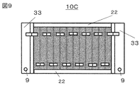
- the unit cell 1 is disposed in the direction in which the wide surface of the unit cell 1 is substantially perpendicular to the bottom surface of the case as shown in FIG. , 33) to obtain a battery group 10C.
- the housing and the battery group 10C were fixed using screws.
- the electrical component is disposed on the path connecting the unit cell 1 from the external terminal 9. From the electrode portion of the battery group 10C to the external terminals, electrical connections were made by connecting the same electrical components as in Example 1 using bus bars and cables. In this comparative example, the same current application conditions as in Example 1 and a surrounding cooling environment were given to the battery of the above configuration, and the result when the battery is in a substantially steady state is shown in FIG.
- Comparative example 2 The battery configuration described in Patent Document 1 was simulated to be a comparative example. Specifically, a unit cell 1 formed by winding an electrode made of an Al current collector foil and a positive electrode material having a layered structure as a positive electrode, and an electrode made of a Cu current collector foil and a carbon material as a negative electrode In order to compare only the battery group 10D with the first embodiment, a group consisting of six single batteries is used as in the first embodiment. The battery groups 10D were disposed in such a manner that the side surfaces of the battery groups 10D were in physical contact with each other.
- a single electrode is formed by using an electrode made of an Al current collector foil and a positive electrode material having a layered structure as a positive electrode, and an electrode made of an Al current collector foil and a spinel oxide as a negative electrode.
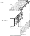
- Six batteries were stacked as described in FIG. 10, and the periphery thereof was fixed using a fixing pressing jig to obtain a battery group 10D.
- the same current application conditions as in Example 1 and the surrounding cooling environment are given to the battery of the above configuration, and the result when the battery is in a substantially steady state is shown in FIG.
- Comparative Example 1 cell numbers are assigned in order from the left cell shown in FIG.
- the unit cells having the same positional relationship of height from the bottom were substantially the same temperature in the stacked battery groups, and therefore, only six unit cells having different heights were described.
- the height from the bottom of the case is higher in the order of smaller cell numbers in the figure.
- Example 1 which is an example to which the present invention is applied together with Comparative Examples 1 and 2 is shown in FIG. From the figure, in Comparative Example 1, the cell No. 1 which is the central portion in which the batteries are stacked. It can be seen that the temperatures of 6 and 7 are maximum. This is cell number. In the battery near 7, the heat generated by the surrounding batteries is not dissipated, so that not only its own battery temperature but also the surrounding battery temperature is high, and heat does not flow easily because no temperature difference exists, as a result This is because the battery temperature is high.
- Example 1 and Comparative Example 2 as shown in FIG. 11, the number of stacked battery groups decreases, and the temperature rise ratio of the six battery groups is 12 in a comparative example. It turns out that it is decreasing compared with 1. Due to this influence, in Comparative Example 2, it is considered that the temperature rise is suppressed as compared with Comparative Example 1.
- the surfaces on which the external terminals of the battery groups are arranged are opposed to each other in the housing, and the battery groups are not physically and thermally connected. As a result, the thermal resistance is reduced more than in Comparative Example 2, and it is considered that the temperature of the unit cell is also reduced as compared with Comparative Example 2.
- an electrode formed of an Al current collector foil and a positive electrode material having a layered structure as a positive electrode, and an electrode formed of an Al current collector foil and a spinel oxide as a negative electrode, are single electrodes formed by winding those electrodes.
- the case where it compares with the structure in this invention, and the structure in a well-known example is shown using six batteries.
- the results in FIG. 12 indicate that the effects of the present invention can be obtained even when the battery type is changed.
- the third embodiment differs from the first embodiment in that a water cooling jacket 107 is provided on the side surface of the housing 7.
- the same reference numerals as in the first embodiment denote the same parts as in the first embodiment.
- FIG. 6 shows the structure of the third embodiment.
- a water cooling jacket 107 is provided on the side surface of the housing 7 as shown in FIG. Therefore, in addition to the effects of the first embodiment, the cooling performance can be further enhanced.
- the fourth embodiment differs from the first embodiment in that an air-cooling fin 177 is provided on the side surface of the housing 7.
- the same reference numerals as in the first embodiment denote the same parts as in the first embodiment.
- FIG. 7 shows the structure of the fourth embodiment.
- fins 177 for air cooling are provided on the side surface of the housing 7. Therefore, in addition to the effects of the first embodiment, the cooling performance can be further enhanced.
- the air cooling system is used in this embodiment, the cooling performance is reduced as compared with the third embodiment, but an apparatus and the like necessary for water cooling become unnecessary, and the system can be made compact when mounted on a vehicle.
- the fifth embodiment differs from the first embodiment in that the pressure binding member 2 is also used as the housing 277.
- the same reference numerals as in the first embodiment denote the same parts as in the first embodiment.
- FIG. 8 shows the structure of the fifth embodiment.
- the side surface of the housing 277 is in direct contact with the battery groups 10A and 10B, and the pressure binding jig 3 is connected to the housing 277. .
- the pressure binding member 3 is directly connected to the housing 277. Further, in the present embodiment, in order to increase the contact area between the pressure binding jig 3 and the housing 277, housing side surface concave portions 277A and 277B for housing the pressure binding jig 3 and two housing side surface concave portions A casing side convex portion 277C is provided between the 277A and 277B. With such a structure, the side surfaces of the battery groups 10A and 10B directly contact the housing 277 without the pressure binding jig, so that the cooling performance is improved.
- the pressing binding jigs 3 of the battery groups 10A and 10B are arranged in the casing side surface concave portions 277A and 277B, the contact area of the pressing binding jig 3 with the casing 277 is increased, and the pressing restraint jigs 3 are increased. Heat dissipation from the tool 3 is promoted. Furthermore, since the two pressure binding jigs 3 are also in contact with the case side convex portion 277C, the heat radiation from the pressure binding jigs 3 is further promoted.
- a battery cell comprising a pair of wide side surfaces, a pair of narrow side surfaces, a bottom surface connecting the wide side surfaces and the narrow side surfaces, and an upper surface on which external terminals are arranged
- the surface on which the terminals (12, 13) are disposed and the surface on which the external terminals (12, 13) of the second battery group (10B) are disposed are opposed to each other.
- the four surfaces of the battery groups 10A and 10B that is, the two side surfaces of the battery groups 10A and 10B (the surface on which the pressure binding jig 2 is disposed), the bottom surface of the unit cell 1 Since the lowermost surface of the battery groups 10A and 10B (the surface on which the lower pressure binding jig 3 is disposed) can be used directly for cooling by directly contacting the housing 7, the cooling performance is improved. .
- the space for earning the creeping distance of the battery groups 10A and 10B can be used as a storage space for electrical components, and the battery pack 100 can be prevented from being enlarged.
- the battery pack (100) according to the present invention, as an electrical component, at least two or more of the substrate (20), the relay (23), or the fuse (22), two or more parts. As one assembly can be made, the effect of improvement in workability can be obtained.
- the battery pack (100) according to the present invention is characterized in that the electrical components are respectively integrated in the insulating member. With such a structure, while securing insulation between the battery groups 10A and 10B, it is not necessary to arrange the electrical components in the narrow space between the battery group 10A and the battery group 10B. Therefore, since the support stand 4 to which the electrical component is fixed can be collectively fixed to the housing 7 etc., the workability can be improved while securing the insulation between the battery groups 10A and 10B.
- the electrical components are the substrate (20), the relay, the (23) and the fuse (23), and one side of the insulating member is the substrate (20), the other side A relay (23) and a fuse (22) are disposed in the.
- the flat member BMS 20 can be disposed on one side, which is a waste as compared to a structure in which the relay 23 is disposed on one side of the support 4 and the fuse 22 is disposed on the other side. Uneven space does not occur. Therefore, it contributes to miniaturization.
- the present invention is not limited to the above-mentioned embodiment, and various designs are possible in the range which does not deviate from the spirit of the present invention described in the claim. It is possible to make changes.
- the above-described embodiment has been described in detail in order to explain the present invention in an easy-to-understand manner, and is not necessarily limited to one having all the described configurations.
- part of the configuration of one embodiment can be replaced with the configuration of another embodiment, and the configuration of another embodiment can be added to the configuration of one embodiment.
Landscapes
- Chemical & Material Sciences (AREA)
- Chemical Kinetics & Catalysis (AREA)
- Electrochemistry (AREA)
- General Chemical & Material Sciences (AREA)
- Battery Mounting, Suspending (AREA)
- Secondary Cells (AREA)
- Connection Of Batteries Or Terminals (AREA)
Abstract
本発明によれば、電池群同士の外部端子が配置された面同士を互いに筐体内で対向させ、電池群同士を熱的に物理的に接続させない構造とすることで、電池群の熱抵抗を低減させ、これにより電池群内にある単電池の温度を低減することを課題とする。 本発明に記載の電池パックは、一対の幅広側面と、一対の幅狭側面と、前記幅広側面及び幅狭側面とを接続する底面と、外部端子が配置された上面と、を備えた電池セルを有し、前記電池セルの幅広側面を対向させて、複数個積層した第一の電池群と、前記電池セルの幅広側面を対向させて、複数個積層した第二の電池群と、前記第一の電池群及び第二の電池群を収納する筐体と、を備え、前記第一の電池群の外部端子が配置された面と、前記第二の電池群の外部端子が配置された面とは互いに対向して配置される。
Description
本発明は、電池パックに関する。
環境問題・資源枯渇問題を背景にして、地球環境の保全に向けた、環境負荷の低い省エネルギーな製品の開発が求められている。CO2量の削減につながる製品のひとつとして、ハイブリッド電気自動車や電気自動車に代表されるエコカーに注目が集まっており、その販売台数が伸びている。これらのエコカーに搭載される車載用の二次電池への需要も高まっている。車載用二次電池の例としては、リチウムイオン二次電池や、鉛蓄電池、ニッケル水素電池などが挙げられる。この中で、リチウムイオン二次電池は一般に、鉛電池やニッケル水素電池などに比べて放電電位が高いため、小型・高エネルギー密度化が可能であり、有望視されている。
本格適用に向けてリチウムイオン二次電池に求められる点には例えば、更なる高エネルギー密度化、高出力密度化、長寿命化等があげられる。電池を高出力化するためには高電位化とともに、例えば、大電流を電池から入・出力させる事が有効である。しかし大電流を電池から入・出力させる場合、電池の内部抵抗に由来する発熱が電池内部で生じる。発生した熱を十分に電池から取り除く事ができなかった場合、電池温度が上昇する。リチウムイオン電池の電池容量や内部抵抗等の電池特性は、電池温度によって劣化傾向が異なり、特に電池温度が高ければ高いほど電池劣化が進み、容量低下や内部抵抗上昇が起こる場合が多い。そこで、電池の放熱性能を向上させる技術開発が必要となっている。
複数のリチウムイオン単電池(以下、単電池と呼ぶ)が組み合わされ、電池群として用いられる場合(例えば、電池モジュール、電池パックとして使用する場合)、電池群中の単電池間の温度差を小さく、さらに電池群の中に存在する電池の最大到達温度が低いことが望まれる。これは、単電池間での温度差が大きく、さらに最大到達温度が高いい場合、単電池間で劣化の差が生じやすいためである。電池群の特性は、電池群に含まれる単電池の中で、最も劣化した電池の特性に律速される傾向があるため、特定の電池が劣化しない電池群の設計が必要となる。
そこで、複数の単電池が組み合わされて形成された電池群において、様々な電池配置の構成が開発されている。例えば特許文献1には、単電池の幅広面に略垂直な方向に5つの単電池が積層されてなる電池群が、筐体の底面を構成する板上に2つ並べて配置された構成が記載されている。一般に、直列に接続された電池には同じ電流値が印加されるため、内部抵抗がほぼ同じ電池であれば電池の温度は同等程度になる。この場合、電池間の熱流が生じにくいために電池の積層数が多ければ多いほど、積層された電池群の中心部分の温度が断熱状態に近づき、電池群の端部に比べて高温になる事が知られている。特許文献1のように直列にした電池群を二列に分けた場合、電池群は筐体底面から見て電池が5個積層されたのと同じ構成となるため、電池群の内の中心部分の電池の温度が低下しやすいメリットがある。加えて、直列電池群を分けるため、低背化が可能であるという特徴がある。
特許文献1に記載される構造の様に、電池群同士の側面を熱的に物理的に接続して配置した場合、電池群の接続面から熱が逃げる経路としては、電池群間に挟まれた部材を経由し、その部材の正面にある筐体を介して放熱する必要があり、放熱経路が冗長化する問題があった。放熱経路が冗長化した場合、熱抵抗は高くなる傾向があり、放熱性を向上させるためには改良の余地がある。
このような構成では、冷却効率が低下した場合(例えば強制流通させる空気の流量が小さい場合や、入出力電流が大きく単電池の発熱量が大きい場合)、構成される電池群内の
電池温度に分布が生じ、特に電池群中に積層された電池群のうち、中心付近に配置された単電池の電池温度が高く、劣化が進む恐れがある。本発明は、前記課題に鑑みてなされたものであり、電池群間の温度差が小さい電池パックを提供する事を課題とする。
電池温度に分布が生じ、特に電池群中に積層された電池群のうち、中心付近に配置された単電池の電池温度が高く、劣化が進む恐れがある。本発明は、前記課題に鑑みてなされたものであり、電池群間の温度差が小さい電池パックを提供する事を課題とする。
本発明に記載の電池パックは、一対の幅広側面と、一対の幅狭側面と、前記幅広側面及び幅狭側面とを接続する底面と、外部端子が配置された上面と、を備えた電池セルを有し、前記電池セルの幅広側面を対向させて、複数個積層した第一の電池群と、前記電池セルの幅広側面を対向させて、複数個積層した第二の電池群と、前記第一の電池群及び第二の電池群を収納する筐体と、を備え、前記第一の電池群の外部端子が配置された面と、前記第二の電池群の外部端子が配置された面とは互いに対向して配置される。
本発明によれば、電池群同士の外部端子が配置された面同士を互いに筐体内で対向させ、電池群同士を熱的に物理的に接続させない構造とすることで、電池群の熱抵抗を低減させ、これにより電池群内にある単電池の温度を低減する事ができる。
本発明を実施するための形態について説明する。ただし、本実施形態は以下の内容に何ら制限されるものではなく、本発明の要旨を逸脱しない範囲内で任意に変更して実施可能である。また本発明における冷却環境は例示であり、空気や水以外のその他の冷媒を用いた場合にも適用できる。
本発明における二次電池には、リチウムイオン二次電池を例示したが、本構成を他の種類の蓄電池に対しても適用できる。またリチウムイオン二次電池の構成部材はどのようなものであっても効果が得られる。つまり本発明では正極としてAl集電箔と層状構造を持つ正極材などからなる電極と、負極としてCu集電箔と炭素材料からなる電極を用いているが、その他の構成でも良い。例えば負極の集電箔にAl箔を用いた場合においても放熱性を向上することが可能である。またリチウムイオン電池の形状として本実施例では角形電池を用いたが、その他の形状として知られる例えばラミネート型、円筒型等電池であっても効果が得られる。
筐体中に含まれる電池群の数は、本発明における構成であるように、電池の側面が筐体の側面に物理的に熱的に接触することで、電池群の側面からの放熱経路が短縮できる限り、いくつであっても良いが、好ましくは電池パックの安定性を確保するために偶数がよい。例えば、本発明の実施例のように電池群を2個とした場合、筐体の左右両側の側面に電池群を物理的に熱的に接触させて配置することができる。
また、電池群を構成する電池数は、本発明における構成とすることができ、筐体内に収まり、所望の電圧や容量を確保できる限りは、何本としても、本発明における効果が得られる。放熱効果としては、ひとつの電池群中の単電池の積層本数は少なければ少ないほど効果が現れるが、好ましくは100本以下、より好ましくは20本以下、最も好ましくは10本以下である。本発明の実施例のように6本とすることで小型かつ冷却性を兼ね備えた電池パックとすることができる。
さらに、対向させる電池群同士の電池数は必ずしも同じでなくても本発明における効果を得る事ができる。例えば電池群のうちの一方の電池数が、他方の電池数に比べて一本以上多い場合も、本発明における効果を得ることができる。
また電池群をなす単電池の間に、例えば絶縁性シートや熱伝導性の高い部材を配置しても本発明の効果は得られるし、配置しなくても本発明の効果は得られる。また絶縁性のシートや熱伝導性の高い部材には例えばレール状、点状、など種々の形状の突起や溝などの立体構造を導入しても本発明における効果が得られる。単電池の側面が絶縁材料で被覆されている場合、これらの部材の材料として、アルミニウム、アルミダイカスト、銅、鉄等の熱伝導性の高い材料を用いることができる。また、単電池の側面が、絶縁材料で被覆されていない場合はポリプロピレン、ポリアミド、ポリエーテルイミド、PPS、PPA、PBT等あるいは高熱伝導性樹脂を用いることができる。
本発明では、電池群同士を筐体内部の対面同士に配置し、電極面が向き合う形となるため、対向させる電池群同士の間には、圧壊安全性を確保するため、電池群間に絶縁性の部材を少なくとも一部配置する事が好ましい。部材の例としては例えば以下が挙げられる。
絶縁部材を、構成部材の一部に少なくとも用いられて作成される支持台であり、前記支持台には電池の安全機構(例えばヒューズなど)や、制御装置(例えば、Battery Management System:BMSなどがあげられる)や、プリチャージに必要なリレー、シャント抵抗、バスバーや導線などの導電性の配線、などの電装品の内、少なくとも一つを備えても良い。加えて、前記支持台は、これらの電装品を固定できる螺子や螺子穴や固定器具を備えても良い。これらの固定器具を用いて前記した電装品を支持台と一体化することで、導電性の配線を介して安全機構などの電装品と電池群をつなぎ、外部端子まで電気的に接続することができる。これにより、電池群それぞれの端子面の間に絶縁性の部材を導入可能であるため、圧壊安全性を備えつつ、放熱性も高い電池パックとすることができる。
またこれらの支持台へ、安全機構などを取り付ける方法や位置関係は、本発明は特に限定されない。例えば絶縁性の支持台の上・下面や側面、内部にこれらの機器が配置・内蔵されていても良い。またこれらの機器の電気的な配置の順番にも特に制限されない。また支持台の大きさや形状も、電池群同士が圧壊により接近した場合に二つの電池群の絶縁性が確保できれば、どの様な大きさや形状でも良い。例えば、支持台が薄板状でも良いし、本発明に例示した支持台のように、各電装品を格納するために複雑な三次元形状としても良い。
本発明の様に電池群が配置されれば、電池群を構成する単電池同士を電気的にどの様に接続しても本発明における効果を得る事ができる。例えば、電池群同士に対して配線を工夫することで並列に接続しても本発明における効果を得る事ができる。ここでは例として、電池群同士内の単電池を直列接続し、更に対向する二つの電池群同士も直列接続する場合の例を説明する。
電池群同士を対向させた後に電池群を直列に接続する方法には、例えば以下が挙げられる。
(A)電池群同士を、バスバーを用いて直接接続する方法。この際、バスバー同士は作業性を考慮して、接続のために伸ばしたバスバーや配線の一部を使用して、ネジや溶接などの手法を用いて電気的に接続してもよい。ただし電気的に接続する方法はこれらのみには限らない。
(B)前記した、絶縁性の部材を構成部材に含む支持台を経由してバスバー同士を電気的に接続する方法。この際、支持台にはバスバー或いはケーブルなどの導電部を内蔵し、それらの導電性部材を介して電気的に接続する事が好ましい。
(C)ケーブルを用いて電池群同士を直接接続する方法。
(D)前記した、絶縁性の部材を構成部材に含む支持台を経由してケーブル同士を電気的に接続する方法などが挙げられる。
また電池群は、単電池同士を電気的に直列あるいは並列接続することに加え、固定用の治具を用いて単電池同士を物理的に拘束することが好ましい。固定用の治具の材料には、単電池の側面が絶縁材料で被覆されている場合、アルミニウム、アルミダイカスト、銅、鉄等の熱伝導性の高い材料を用いることができる。また、単電池の側面が、絶縁材料で被覆されていない場合はポリプロピレン、ポリアミド、ポリエーテルイミド、PPS、PPA、PBT等あるいは高熱伝導性樹脂を用いることができる。また、拘束の方法には本発明は限定されない。例えば、二つの電池群を固定用の治具一セットを用いて束縛した場合でも、固定用の治具2セットを用いて固定した場合でも効果が表れた。また固定用の治具の少なくとも一部が筐体であっても本発明における効果が得られた。
筐体と電池群および支持台などの各部材の接触方法は特に限定されず、例えば接着剤などによる接着や、ボルトやナットなどの固定器具を介しての接続でも本発明における効果はあらわれる。筐体の形状は本実施形態においては直方体を例示するが、その形状は特に限定されない。また本発明における効果は電池パックへの電流印加条件や冷却条件に限定されない。
本発明で例示する支持台には、熱伝導性の良いバスバーや導線が配置されるため、支持台から熱を逃がす機構を設けた場合、冷却効果が期待できる。例えば、支持台と熱的に接触する部分にヒートパイプや冷却管などの冷却機構を設けても良い。
また、筐体にフィンやその他の冷媒を用いたジャケットや配管などの冷却機構を設けても、本発明における構造をとることで効果が得られる。
筐体の種類には例えば、樹脂製筐体や、金属製筐体などが挙げられるが、特に制限されない。好ましくはアルミニウム、アルミダイカスト、銅、鉄等の熱伝導性金属製の筐体である事が好ましい。
蓋から現れる外部端子の位置は本発明の例示では電装品配置可能スペースの上部に配置したが、外部端子の位置を加圧用束縛治具の上部に配置する事もできる。この場合も本発明における構造をとることで本発明における効果が得られる。実施例では、絶縁性の部材を構成部材に含む支持台に対して、バスバー等の導線が配置されており、それに対してネジを用いて各種電装品を接続することで、電気的に接続する方法が例示されている。
(実施例1)
以下、実施例及び比較例に基づいて、本発明をさらに詳細に説明する。
以下、実施例及び比較例に基づいて、本発明をさらに詳細に説明する。
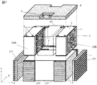
まず図3を用いて本発明にかかる電池パック100の概要を説明する。図3は本発明の電池パック100の分解斜視図である。本発明に係る電池パック100は、2つの電池群10A、10B、当該2つの電池群10A、10Bを収納する金属製の筐体7、筐体7の開口を塞ぐ蓋8、図3では図示されていない電装品を配置した支持台4から構成されている。なお、支持台4は電池群10Aと電池群10Bの間の電装品配置スペース4Aに配置される。電池群10A、10Bは互いに単電池1の端子(正極端子12、負極端子13)を対向させるように配置されており、互いに配線6で電気的に接続されている。蓋8には外部端子9が配置され配線6と電気的に接続されており、この外部端子9を介して電池パック100から電力が取り出されるようになっている。
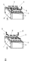
この電池群10A、10Bの詳細については図1を用いて説明する。単電池1には一対の幅広面、一対の幅狭面、底面、上面から構成されており、上面には正極端子12と負極端子13が配置されている。そして単電池1の間には絶縁性のスペーサ11が配置され、この端子の正負極が互い違いになるように単電池1が積層されている。
最上部に配置された単電池1の幅広面と、最下部に配置された単電池1の幅広面のそれぞれに対向して一対の加圧用束縛治具3が配置されている。
また、単電池1の幅狭側面に対向して一対の加圧用束縛治具2が配置されており、加圧用束縛治具2と加圧用束縛治具3とが互いに固定用金具5で固定されている。
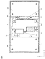
続いて図2に配線6と各単電池1との接続を示す。配線6は外部端子9と接続される配線6Aと、互いの単電池1間同士を接続する配線6C、電池群10A、10B間を接続する配線6Bの3つの種類に分けられる。これらの配線6A、6B、6Cが接続され電池群10A、電池群10Bが構成される。なお、電池群10Aの配線6Bと電池群10Bの配線6Bとは互いに接続される。
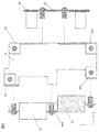
続いて図3の蓋8を外した状態で筐体7の開口側から見た図を図4に示す。第一の電池群10Aと第二の電池群10Bとの間に配置された支持台4は配線6Aと接続され、この配線6Aは蓋8に設けられた外部端子9と接続される支持台端子部6A1に電気的に接続される。この支持台4には、BMS(基板)20、シャント抵抗21、ヒューズ22、リレー23が組み付けられる。組み付け方については図5を用いて詳述する。なお、この支持台は絶縁部材が用いられ、例えば絶縁性の樹脂材が使用される。
続いて図5を用いて支持台4の説明をする。支持台4の一方の面にはBMS20とシャント抵抗21が配置され、他方の面にはヒューズ22とリレー23が配置される。BMS20とシャント抵抗21は一体に組み付けられた状態で、一方側が配線6Aに、他方側が支持台端子部6A1に接続される。
他方の面に配置されるヒューズ22とリレー23は大きな部品であるため、他方側の面には2つの凹部が設けられ、そこにヒューズ22とリレー23が収容される構造となっている。このような構造にすることによって支持台4と電装品の一体アッセンブリを小型にすることができる。なお、ヒューズ22とリレー23とは互いに接続配線6A2で接続して一体にしたのちに支持台4に組み付けてもよい。また、電装品を組み付ける際にはねじ等の部品で組み付けるが、組み付け方はそれに限定されるものではない。
続いて本実施形態の特徴部について再度図3に戻って説明する。
本実施形態では電池群10A、10Bの4つの面、つまり、電池群10A、10Bの2つの側面(加圧用束縛治具2が配置されている面)、単電池1の底面、電池群10A、10Bの最下面(下側の加圧用束縛治具3が配置されている面)が直接筐体と接するように筐体7に収納している。そのため、2つ以上の電池群10A、10Bを収納する際に最も冷却性が向上する。一方で、冷却効率を向上させるために電池群10Aの端子が配置されている面と電池群10Bの端子が配置されている面とが互いに対向されるように収納する必要がある。そのため、本発明では、電池パック100に必要な電装品を絶縁性の支持台に組み付けて電池群10Aと電池群10Bの間に配置するように構成した。そのため、電池パック100としての冷却性を向上させつつ、2つの電池群10Aと電池群10Bの絶縁性も確保でき、電池パック100の大型化を防ぐことができる。この電池パック100の大型化を防ぐことができるという点についてより詳細に説明する。もともと電池群10Aの端子側面と電池群10Bの端子側面を対向させようとすると二つの電池群のために沿面距離を稼ぐ必要があり、その分電池パック100として体積が増加する。そのため、電池群10A、10Bの沿面距離を稼ぐ分の空間を支持台を配置する空間に重ねることができるため、電池パック100の大型化を防ぐことができる。
本構造のさらなる効果としては、一旦支持台4に電装品を一体化してから電池パック100を構成することとしている。そのため、電池群10Aと電池群10Bとの間の狭い空間で電装品の配置作業をすることなく、電装品が固定された支持台4を筐体7等に一括で固定すれば作業が済むため電池パック100を作成する際の作業性が向上する。
また本実施例では、支持台4の一方側には基板(20)、他方側には大きな部品であるリレー(23)及びヒューズ(22)が配置されている。このような構造にすることによって、平面部材であるBMS20を一方側に配置することができ、支持台4の片側にリレー23、もう片側にヒューズ22を配置するといったような構造と比較して無駄な凹凸空間が発生しなくなる。そのため、小型化に寄与するようになる。
なお、本実施形態では配線6としてバスバーを用いたが、ケーブルを用いてもよい。
上記のようにして作製した電池パックに対して電流を印加した。この際、筐体の下面に熱伝導率の低い部材を配置して電流を印加し、略空気の流れの無い恒温槽中での試験結果とした。なお電池からの発熱量は電流値から計算して平均3Wとなるように電流値を印加した。本実施例では、前記条件を電池パックに与えた後、ほぼ定常状態となった際の温度挙動を図11に示す。
(実施例2)
本実施例では、正極としてAl集電箔と層状構造を持つ正極材などからなる電極と、負極としてAl集電箔とスピネル系酸化物からなる電極を用い、それらの電極を捲回してなる単電池6本を図1に記載するように積層させ、その周囲を固定用の加圧治具を用いて固定することで電池群を得た。本実施例は、前記構成の電池に対して、実施例1と同様の電流印加条件および周囲の冷却環境を与え、ほぼ定常状態となった際の結果を図12に示す。
本実施例では、正極としてAl集電箔と層状構造を持つ正極材などからなる電極と、負極としてAl集電箔とスピネル系酸化物からなる電極を用い、それらの電極を捲回してなる単電池6本を図1に記載するように積層させ、その周囲を固定用の加圧治具を用いて固定することで電池群を得た。本実施例は、前記構成の電池に対して、実施例1と同様の電流印加条件および周囲の冷却環境を与え、ほぼ定常状態となった際の結果を図12に示す。
(比較例1)
正極としてAl集電箔と層状構造を持つ正極材などからなる電極と、負極としてCu集電箔と炭素材料からなる電極を用い、それらの電極を捲回してなる単電池を用い、12個の単電池1を直列につなげることで単一の電池群10A、10Bとした。この際、単電池1間には実施例1と同様のスペーサ11を配置した。電池群を図9の様に筐体底面に対して、単電池1の幅広面が略垂直な方向に単電池1を配置し、これら12本の電池群を固定用の加圧治具(22、33)を用いて固定することで電池群10Cを得た。筐体と電池群10Cはネジを使用して固定した。なお、図9は、筐体の蓋面の上面から見た平面図である。本比較例では実施例1と同様に、外部端子9から単電池1を繋ぐ経路上に電装品を配置されることとなる。電池群10Cの電極部から外部端子までは、バスバーおよびケーブルを用いて実施例1と同じ電装品を接続することで電気的に接続した。本比較例は、前記構成の電池に対して、実施例1と同様の電流印加条件および周囲の冷却環境を与え、ほぼ定常状態となった際の結果を図11に示す。
正極としてAl集電箔と層状構造を持つ正極材などからなる電極と、負極としてCu集電箔と炭素材料からなる電極を用い、それらの電極を捲回してなる単電池を用い、12個の単電池1を直列につなげることで単一の電池群10A、10Bとした。この際、単電池1間には実施例1と同様のスペーサ11を配置した。電池群を図9の様に筐体底面に対して、単電池1の幅広面が略垂直な方向に単電池1を配置し、これら12本の電池群を固定用の加圧治具(22、33)を用いて固定することで電池群10Cを得た。筐体と電池群10Cはネジを使用して固定した。なお、図9は、筐体の蓋面の上面から見た平面図である。本比較例では実施例1と同様に、外部端子9から単電池1を繋ぐ経路上に電装品を配置されることとなる。電池群10Cの電極部から外部端子までは、バスバーおよびケーブルを用いて実施例1と同じ電装品を接続することで電気的に接続した。本比較例は、前記構成の電池に対して、実施例1と同様の電流印加条件および周囲の冷却環境を与え、ほぼ定常状態となった際の結果を図11に示す。
(比較例2)
特許文献1に記載されている電池構成を模擬し、比較例とした。具体的には、正極としてAl集電箔と層状構造を持つ正極材などからなる電極と、負極としてCu集電箔と炭素材料からなる電極を用い、それらの電極を捲回してなる単電池1を用い、電池群10Dのみを実施例1と比較できるよう、実施例1と同様に、6つの単電池からなる群とした。それらの電池群10Dの側面をそれぞれ物理的に接触させる形で電池群10Dを配置した。外部端子から電池群10Dの電極を繋ぐ経路上に電装品を配置されることとなり、電装品を電極部から外部端子までは、バスバーおよびケーブルを用いて実施例1と同じ電装品を接続することで電気的に接続した。また、実施例1と略同じ冷却環境を与えるため、前記電池群の周囲に筐体77および蓋88を新たに設けて比較実験とした。このような構成とした電池群10Dに対し、実施例1と同様の電流印加条件および周囲の冷却環境を与え、ほぼ定常状態となった際の結果を図11に示す。
特許文献1に記載されている電池構成を模擬し、比較例とした。具体的には、正極としてAl集電箔と層状構造を持つ正極材などからなる電極と、負極としてCu集電箔と炭素材料からなる電極を用い、それらの電極を捲回してなる単電池1を用い、電池群10Dのみを実施例1と比較できるよう、実施例1と同様に、6つの単電池からなる群とした。それらの電池群10Dの側面をそれぞれ物理的に接触させる形で電池群10Dを配置した。外部端子から電池群10Dの電極を繋ぐ経路上に電装品を配置されることとなり、電装品を電極部から外部端子までは、バスバーおよびケーブルを用いて実施例1と同じ電装品を接続することで電気的に接続した。また、実施例1と略同じ冷却環境を与えるため、前記電池群の周囲に筐体77および蓋88を新たに設けて比較実験とした。このような構成とした電池群10Dに対し、実施例1と同様の電流印加条件および周囲の冷却環境を与え、ほぼ定常状態となった際の結果を図11に示す。
(比較例3)
本比較例では、正極としてAl集電箔と層状構造を持つ正極材などからなる電極と、負極としてAl集電箔とスピネル系酸化物からなる電極を用い、それらの電極を捲回してなる単電池6本を図10に記載するように積層させ、その周囲を固定用の加圧治具を用いて固定することで電池群10Dを得た。本比較例は、前記構成の電池に対して、実施例1と同様の電流印加条件および周囲の冷却環境を与え、ほぼ定常状態となった際の結果を図12に示す。
本比較例では、正極としてAl集電箔と層状構造を持つ正極材などからなる電極と、負極としてAl集電箔とスピネル系酸化物からなる電極を用い、それらの電極を捲回してなる単電池6本を図10に記載するように積層させ、その周囲を固定用の加圧治具を用いて固定することで電池群10Dを得た。本比較例は、前記構成の電池に対して、実施例1と同様の電流印加条件および周囲の冷却環境を与え、ほぼ定常状態となった際の結果を図12に示す。
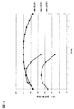
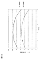
本実施例や比較例に示す条件を電池群に与えた結果、電池群の温度はほぼ定常状態に達した際に、環境温度に比べて電池温度が上昇した。図11及び図12では、本発明における実施例および比較例の中で、最も温度上昇が高くなった、比較例1中に存在する電池群の中で、環境温度からの温度上昇が最も大きかった電池の温度上昇を100%として、各例の中に存在する単電池の温度上昇比率を比較した。
比較例1については、図9に示す左の単電池から順にセルNoをつけている。一方で比較例1以外は、積層された電池群について、底面からの高さの位置関係が同じ単電池については略同じ温度となったため、高さの異なる単電池6本についてのみ記載した。一方で比較例1を除く例の中では、図中のセルNoが小さい順に筐体底面からの高さが高くなっている。
以下に各図の結果について詳細に説明する。
図11には比較例1、2とともに、本発明を適用した例である、実施例1の温度上昇比率を示す。図から比較例1では電池を積層させた中心部分であるセルNo.6および7の温度が最大となる事が分かる。これはセルNo.7付近の電池では、周囲の電池で発生した熱量が放熱されないため、自身の電池温度だけでなく周囲の電池温度も高くなっており、温度差がつかないために熱が流れにくくなり、結果として電池温度が高くなっているためである。
一方で、実施例1および比較例2では図11に示すように、積層された電池群の数が減少数することで6本の電池群の温度上昇比率が、12本積層されている比較例1に比べて減少している事が分かる。この影響があり、比較例2では、比較例1に比べて温度上昇が抑えられていると考える。それに加え、実施例1ではさらに、電池群同士の外部端子が配置された面同士を互いに筐体内で対向させ、電池群同士を熱的に物理的に接続させない構造としている。これにより比較例2よりも熱抵抗が低減され、比較例2に比べても単電池の温度を低減したと考える。
図12には、正極としてAl集電箔と層状構造を持つ正極材などからなる電極と、負極としてAl集電箔とスピネル系酸化物からなる電極を用い、それらの電極を捲回してなる単電池6本を用いて、本発明における構成と、公知例における構成で比較した場合を示す。図12の結果は、電池種を変えても本発明における効果があらわれることがわかる。
(実施例3)
続いて実施例3について説明する。実施例3が実施例1と異なる点は筐体7の側面に水冷ジャケット107が設けられている点である。なお、実施例1と同様の構成については同様の図面番号を付している。
続いて実施例3について説明する。実施例3が実施例1と異なる点は筐体7の側面に水冷ジャケット107が設けられている点である。なお、実施例1と同様の構成については同様の図面番号を付している。
図6は実施例3の構造を示すものである。本実施例では図6に示すように筐体7の側面に水冷ジャケット107を設けた。そのため、実施例1の効果に加えて、さらに冷却性能を強化することができる。
(実施例4)
続いて実施例4について説明する。実施例4が実施例1と異なる点は筐体7の側面に空冷用のフィン177が設けられている点である。なお、実施例1と同様の構成については同様の図面番号を付している。
図7は実施例4の構造を示すものである。本実施例では図7に示すように筐体7の側面に空冷用のフィン177を設けた。そのため、実施例1の効果に加えて、さらに冷却性能を強化することができる。また、本実施例では空冷方式となるので、実施例3と比較して冷却性能は低下するが水冷に必要な装置等が不要となり、車両に搭載するときにコンパクトにすることができる。
続いて実施例4について説明する。実施例4が実施例1と異なる点は筐体7の側面に空冷用のフィン177が設けられている点である。なお、実施例1と同様の構成については同様の図面番号を付している。
図7は実施例4の構造を示すものである。本実施例では図7に示すように筐体7の側面に空冷用のフィン177を設けた。そのため、実施例1の効果に加えて、さらに冷却性能を強化することができる。また、本実施例では空冷方式となるので、実施例3と比較して冷却性能は低下するが水冷に必要な装置等が不要となり、車両に搭載するときにコンパクトにすることができる。
(実施例5)
続いて実施例5について説明する。実施例5が実施例1と異なる点は加圧用束縛部材2を筐体277と兼用した点である。なお、実施例1と同様の構成については同様の図面番号を付している。
続いて実施例5について説明する。実施例5が実施例1と異なる点は加圧用束縛部材2を筐体277と兼用した点である。なお、実施例1と同様の構成については同様の図面番号を付している。
図8は実施例5の構造を示すものである。本実施例では図8に示すように筐体277の側面が直接電池群10A、10Bと接触するようになっており、加圧用束縛治具3が筐体277に接続される構造となっている。
図8に示すように本実施例では加圧用束縛部材3が筐体277に直接接続される構造となっている。また、加圧用束縛治具3と筐体277との接触面積を増やすために本実施例では加圧用束縛治具3を収容するための筐体側面凹部277A、277Bと、2つの筐体側面凹部277A、277Bの間に配置される筐体側面凸部277Cが設けられている。このような構造にすることによって、電池群10A、10Bの側面部が加圧用束縛治具を介さずに直接筐体277に接触するため、冷却性能が向上する。また、電池群10A、10Bの加圧用束縛治具3が筐体側面凹部277A、277Bに配置されることによって、加圧用束縛治具3が筐体277との接触面積が増え、加圧用束縛治具3からの放熱が促進される。さらに2つの加圧用束縛治具3が筐体側面凸部277Cにも接触されるため、より加圧用束縛治具3からの放熱が促進される。
以上、簡単に本発明についてまとめる。
本発明の電池パック100では、一対の幅広側面と、一対の幅狭側面と、前記幅広側面及び幅狭側面とを接続する底面と、外部端子が配置された上面と、を備えた電池セル(1)を有し、電池セル(1)の幅広側面を対向させて、複数個積層した第一の電池群(10A)と、電池セル(1)の幅広側面を対向させて、複数個積層した第二の電池群(10B)と、第一の電池群(10A)及び第二の電池群(10B)を収納する筐体(7)と、を備え、第一の電池群(10A)の外部端子(12、13)が配置された面と、前記第二の電池群(10B)の外部端子(12、13)が配置された面とは互いに対向して配置される。このような構造にすることによって、電池群10A、10Bの4つの面、つまり、電池群10A、10Bの2つの側面(加圧用束縛治具2が配置されている面)、単電池1の底面、電池群10A、10Bの最下面(下側の加圧用束縛治具3が配置されている面)を直接筐体7と接するようにして冷却に使用できるようになるため、冷却性能が向上する。
また、本発明に記載の電池パック(100)は、第一の電池群(10A)の外部端子(12、13)が配置された面と、第二の電池群(10B)の外部端子(12、13)が配置された面の間の空間には、電装品が配置される。このような構造にすることによって、電池群10A、10Bの沿面距離を稼ぐ分の空間を電装品の収納空間とすることができ、電池パック100の大型化を防ぐことができる。
また、本発明に記載の電池パック(100)は、電装品として、基板(20)、リレー(23)、又はヒューズ(22)のうちの少なくとも2つ以上であれば、2つ以上の部品を一つのアッセンブリにできるため作業性向上の効果が得られる。
また、本発明に記載の電池パック(100)は、電装品が、それぞれ絶縁部材に一体化されていることを特徴とする電池パック。このような構造にすることによって電池群10A、10B間の絶縁性を確保しつつ、電池群10Aと電池群10Bとの間の狭い空間で電装品の配置作業をすることなくなる。そのため、電装品が固定された支持台4を筐体7等に一括で固定できるため電池群10A、10B間の絶縁性を確保しつつ、作業性も向上させることができる。
また、本発明に記載の電池パック(100)は、電装品が、基板(20)、リレー、(23)及びヒューズ(23)であり、絶縁部材の一方側には基板(20)、他方側にはリレー(23)及びヒューズ(22)が配置されている。このような構造にすることによって、平面部材であるBMS20を一方側に配置することができ、支持台4の片側にリレー23、もう片側にヒューズ22を配置するといったような構造と比較して無駄な凹凸空間が発生しなくなる。そのため、小型化に寄与するようになる。
以上、本発明の実施形態について詳述したが、本発明は、前記の実施形態に限定されるものではなく、特許請求の範囲に記載された本発明の精神を逸脱しない範囲で、種々の設計変更を行うことができるものである。例えば、前記した実施の形態は本発明を分かりやすく説明するために詳細に説明したものであり、必ずしも説明した全ての構成を備えるものに限定されるものではない。また、ある実施形態の構成の一部を他の実施形態の構成に置き換えることが可能であり、また、ある実施形態の構成に他の実施形態の構成を加えることも可能である。さらに、各実施形態の構成の一部について、他の構成の追加・削除・置換をすることが可能である。
1 単電池
2 加圧用束縛治具
3 加圧用束縛治具
4 支持台
5 固定用金具
6 配線
7 筐体
8 蓋
9 端子
10A、10B 電池群
2 加圧用束縛治具
3 加圧用束縛治具
4 支持台
5 固定用金具
6 配線
7 筐体
8 蓋
9 端子
10A、10B 電池群
Claims (5)
- 一対の幅広側面と、一対の幅狭側面と、前記幅広側面及び幅狭側面とを接続する底面と、外部端子が配置された上面と、を備えた電池セルを有する電池パックにおいて、
前記電池セルの幅広側面を対向させて、複数個積層した第一の電池群と、
前記電池セルの幅広側面を対向させて、複数個積層した第二の電池群と、
前記第一の電池群及び第二の電池群を収納する筐体と、を備え、
前記第一の電池群の外部端子が配置された面と、前記第二の電池群の外部端子が配置された面とは互いに対向して配置されることを特徴する電池パック。 - 請求項1に記載の電池パックにおいて、
前記第一の電池群の外部端子が配置された面と、前記第二の電池群の外部端子が配置された面の間の空間には、電装品が配置されることを特徴とする電池パック。 - 請求項2に記載の電池パックにおいて、
前記電装品は、基板、リレー、又はヒューズのうちの少なくとも2つ以上であることを特徴とする電池パック。 - 請求項3に記載の電池パックにおいて、
前記電装品は、それぞれ絶縁部材に一体化されていることを特徴とする電池パック。 - 請求項4に記載の電池パックにおいて、
前記電装品は、基板、リレー、及びヒューズであり、
前記絶縁部材の一方側には基板、他方側にはリレー及びヒューズが配置されることを特徴とする電池パック。
Applications Claiming Priority (2)
| Application Number | Priority Date | Filing Date | Title |
|---|---|---|---|
| JP2017-128212 | 2017-06-30 | ||
| JP2017128212A JP7099807B2 (ja) | 2017-06-30 | 2017-06-30 | 電池パック |
Publications (1)
| Publication Number | Publication Date |
|---|---|
| WO2019004069A1 true WO2019004069A1 (ja) | 2019-01-03 |
Family
ID=64742132
Family Applications (1)
| Application Number | Title | Priority Date | Filing Date |
|---|---|---|---|
| PCT/JP2018/023752 Ceased WO2019004069A1 (ja) | 2017-06-30 | 2018-06-22 | 電池パック |
Country Status (2)
| Country | Link |
|---|---|
| JP (3) | JP7099807B2 (ja) |
| WO (1) | WO2019004069A1 (ja) |
Families Citing this family (2)
| Publication number | Priority date | Publication date | Assignee | Title |
|---|---|---|---|---|
| JP7631857B2 (ja) * | 2021-02-09 | 2025-02-19 | 日産自動車株式会社 | 電池冷却システム |
| JP2024049847A (ja) * | 2022-09-29 | 2024-04-10 | 東芝ライテック株式会社 | 電池装置 |
Citations (6)
| Publication number | Priority date | Publication date | Assignee | Title |
|---|---|---|---|---|
| JP2008198525A (ja) * | 2007-02-14 | 2008-08-28 | Yazaki Corp | 電源装置 |
| JP2009004323A (ja) * | 2007-06-25 | 2009-01-08 | Yazaki Corp | 電源装置 |
| JP2011054353A (ja) * | 2009-08-31 | 2011-03-17 | Toshiba Corp | 二次電池装置、二次電池装置の製造方法、および二次電池装置を備えたフォークリフト |
| WO2015178456A1 (ja) * | 2014-05-22 | 2015-11-26 | 株式会社東芝 | 電池パックおよび電池装置 |
| US20160315298A1 (en) * | 2015-04-23 | 2016-10-27 | Ford Global Technologies, Llc | Traction Battery Assembly |
| WO2016204140A1 (ja) * | 2015-06-15 | 2016-12-22 | 株式会社オートネットワーク技術研究所 | 蓄電モジュール |
Family Cites Families (14)
| Publication number | Priority date | Publication date | Assignee | Title |
|---|---|---|---|---|
| JP2002134083A (ja) | 2000-10-25 | 2002-05-10 | Toyota Motor Corp | 集合電池パック |
| KR100612305B1 (ko) | 2004-06-25 | 2006-08-11 | 삼성에스디아이 주식회사 | 전지 모듈 |
| JP2009087720A (ja) * | 2007-09-28 | 2009-04-23 | Toshiba Corp | 電池パック |
| JP2009238643A (ja) * | 2008-03-27 | 2009-10-15 | Sanyo Electric Co Ltd | 車両用の電池ブロック |
| JP5343048B2 (ja) * | 2010-07-29 | 2013-11-13 | 日立ビークルエナジー株式会社 | 蓄電モジュールおよび蓄電装置 |
| WO2013140800A1 (ja) * | 2012-03-21 | 2013-09-26 | 株式会社リチウムエナジージャパン | 電源装置及び位置決めトレイ |
| JP5532357B2 (ja) * | 2012-08-10 | 2014-06-25 | 株式会社オートネットワーク技術研究所 | 電池用配線モジュール |
| JP2014063598A (ja) | 2012-09-03 | 2014-04-10 | Nec Energy Devices Ltd | 電池パック |
| DE102012217600A1 (de) * | 2012-09-27 | 2014-03-27 | Robert Bosch Gmbh | Batterie sowie Kraftfahrzeug mit Batterie |
| JP6136407B2 (ja) * | 2013-03-15 | 2017-05-31 | 株式会社Gsユアサ | 電源モジュール |
| JP6759534B2 (ja) * | 2014-09-04 | 2020-09-23 | 株式会社Gsユアサ | 蓄電装置 |
| JP6265088B2 (ja) * | 2014-09-04 | 2018-01-24 | 株式会社Gsユアサ | 蓄電装置 |
| JP2017004926A (ja) | 2015-06-15 | 2017-01-05 | 株式会社オートネットワーク技術研究所 | 蓄電モジュール、及び車載蓄電モジュール |
| JP6856423B2 (ja) * | 2017-03-29 | 2021-04-07 | ビークルエナジージャパン株式会社 | 電池パック |
-
2017
- 2017-06-30 JP JP2017128212A patent/JP7099807B2/ja active Active
-
2018
- 2018-06-22 WO PCT/JP2018/023752 patent/WO2019004069A1/ja not_active Ceased
-
2022
- 2022-04-27 JP JP2022073622A patent/JP7607612B2/ja active Active
-
2024
- 2024-09-04 JP JP2024152532A patent/JP2024167396A/ja active Pending
Patent Citations (6)
| Publication number | Priority date | Publication date | Assignee | Title |
|---|---|---|---|---|
| JP2008198525A (ja) * | 2007-02-14 | 2008-08-28 | Yazaki Corp | 電源装置 |
| JP2009004323A (ja) * | 2007-06-25 | 2009-01-08 | Yazaki Corp | 電源装置 |
| JP2011054353A (ja) * | 2009-08-31 | 2011-03-17 | Toshiba Corp | 二次電池装置、二次電池装置の製造方法、および二次電池装置を備えたフォークリフト |
| WO2015178456A1 (ja) * | 2014-05-22 | 2015-11-26 | 株式会社東芝 | 電池パックおよび電池装置 |
| US20160315298A1 (en) * | 2015-04-23 | 2016-10-27 | Ford Global Technologies, Llc | Traction Battery Assembly |
| WO2016204140A1 (ja) * | 2015-06-15 | 2016-12-22 | 株式会社オートネットワーク技術研究所 | 蓄電モジュール |
Also Published As
| Publication number | Publication date |
|---|---|
| JP7607612B2 (ja) | 2024-12-27 |
| JP7099807B2 (ja) | 2022-07-12 |
| JP2024167396A (ja) | 2024-12-03 |
| JP2019012619A (ja) | 2019-01-24 |
| JP2022115909A (ja) | 2022-08-09 |
Similar Documents
| Publication | Publication Date | Title |
|---|---|---|
| JP5037537B2 (ja) | 電気的接続部材、バッテリーモジュール及びバッテリーシステム | |
| CN202339948U (zh) | 电池组 | |
| CN102379058B (zh) | 电压感测部件和采用该电压感测部件的电池模块 | |
| KR102301195B1 (ko) | 배터리 팩 | |
| KR101252944B1 (ko) | 방열 특성이 향상된 배터리 팩 | |
| JP5546885B2 (ja) | 電池パック | |
| KR101477974B1 (ko) | 전력 저장 전지를 결합하고 보관하기 위한 장치 | |
| US11843101B2 (en) | Battery pack | |
| TW201230457A (en) | High-output, large-capacity battery pack | |
| CN104412439A (zh) | 具有间接空气冷却结构的电池模块 | |
| JP2024167396A (ja) | 電池パック | |
| KR20200065192A (ko) | 방열 부재를 구비한 전지팩 | |
| JP6715942B2 (ja) | 電池モジュール、及び電池パック | |
| WO2019044242A1 (ja) | 電池モジュール | |
| WO2012093456A1 (ja) | 電池モジュール | |
| KR101134134B1 (ko) | 이차전지 모듈 | |
| US20240006681A1 (en) | Battery system with thermal runaway stability | |
| JP6338905B2 (ja) | バッテリシステム | |
| JP7343419B2 (ja) | 固体電池セル及び固体電池モジュール | |
| JP7509835B2 (ja) | 電池パック | |
| JP2011134549A (ja) | 電池モジュール | |
| JP2023180724A (ja) | 蓄電装置 | |
| CN119481598A (zh) | 锂电池模组 | |
| CN108039444A (zh) | 物流车电池组及物流车电池包系统 |
Legal Events
| Date | Code | Title | Description |
|---|---|---|---|
| 121 | Ep: the epo has been informed by wipo that ep was designated in this application |
Ref document number: 18822724 Country of ref document: EP Kind code of ref document: A1 |
|
| NENP | Non-entry into the national phase |
Ref country code: DE |
|
| 122 | Ep: pct application non-entry in european phase |
Ref document number: 18822724 Country of ref document: EP Kind code of ref document: A1 |