WO2019003994A1 - サスペンション制御装置 - Google Patents
サスペンション制御装置 Download PDFInfo
- Publication number
- WO2019003994A1 WO2019003994A1 PCT/JP2018/023210 JP2018023210W WO2019003994A1 WO 2019003994 A1 WO2019003994 A1 WO 2019003994A1 JP 2018023210 W JP2018023210 W JP 2018023210W WO 2019003994 A1 WO2019003994 A1 WO 2019003994A1
- Authority
- WO
- WIPO (PCT)
- Prior art keywords
- high voltage
- control device
- cascode
- temperature
- cylinder
- Prior art date
- Legal status (The legal status is an assumption and is not a legal conclusion. Google has not performed a legal analysis and makes no representation as to the accuracy of the status listed.)
- Ceased
Links
Images
Classifications
-
- B—PERFORMING OPERATIONS; TRANSPORTING
- B60—VEHICLES IN GENERAL
- B60G—VEHICLE SUSPENSION ARRANGEMENTS
- B60G17/00—Resilient suspensions having means for adjusting the spring or vibration-damper characteristics, for regulating the distance between a supporting surface and a sprung part of vehicle or for locking suspension during use to meet varying vehicular or surface conditions, e.g. due to speed or load
- B60G17/015—Resilient suspensions having means for adjusting the spring or vibration-damper characteristics, for regulating the distance between a supporting surface and a sprung part of vehicle or for locking suspension during use to meet varying vehicular or surface conditions, e.g. due to speed or load the regulating means comprising electric or electronic elements
-
- B—PERFORMING OPERATIONS; TRANSPORTING
- B60—VEHICLES IN GENERAL
- B60G—VEHICLE SUSPENSION ARRANGEMENTS
- B60G17/00—Resilient suspensions having means for adjusting the spring or vibration-damper characteristics, for regulating the distance between a supporting surface and a sprung part of vehicle or for locking suspension during use to meet varying vehicular or surface conditions, e.g. due to speed or load
- B60G17/06—Characteristics of dampers, e.g. mechanical dampers
- B60G17/08—Characteristics of fluid dampers
-
- F—MECHANICAL ENGINEERING; LIGHTING; HEATING; WEAPONS; BLASTING
- F16—ENGINEERING ELEMENTS AND UNITS; GENERAL MEASURES FOR PRODUCING AND MAINTAINING EFFECTIVE FUNCTIONING OF MACHINES OR INSTALLATIONS; THERMAL INSULATION IN GENERAL
- F16F—SPRINGS; SHOCK-ABSORBERS; MEANS FOR DAMPING VIBRATION
- F16F15/00—Suppression of vibrations in systems; Means or arrangements for avoiding or reducing out-of-balance forces, e.g. due to motion
- F16F15/02—Suppression of vibrations of non-rotating, e.g. reciprocating systems; Suppression of vibrations of rotating systems by use of members not moving with the rotating systems
-
- F—MECHANICAL ENGINEERING; LIGHTING; HEATING; WEAPONS; BLASTING
- F16—ENGINEERING ELEMENTS AND UNITS; GENERAL MEASURES FOR PRODUCING AND MAINTAINING EFFECTIVE FUNCTIONING OF MACHINES OR INSTALLATIONS; THERMAL INSULATION IN GENERAL
- F16F—SPRINGS; SHOCK-ABSORBERS; MEANS FOR DAMPING VIBRATION
- F16F9/00—Springs, vibration-dampers, shock-absorbers, or similarly-constructed movement-dampers using a fluid or the equivalent as damping medium
- F16F9/32—Details
- F16F9/44—Means on or in the damper for manual or non-automatic adjustment; such means combined with temperature correction
- F16F9/46—Means on or in the damper for manual or non-automatic adjustment; such means combined with temperature correction allowing control from a distance, i.e. location of means for control input being remote from site of valves, e.g. on damper external wall
-
- F—MECHANICAL ENGINEERING; LIGHTING; HEATING; WEAPONS; BLASTING
- F16—ENGINEERING ELEMENTS AND UNITS; GENERAL MEASURES FOR PRODUCING AND MAINTAINING EFFECTIVE FUNCTIONING OF MACHINES OR INSTALLATIONS; THERMAL INSULATION IN GENERAL
- F16F—SPRINGS; SHOCK-ABSORBERS; MEANS FOR DAMPING VIBRATION
- F16F9/00—Springs, vibration-dampers, shock-absorbers, or similarly-constructed movement-dampers using a fluid or the equivalent as damping medium
- F16F9/32—Details
- F16F9/53—Means for adjusting damping characteristics by varying fluid viscosity, e.g. electromagnetically
Definitions
- the present invention relates to a suspension control apparatus mounted on a vehicle such as a four-wheeled vehicle.
- a damping force adjustable shock absorber for example, as a suspension is provided between the vehicle body (spring) side and each wheel (spring under) side.
- a related art of this type is a damping force adjustment type in which the generated damping force is variably controlled by applying an electric field by a high voltage in a state where an electrorheological fluid (ERF: Electro Rheological Fluid) is enclosed in a cylinder.
- EPF Electro Rheological Fluid
- a shock absorber (ER damper) is known (see, for example, Patent Document 1).
- the electrorheological fluid sealed inside has a large time constant. Therefore, it takes extra time to control the application of a high voltage (HV) to the electrode that applies an electric field to the electro-rheological fluid and the discharge of the high voltage (HV) from the electrode. Therefore, it was studied to perform high voltage discharge control using a cascode circuit. However, when the discharge control is continued, the amount of heat generation of the cascode circuit becomes large, and there is a problem that the durability and the life decrease.
- HV high voltage
- An object of the present invention is to provide a suspension control apparatus capable of securing durability and life while suppressing excessive heat generation while improving responsiveness of damping force control.
- a suspension control apparatus includes a vehicle behavior detection portion for detecting a behavior of a vehicle, a damping force adjustable shock absorber provided between two members moving relative to the vehicle, and the vehicle behavior detection. And a controller for controlling the damping force of the damping force adjustable shock absorber based on the detection result of the part, the damping force adjustable shock absorber comprising a cylinder in which an electro-rheological fluid is enclosed; A piston slidably inserted in the cylinder, a piston rod connected to the piston and extending to the outside of the cylinder, and a portion where the flow of the electrorheological fluid is generated by the movement of the piston in the cylinder And an electrode for applying an electric field to the electro-rheological fluid.
- the control device determines a high voltage command value for variably adjusting the damping force based on the detection result of the vehicle behavior detection portion, and the high voltage output from the command control device.
- the high voltage control device includes a high voltage control device that feedback-controls a high voltage applied to the electrode based on a command value, and a temperature detection device that detects an internal temperature of the high voltage control device.
- a charge / discharge controller that outputs a transformer control signal for performing charge control of a high voltage to be applied to the electrode based on the high voltage command value and a cascode control signal for performing discharge control of the high voltage;
- a transformer for controlling transformation of a high voltage applied to the electrode according to a transformer control signal from the charge / discharge controller, and a casco from the charge / discharge controller
- an HV cascode for performing discharge control of a high voltage applied to the electrode according to a control signal
- the charge / discharge controller includes a temperature state associated with heat generation of the HV cascode including an internal temperature by the temperature detection device.
- the temperature condition calculation device to calculate and the value of the high voltage based on the high voltage command value when the temperature condition of the HV cascode obtained by the temperature condition calculation device exceeds the threshold temperature condition And a voltage reduction device.
- the suspension control device can improve responsiveness when performing damping force control, can suppress an increase in calorific value of the HV cascode, and improve durability and life. be able to.
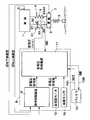
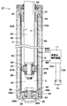
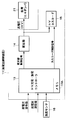
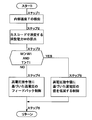
- FIG. 1 is a schematic view showing an entire configuration of a suspension control apparatus according to an embodiment of the present invention. It is a longitudinal cross-sectional view which embodies and shows damping force adjustment type shock absorber in FIG. It is a control block diagram which embodies and shows the high voltage control apparatus in FIG. It is a flowchart which shows the temperature state calculation of HV cascode by charge / discharge controller, determination of a temperature state, a voltage reduction process, etc.
- FIGS. 1 to 4 of the accompanying drawings taking a case where it is mounted on a four-wheeled vehicle.
- a vehicle body 1 constitutes a body of a vehicle.
- wheels 2 for example, left and right front wheels and left and right rear wheels are collectively referred to as a wheel 2 that together with the vehicle body 1 are provided.
- the wheel 2 is configured to include a tire 3, and the tire 3 acts as a spring that absorbs fine irregularities of the road surface.
- the suspension device 4 is provided between two relatively moving members of the vehicle (for example, between the vehicle body 1 and the wheel 2).
- the suspension device 4 includes a suspension spring 5 (hereinafter referred to as a spring 5) and a damping force adjustable type shock absorber described later disposed in parallel with the spring 5 and between the two members (between the vehicle body 1 and the wheel 2).
- Device 21 (hereinafter referred to as ER damper 21).
- FIG. 1 the case where one set of suspension devices 4 is provided between the vehicle body 1 and the wheels 2 is illustrated. However, a total of four sets of suspension devices 4 are provided independently and independently between, for example, four wheels 2 and the vehicle body 1, and only one of them is schematically shown in FIG.
- a sprung acceleration sensor 6 is provided on the vehicle body 1 side.
- the sprung acceleration sensor 6 is attached to the vehicle body 1 at a position near the ER damper 21 described later, for example.
- the sprung acceleration sensor 6 detects the upward and downward vibrational acceleration on the side of the vehicle body 1 which is a so-called sprung mass, and outputs a detection signal (that is, a signal of the sprung acceleration) to the command control device 9.
- an unsprung acceleration sensor 7 is provided on the wheel 2 side of the vehicle.
- the unsprung acceleration sensor 7 detects the upward and downward vibrational acceleration on the so-called unsprung wheel 2 side, and outputs a detection signal (that is, a signal of the unsprung acceleration) to the command control device 9.
- the on-spring acceleration sensor 6 and the on-spring acceleration sensor 7 detect the behavior of the vehicle, and more specifically, the vertical motion detection for detecting the state quantity related to the up and down movement of the vehicle Part).
- the vehicle behavior detection portion does not necessarily include the sprung acceleration sensor 6 and the unsprung acceleration sensor 7 provided in the vicinity of the ER damper 21.
- the vehicle behavior detection portion can be configured by only the sprung acceleration sensor 6.
- the vehicle behavior detection portion may be configured by a vehicle height sensor (not shown) that detects a height position (vehicle height) in the upper and lower direction of the vehicle body 1 with respect to the wheel 2.
- a vehicle speed detection portion is detected by a wheel speed sensor (not shown) for detecting the rotational speed of the wheel 2, acceleration sensors 6 and 7, and sensors for detecting the behavior (state quantity) of the vehicle other than the vehicle height sensor. It may be configured.
- the vertical motion of each wheel 2 is estimated as the vehicle behavior by, for example, estimating the vertical motion of each wheel 2 from the information (acceleration) of one sprung acceleration sensor 6 and the information (wheel speed) of the wheel speed sensor It may be configured to
- the controller 8 variably adjusts the generated damping force of the damping force adjustable shock absorber 21 (that is, the ER damper 21) based on the detection result of the vehicle behavior detection portion (for example, the acceleration sensors 6 and 7).
- Control device As shown in FIG. 1, the control device 8 includes a command control device 9 and a high voltage control device 11 described later.
- the command control device 9 of the control device 8 is disposed, for example, in a compartment of the vehicle body 1 or the like, and the high voltage control device 11 is attached to an outer cylinder 24 of an ER damper 21 described later as shown in FIG.
- the high voltage control device 11 is also an HV box that is detachably mounted on the radially outer side of the outer cylinder 24.
- the command control device 9 is called an ECU (Electronic Control Unit) for a suspension device, and includes, for example, a microcomputer. An input side of the command control device 9 is connected to the vehicle behavior detection portion (for example, the acceleration sensors 6 and 7), and an output side is connected to the high voltage control device 11. For these connections, for example, a communication line made of CAN (Controller Area Network), which is a line network for performing data communication, can be used.
- CAN Controller Area Network
- the command control device 9 obtains a high voltage command value for variably adjusting the damping force based on the detection result of the vehicle behavior detection part (for example, the acceleration sensors 6 and 7). That is, the command control device 9 variably adjusts the damping force of the ER damper 21 using, for example, the skyhook control law or the like from the vehicle behavior information input from the sprung acceleration sensor 6 and the unsprung acceleration sensor 7.
- the high voltage command value is calculated, and the high voltage command value is output to the high voltage control device 11. That is, the control device 8 including the command control device 9 and the high voltage control device 11 variably adjusts the damping force generated by the ER damper 21 which is a damping force variable damper based on the detection result of the vehicle behavior detection portion Control to do so.
- the battery 10 is a power source for applying a high voltage to the ER damper 21 (for example, an electrode cylinder 36 described later).
- the battery 10 is configured of, for example, a 12 V on-board battery (and an alternator that charges the on-board battery as needed), which is a battery for an accessory of a vehicle.
- the positive electrode side of the battery 10 is connected to the electrode cylinder 36 of the ER damper 21 via the high voltage control device 11, and the negative electrode side is connected to an outer cylinder 24 serving as a damper shell of the ER damper 21.
- the battery 10 is not only the high voltage control apparatus 11, but is also a power supply of the command control apparatus 9 grade
- a power source of the ER damper 21 for example, in the case of a hybrid car or an electric car equipped with an electric motor (drive motor) for traveling, a large capacity battery (not shown) for driving the vehicle can be used.
- the high voltage control device 11 is a device that variably controls a high voltage applied to the ER damper 21 (for example, the electrode cylinder 36).
- the high voltage control device 11 is connected to a battery 10 serving as a power supply via a battery line (batt line) 10A constituting a DC power line and a ground line (GND line) 10B.
- the high voltage control device 11 feeds back the high voltage to be applied to the electrode cylinder 36 of the ER damper 21 based on the high voltage command value output from the command control device 9 and the high voltage measurement value from the high voltage monitor 12. It is to control.
- the high voltage control device 11 is connected on the input side thereof to the command control device 9 and the high voltage monitor 12 and the like, and on the output side thereof to the electrode cylinder 36 of the ER damper 21.
- the high voltage monitor 12 monitors (monitors or detects) the high voltage boosted by the high voltage controller 11 and outputs it as a high voltage measurement value to the high voltage controller 11 for feedback control.
- the high voltage monitor 12 may be configured by, for example, a high voltage detector provided on the output side of the high voltage control device 11 or the like.
- the high voltage controller 11 includes an HV charge / discharge controller 13, a transformer 14 and an HV cascode 15. Among them, the HV charge / discharge controller 13 applies a high voltage to the electrode cylinder 36 of the ER damper 21 based on the high voltage command value output from the command control device 9 and the high voltage measurement value from the high voltage monitor 12. A transformer control signal for performing charge control of the voltage is calculated and obtained, and this transformer control signal is output to the transformer 14.
- the transformer 14 performs transformation control of a high voltage applied to the electrode cylinder 36 in accordance with the transformer control signal output from the HV charge / discharge controller 13. That is, according to the transformer control signal output from the HV charge / discharge controller 13, the transformer 14 performs, for example, transformation control to boost the DC voltage from the battery 10, and the boosted high voltage (HV) is ER
- the electrode cylinder 36 of the damper 21 is supplied (output).
- the HV charge / discharge controller 13 performs discharge control so as to step down the voltage applied to the electrode cylinder 36 of the ER damper 21. That is, the HV charge / discharge controller 13 controls the discharge of the high voltage applied to the electrode cylinder 36 based on the high voltage command value output from the command control device 9 and the high voltage measurement value from the high voltage monitor 12. To calculate the cascode control signal for performing the above, and the cascode control signal is output to the HV cascode 15.
- the HV cascode 15 of the high voltage control device 11 constitutes a discharge circuit for discharging the high voltage applied to the electrode cylinder 36 to lower the charge.
- the HV cascode 15 performs discharge control of the high voltage (HV) applied to the electrode cylinder 36 according to the cascode control signal from the HV charge / discharge controller 13, and excess charge remains in the electrode cylinder 36 at the time of discharge. In order to prevent this, the potential of the electrode cylinder 36 is reduced early with high responsiveness.
- the HV charge / discharge controller 13 of the high voltage control device 11 controls the transformer 14 and the HV cascode 15 in parallel (parallel) so that the transformer 14 and the HV cascode 15 do not operate at the same time. There is. For this reason, from the HV charge / discharge controller 13, the transformer control signal and the cascode control signal are output so as to have characteristics of rising at different times, that is, with a time difference.
- the HV charge / discharge controller 13 controls the analog control signal (transformer control signal) according to the difference between the high voltage command value (high voltage request) output from the command control device 9 and the high voltage measurement value from the high voltage monitor 12. generate. This signal is sent to the transformer 14 which generates a high voltage proportional to the transformer control signal. Further, the HV charge / discharge controller 13 calculates a digital signal (cascode control signal) based on the high voltage command value (high voltage request) and the high voltage measurement value in parallel with this. This signal is converted to an analog signal and sent to the HV cascode 15.
- the HV charge / discharge controller 13 is provided with a memory 13A as a storage device configured of, for example, a non-volatile memory, a ROM, and / or a RAM.
- the memory 13A includes, for example, a process program for calculating the temperature state of the HV cascode 15, a process for determining the temperature state, a voltage reduction process, and the like as shown in FIG.
- the predetermined judgment value W1 etc. of the temperature T1 and the power consumption W are stored.
- the determination value W1 of the power consumption W is a power value for determining whether or not the power consumption W of the HV cascode 15 exceeds the threshold power, and when the power consumption W exceeds the determination value W1, the HV The temperature state of the cascode 15 can be determined to have risen to a non-negligible temperature state in order to maintain and secure the durability and life of the HV cascode 15.
- the threshold temperature T1 is such that the internal temperature T of the high voltage controller 11 (that is, the base temperature including the substrate of the high voltage controller 11) becomes high, and the configuration of the high voltage controller 11 including the HV cascode 15
- the temperature of the parts is set to a temperature that may adversely affect the durability and life of the parts.
- the temperature state of the HV cascode 15 can be obtained by adding the heat generation amount (power consumption W) of the HV cascode 15 to the internal temperature T of the high voltage control device 11. Therefore, when the power consumption W of the HV cascode 15 exceeds the determination value W1 (W> W1) and the internal temperature T exceeds the threshold temperature T1 (T> T1), the temperature condition of the HV cascode becomes the threshold. It can be judged that the temperature state is exceeded, and the durability of the HV cascode 15 and the temperature state of the boundary where the life starts to decrease is reached.
- the HV charge / discharge controller 13 performs a process of calculating the temperature state of the HV cascode 15 as in steps 1 and 2 in FIG. 4 and the temperature condition calculator of the HV cascode 15 obtained by this temperature state calculator. And a voltage reduction device that reduces the value of the high voltage based on the high voltage command value as shown in step 6 in FIG. 4 when the temperature state exceeds a threshold temperature state.
- the temperature sensor 16 is a temperature detection device that detects the internal temperature of the high voltage control device 11.
- the temperature sensor 16 may be, for example, a temperature sensor built in a CPU (not shown) of the high voltage control device 11, or may be a temperature sensor that detects the temperature of the environment surrounding the vehicle. .
- the temperature detection device may be configured by the input data at this time.
- the temperature data of the air-conditioned vehicle room or the temperature data of the engine compartment having a heating element can not be used as data of the temperature detection device.
- the configuration of the damping force adjustable shock absorber 21 (that is, the ER damper 21) constituting the main part of the suspension device 4 will be described with reference to FIG. 1 and FIG.
- one end side of the ER damper 21 in the axial direction is referred to as the “lower end” side
- the other end side in the axial direction is referred to as the “upper end” side
- the other end side in the axial direction may be the “lower end” side.
- the ER damper 21 is a damping force variable shock absorber that damps vertical movement of the vehicle body 1 and the wheel 2.
- the ER damper 21 is configured as a damping force adjustable semi-active damper using a liquid electro-rheological fluid 22 as a working fluid sealed inside.
- Electrorheological fluid (ERF: Electro Rheological Fluid) 22 is a functional fluid whose property (viscosity) changes in response to an externally applied electric field (voltage).
- the electro-rheological fluid 22 (hereinafter referred to as the ER fluid 22) is prepared by mixing (dispersing) a base oil (base oil) comprising, for example, silicone oil etc. with the base oil, and the viscosity can be changed according to the change of the electric field. And particles (fine particles) to be increased or decreased.
- the ER fluid 22 has its viscosity increased or decreased according to the applied voltage, and the flow resistance (damping force) changes.
- the ER damper 21 is configured to include an inner cylinder 23, an outer cylinder 24, a piston 27, a piston rod 30, a bottom valve 32, an electrode cylinder 36 and the like.
- the inner cylinder 23 and the outer cylinder 24 constitute a cylinder, and an ER fluid 22 is enclosed in the cylinder.
- the ER fluid 22 enclosed is shown as colorless and transparent.
- the inner cylinder 23 is formed as a cylindrical cylinder extending in the axial direction.
- a piston rod 30 is inserted into the inner cylinder 23.
- An outer cylinder 24 and an electrode cylinder 36 are coaxially provided on the outer side of the inner cylinder 23.
- a plurality of (for example, 4 to 8) oil holes 23A, which are always communicated with an interelectrode passage 39 described later, are formed in the inner cylinder 23 as circumferential holes in the radial direction. That is, the rod side oil chamber B in the inner cylinder 23 is in communication with the interelectrode passage 39 through the respective oil holes 23A.
- the outer cylinder 24 forms an outer shell of the ER damper 21 and is formed as a cylindrical body.
- the outer cylinder 24 is provided radially outward of the electrode cylinder 36, and the reservoir chamber A is formed between the outer cylinder 24 and the electrode cylinder 36.
- the outer cylinder 24 is a closed end whose lower end side is closed by the bottom cap 25.
- the upper end side of the outer cylinder 24 is an open end.
- a seal member 26 is provided on the open end side of the outer cylinder 24 to seal the space between the piston rod 30 and the air- and liquid-tight.
- An annular reservoir chamber A serving as a reservoir is formed between the inner cylinder 23 and the outer cylinder 24 (more specifically, between the electrode cylinder 36 and the outer cylinder 24).
- a gas to be a working gas is enclosed in the reservoir chamber A, together with the ER fluid 22, a gas to be a working gas is enclosed.
- This gas may be air at atmospheric pressure, or a gas such as compressed nitrogen gas may be used.
- the gas in the reservoir chamber A is compressed to compensate for the approach volume of the piston rod 30 when the piston rod 30 contracts (contracts).
- the piston 27 is provided slidably in the inner cylinder 23.
- the piston 27 defines the inside of the inner cylinder 23 into a rod side oil chamber B as a first chamber and a bottom side oil chamber C as a second chamber.
- a plurality of oil passages 27A, 27B enabling communication between the rod side oil chamber B and the bottom side oil chamber C are formed on the piston 27 so as to be separated from each other in the circumferential direction.
- the ER damper 21 has a uniflow structure. Therefore, the ER fluid 22 in the inner cylinder 23 travels from the rod side oil chamber B (that is, the oil hole 23A of the inner cylinder 23) to the interelectrode passage 39 in both the compression stroke and the expansion stroke of the piston rod 30. It flows in one direction (that is, in the direction of an arrow F shown by a two-dot chain line in FIG. 2).
- a compression side check valve 28 is provided on the upper end surface of the piston 27.
- the contraction side check valve 28 opens when the piston 27 slides downward in the inner cylinder 23 in the contraction stroke of the piston rod 30, and closes at other times.
- the contraction-side check valve 28 allows the oil (ER fluid 22) in the bottom-side oil chamber C to flow in the respective oil passages 27A toward the rod-side oil chamber B, in the opposite direction to this. Stop the fluid from flowing.
- the lower end surface of the piston 27 is provided with a disk valve 29 on the extension side.
- the pressure in the rod side oil chamber B exceeds the relief set pressure when the piston 27 slides and displaces upward in the inner cylinder 23 in the extension stroke (extension stroke) of the piston rod 30 on the extension side disk valve 29. And the pressure at this time is relieved to the bottom side oil chamber C side via each oil passage 27B.
- the lower end of the piston rod 30 is connected (fixed) to the piston 27 in the inner cylinder 23, and the upper end is extended to the outside of the inner cylinder 23 and the outer cylinder 24 through the rod side oil chamber B.
- the upper end side of the piston rod 30 protrudes to the outside through the rod guide 31.
- the rod guide 31 is a member for guiding the piston rod 30 axially slidably on the inner peripheral side thereof.
- a bottom valve 32 is provided on the lower end side of the inner cylinder 23.
- the bottom valve 32 serves to connect and shut off the bottom side oil chamber C and the reservoir chamber A.
- the bottom valve 32 is configured to include a valve body 33, an expansion side check valve 34, and a disc valve 35.
- the valve body 33 defines the reservoir chamber A and the bottom side oil chamber C between the outer cylinder 24, the bottom cap 25 and the inner cylinder 23.
- oil passages 33A and 33B enabling communication between the reservoir chamber A and the bottom side oil chamber C are formed at intervals in the circumferential direction.
- the expansion side check valve 34 is provided, for example, on the upper surface side of the valve body 33.
- the extension check valve 34 opens when the piston 27 slides upward in the extension stroke of the piston rod 30, and closes otherwise.
- the expansion side check valve 34 allows the oil (ER fluid 22) in the reservoir chamber A to flow in the respective oil passages 33A toward the bottom side oil chamber C, and the oil in the opposite direction to this. Stop the flow.
- the disc valve 35 on the reduction side is provided on the lower surface side of the valve body 33.
- the reduction-side disk valve 35 opens when the pressure in the bottom-side oil chamber C exceeds the relief setting pressure when the piston 27 slides downward in the reduction stroke of the piston rod 30, and the pressure at this time Are relieved to the reservoir chamber A side via each oil passage 33B.
- an electrode cylinder 36 formed of an intermediate cylinder (pressure pipe) extending in the axial direction is provided between the inner cylinder 23 and the outer cylinder 24, an electrode cylinder 36 formed of an intermediate cylinder (pressure pipe) extending in the axial direction is provided.
- the electrode cylinder 36 is supported by the rod guide 31 and the valve body 33 via holding members 37 and 38.
- the holding members 37 and 38 are formed of, for example, an electrically insulating material (isolator).
- the upper holding member 37 keeps the inner cylinder 23, the rod guide 31 and the electrode cylinder 36 in an electrically insulated state.
- the lower holding member 38 keeps the inner cylinder 23, the valve body 33, and the electrode cylinder 36 in an electrically insulated state.
- the lower holding member 38 is formed with a plurality of oil passages 38A that allow the interelectrode passage 39 to communicate with the reservoir chamber A.
- the electrode cylinder 36 is disposed as an intermediate cylinder between the inner cylinder 23 and the outer cylinder 24.
- the electrode cylinder 36 is formed using a conductive material, and constitutes a cylindrical positive (plus side) electrode. That is, a high voltage (HV) is applied to the electrode cylinder 36 from the high voltage controller 11.
- the inner cylinder 23 radially opposed to the electrode cylinder 36 constitutes a cylindrical negative (minus side) electrode, and is electrically connected to the outer cylinder 24 via the valve body 33 and the like.
- an annular inter-electrode passage 39 is formed extending in the axial direction and in communication with the rod side oil chamber B via the plurality of oil holes 23A.
- the interelectrode passage 39 is a portion where the flow of the ER fluid 22 occurs, and the electrode cylinder 36 is an electrode that applies an electric field to the ER fluid 22 in the interelectrode passage 39.
- a partition member 40 is provided which partitions the inter-electrode passage 39 through which the ER fluid 22 flows (guides the flow of the ER fluid 22).
- the partition member 40 is attached to the outer peripheral surface of the inner cylinder 23 and the inner peripheral surface of the electrode cylinder 36 so as not to be relatively rotatable.
- the partition member 40 is a flow path forming member for guiding the ER fluid 22 not only in the axial direction but also in the circumferential direction between the inner cylinder 23 and the electrode cylinder 36.
- the inter-electrode passage 39 through which the ER fluid 22 flows can be made into one or a plurality of spiral or meandering passages (flow passages) having a circumferentially extending portion.
- the overall length of the interelectrode passage 39 (the length of the flow passage from the oil hole 23A to the oil passage 38A) can be increased as compared with the passage extending linearly in the axial direction.
- the ER fluid 22 in the interelectrode passage 39 moves along the interelectrode passage as the piston rod 30 moves back and forth in the inner cylinder 23 (that is, while the contraction and extension strokes are repeated). It flows from the upper side to the lower side in the axial direction of 39. Then, the ER fluid 22 flowing into the interelectrode passage 39 flows out from the lower end side of the electrode cylinder 36 to the reservoir chamber A via the oil passage 38A of the holding member 38. At this time, in the interelectrode passage 39, an electric field (potential difference) corresponding to the high voltage applied to the electrode cylinder 36 is generated, so the viscosity of the ER fluid 22 is variably adjusted according to the electric field strength.
- the ER damper 21 generates an electric field (potential difference) in the interelectrode passage 39 between the inner cylinder 23 and the electrode cylinder 36, and the viscosity of the ER fluid 22 passing through the interelectrode passage 39 corresponds to the electric field.
- the generated damping force can be variably controlled (adjusted).
- the viscosity of the ER fluid 22 is increased or decreased according to the electric field strength (potential difference) between the inner cylinder 23 and the electrode cylinder 36, and the higher the high voltage (HV) applied from the high voltage control device 11, the generated damping force becomes a hard property and increases.
- the ER damper 21 changes the characteristic (damping force characteristic) of the generated damping force to a high voltage according to the increase or decrease of the high voltage (HV) applied to the electrode cylinder 36 provided in the portion where the ER fluid 22 flows.
- the adjustment can be made continuously between the time hard characteristics (hard characteristics) and the low voltage soft characteristics (soft characteristics).
- the ER damper 21 does not necessarily have to change the damping force characteristics continuously, and may be configured to be adjustable in two or more stages.
- the suspension control device has the configuration as described above. Next, the damping force characteristic of the ER damper 21 is variably controlled using the command control device 9 of the control device 8 and the high voltage control device 11 The process to be performed will be described.
- the command control device 9 receives a detection signal corresponding to the sprung acceleration from the sprung acceleration sensor 6 and a detection signal corresponding to the unsprung acceleration from the unsprung acceleration sensor 7. At this time, the command control device 9 calculates a target damping force from the sprung acceleration and the unsprung upper speed using, for example, a skyhook control law, and calculates a target voltage necessary to generate the target damping force. Do. Then, the command control device 9 outputs a high voltage command value corresponding to the target damping force (target voltage) to the high voltage control device 11.
- a high voltage measurement value from, for example, the high voltage monitor 12 is input to the high voltage control device 11.
- the high voltage measurement value is obtained by monitoring (monitoring) a high voltage which is boosted by the high voltage control device 11 and applied to the electrode cylinder 36.
- This high voltage measurement value is for feedback control of the high voltage control device 11.
- Used for The high voltage monitor 12 can be configured by, for example, a high voltage detector provided on the output side of the high voltage control device 11, and in FIG. 1, one portion for clearly indicating the high voltage measurement value.
- the high voltage monitor 12 is illustrated in FIG.
- the command control device 9 outputs a high voltage command value to the high voltage control device 11.
- the HV charge / discharge controller 13 of the high voltage control device 11 calculates a transformer control signal based on the high voltage command value and the high voltage measurement value, and outputs this to the transformer 14.
- the transformer 14 performs transformation control so that, for example, the DC voltage from the battery 10 is boosted according to the transformer control signal, and outputs the boosted high voltage (HV) to the electrode cylinder 36 of the ER damper 21. That is, the HV charge / discharge controller 13 receives the high voltage command value (high voltage request), and when the request is increasing, the DC voltage is increased until the output voltage (HV) of the transformer 14 reaches the required voltage value. Perform transformation control to boost.
- the transformer 14 stops the transformer control for boosting to generate energy.
- the HV charge / discharge controller 13 performs discharge control of the HV cascode 15 to reduce the high voltage.
- the HV charge / discharge controller 13 performs cascode control in accordance with a cascode control algorithm determined in advance based on the high voltage command value output from the command control device 9 and the high voltage measurement value from the high voltage monitor 12. The signal is calculated and this cascode control signal is output to the HV cascode 15.
- the HV cascode 15 performs discharge control of the high voltage (HV) applied to the electrode cylinder 36 according to the cascode control signal, so that the charge of the high voltage (HV) is easily released from the electrode cylinder 36 and the discharge time is shortened. can do. For this reason, the potential of the electrode cylinder 36 can be quickly reduced with high responsiveness, and the responsiveness of damping force control can be improved.
- the HV charge / discharge controller 13 outputs the cascode control signal to the HV cascode 15 and causes the HV cascode 15 to perform discharge control of the high voltage (HV) applied to the electrode cylinder 36, thereby the ER damper
- HV high voltage
- the application of high voltage to the electrode cylinder 36 and the discharge control can be performed with high responsiveness, and the reliability and stability of damping force control can be enhanced.
- the current for discharge flows through the HV cascode 15 and the HV cascode 15 generates heat due to the consumed power.
- the calorific value of the HV cascode 15 increases, the durability and the life decrease.
- the control processing shown in FIG. 4 is executed to suppress the heat generation of the HV cascode 15. That is, when the processing operation of FIG. 4 starts, the HV charge / discharge controller 13 detects the internal temperature T of the high voltage control device 11 based on the signal from the temperature sensor 16 in step 1.
- the power consumption W consumed by the HV cascode 15 is calculated. That is, since the HV cascode 15 consumes power by the current flowing at the time of discharge from the electrode cylinder 36, the power consumption W is calculated as the heat generation amount of the HV cascode 15.
- the power consumption W is determined by performing integral calculation from the history of the transformer control signal (high voltage control) and the cascode control signal (discharge control) described above. , Temperature change due to heat generation of the HV cascode 15 is estimated.
- the next step 3 it is determined whether the power consumption W of the HV cascode 15 exceeds the power of the predetermined determination value W1 (W> W1), and the internal temperature T of the high voltage control device 11 is determined in advance. It is determined whether the threshold temperature T1 has been exceeded (T> T1). That is, the temperature state of the HV cascode 15 can be obtained by adding the heat generation amount (power consumption W) of the HV cascode 15 to the internal temperature T of the high voltage control device 11.
- step 3 when "NO" is determined in step 3, the above-mentioned AND condition is not satisfied, and the temperature condition of the HV cascode 15 is high temperature condition which adversely affects the durability and the life. It can be judged that there is no. Therefore, in the next step 4, the high voltage to be applied to the electrode cylinder 36 of the ER damper 21 based on the high voltage command value output from the command control device 9 and the high voltage measurement value from the high voltage monitor 12 Feedback control. Then, in the next step 5, the process returns and continues the processing of step 1 and subsequent steps.
- step 3 determines whether "YES" is determined in the step 3 or "YES" is satisfied, and the temperature condition of the HV cascode 15 adversely affects the durability and the life of the HV cascode 15, for example. It can be determined that the temperature is rising. Therefore, in the next step 6, control is performed to reduce the value of the high voltage based on the high voltage command value, and the voltage applied to the electrode cylinder 36 of the ER damper 21 is a predetermined gain G (for example, G is reduced by 0.2 to 0.7). For example, the high voltage of 5000V is reduced to 1000-3500V. Then, in the next step 5, the process returns and continues the processing of step 1 and subsequent steps.
- G is reduced by 0.2 to 0.7
- the high voltage control device 11 for feedback controlling the high voltage applied to the electrode cylinder 36 of the ER damper 21 is controlled to the electrode cylinder 36 based on the high voltage command value from the command control device 9.
- An HV charge / discharge controller 13 outputting a transformer control signal for performing charge control of a high voltage to be applied and a cascode control signal for discharge control of the high voltage, and transformation from the charge / discharge controller 13 Transformer 14 that performs high voltage transformation control of high voltage applied to the electrode cylinder 36 according to the control signal and HV cascode that performs discharge control of high voltage applied to the electrode cylinder 36 according to the cascode control signal from the charge / discharge controller 13 And 15).
- the HV charge / discharge controller 13 calculates the temperature state associated with the heat generation of the HV cascode 15 including the internal temperature by the temperature detection device (temperature sensor 16) (step 1 in FIG. 4) 2) and a voltage reduction device that reduces the value of the high voltage based on the high voltage command value when the temperature condition of the HV cascode 15 determined by the temperature condition calculation device exceeds the threshold temperature condition (step 6) and is comprised.
- the HV charge / discharge controller 13 determines that the calorific value of the HV cascode 15 is large, and the temperature state of the HV cascode 15 is increased to a temperature that can not be ignored such that the durability and life thereof decrease. When this is done, control is performed to reduce the value of the high voltage based on the high voltage command value. As a result, excessive heat generation of the HV cascode 15 can be suppressed, and the durability and the life of the entire device including the HV cascode 15 can be prevented from being reduced, and the reliability can be ensured.
- the high voltage (HV) charge is easily released from the electrode cylinder 36, and application of high voltage to the electrode cylinder 36 of the ER damper 21 and discharge control Can be performed with high responsiveness, and the reliability and stability of damping force control can be enhanced.
- the temperature state of the high voltage control device 11 can be estimated and calculated from the power consumption W of the HV cascode 15 without using an expensive temperature sensor.
- the temperature sensor 16 for detecting the internal temperature T of the high voltage control device 11 may be an existing sensor.
- the temperature condition calculation device of the HV charge / discharge controller 13 calculates the temperature condition of the HV cascode 15 from the power consumption W consumed by the discharge of the HV cascode 15 and the internal temperature T by the temperature sensor 16. Do. That is, as shown in steps 1 and 2 shown in FIG. 4, a process of calculating the temperature state of the HV cascode 15 is executed.
- step 3 of FIG. 4 it is determined whether the power consumption W of the HV cascode 15 exceeds the power of the predetermined determination value W1 (W> W1), and the internal temperature of the high voltage control device 11 It is determined whether T exceeds a predetermined threshold temperature T1 (T> T1).
- T a predetermined threshold temperature
- the temperature state of the HV cascode 15 is based on the internal temperature T of the high voltage control device 11 and the heat generation amount (power consumption W) of the HV cascode 15 is added to the base temperature to obtain the temperature of the HV cascode 15
- the state can be calculated, and it can be determined whether the temperature state of the HV cascode 15 has risen to such a temperature that the durability and the life decrease.
- the voltage reduction device is configured to reduce the high voltage by multiplying a value of the high voltage based on the high voltage command value by a predetermined gain G.
- the voltage applied to the electrode cylinder 36 of the ER damper 21 can be reduced by a predetermined gain G, and the current flowing through the HV cascode 15 can be reduced for discharging. Therefore, excessive heat generation of the HV cascode 15 can be suppressed, and the durability and life of the entire apparatus including the HV cascode 15 can be extended.
- the ER damper 21 of the suspension device 4 is mounted vertically on a vehicle such as a car.
- the present invention is not limited to this.
- the ER damper 21 may be configured to be attached to a vehicle such as a railway vehicle in a state of being placed horizontally. That is, the ER damper 21 can be installed in a desired direction in accordance with the object to be attached, for example, by arranging the ER damper 21 in an inclined manner in a range that does not cause aeration.
- suspension control device based on the embodiment described above, for example, one having an aspect described below can be considered.
- a damping force adjustable shock absorber provided between two members moving relative to the vehicle, and the vehicle behavior detection portion Control device for adjusting the damping force of the damping force adjustable shock absorber
- the damping force adjustable shock absorber is a cylinder in which an electro-rheological fluid is enclosed and slidably inserted in the cylinder A piston, a piston rod connected to the piston and extending to the outside of the cylinder, and a portion where the flow of the electro-rheological fluid is generated by the sliding of the piston in the cylinder, the electro-rheological fluid
- a suspension control device comprising an electrode for applying an electric field to the vehicle, wherein the control device is a high voltage for variably adjusting the damping force based on the detection result of the vehicle behavior detection portion
- a high voltage control device for feedback controlling a high voltage applied to the electrode based on the high voltage command value output from the command control device; and an internal temperature of the high
- a charge / discharge controller for outputting a cascode control signal for performing discharge control, a transformer for performing transformation control of a high voltage applied to the electrode according to a transformer control signal from the charge / discharge controller, and the charge
- An HV cascode for performing discharge control of a high voltage applied to the electrode in accordance with a cascode control signal from a discharge controller;
- the roller calculates the temperature state associated with the heat generation of the HV cascode including the internal temperature by the temperature detecting device, and the temperature at which the temperature state of the HV cascode obtained by the temperature state computing device becomes a threshold And a voltage reduction device that reduces the value of the high voltage based on the high voltage command value when the state is exceeded.
- the temperature state calculating device calculates the temperature state of the HV cascode from the power consumption consumed by the discharge of the HV cascode and the internal temperature by the temperature detecting device.
- the voltage reduction device reduces the high voltage by multiplying the value of the high voltage based on the high voltage command value by a predetermined gain. It is supposed to be configured.
- the present invention is not limited to the above-described embodiment, but includes various modifications.
- the above-described embodiment is described in detail to explain the present invention in an easy-to-understand manner, and is not necessarily limited to one having all the described configurations.
- part of the configuration of one embodiment can be replaced with the configuration of another embodiment, and the configuration of another embodiment can be added to the configuration of one embodiment.
Landscapes
- Engineering & Computer Science (AREA)
- General Engineering & Computer Science (AREA)
- Mechanical Engineering (AREA)
- Physics & Mathematics (AREA)
- Electromagnetism (AREA)
- Acoustics & Sound (AREA)
- Aviation & Aerospace Engineering (AREA)
- Vehicle Body Suspensions (AREA)
- Fluid-Damping Devices (AREA)
Abstract
ERダンパの電極筒に印加する高電圧をフィードバック制御する高電圧制御装置は、充電・放電コントローラ、変圧器およびHVカスコードを有している。充電・放電コントローラは、HVカスコードの発熱に伴う温度状態を温度検出装置(温度センサ)による高電圧制御装置の内部温度を含めて演算する温度状態演算装置と、前記温度状態演算装置で求めたHVカスコードの温度状態が閾値となる温度状態を超えたときに前記高電圧指令値に基づいた前記高電圧の値を低減させる電圧低減装置と、を含んで構成されている。
Description
本発明は、例えば4輪自動車等の車両に搭載されるサスペンション制御装置に関する。
4輪自動車等の車両には車体(ばね上)側と各車輪(ばね下)側との間に、例えばサスペンションとしての減衰力調整式緩衝器(ダンパ)が設けられている。この種の関連技術として、シリンダ内に電気粘性流体(ERF:Electro Rheological Fluid)を封入した状態で、高電圧による電界を付与することにより発生減衰力を可変に制御する構成とした減衰力調整式緩衝器(ERダンパ)が知られている(例えば、特許文献1参照)。
ところで、ERダンパは、内部に封入した電気粘性流体が大きな時定数をもっている。このため、電気粘性流体に電界をかける電極に対し、高電圧(HV)を印加したり、この高電圧(HV)を電極から放電させたりする制御には余分な時間がかかる。そこで、カスコード回路を用いて高電圧の放電制御を行うことを検討した。しかし、カスコード回路は放電制御を続けると、発熱量が大きくなって、耐久性、寿命が低下するという問題がある。
本発明の目的は、減衰力制御の応答性を良好にしつつ、過大な発熱を抑えて耐久性、寿命を確保することができるようにしたサスペンション制御装置を提供することにある。
本発明の一実施形態に係るサスペンション制御装置は、車両の挙動を検出する車両挙動検出部分と、前記車両の相対移動する2部材間に設けられた減衰力調整式緩衝器と、前記車両挙動検出部分の検出結果に基づいて前記減衰力調整式緩衝器の減衰力を調整するよう制御する制御装置と、を有し、前記減衰力調整式緩衝器は、電気粘性流体が封入されたシリンダと、該シリンダ内に摺動可能に挿入されたピストンと、該ピストンに連結されて前記シリンダの外部に延出するピストンロッドと、前記シリンダ内の前記ピストンの移動によって前記電気粘性流体の流れが生じる部分に設けられ、前記電気粘性流体に電界をかける電極と、を含んでなるサスペンション制御装置に適用される。
そして、前記制御装置は、前記車両挙動検出部分の検出結果に基づいて前記減衰力を可変に調整するための高電圧指令値を求める指令制御装置と、前記指令制御装置から出力される前記高電圧指令値に基づいて前記電極に印加する高電圧をフィードバック制御する高電圧制御装置と、前記高電圧制御装置の内部温度を検出する温度検出装置と、を備えており、前記高電圧制御装置は、前記高電圧指令値に基づいて前記電極に印加する高電圧の充電制御を行うための変圧器制御信号と前記高電圧の放電制御を行うためのカスコード制御信号とを出力する充電・放電コントローラと、前記充電・放電コントローラからの変圧器制御信号に従って前記電極に印加する高電圧の変圧制御を行う変圧器と、前記充電・放電コントローラからのカスコード制御信号に従って前記電極に印加された高電圧の放電制御を行うHVカスコードと、を有し、前記充電・放電コントローラは、前記HVカスコードの発熱に伴う温度状態を前記温度検出装置による内部温度を含めて演算する温度状態演算装置と、前記温度状態演算装置で求めた前記HVカスコードの温度状態が閾値となる温度状態を超えたときに前記高電圧指令値に基づいた前記高電圧の値を低減させる電圧低減装置と、を含んで構成されている。
本発明の一実施形態に係るサスペンション制御装置は、減衰力制御を行うときの応答性を良好にできると共に、HVカスコードの発熱量が大きくなるのを抑えることができ、耐久性、寿命を向上することができる。
以下、本発明の実施の形態によるサスペンション制御装置を、4輪自動車に搭載した場合を例に挙げ、添付図面の図1ないし図4に従って詳細に説明する。
図1において、車体1は、車両のボディを構成している。車体1の下側には、車体1と共に車両を構成する車輪2(例えば、左,右の前輪と左,右の後輪を総称して車輪2という)が設けられている。この車輪2は、タイヤ3を含んで構成され、タイヤ3は、路面の細かい凹凸を吸収するばねとして作用する。
サスペンション装置4は、車両の相対移動する2部材間(例えば、車体1と車輪2との間)に設けられている。サスペンション装置4は、懸架ばね5(以下、ばね5という)と、該ばね5と並列になって前記2部材間(車体1と車輪2との間)に設けられた後述の減衰力調整式緩衝器21(以下、ERダンパ21という)とを含んで構成されている。なお、図1中では、1組のサスペンション装置4を車体1と車輪2との間に設けた場合を例示している。しかし、サスペンション装置4は、例えば4輪の車輪2と車体1との間に個別に独立して合計4組設けられるもので、このうちの1組のみを図1では模式的に示している。
車体1側にはばね上加速度センサ6が設けられている。このばね上加速度センサ6は、例えば後述するERダンパ21の近傍となる位置で車体1に取付けられている。ばね上加速度センサ6は、所謂ばね上側となる車体1側で上,下方向の振動加速度を検出し、その検出信号(即ち、ばね上加速度の信号)を指令制御装置9に出力する。一方、車両の車輪2側にはばね下加速度センサ7が設けられている。このばね下加速度センサ7は、所謂ばね下側となる車輪2側で上,下方向の振動加速度を検出し、その検出信号(即ち、ばね下加速度の信号)を指令制御装置9に出力する。
ここで、ばね上加速度センサ6とばね下加速度センサ7は、車両の挙動を検出する車両挙動検出部分(より具体的には、車両の上,下方向の運動に関する状態量を検出する上下運動検出部分)を構成している。なお、車両挙動検出部分は、ERダンパ21の近傍に設けたばね上加速度センサ6とばね下加速度センサ7とを含んで必ずしも構成する必要はない。例えば、ばね上加速度センサ6だけで車両挙動検出部分を構成することもできる。また、車両挙動検出部分は、車輪2に対する車体1の上,下方向の高さ位置(車高)を検出する車高センサ(図示せず)により構成してもよい。
さらには、車輪2の回転速度を検出する車輪速センサ(図示せず)等、加速度センサ6,7、前記車高センサ以外の車両の挙動(状態量)を検出するセンサにより車両挙動検出部分を構成してもよい。この場合、例えば1個のばね上加速度センサ6の情報(加速度)と車輪速センサの情報(車輪速)から各車輪2毎の上下運動を推定することで、車両の上下運動を車両挙動として検出する構成としてもよい。
制御装置8は、前記車両挙動検出部分(例えば、加速度センサ6,7)の検出結果に基づいて減衰力調整式緩衝器21(即ち、ERダンパ21という)の発生減衰力を可変に調整するための制御装置である。この制御装置8は、図1中に示すように、指令制御装置9と後述の高電圧制御装置11とを備えている。制御装置8の指令制御装置9は、例えば車体1の車室内等に配設され、高電圧制御装置11は、後述するERダンパ21の外筒24に図2に示す如く付設される。高電圧制御装置11は、外筒24の径方向外側に着脱可能に取付けられるHVボックスでもある。
指令制御装置9は、サスペンション装置用のECU(Electronic Control Unit)と呼ばれるもので、例えばマイクロコンピュータを含んで構成されている。指令制御装置9は、その入力側が前記車両挙動検出部分(例えば、加速度センサ6,7)に接続され、出力側は高電圧制御装置11に接続されている。これらの接続には、例えばデータ通信を行う回線網であるCAN(Controller Area Network)からなる通信線を用いることができる。
指令制御装置9は、前記車両挙動検出部分(例えば、加速度センサ6,7)の検出結果に基づいて前記減衰力を可変に調整するための高電圧指令値を求める。即ち、指令制御装置9は、ばね上加速度センサ6とばね下加速度センサ7とから入力された車両挙動情報から、例えばスカイフック制御則等を用いてERダンパ21の減衰力を可変に調整するための高電圧指令値を算出し、この高電圧指令値を高電圧制御装置11に出力する。即ち、指令制御装置9と高電圧制御装置11とからなる制御装置8は、減衰力可変ダンパであるERダンパ21で発生する減衰力を、記車両挙動検出部分の検出結果に基づいて可変に調整するように制御する。
図1に示すように、バッテリ10は、ERダンパ21(例えば、後述の電極筒36)に高電圧を印加するための電源となっている。バッテリ10は、例えば車両の補機用バッテリとなる12Vの車載バッテリ(および、必要に応じて車載バッテリの充電を行うオルタネータ)により構成されている。バッテリ10は、正極側が高電圧制御装置11を介してERダンパ21の電極筒36に接続され、負極側はERダンパ21のダンパシェルとなる外筒24に接続されている。なお、バッテリ10は、高電圧制御装置11に限らず、例えば指令制御装置9等の電源でもあるが、図面の簡略化のために図示は省略している。また、ERダンパ21の電源は、例えば、走行用の電動モータ(駆動モータ)が搭載されたハイブリッド自動車や電気自動車の場合、車両駆動用の大容量バッテリ(図示せず)を用いることもできる。
高電圧制御装置11は、ERダンパ21(例えば、電極筒36)に印加する高電圧を可変に制御する装置である。このために、高電圧制御装置11は、直流電力線を構成するバッテリ線(batt線)10Aとグランド線(GND線)10Bとを介して電源となるバッテリ10に接続されている。高電圧制御装置11は、指令制御装置9から出力される前記高電圧指令値と高電圧モニタ12からの高電圧測定値とに基づいて、ERダンパ21の電極筒36に印加する高電圧をフィードバック制御するものである。
高電圧制御装置11は、その入力側が指令制御装置9および高電圧モニタ12等に接続され、出力側はERダンパ21の電極筒36に接続されている。高電圧モニタ12は、高電圧制御装置11で昇圧された高電圧をモニタ(監視または検出)し、これを高電圧測定値として高電圧制御装置11にフィードバック制御のために出力する。なお、高電圧モニタ12は、例えば高電圧制御装置11の出力側に設けた高電圧の検出器等により構成してもよい。
図3に示すように、高電圧制御装置11は、HV充電・放電コントローラ13、変圧器14およびHVカスコード15を含んで構成されている。このうち、HV充電・放電コントローラ13は、指令制御装置9から出力される高電圧指令値と高電圧モニタ12からの高電圧測定値とに基づいて、ERダンパ21の電極筒36に印加する高電圧の充電制御を行うための変圧器制御信号を演算して求め、この変圧器制御信号を変圧器14に出力する。
この変圧器14は、HV充電・放電コントローラ13から出力される前記変圧器制御信号に従って電極筒36に印加する高電圧の変圧制御を行うものである。即ち、変圧器14は、HV充電・放電コントローラ13から出力される前記変圧器制御信号に従って、例えばバッテリ10からの直流電圧を昇圧させるように変圧制御し、昇圧された高電圧(HV)をERダンパ21の電極筒36に供給(出力)する。
また、HV充電・放電コントローラ13は、ERダンパ21の電極筒36に印加される電圧を降圧させるように放電制御を行う。即ち、HV充電・放電コントローラ13は、指令制御装置9から出力される高電圧指令値と高電圧モニタ12からの高電圧測定値とに基づいて、電極筒36に印加される高電圧の放電制御を行うためのカスコード制御信号を演算して求め、このカスコード制御信号をHVカスコード15に出力する。
高電圧制御装置11のHVカスコード15は、電極筒36に印加された高電圧を放電して電荷を下げるための放電回路を構成している。このHVカスコード15は、HV充電・放電コントローラ13からの前記カスコード制御信号に従って電極筒36に印加された高電圧(HV)の放電制御を行い、放電時に電極筒36に余分な電荷が残るのを防ぐため、電極筒36の電位を早期に高い応答性で低下させるものである。
ここで、高電圧制御装置11のHV充電・放電コントローラ13は、変圧器14とHVカスコード15とが同時に作動しないように、変圧器14とHVカスコード15とを並行(並列的)に制御している。このため、HV充電・放電コントローラ13からは、前記変圧器制御信号とカスコード制御信号とが互いに異なる時間に、即ち、時間差をもって立ち上がる特性となるように出力される。
HV充電・放電コントローラ13は、指令制御装置9から出力される高電圧指令値(高電圧要求)と高電圧モニタ12からの高電圧測定値との差に従って、アナログ制御信号(変圧器制御信号)発生させる。この信号は、変圧器制御信号と比例した高電圧を発生させる変圧器14へと送られる。また、HV充電・放電コントローラ13は、これと並行して前記高電圧指令値(高電圧要求)と前記高電圧測定値とに基づいて、デジタル信号(カスコード制御信号)を演算する。この信号はアナログ信号に変換されてHVカスコード15に送られる。
ここで、HV充電・放電コントローラ13には、例えば不揮発性メモリ、ROMおよび/またはRAM等により構成された記憶装置としてのメモリ13Aが設けられている。このメモリ13Aには、例えば図4に示すような、HVカスコード15の温度状態を演算する処理、温度状態の判定処理および電圧低減処理等を行う処理プログラムと、内部温度Tの予め決められた閾値温度T1および消費電力Wの予め決められた判定値W1等とが格納されている。
消費電力Wの判定値W1は、HVカスコード15の消費電力Wが閾値となる電力を超えたか否かを判定するための電力値であり、消費電力Wが判定値W1を超えたときに、HVカスコード15の温度状態は、HVカスコード15の耐久性、寿命を維持し確保する上で、無視できない温度状態まで上昇していると判断することができる。また、閾値温度T1は、高電圧制御装置11の内部温度T(即ち、高電圧制御装置11の基板を含めたベース温度)が高くなって、HVカスコード15を含めた高電圧制御装置11の構成部品の耐久性、寿命に悪影響を与える可能性があるような温度に設定されている。
即ち、HVカスコード15の温度状態は、高電圧制御装置11の内部温度Tに対してHVカスコード15の発熱量(消費電力W)を加算することにより求めることができる。このため、HVカスコード15の消費電力Wが判定値W1(W>W1)を超え、かつ内部温度Tが閾値温度T1(T>T1)を超えたときは、HVカスコードの温度状態が閾値となる温度状態を超え、HVカスコード15の耐久性、寿命が低下し始める境界の温度状態であると判断できるものである。
また、HV充電・放電コントローラ13は、HVカスコード15の温度状態を演算する処理を図4中のステップ1,2の如く行う温度状態演算装置と、この温度状態演算装置で求めたHVカスコード15の温度状態が閾値となる温度状態を超えたときに前記高電圧指令値に基づいた前記高電圧の値を図4中のステップ6の如く低減させる電圧低減装置と、を含んで構成されている。
温度センサ16は、高電圧制御装置11の内部温度を検出する温度検出装置である。この温度センサ16は、例えば高電圧制御装置11のCPU(図示せず)に内蔵の温度センサであってもよく、この他に、車両の周囲環境の温度を検出する温度センサであってもよい。また、CAN経由で車両の温度データを入手できる場合は、このときの入力データにより温度検出装置を構成してもよい。但し、空調された車室内の温度データ、または、発熱体のあるエンジンコンパートメントの温度データ等は、温度検出装置のデータとしては使用できないものである。
次に、サスペンション装置4の主要部を構成する減衰力調整式緩衝器21(即ち、ERダンパ21)の構成について、図1と図2を参照しつつ説明する。なお、以下の説明では、ERダンパ21の軸方向の一端側を「下端」側とし、軸方向の他端側を「上端」側として記載するが、ERダンパ21の軸方向の一端側を「上端」側とし、軸方向の他端側を「下端」側としてもよい。
ERダンパ21は、車体1と車輪2の上下動を減衰させる減衰力可変の緩衝器である。このERダンパ21は、内部に封入する作動流体として液体の電気粘性流体22を用いた減衰力調整式のセミアクティブダンパとして構成されている。電気粘性流体(ERF:Electro Rheological Fluid)22は、外部から付与された電界(電圧)に応じて性状(粘性)が変化する機能性流体である。電気粘性流体22(以下、ER流体22という)は、例えば、シリコンオイル等からなる基油(ベースオイル)と、該基油に混合して調製(分散)され前記電界の変化に応じて粘性を可変に増減させる粒子(微粒子)とにより構成されている。これにより、ER流体22は、印加される電圧に応じて粘度が増減され、流動抵抗(減衰力)が変化する。
図2において、ERダンパ21は、内筒23、外筒24、ピストン27、ピストンロッド30、ボトムバルブ32、電極筒36等を含んで構成されている。内筒23と外筒24はシリンダを構成し、このシリンダ内には、ER流体22が封入されている。なお、図1および図2では、封入されているER流体22を無色透明で表している。
内筒23は、軸方向に延びる円筒状の筒体として形成されている。内筒23の内部には、ピストンロッド30が挿入されている。内筒23の外側には、外筒24および電極筒36が同軸となるように設けられている。内筒23には、後述の電極間通路39に常時連通する油穴23Aが径方向の横孔として周方向に離間して複数(例えば、4~8個)形成されている。即ち、内筒23内のロッド側油室Bは、各油穴23Aにより電極間通路39と連通している。
外筒24は、ERダンパ21の外殻をなすもので、円筒体として形成されている。外筒24は、電極筒36の径方向外側に設けられており、該電極筒36との間にリザーバ室Aを形成している。この場合、外筒24は、その下端側がボトムキャップ25により閉塞された閉塞端となっている。外筒24の上端側は、開口端となっている。外筒24の開口端側には、ピストンロッド30との間を気,液密に封止(シール)するシール部材26が設けられている。
内筒23と外筒24との間(より具体的には、電極筒36と外筒24との間)には、リザーバとなる環状のリザーバ室Aが形成されている。リザーバ室A内には、ER流体22と共に、作動気体となるガスが封入されている。このガスは、大気圧状態の空気であってもよく、また圧縮された窒素ガス等の気体を用いてもよい。リザーバ室A内のガスは、ピストンロッド30の縮小(縮み行程)時に、当該ピストンロッド30の進入体積分を補償すべく圧縮される。
ピストン27は、内筒23内に摺動可能に設けられている。ピストン27は、内筒23内を第1室となるロッド側油室Bと第2室となるボトム側油室Cとに画成している。ピストン27には、ロッド側油室Bとボトム側油室Cとを連通可能とする油路27A,27Bがそれぞれ複数個、周方向に互いに離間して形成されている。
ここで、ERダンパ21はユニフロー構造となっている。このため、内筒23内のER流体22は、ピストンロッド30の縮み行程と伸び行程との両行程で、ロッド側油室B(即ち、内筒23の油穴23A)から電極間通路39に向けて常に一方向(即ち、図2中に二点鎖線で示す矢印Fの方向)に流通する。ユニフロー構造を実現するため、ピストン27の上端面には縮み側逆止弁28が設けられている。この縮み側逆止弁28は、ピストンロッド30の縮小行程(縮み行程)でピストン27が内筒23内を下向きに摺動変位するときに開弁し、これ以外のときには閉弁する。縮み側逆止弁28は、ボトム側油室C内の油液(ER流体22)がロッド側油室Bに向けて各油路27A内を流通するのを許し、これとは逆向きに油液が流れるのを阻止する。
ピストン27の下端面には、伸長側のディスクバルブ29が設けられている。伸長側のディスクバルブ29は、ピストンロッド30の伸長行程(伸び行程)でピストン27が内筒23内を上向きに摺動変位するときに、ロッド側油室B内の圧力がリリーフ設定圧を越えると開弁し、このときの圧力を、各油路27Bを介してボトム側油室C側にリリーフする。
ピストンロッド30は、その下端が内筒23内でピストン27に連結(固定)され、その上端がロッド側油室Bを通って内筒23および外筒24の外部へ延出されている。この場合、ピストンロッド30の上端側は、ロッドガイド31を介して外部に突出している。ロッドガイド31は、その内周側でピストンロッド30を軸方向に摺動可能に案内(ガイド)する部材である。
内筒23の下端側にはボトムバルブ32が設けられている。このボトムバルブ32は、ボトム側油室Cとリザーバ室Aとを連通,遮断するものである。このため、ボトムバルブ32はバルブボディ33と、伸び側逆止弁34と、ディスクバルブ35とを含んで構成されている。バルブボディ33は、外筒24、ボトムキャップ25と内筒23との間でリザーバ室Aとボトム側油室Cとを画成する。バルブボディ33には、リザーバ室Aとボトム側油室Cとを連通可能とする油路33A,33Bがそれぞれ周方向に間隔をあけて形成されている。
伸び側逆止弁34は、例えばバルブボディ33の上面側に設けられている。伸び側逆止弁34は、ピストンロッド30の伸長行程でピストン27が上向きに摺動変位するときに開弁し、これ以外のときには閉弁する。伸び側逆止弁34は、リザーバ室A内の油液(ER流体22)がボトム側油室Cに向けて各油路33A内を流通するのを許し、これとは逆向きに油液が流れるのを阻止する。
縮小側のディスクバルブ35はバルブボディ33の下面側に設けられている。縮小側のディスクバルブ35は、ピストンロッド30の縮小行程でピストン27が下向きに摺動変位するときに、ボトム側油室C内の圧力がリリーフ設定圧を越えると開弁し、このときの圧力を、各油路33Bを介してリザーバ室A側にリリーフする。
内筒23と外筒24との間には、軸方向に延びる中間筒(圧力管)からなる電極筒36が設けられている。この電極筒36は、ロッドガイド31とバルブボディ33とに対して保持部材37,38を介して支持されている。保持部材37,38は、例えば電気絶縁性材料(アイソレータ)により形成されている。上側の保持部材37は、内筒23およびロッドガイド31と電極筒36との間を電気的に絶縁した状態に保っている。下側の保持部材38は、内筒23およびバルブボディ33と電極筒36との間を電気的に絶縁した状態に保っている。下側の保持部材38には、電極間通路39をリザーバ室Aに対して連通させる複数の油路38Aが形成されている。
電極筒36は、内筒23と外筒24との間に中間筒として配設されている。電極筒36は、導電性材料を用いて形成され、筒状の正(プラス側)電極を構成している。即ち、電極筒36には、高電圧制御装置11から高電圧(HV)が印加される。電極筒36と径方向で対向する内筒23は、筒状の負(マイナス側)電極を構成し、外筒24とバルブボディ33等を介して電気的に接続されている。内筒23と電極筒36との間には、ロッド側油室Bと複数の油穴23Aを介して連通し軸方向に延びる環状の電極間通路39が形成されている。電極間通路39の内部では、ピストン27の摺動(移動)によってER流体22が一方向に流通する。電極間通路39は、ER流体22の流れが生じる部分であり、電極筒36は、電極間通路39内でER流体22に電界をかける電極である。
内筒23の外周と電極筒36の内周との間には、ER流体22が流通する電極間通路39を仕切る(ER流体22の流れを案内する)隔壁部材40が設けられている。この隔壁部材40は、内筒23の外周面と電極筒36の内周面とに対して相対回転不能に取付けられている。隔壁部材40は、内筒23と電極筒36との間でER流体22を軸方向だけでなく、周方向にも案内する流路形成部材である。これにより、ER流体22が流通する電極間通路39を、周方向に延びる部分を有する螺旋状または蛇行する1個または複数個の通路(流路)とすることができる。この場合には、軸方向に直線的に延びる通路と比較して、電極間通路39の全長(油穴23Aから油路38Aまでの流路の長さ)を長くすることができる。
ここで、電極間通路39内のER流体22は、ピストンロッド30が内筒23内を進退動するとき(即ち、縮み行程と伸び行程を繰返す間)に、この進退動に伴って電極間通路39の軸方向の上側から下側へと流通する。そして、電極間通路39内に流入したER流体22は、電極筒36の下端側から保持部材38の油路38Aを介してリザーバ室Aに流出してゆく。このとき、電極間通路39内では、電極筒36に印加される高電圧に応じた電界(電位差)が発生するため、ER流体22の粘度は、電界強度に従って可変に調整される。
即ち、ERダンパ21は、内筒23と電極筒36との間の電極間通路39内に電界(電位差)を発生させ、該電極間通路39を通過するER流体22の粘度を電界に応じて変化させることで、発生減衰力を可変に制御(調整)することができる。ER流体22の粘度は、内筒23と電極筒36との間の電界強度(電位差)に応じて増減され、高電圧制御装置11から印加される高電圧(HV)が大きい程、発生減衰力はハードな特性となって大きくなる。
換言すると、ERダンパ21は、ER流体22の流れが生じる部分に設けられた電極筒36に印加する高電圧(HV)の増減に応じて、発生減衰力の特性(減衰力特性)を高電圧時のハード(Hard)な特性(硬特性)と、低電圧時のソフト(Soft)な特性(軟特性)との間で連続的に調整することができる。なお、ERダンパ21は、減衰力特性を必ずしも連続的に変化させる必要はなく、2段階または3段階以上の複数段階で調整可能な構成としてもよい。
本実施の形態によるサスペンション制御装置は、上述の如き構成を有するもので、次に、制御装置8の指令制御装置9および高電圧制御装置11を用いてERダンパ21の減衰力特性を可変に制御する処理について説明する。
指令制御装置9には、車両の走行時にばね上加速度センサ6からばね上加速度に対応する検出信号が入力されると共に、ばね下加速度センサ7からばね下加速度に対応する検出信号が入力される。このとき、指令制御装置9は、例えばスカイフック制御則等を用いて、ばね上加速度とばね下上速度とから目標減衰力を演算し、目標減衰力を発生させるために必要な目標電圧を算出する。そして、指令制御装置9は、この目標減衰力(目標電圧)に対応した高電圧指令値を高電圧制御装置11に出力する。
また、高電圧制御装置11には、例えば高電圧モニタ12からの高電圧測定値が入力される。この高電圧測定値は、高電圧制御装置11で昇圧されて電極筒36に印加される高電圧をモニタ(監視)したもので、この高電圧測定値は高電圧制御装置11のフィードバック制御のために用いられる。なお、高電圧モニタ12は、例えば高電圧制御装置11の出力側に設けた高電圧の検出器等により構成することができ、図1中では、高電圧測定値を明示するための一つの部分として高電圧モニタ12を図示したものである。
指令制御装置9からは、高電圧制御装置11に高電圧指令値が出力される。このとき、高電圧制御装置11のHV充電・放電コントローラ13は、前記高電圧指令値と高電圧測定値とに基づいて変圧器制御信号を演算し、これを変圧器14に出力する。変圧器14は、この変圧器制御信号に従って、例えばバッテリ10からの直流電圧を昇圧させるように変圧制御し、昇圧された高電圧(HV)をERダンパ21の電極筒36に出力する。即ち、HV充電・放電コントローラ13は、高電圧指令値(高電圧要求)を受け取り、この要求が増加しているときには、変圧器14の出力電圧(HV)が要求電圧値に達するまで直流電圧を昇圧させる変圧制御を行う。
一方、高電圧指令値(高電圧要求)が減少するときには、変圧器14はエネルギを生成する昇圧のための変圧制御を止める。このとき、HV充電・放電コントローラ13は、ERダンパ21の電極筒36に印加されER流体22に蓄えられた電荷エネルギを消散させるため、HVカスコード15の放電制御を行い、前記高電圧を減少させる。このために、HV充電・放電コントローラ13は、指令制御装置9から出力される高電圧指令値と高電圧モニタ12からの高電圧測定値とに基づき、予め決められたカスコードの制御アルゴリズムに従ってカスコード制御信号を演算し、このカスコード制御信号をHVカスコード15に出力する。
HVカスコード15は、カスコード制御信号に従って電極筒36に印加された高電圧(HV)の放電制御を行うことにより、電極筒36から前記高電圧(HV)の電荷が抜け易くなり、放電時間を短縮することができる。このため、電極筒36の電位を早期に高い応答性で低下させることができ、減衰力制御の応答性を向上することができる。
このように、HV充電・放電コントローラ13は、カスコード制御信号をHVカスコード15に出力し、電極筒36に印加された高電圧(HV)の放電制御をHVカスコード15で行わせることにより、ERダンパ21の電極筒36に対する高電圧の印加と放電制御とを高い応答性をもって行ことができ、減衰力制御の信頼性、安定性を高めることができる。しかし、HVカスコード15は、このような放電制御を続けると、放電のための電流がHVカスコード15を流れ、消費する電力により発熱してしまう。HVカスコード15の発熱量が大きくなると、これによって、耐久性、寿命が低下する。
そこで、本実施の形態では、図4に示す制御処理を実行してHVカスコード15の発熱を抑えるようにしている。即ち、図4の処理動作がスタートすると、HV充電・放電コントローラ13は、ステップ1で温度センサ16からの信号により高電圧制御装置11の内部温度Tを検出する。
次のステップ2では、HVカスコード15で消費する消費電力Wを算出する。即ち、HVカスコード15は、電極筒36からの放電時に流れる電流により電力が消費されるので、この消費電力WをHVカスコード15の発熱量として演算する。HVカスコード15の発熱温度を推定する方法は、例えば前述した変圧器制御信号(高電圧制御)とカスコード制御信号(放電制御)との履歴から積分演算を行うことにより消費電力Wを求め、これにより、HVカスコード15の発熱による温度変化を推定する。
次のステップ3では、HVカスコード15の消費電力Wが予め決められた判定値W1の電力を超えたか(W>W1)否かを判定し、かつ高電圧制御装置11の内部温度Tが予め決められた閾値温度T1を超えたか(T>T1)否かを判定する。即ち、HVカスコード15の温度状態は、高電圧制御装置11の内部温度Tに対してHVカスコード15の発熱量(消費電力W)を加算することにより求めることができる。
ここで、ステップ3で「NO」と判定するときには、上記のアンド条件を満たしていない場合であり、HVカスコード15の温度状態は、耐久性や寿命に悪影響を与えるような高温状態にはなっていない、と判断することができる。このため、次のステップ4では、指令制御装置9から出力される前記高電圧指令値と高電圧モニタ12からの高電圧測定値とに基づいて、ERダンパ21の電極筒36に印加する高電圧をフィードバック制御する。そして、次のステップ5ではリターンし、ステップ1以降の処理を続行する。
一方、ステップ3で「YES」と判定したときには、上記のアンド条件を満たした場合であり、HVカスコード15の温度状態は高温状態(例えば、HVカスコード15の耐久性や寿命に悪影響を与えるような温度)に上昇しつつあると判断することができる。このため、次のステップ6では、前記高電圧指令値に基づいた前記高電圧の値を低減させる制御を行い、ERダンパ21の電極筒36に印加する電圧を予め決められたゲインG(例えば、G=0.2~0.7)分だけ低減させる。例えば、5000Vの高電圧を1000~3500Vに低減させる。そして、次のステップ5ではリターンし、ステップ1以降の処理を続行する。
かくして、本実施の形態によれば、ERダンパ21の電極筒36に印加する高電圧をフィードバック制御する高電圧制御装置11は、指令制御装置9からの高電圧指令値に基づいて電極筒36に印加する高電圧の充電制御を行うための変圧器制御信号と前記高電圧の放電制御を行うためのカスコード制御信号とを出力するHV充電・放電コントローラ13と、この充電・放電コントローラ13からの変圧器制御信号に従って電極筒36に印加する高電圧の変圧制御を行う変圧器14と、前記充電・放電コントローラ13からのカスコード制御信号に従って電極筒36に印加された高電圧の放電制御を行うHVカスコード15と、を有している。
この上で、HV充電・放電コントローラ13は、HVカスコード15の発熱に伴う温度状態を温度検出装置(温度センサ16)による内部温度を含めて演算する温度状態演算装置(図4中のステップ1,2)と、前記温度状態演算装置で求めたHVカスコード15の温度状態が閾値となる温度状態を超えたときに前記高電圧指令値に基づいた前記高電圧の値を低減させる電圧低減装置(ステップ6)と、を含んで構成されている。
このように、HV充電・放電コントローラ13は、HVカスコード15の発熱量が大きくなり、HVカスコード15の温度状態が、その耐久性、寿命が低下するような無視できない温度まで上昇していると判定したときに、前記高電圧指令値に基づいた前記高電圧の値を低減させる制御を行う。これにより、HVカスコード15の過大な発熱を抑えることができ、HVカスコード15を含めた装置全体の耐久性、寿命が低下するのを防ぎ、信頼性を確保することができる。
また、HVカスコード15を用いて高電圧の放電制御を行うので、電極筒36から前記高電圧(HV)の電荷が抜け易くなり、ERダンパ21の電極筒36に対する高電圧の印加と放電制御とを高い応答性をもって行ことができ、減衰力制御の信頼性、安定性を高めることができる。しかも、高価な温度センサを用いることなく、HVカスコード15の消費電力Wから高電圧制御装置11の温度状態を推定演算して求めることができる。なお、高電圧制御装置11の内部温度Tを検出する温度センサ16は既存のセンサでよい。
本実施の形態によると、HV充電・放電コントローラ13の温度状態演算装置は、HVカスコード15の放電により消費される消費電力Wと温度センサ16による内部温度TとからHVカスコード15の温度状態を演算する。即ち、図4中に示すステップ1,2の如く、HVカスコード15の温度状態を演算する処理を実行する。
そして、図4のステップ3の如く、HVカスコード15の消費電力Wが予め決められた判定値W1の電力を超えたか(W>W1)否かを判定し、かつ高電圧制御装置11の内部温度Tが予め決められた閾値温度T1を超えたか(T>T1)否かを判定する。これにより、HVカスコード15の温度状態は、高電圧制御装置11の内部温度Tをベースとし、このベース温度に対しHVカスコード15の発熱量(消費電力W)を加算して、HVカスコード15の温度状態を演算することができ、HVカスコード15の温度状態が、その耐久性、寿命が低下するような温度まで上昇しているか否かを判定できる。
さらに、前記電圧低減装置は、前記高電圧指令値に基づいた前記高電圧の値に対し所定のゲインGを乗算して前記高電圧を低減させる構成としている。これにより、ERダンパ21の電極筒36に印加する電圧を所定のゲインG分だけ低減させ、放電のためHVカスコード15を流れる電流を下げることができる。このため、HVカスコード15の過大な発熱を抑えることができ、HVカスコード15を含めた装置全体の耐久性、寿命を延ばすことができる。
なお、前記実施の形態では、サスペンション装置4のERダンパ21を縦置き状態で自動車等の車両に取付ける場合を例に挙げて説明した。しかし、本発明はこれに限らず、例えば、ERダンパ21を横置き状態で鉄道車両等の車両に取付ける構成としてもよい。即ち、ERダンパ21は、例えばエアレーションを起こさない範囲で傾けて配置する等、取付対象に応じて所望の方向に設置することができる。
以上説明した実施の形態に基づくサスペンション制御装置として、例えば、下記に述べる態様のものが考えられる。
第1の態様としては、車両の挙動を検出する車両挙動検出部分と、前記車両の相対移動する2部材間に設けられた減衰力調整式緩衝器と、前記車両挙動検出部分の検出結果に基づいて前記減衰力調整式緩衝器の減衰力を調整する制御装置と、を有し、前記減衰力調整式緩衝器は、電気粘性流体が封入されたシリンダと、該シリンダ内に摺動可能に挿入されたピストンと、該ピストンに連結されて前記シリンダの外部に延出するピストンロッドと、前記シリンダ内の前記ピストンの摺動によって前記電気粘性流体の流れが生じる部分に設けられ、前記電気粘性流体に電界をかける電極と、を含んでなるサスペンション制御装置であって、前記制御装置は、前記車両挙動検出部分の検出結果に基づいて前記減衰力を可変に調整するための高電圧指令値を求める指令制御装置と、前記指令制御装置から出力される前記高電圧指令値に基づいて前記電極に印加する高電圧をフィードバック制御する高電圧制御装置と、前記高電圧制御装置の内部温度を検出する温度検出装置と、を備えており、前記高電圧制御装置は、前記高電圧指令値に基づいて前記電極に印加する高電圧の充電制御を行うための変圧器制御信号と前記高電圧の放電制御を行うためのカスコード制御信号とを出力する充電・放電コントローラと、前記充電・放電コントローラからの変圧器制御信号に従って前記電極に印加する高電圧の変圧制御を行う変圧器と、前記充電・放電コントローラからのカスコード制御信号に従って前記電極に印加された高電圧の放電制御を行うHVカスコードと、を有し、前記充電・放電コントローラは、前記HVカスコードの発熱に伴う温度状態を前記温度検出装置による内部温度を含めて演算する温度状態演算装置と、前記温度状態演算装置で求めた前記HVカスコードの温度状態が閾値となる温度状態を超えたときに前記高電圧指令値に基づいた前記高電圧の値を低減させる電圧低減装置と、を含んで構成されている。
第2の態様としては、前記第1の態様において、前記温度状態演算装置は、前記HVカスコードの放電により消費される消費電力と前記温度検出装置による内部温度とから前記HVカスコードの温度状態を演算する構成としている。第3の態様としては、前記第1または第2の態様において、前記電圧低減装置は、前記高電圧指令値に基づいた前記高電圧の値に対し所定のゲインを乗算して前記高電圧を低減させる構成としている。
尚、本発明は上記した実施形態に限定されるものではなく、様々な変形例が含まれる。例えば、上記した実施形態は本発明を分かりやすく説明するために詳細に説明したものであり、必ずしも説明した全ての構成を備えるものに限定されるものではない。また、ある実施形態の構成の一部を他の実施形態の構成に置き換えることが可能であり、また、ある実施形態の構成に他の実施形態の構成を加えることも可能である。また、各実施形態の構成の一部について、他の構成の追加・削除・置換をすることが可能である。
本願は、2017年6月28日付出願の日本国特許出願第2017-126103号に基づく優先権を主張する。2017年6月28日付出願の日本国特許出願第2017-126103号の明細書、特許請求の範囲、図面、及び要約書を含む全開示内容は、参照により本願に全体として組み込まれる。
1 車体(車両の相対移動する部材) 2 車輪(車両の相対移動する部材) 4 サスペンション装置 6 ばね上加速度センサ(車両挙動検出部分) 7 ばね下加速度センサ(車両挙動検出部分) 8 制御装置 9 指令制御装置 11 高電圧制御装置 13 充電・放電コントローラ 14 変圧器 15 HVカスコード 16 温度センサ(温度検出装置) 21 ERダンパ(減衰力調整式緩衝器) 22 ER流体(電気粘性流体) 23 内筒(シリンダ) 24 外筒(シリンダ) 27 ピストン 30 ピストンロッド 36 電極筒(電極)
Claims (3)
- サスペンション制御装置であって、該サスペンション制御装置は、
車両の挙動を検出する車両挙動検出部分と、
前記車両の相対移動する2部材間に設けられた減衰力調整式緩衝器と、
前記車両挙動検出部分の検出結果に基づいて前記減衰力調整式緩衝器の減衰力を調整する制御装置と、を有し、
前記減衰力調整式緩衝器は、電気粘性流体が封入されたシリンダと、該シリンダ内に摺動可能に挿入されたピストンと、該ピストンに連結されて前記シリンダの外部に延出するピストンロッドと、前記シリンダ内の前記ピストンの移動によって前記電気粘性流体の流れが生じる部分に設けられ、前記電気粘性流体に電界をかける電極と、を含み、
前記制御装置は、
前記車両挙動検出部分の検出結果に基づいて前記減衰力を可変に調整するための高電圧指令値を求める指令制御装置と、
前記指令制御装置から出力される前記高電圧指令値に基づいて前記電極に印加する高電圧をフィードバック制御する高電圧制御装置と、
前記高電圧制御装置の内部温度を検出する温度検出装置と、を備えており、
前記高電圧制御装置は、
前記高電圧指令値に基づいて前記電極に印加する高電圧の充電制御を行うための変圧器制御信号と前記高電圧の放電制御を行うためのカスコード制御信号とを出力する充電・放電コントローラと、
前記充電・放電コントローラからの変圧器制御信号に従って前記電極に印加する高電圧の変圧制御を行う変圧器と、
前記充電・放電コントローラからのカスコード制御信号に従って前記電極に印加された高電圧の放電制御を行うHVカスコードと、を有し、
前記充電・放電コントローラは、
前記HVカスコードの発熱に伴う温度状態を前記温度検出装置による内部温度を含めて演算する温度状態演算装置と、
前記温度状態演算装置で求めた前記HVカスコードの温度状態が閾値となる温度状態を超えたときに、前記高電圧指令値に基づいた前記高電圧の値を低減させる電圧低減装置と、を含んで構成されていることを特徴とするサスペンション制御装置。 - 請求項1に記載のサスペンション制御装置において、
前記温度状態演算装置は、前記HVカスコードの放電により消費される消費電力と、前記温度検出装置による内部温度とから、前記HVカスコードの温度状態を演算することを特徴とするサスペンション制御装置。 - 請求項1または2に記載のサスペンション制御装置において、
前記電圧低減装置は、前記高電圧指令値に基づいた前記高電圧の値に対し所定のゲインを乗算して前記高電圧を低減させることを特徴とするサスペンション制御装置。
Applications Claiming Priority (2)
| Application Number | Priority Date | Filing Date | Title |
|---|---|---|---|
| JP2017-126103 | 2017-06-28 | ||
| JP2017126103A JP2020142535A (ja) | 2017-06-28 | 2017-06-28 | サスペンション制御装置 |
Publications (1)
| Publication Number | Publication Date |
|---|---|
| WO2019003994A1 true WO2019003994A1 (ja) | 2019-01-03 |
Family
ID=64741444
Family Applications (1)
| Application Number | Title | Priority Date | Filing Date |
|---|---|---|---|
| PCT/JP2018/023210 Ceased WO2019003994A1 (ja) | 2017-06-28 | 2018-06-19 | サスペンション制御装置 |
Country Status (2)
| Country | Link |
|---|---|
| JP (1) | JP2020142535A (ja) |
| WO (1) | WO2019003994A1 (ja) |
Citations (6)
| Publication number | Priority date | Publication date | Assignee | Title |
|---|---|---|---|---|
| JPH0891031A (ja) * | 1994-09-27 | 1996-04-09 | Nissan Motor Co Ltd | 車両用ショックアブソーバー |
| DE10110609A1 (de) * | 2001-03-06 | 2002-09-12 | Schenck Pegasus Gmbh | Hochspannungsnetzteil |
| US20030195683A1 (en) * | 2002-04-16 | 2003-10-16 | Delphi Technologies Inc. | Magnetorheological damper temperature compensation - thermal model |
| JP2016514239A (ja) * | 2013-02-28 | 2016-05-19 | テネコ オートモティブ オペレーティング カンパニー インコーポレイテッドTenneco Automotive Operating Company Inc. | 統合された電子回路を有するダンパ |
| WO2016171827A1 (en) * | 2015-04-23 | 2016-10-27 | Xilinx, Inc. | Circuits for and methods of implementing a charge/discharge switch in an integrated circuit |
| WO2017002620A1 (ja) * | 2015-06-30 | 2017-01-05 | 日立オートモティブシステムズ株式会社 | サスペンション制御装置 |
-
2017
- 2017-06-28 JP JP2017126103A patent/JP2020142535A/ja active Pending
-
2018
- 2018-06-19 WO PCT/JP2018/023210 patent/WO2019003994A1/ja not_active Ceased
Patent Citations (6)
| Publication number | Priority date | Publication date | Assignee | Title |
|---|---|---|---|---|
| JPH0891031A (ja) * | 1994-09-27 | 1996-04-09 | Nissan Motor Co Ltd | 車両用ショックアブソーバー |
| DE10110609A1 (de) * | 2001-03-06 | 2002-09-12 | Schenck Pegasus Gmbh | Hochspannungsnetzteil |
| US20030195683A1 (en) * | 2002-04-16 | 2003-10-16 | Delphi Technologies Inc. | Magnetorheological damper temperature compensation - thermal model |
| JP2016514239A (ja) * | 2013-02-28 | 2016-05-19 | テネコ オートモティブ オペレーティング カンパニー インコーポレイテッドTenneco Automotive Operating Company Inc. | 統合された電子回路を有するダンパ |
| WO2016171827A1 (en) * | 2015-04-23 | 2016-10-27 | Xilinx, Inc. | Circuits for and methods of implementing a charge/discharge switch in an integrated circuit |
| WO2017002620A1 (ja) * | 2015-06-30 | 2017-01-05 | 日立オートモティブシステムズ株式会社 | サスペンション制御装置 |
Also Published As
| Publication number | Publication date |
|---|---|
| JP2020142535A (ja) | 2020-09-10 |
Similar Documents
| Publication | Publication Date | Title |
|---|---|---|
| CN111819092B (zh) | 悬架控制装置 | |
| CN107709057A (zh) | 悬架控制装置 | |
| US11358432B2 (en) | Suspension control apparatus | |
| JP2018052203A (ja) | サスペンション制御装置 | |
| KR102623846B1 (ko) | 차량용 댐퍼 제어장치 | |
| JP6586379B2 (ja) | 高電圧発生器および緩衝器 | |
| JP6745978B2 (ja) | シリンダ装置 | |
| WO2018021393A1 (ja) | サスペンション制御装置 | |
| JP2006077787A (ja) | 可変減衰力ダンパー | |
| JP6892378B2 (ja) | シリンダ装置 | |
| JP2020142535A (ja) | サスペンション制御装置 | |
| WO2019003907A1 (ja) | サスペンション制御装置 | |
| JP6761897B2 (ja) | シリンダ装置 | |
| JP4192881B2 (ja) | 車両懸架装置 | |
| JP2019007600A (ja) | シリンダ装置 | |
| JP6838785B2 (ja) | サスペンション制御装置 | |
| JP6869837B2 (ja) | シリンダ装置 | |
| JP2020142536A (ja) | サスペンション制御装置 | |
| JP2020002980A (ja) | シリンダ装置 | |
| JP2019007601A (ja) | シリンダ装置 | |
| JP6869821B2 (ja) | シリンダ装置 | |
| JP2020002981A (ja) | シリンダ装置 | |
| JP2019007598A (ja) | サスペンション制御装置 |
Legal Events
| Date | Code | Title | Description |
|---|---|---|---|
| 121 | Ep: the epo has been informed by wipo that ep was designated in this application |
Ref document number: 18825143 Country of ref document: EP Kind code of ref document: A1 |
|
| NENP | Non-entry into the national phase |
Ref country code: DE |
|
| 122 | Ep: pct application non-entry in european phase |
Ref document number: 18825143 Country of ref document: EP Kind code of ref document: A1 |
|
| NENP | Non-entry into the national phase |
Ref country code: JP |