WO2019003659A1 - 試料処理装置 - Google Patents
試料処理装置 Download PDFInfo
- Publication number
- WO2019003659A1 WO2019003659A1 PCT/JP2018/018259 JP2018018259W WO2019003659A1 WO 2019003659 A1 WO2019003659 A1 WO 2019003659A1 JP 2018018259 W JP2018018259 W JP 2018018259W WO 2019003659 A1 WO2019003659 A1 WO 2019003659A1
- Authority
- WO
- WIPO (PCT)
- Prior art keywords
- sample
- air
- recess
- groove
- flow
- Prior art date
- Legal status (The legal status is an assumption and is not a legal conclusion. Google has not performed a legal analysis and makes no representation as to the accuracy of the status listed.)
- Ceased
Links
Images


Classifications
-
- B—PERFORMING OPERATIONS; TRANSPORTING
- B01—PHYSICAL OR CHEMICAL PROCESSES OR APPARATUS IN GENERAL
- B01L—CHEMICAL OR PHYSICAL LABORATORY APPARATUS FOR GENERAL USE
- B01L3/00—Containers or dishes for laboratory use, e.g. laboratory glassware; Droppers
- B01L3/50—Containers for the purpose of retaining a material to be analysed, e.g. test tubes
- B01L3/502—Containers for the purpose of retaining a material to be analysed, e.g. test tubes with fluid transport, e.g. in multi-compartment structures
- B01L3/5027—Containers for the purpose of retaining a material to be analysed, e.g. test tubes with fluid transport, e.g. in multi-compartment structures by integrated microfluidic structures, i.e. dimensions of channels and chambers are such that surface tension forces are important, e.g. lab-on-a-chip
- B01L3/502715—Containers for the purpose of retaining a material to be analysed, e.g. test tubes with fluid transport, e.g. in multi-compartment structures by integrated microfluidic structures, i.e. dimensions of channels and chambers are such that surface tension forces are important, e.g. lab-on-a-chip characterised by interfacing components, e.g. fluidic, electrical, optical or mechanical interfaces
-
- G—PHYSICS
- G01—MEASURING; TESTING
- G01N—INVESTIGATING OR ANALYSING MATERIALS BY DETERMINING THEIR CHEMICAL OR PHYSICAL PROPERTIES
- G01N35/00—Automatic analysis not limited to methods or materials provided for in any single one of groups G01N1/00 - G01N33/00; Handling materials therefor
- G01N35/08—Automatic analysis not limited to methods or materials provided for in any single one of groups G01N1/00 - G01N33/00; Handling materials therefor using a stream of discrete samples flowing along a tube system, e.g. flow injection analysis
-
- B—PERFORMING OPERATIONS; TRANSPORTING
- B01—PHYSICAL OR CHEMICAL PROCESSES OR APPARATUS IN GENERAL
- B01L—CHEMICAL OR PHYSICAL LABORATORY APPARATUS FOR GENERAL USE
- B01L3/00—Containers or dishes for laboratory use, e.g. laboratory glassware; Droppers
- B01L3/50—Containers for the purpose of retaining a material to be analysed, e.g. test tubes
- B01L3/502—Containers for the purpose of retaining a material to be analysed, e.g. test tubes with fluid transport, e.g. in multi-compartment structures
- B01L3/5027—Containers for the purpose of retaining a material to be analysed, e.g. test tubes with fluid transport, e.g. in multi-compartment structures by integrated microfluidic structures, i.e. dimensions of channels and chambers are such that surface tension forces are important, e.g. lab-on-a-chip
- B01L3/502738—Containers for the purpose of retaining a material to be analysed, e.g. test tubes with fluid transport, e.g. in multi-compartment structures by integrated microfluidic structures, i.e. dimensions of channels and chambers are such that surface tension forces are important, e.g. lab-on-a-chip characterised by integrated valves
-
- B—PERFORMING OPERATIONS; TRANSPORTING
- B81—MICROSTRUCTURAL TECHNOLOGY
- B81B—MICROSTRUCTURAL DEVICES OR SYSTEMS, e.g. MICROMECHANICAL DEVICES
- B81B3/00—Devices comprising flexible or deformable elements, e.g. comprising elastic tongues or membranes
-
- G—PHYSICS
- G01—MEASURING; TESTING
- G01N—INVESTIGATING OR ANALYSING MATERIALS BY DETERMINING THEIR CHEMICAL OR PHYSICAL PROPERTIES
- G01N35/00—Automatic analysis not limited to methods or materials provided for in any single one of groups G01N1/00 - G01N33/00; Handling materials therefor
- G01N35/02—Automatic analysis not limited to methods or materials provided for in any single one of groups G01N1/00 - G01N33/00; Handling materials therefor using a plurality of sample containers moved by a conveyor system past one or more treatment or analysis stations
-
- G—PHYSICS
- G01—MEASURING; TESTING
- G01N—INVESTIGATING OR ANALYSING MATERIALS BY DETERMINING THEIR CHEMICAL OR PHYSICAL PROPERTIES
- G01N37/00—Details not covered by any other group of this subclass
-
- B—PERFORMING OPERATIONS; TRANSPORTING
- B01—PHYSICAL OR CHEMICAL PROCESSES OR APPARATUS IN GENERAL
- B01L—CHEMICAL OR PHYSICAL LABORATORY APPARATUS FOR GENERAL USE
- B01L2200/00—Solutions for specific problems relating to chemical or physical laboratory apparatus
- B01L2200/06—Fluid handling related problems
- B01L2200/0605—Metering of fluids
-
- B—PERFORMING OPERATIONS; TRANSPORTING
- B01—PHYSICAL OR CHEMICAL PROCESSES OR APPARATUS IN GENERAL
- B01L—CHEMICAL OR PHYSICAL LABORATORY APPARATUS FOR GENERAL USE
- B01L2200/00—Solutions for specific problems relating to chemical or physical laboratory apparatus
- B01L2200/06—Fluid handling related problems
- B01L2200/0684—Venting, avoiding backpressure, avoid gas bubbles
-
- B—PERFORMING OPERATIONS; TRANSPORTING
- B01—PHYSICAL OR CHEMICAL PROCESSES OR APPARATUS IN GENERAL
- B01L—CHEMICAL OR PHYSICAL LABORATORY APPARATUS FOR GENERAL USE
- B01L2300/00—Additional constructional details
- B01L2300/08—Geometry, shape and general structure
- B01L2300/0809—Geometry, shape and general structure rectangular shaped
- B01L2300/0816—Cards, e.g. flat sample carriers usually with flow in two horizontal directions
-
- B—PERFORMING OPERATIONS; TRANSPORTING
- B01—PHYSICAL OR CHEMICAL PROCESSES OR APPARATUS IN GENERAL
- B01L—CHEMICAL OR PHYSICAL LABORATORY APPARATUS FOR GENERAL USE
- B01L2300/00—Additional constructional details
- B01L2300/08—Geometry, shape and general structure
- B01L2300/0861—Configuration of multiple channels and/or chambers in a single devices
- B01L2300/0874—Three dimensional network
-
- B—PERFORMING OPERATIONS; TRANSPORTING
- B01—PHYSICAL OR CHEMICAL PROCESSES OR APPARATUS IN GENERAL
- B01L—CHEMICAL OR PHYSICAL LABORATORY APPARATUS FOR GENERAL USE
- B01L2300/00—Additional constructional details
- B01L2300/12—Specific details about materials
- B01L2300/123—Flexible; Elastomeric
-
- G—PHYSICS
- G01—MEASURING; TESTING
- G01N—INVESTIGATING OR ANALYSING MATERIALS BY DETERMINING THEIR CHEMICAL OR PHYSICAL PROPERTIES
- G01N35/00—Automatic analysis not limited to methods or materials provided for in any single one of groups G01N1/00 - G01N33/00; Handling materials therefor
- G01N35/02—Automatic analysis not limited to methods or materials provided for in any single one of groups G01N1/00 - G01N33/00; Handling materials therefor using a plurality of sample containers moved by a conveyor system past one or more treatment or analysis stations
- G01N35/04—Details of the conveyor system
- G01N2035/0474—Details of actuating means for conveyors or pipettes
- G01N2035/0479—Details of actuating means for conveyors or pipettes hydraulic or pneumatic
Definitions
- the present invention relates to a sample processing apparatus.
- the microfluidic system comprises a rigid layer, an elastic layer, a fluid chamber or flow passage between the rigid layer and the elastic layer, and an elasticity for manipulating the fluid in the fluid chamber or flow passage.
- Patent Document 1 describes a microfluidic system provided with control means for deforming an elastic layer for manipulating fluid in a fluid chamber or a flow passage.
- the microfluidic system described in Patent Document 1 achieves a predetermined volumetric flow rate, that is, a predetermined volume of fluid to flow per unit time by repeating deformation of the elastic layer, but a certain amount of There is no description about the operation of quantifying the fluid. For this reason, there is a problem that a volume ratio with sufficient accuracy can not be realized in an operation of taking out a certain amount of fluid and processing it, for example, an operation of mixing two types of fluid at a constant volume ratio.
- An object of the present invention is to provide a sample processing apparatus capable of quantifying a fluid by deformation of an elastic membrane.
- one of the representative sample processing apparatuses of the present invention is An analysis chip having a flow path on the lower surface side, a drive unit having a plurality of recesses on the upper surface side, an elastic film located between the analysis chip and the drive unit, an elastic film adheres closely to the analysis chip side or closely to the drive unit side
- a sample processing apparatus having an air pressure control unit for switching
- the analysis chip comprises a quantitative flow channel for quantitative measurement of a liquid, and at least four branched flow channels branched from the quantitative flow channel,
- the drive unit has a recess below each of the non-determination channel sides of the four branch channels, Each recess is achieved by communicating with the air pressure control unit.
- FIG. 2 shows a top view and a side cross-sectional view of an analysis chip according to Example 1.
- FIG. 2 is a top view and a side view of a sample processing apparatus according to a first embodiment.
- FIG. 5 is an air piping system diagram for controlling the pressure of the drive unit of the sample processing apparatus according to the first embodiment.
- FIG. 6 is a diagram showing an operation flow of the sample processing apparatus according to the first embodiment.
- FIG. 6 is a diagram showing an analysis operation flow of the sample processing apparatus according to the first embodiment.
- FIG. 6 is a diagram showing a flow of a sample introduction operation of the sample processing apparatus according to the first embodiment. Explanatory drawing of the sample introduction operation
- FIG. 1 is an explanatory view showing a holding state of a sample of the sample processing apparatus according to the first embodiment.
- FIG. 6 is a diagram showing a sample disposal operation flow of the sample processing apparatus according to the first embodiment. Explanatory drawing of the sample discarding operation
- FIG. Explanatory drawing of the sample discarding operation
- FIG. 6 is a diagram showing a flow of sample extraction operation of the sample processing apparatus according to the first embodiment. Explanatory drawing of the sample cutting-out operation of the sample processing apparatus which concerns on Example 1.
- FIG. 6 is a diagram showing a reagent introduction operation flow of the sample processing apparatus according to the first embodiment.
- FIG. 6 is a diagram showing a stirring operation flow of the sample processing apparatus according to the first embodiment. Explanatory drawing of the stirring operation of the sample processing apparatus which concerns on Example 1.
- FIG. Explanatory drawing of the stirring operation of the sample processing apparatus which concerns on Example 1.
- FIG. 6 is a diagram showing a measurement operation flow of the sample processing apparatus according to the first embodiment.
- sample processing apparatus in the sample processing apparatus, a sample such as blood, urine, or a liquefied substance such as swab is made to flow and mixed at a fixed volume ratio, and optical measurement such as identification and quantification of chemical substances is performed.
- a sample processing apparatus to perform will be described.
- FIG. 2 shows a top view and a side view of the sample processing apparatus according to the first embodiment.
- the analysis chip 10 and the membrane 20 are pressed against the drive unit 40 by the lid 30.
- the lid 30 is rotatably supported centering on the rotation support portion 31, and in FIG. 2A, the lid 30 is shown as being open, and two analysis chips 10 are juxtaposed.
- FIG. 2B the lid 30 is completely closed and clamped against the housing 50 by the locking mechanism 51.
- the lid 30 is provided with a sample insertion window 32 and a reagent insertion window 33 for introducing a sample or a reagent into the analysis chip 10, and an observation window 34 for observing the analysis result.
- a control unit 60 for controlling the air pressure in the drive unit 40 is provided below the housing 50, and an air pipe 70 is connected to the control unit 60 from the drive unit 40.
- the operation of the control unit 60 is controlled by a signal from the operation unit 61 outside the apparatus.
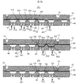
- FIG. 1 shows a state in which the analysis chip 10 is mounted on the sample processing apparatus of FIG. 2 and the drive unit 40 is pressed by the lid 30 through the membrane 20.
- FIG. 1A is a view from the upper surface side of the analysis chip 10. The well as the container on the upper surface side of the analysis chip is indicated by a solid line, and the groove on the lower surface side of the analysis chip and the recess of the drive unit 40 are indicated by a broken line .
- 1B is an AA cross section in FIG. 1A
- FIG. 1C is a BB cross section in FIG. 1A, and the analysis chip 10 and the drive unit 40 are in contact via the membrane 20. ing.
- a sample well 11 as a container, an air intake well 12, a sample waste well 13, a stirring well 14, a reagent well 15, and a mixed solution waste well 16 as a well.
- the lower surface side, the plurality of grooves 111, 112, 113, 114, 115, 121, 122, 123, 124, 131, 132, 133, 141, 142, 143, 144, 145, 151, 152, 153, 154 161, 162, 163, 164 and 165 are provided.
- the membrane 20 is an elastic body made of a polymer compound such as rubber or resin, and moves fluid by deforming with air pressure, and seals the fluid by adhering to the surfaces of the analysis chip 10 and the drive unit 40 respectively. doing.
- the drive unit 40 is provided with recesses 41, 42, 43, 44, 45, 46, 47, 48, 49, 4A, 4C, 4D, 4E, 4F on the upper surface side in close contact with the membrane 20; Tubes of different kinds, ie pressure pipes 411, 421, 431, 441, 451, 461, 471, 481, 4A1, 4B1, 4C1, 4D1, 4E1, 4F1 and decompression pipes 412, 422, 432, 442, 452, Each of 462, 472, 482, 492, 4A2, 4B2, 4C2, 4D2, 4E2, 4F2 is connected to the air piping 70 shown in FIG.
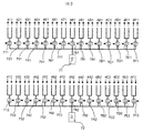
- FIG. 3 is an air piping system diagram for controlling the pressure of the drive unit 40 of the present embodiment, which is installed in the control unit 60.
- the pressure pump 71 is branched into 15 systems, and the pressure solenoid valves 711, 721, 731, 741, 751, 761, 771, 781, 791, 7A1, 7B1, 7C1, 7D1, 7E1 and 7F1 are further divided into two systems. It branches and is connected to the pressure pipe of the drive unit 40.
- the reason why the pressurizing solenoid valve is branched into two systems is that the sample processing apparatus of the present embodiment is equipped with two analysis chips as shown in FIG. 2A.
- the pressure reducing pump 72 is branched into 15 systems, and the pressure reducing electromagnetic valves 712, 722, 732, 742, 752, 762, 772, 782, 792, 7A2, 7B2, 7C2, 7D2, 7E2, 7F2 are further added. It branches into two systems and is connected to the pressure reducing tube of the drive unit 40.
- the air piping from the pump 71 to the drive unit 40 is communicated at the time of energization, and the groove 41 and the like of the drive unit 40 is pressurized.
- the air piping on the pump 71 side is closed, and the air piping on the driving unit 40 side can flow out to the outside, that is, to the atmosphere side, and does not flow into the air piping from the outside.
- the air piping from the pump 72 to the drive unit 40 is communicated with the pressure reducing solenoid valve 712 and the like at the time of energization, and the groove 41 and the like of the drive unit 40 is decompressed.
- the air pipe on the pump 72 side is closed, and the air can flow from the air side to the air pipe on the drive unit 40 side, and does not flow out from the air pipe.
- the drive unit 40 is installed in the sample processing apparatus, and the air piping 70 is connected.
- the operator attaches the analysis chip 10 and the membrane 20 to the drive unit 40, and closes the lid 30.
- This state is shown in FIG.
- the analysis chip 10 and the membrane 20 are usually packaged integrally, and the packaged one is attached to the drive unit 40.
- the operator selects a control procedure corresponding to the analysis content from the operation unit 61 and starts the apparatus operation.
- the sample processing apparatus starts the initialization operation 203, and performs the opening / closing operation of the solenoid valve, the pressurization and depressurization operations by the pump, and the pressure check as needed.
- the operator inserts the sample into the sample well 11 through the sample insertion window 32 in the loading operation 205, and similarly inserts the reagent into the reagent well 15 through the reagent insertion window 33.
- the pressurizing solenoid valves 711 and 7F1 are open, the recesses 41 and 4F are pressurized, and the membrane 20 is pressed against the lower surface of the analysis chip by both grooves, so the grooves 111 and 151 are sealed, The sample and the reagent do not flow out from the sample well 11 and the reagent well 15, respectively.
- the operator issues an instruction to start the analysis operation 206 from the operation unit 61, and the sample processing apparatus carries out the analysis operation 207.
- the analysis result is stored in the memory in the sample processing apparatus, and displayed on the display of the operation unit 61 as needed.
- the operator removes the analysis chip 10 and the membrane 20 and stores or discards. If there is the next analysis, it returns to the analysis chip mounting 201, mounts a new analysis chip, and carries out the analysis. If there is no analysis, the operator performs an end operation 209 at the operation unit 61 and stops the apparatus.
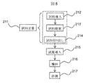
- the sample held in the sample well 11 is introduced to the determination groove 115 by feeding the sample to the sample disposal well 13.
- air is introduced from the air intake well 12 and the excess sample is discarded into the sample discarding well 13.
- sample cutout 214 air is introduced from the air intake well 12, and the sample held in the determination groove 115 is cut out into the stirring well 14.
- a series of operations of the sample introduction 212, the sample waste 213, and the sample cutout 214 described above is a sample quantification 211 for quantifying a sample.
- FIG. 6 is a view showing the flow of the sample introduction operation by open / close control of the pressure application solenoid valve and the pressure release solenoid valve of the sample processing apparatus of the present embodiment
- FIG. 7ab is an explanatory view of the sample introduction operation
- the solenoid valve is closed in places where there is no solid arrow, a broken arrow is used to explain that the solenoid valve is particularly closed in the description of the figures in the reference. That is, the upward broken arrow indicates that the pressurizing solenoid valve has switched from open to closed, and the downward dashed arrow indicates that the depressurizing solenoid valve has switched from opening to close.
- the sample 80 is held in the sample well 11 in the state at the start of the above-mentioned analysis operation. That is, in (A) of FIG. 7A, since the sample sealing dent pressurizing solenoid valve 711 is open, air flows from the sample sealing dent pressurizing tube 411 and the sample sealing dent 41 is pressurized, The sample sealing recess pressure reducing solenoid valve 712 on the side of the sample sealing recess pressure reducing tube 412 is closed. Although not shown, the reagent is held in the reagent well 15, and the reagent sealing recess 4F is similarly pressurized because the reagent sealing recess pressing solenoid valve 7F1 is open.
- a sample sealing portion gap 413 is generated between the membrane 20 and the analysis chip 10, and the sample 80 is upstream from the sample well 11 for sample sealing. It is drawn into the sample sealing gap 413 through the groove 111.
- the sample introduction dent pressurization solenoid valve 731 and the sample introduction dent pressure reduction solenoid valve 722 are opened while sealing the sample.
- the depression depressurizing solenoid valve 712 By closing the depression depressurizing solenoid valve 712, the flow of air from the sample sealing dent depressurization tube 412 is stopped, and by opening the sample seal dent pressurizing solenoid valve 711 from the sample sealing dent depressurizing tube 411. Air is introduced to press the sample sealing recess 41.
- the sample flow upstream groove 112 and the sample introduction upstream groove 113 are sealed, and the sample 80 is held in the sample flow portion gap 423.
- air is made to flow from the stirring inlet dent pressurizing pipe 451 by opening the stirring inlet dent pressurizing solenoid valve 751, to pressurize the stirring inlet dent 45, and air is opened by opening the air flow dent pressurizing solenoid valve 7A1. Air is allowed to flow in from the flow dent pressure pipe 4A1, pressurize the air flow dent 4A, and open the sample discharge dent pressure reduction solenoid valve 7C2 to cause air to flow out from the sample discharge dent pressure reduction pipe 4C2, and sample discharge dent 4C.
- the air branch groove 124 is on the upstream side
- the air flow recess 4A between a certain air intake well 12 is pressurized, and the membrane 20 is pressed against the lower surface side of the analysis chip 10 and sealed, and similarly, the sample branch groove 143 is also downstream thereof
- a stirring inlet recess 45 located between a certain stirring well 14 is pressurized, and the membrane 20 is pressed against the lower surface side of the analysis chip 10 and sealed.
- the sample discharge upstream groove 133 has two depressions between it and the sample waste well 13 on the downstream side, that is, the sample discharge dent 4C and the sample waste dent 4D are both decompressed, and the membrane 20 is each dent
- the gap is generated between the lower surface of the analysis chip 10 and the membrane 20, and the sample discharge upstream groove 133 and the sample discarding well 13 communicate with each other.
- closing the sample introduction dent pressurization solenoid valve 731 stops the flow of air from the sample introduction dent pressurization tube 431 and closing the sample flow dent depression depressurization solenoid valve 72, the sample flow dent Outflow of air from the pressure reducing pipe 422 is stopped.
- the membrane 20 of the sample flow recess 42 tries to return to the original state by elastic force, and tries to push the sample 80 out of the sample flow portion gap 423.
- the sample flow upstream groove 112 is sealed by the pressurization of the sample sealing recess 41, it can not flow out.
- the sample 80 intrudes into the sample introduction gap 433 between the membrane 20 of the sample introduction recess 43 and the analysis chip 10 through the sample introduction upstream groove 113 from the sample flow portion gap 423 and from the sample introduction downstream groove 114 It is introduced into the determination groove 115, and from the sample discharge upstream groove 133, the sample discharge portion gap 4C3 between the membrane 20 of the sample discharge recess 4C and the analysis chip 10, the sample discharge downstream groove 132, the sample waste recess 4D membrane 20 Through the sample waste portion gap 4D3 between the sample and the analysis chip 10, and the sample waste downstream groove 131, it flows out to the sample waste well 13.
- sample flow recess 42 is pressurized by opening the sample flow recess pressing pipe 721, and the sample 80 is completely pushed out by pressing the membrane against the analysis chip 10.
- the solenoid valve 7A1 for air introduction depression and pressurization is open while the solenoid valve 7C2 for sample discharge depression and pressure reduction and the specimen waste dent
- the pressure reducing solenoid valve 7D2 By closing the pressure reducing solenoid valve 7D2, the outflow of air from the sample discharge recess 4C and the sample waste recess 4D is stopped.
- the sample flow indentation and pressurization solenoid valve 721 and the stirring inlet indentation pressurization solenoid valve 751 remain open. By doing this, the membrane returns to the lower surface side of the analysis chip 10 by the elastic force in the sample discharge portion gap 4C3 and the sample waste portion gap 4D3, and pushes the sample 80 into the sample waste well 13.
- sample 80 is filled in the determination groove 115.
- Sample 80 is also used for sample sealing upstream groove 111, sample flow upstream groove 112, sample introduction upstream groove 113, sample introduction downstream groove 114, sample discharge upstream groove 133, sample discharge downstream groove 132, and sample waste downstream groove 131 Although it is filled, it does not enter the air branch groove 124 and the groove on the upstream side of the air intake well 12 and the sample branch groove 143 and the groove on the downstream of the stirring well 14 side thereof.
- the recess closest to the determination groove 115 that is, the sample introduction recess 43, the cutout recess 44, the air.
- the introduction dent 4B and the sample discharge dent 4C are not pressurized. This is because pressing the recess closest to the metering groove 115 pushes up the membrane in the metering groove 115, which may reduce the volume and affect the quantitativeness. For example, in FIG.
- FIG. 9 is a view showing a flow of sample discarding operation by open / close control of the pressurizing solenoid valve and the depressurizing solenoid valve of the sample processing apparatus of the present embodiment, and FIG.
- the air flow dent depressurization solenoid valve 7A2 is opened, and the air sealing dent depressurization solenoid valve 792 is closed.
- the air sealing recess pressure reducing tube 492 By stopping the outflow of air from the air sealing recess pressure reducing tube 492 and opening the air sealing recess pressure applying solenoid valve 791, air is made to flow in from the air sealing recess pressure tube 491, and the air sealing recess 49 is formed. Pressurize.
- the air flow upstream groove 122 is sealed, and the air is held in the air flow portion gap 4A3.
- the sample flow recess 42 and the stirring inlet recess 45 are pressurized with the sample flow recess pressing solenoid valve 721 and the stirring inlet recess pressing solenoid valve 751 open.
- the membrane 20 tries to push out the air in the air flow portion gap 4A3.
- the air sealing recess 49, the sample flow recess 42 and the stirring inlet recess 45 are pressurized, air in the air flowing portion gap 4A3 moves toward the air sealing upstream groove 122 and the metering groove 115.
- the gap between the membrane 20 and the analysis chip 10 of the non-pressurized sample discharge recess 4C from the sample discharge upstream groove 133, the sample discharge downstream groove 132, the non-pressurized sample waste recess 4D membrane moves to the sample waste downstream groove 131 and pushes the sample to the sample waste well 13.
- the sample waste 213 in FIG. 5, that is, the sample discharge upstream groove 133, the sample discharge downstream groove 132, and the sample in the sample waste downstream groove 131 downstream of the determination groove 115 are discharged to the sample waste well 13 It is an operation.
- FIG. 11 is a view showing a flow of a sample cutting operation by open / close control of the pressurizing solenoid valve and the depressurizing solenoid valve of the sample processing apparatus of the present embodiment, and FIG.
- FIG. 11 and (A) (cross section BB) of FIG. 12 a are the subsequent operations from (D) of FIG. 9 and (D) of FIG. Except that the operations from (A) to (C) are exactly the same. That is, in (A), with the air flow dent pressurizing solenoid valve 7A1 open, the air seal dent pressurizing solenoid valve 791 is closed and the air seal dent depressurizing solenoid valve 792 is opened, so that the air seal dent 49 is closed. The pressure is reduced and air is drawn into the air seal gap 493.
- the air flow dent pressurizing solenoid valve 7A1 is closed and the air flow dent depressurizing solenoid valve 7A2 is opened to depressurize the air flow dent 4A and draw air into the air flow portion gap 4A3.
- the air sealing recess pressure reducing solenoid valve 792 is closed and the air sealing recess pressurizing solenoid valve 791 is opened to seal the air sealing recess 49 by pressurizing, and the air flowing portion gap 4A3. Hold the air on.
- stirring is performed by opening the solenoid valve 761 for pressing the stirring outlet recess and the solenoid valve 7D1 for pressing the sample disposal recess.
- the outlet recess 46 and the sample waste recess 4D are pressurized and sealed.
- the sample flow recess pressurizing solenoid valve 721 is also opened, and the sample flow recess 42 is also pressurized and sealed.
- the sample flow recess 42 is sealed, the sample can not move to the sample introduction downstream groove 114 side, and the membrane 20 of the cut-out recess 44 which is not pressurized is analyzed from the sample branch groove 143
- the gap between the chip 10 and the cutout downstream groove 142, the gap between the membrane 20 of the stirring inlet recess 45 not pressurized and the analysis chip 10, and the stirring inlet downstream groove 141 are moved to the stirring well 14 It is pushed out.
- the sample disposal 213 is performed after the sample introduction 212 and the sample cutout 214 is performed, but the operation of the sample disposal 213 can be omitted, and the sample cutout 214 is performed following the sample introduction 212 You may
- reagent introduction 215 is performed. This operation moves the reagent in the reagent well 15 to the stirring well 14 in FIG. 1 and is the same operation as the sample introduction 212. Therefore, the operation flow of the reagent introduction by the solenoid valve control is shown in FIG. The operation will be described with reference to the symbols of FIG. 1 and FIG.
- (A) of FIG. 13 is in the initial state, the reagent sealing dent pressurizing / pressing solenoid valve 7F1 is opened, and the reagent sealing dent 4F is pressurized and sealed, and the reagent in the reagent well 15 flows out do not do.
- the reagent sealing recess 4F is depressurized by closing the reagent sealing recess pressurizing solenoid valve 7F1 and opening the reagent sealing recess depressurizing solenoid valve 7F2, and the membrane 20 and the lower surface of the analysis chip 10
- the reagent is drawn from the reagent well 15 into the gap generated between them.
- the reagent flow recess 4E is depressurized by opening the reagent flow recess depressurization solenoid valve 7E2, and the reagent is further drawn into the gap generated between the membrane 20 and the lower surface of the analysis chip 10.
- the detection section introduction recess and pressurization solenoid valve 771 is opened to pressurize and seal the detection section introduction recess 47, and the reagent seal recess depression pressure reduction solenoid valve 7F2 is closed to seal the reagent seal.
- the air sealing recess 4F is sealed by pressing it by opening the stop recess pressurizing solenoid valve 7F1.
- the reagent can not move to the detection portion introduction upstream groove 165 side, and the membrane 20 and the analysis of the stirring exit recess 46 which is not pressurized from the stirring outlet downstream groove 145 The gap between the tip 10 and the stirring outlet upstream groove 144 is moved to the stirring well 14 and pushed out.
- the above is the reagent introduction 215 of FIG. 5, that is, the operation of moving the reagent in the reagent well 15 to the stirring well 14.
- the sample is determined by the sample determination 211 and the reagent is held in the stirring well 14 by the reagent introduction 215. Since the sample and the reagent may be held in the stirring well 14, the reagent quantitative determination 211 may be performed after the reagent introduction 215.
- the sample is quantified by the volume of the metering groove, while the reagent is quantified by the volume of the reagent flow recess 4E, more precisely the volume minus the thickness of the membrane 20.
- the reagent is quantified by the amount injected into the reagent well 15. That is, in the case of quantifying with the reagent flow recess 4E, a predetermined amount of liquid is transferred to the stirring well 14 by injecting a reagent larger than the amount of liquid to be quantified into the reagent well 15 and performing the reagent introduction 215 operation. It can move.
- an amount smaller than the volume of the reagent flow recess 4E may be injected into the reagent well 15.
- the operation of the reagent introduction 215 may be performed multiple times.
- the fluid is made to flow by deforming the membrane 20, if the amount of deformation is too small, it becomes difficult to obtain quantitative performance. Therefore, when quantifying a small amount of liquid, it is necessary to make the reagent flow dent smaller and reduce the deformation amount of the membrane 20 in the reagent introduction 215, but the method of the determination groove 115 used in the sample determination 211 is the sample It is not necessary to make the flow recess 42 small, but it is suitable for the determination of a small amount of liquid. Therefore, which of the sample quantification 211 and the reagent introduction 215 is used depends on the specification of the liquid volume and the quantitative reproducibility.
- the determination groove 115 was used for the determination of the sample, and the volume of the reagent flow recess was used for the determination of the reagent.
- the determination groove is also used for the determination of the reagent, that is, two for sample and for the reagent It is conceivable to use a quantitative groove or a single quantitative groove in order.
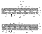
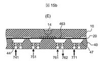
- FIG. 14 is a view showing a flow of stirring operation by open / close control of the pressurizing solenoid valve and the depressurizing solenoid valve of the sample processing apparatus of this embodiment
- FIG. 15ab is an explanatory view of the stirring operation.
- FIG. 16 is a diagram showing a flow of measurement operation by opening and closing control of the pressurizing solenoid valve and the depressurizing solenoid valve of the sample processing apparatus of the present embodiment.
- the stirring outlet recess 46 is depressurized by opening the stirring outlet recess depressurizing solenoid valve 762, and the mixed solution held in the stirring well 14 after the stirring is completed from the stirring outlet upstream groove 144. Suction.
- the detection introduction portion dent depression pressure reduction solenoid valve 772 is opened to depressurize the detection portion introduction dent 47, and the mixed solution is sucked from the stirring outlet downstream groove 145 and the detection portion upstream groove. .
- the reagent flow dent 4E is pressurized and sealed by opening the reagent flow dent pressing solenoid valve 7E1, and the stirring outlet dent pressure reducing solenoid valve 762 is closed, and the stirring outlet dent
- the stirring outlet recess 46 is pressurized by opening the pressurizing solenoid valve 761.
- the detection section introduction dent and the solenoid valve 772 for pressure reduction are closed.
- the membrane 20 of the detection portion introduction recess 47 tries to return to the lower surface side of the analysis chip 10 by elastic force, and pushes out the mixed solution. Since the stirring outlet recess 46 and the reagent flow recess 4E are sealed, the mixture is not pressurized while the mixture fills the detection portion downstream groove 164, the detection groove 163, and the mixture drain upstream groove 162.
- the gap between the membrane 20 and the analysis chip 10 of the liquid waste recess 48 moves to the mixed liquid waste downstream groove 161, and the excess liquid mixture is pushed out to the mixed liquid waste well 16.
- observation light is irradiated to the detection groove 163 from the observation window 34 of FIG. 2 to acquire data.
- the above is the operation of the measurement 217 of FIG. 5, and this completes the analysis operation 207 of FIG.
- the detection groove 163 has a function of holding the liquid in a sealed space, and in the first embodiment described above, the analysis light is emitted by irradiating observation light to the detection groove 164 from the observation window 34 and acquiring data.
- the processing in the processing groove of this embodiment is not limited to analysis and detection.
- the reaction may be performed by holding in the detection groove 163 and then recovering from the mixed solution discarding well 16 or holding the liquid in the detection groove 163 Processing other than optical measurement, such as temperature control, may be performed.
- the fluid and gas are allowed to flow by deforming the membrane 20 by air pressure, and after one end of the liquid is held in the measurement groove 115, the liquid in the measurement groove 115 is expelled with air to quantify a certain amount of liquid.
- the volume of the metering groove it becomes possible to perform a predetermined amount of metering operation without changing the shapes of the other grooves and recesses or the control operation of the solenoid valve switching.
- the fluid when the pressure of the recess is controlled to deform the membrane to move the fluid, the fluid can be moved if there are three recesses. That is, in the introduction of the reagent, the liquid can be fed by three recesses of the reagent sealing recess 4 F, the reagent flow recess 4 E, and the stirring outlet recess 46.
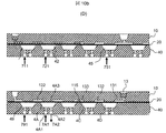
- FIG. 17 shows a sample processing apparatus that realizes quantification using three recesses.
- the difference from FIG. 1 is that the four recesses closest to the determination groove 115 shown in FIG. 1, the sample seal recess 41, the sample flow recess 42, the sample introduction recess 43, the sample discharge recess 4C, and the sample waste recess 4D
- the quantification groove 115 is provided not on the lower surface side of the analysis chip 10, that is, on the upper surface side but not on the side in contact with the membrane 20.
- the sample quantification 211 in FIG. 5 is the same as in FIG. 6 to FIG. 12 ab described in the first embodiment, except for the control operation for the four concave portions closest to the quantification groove 115.
- the concave portion closest to the determination groove 815 is pressed, but since the determination groove 815 is not in contact with the membrane 20, it is affected by the volume change due to the deformation of the membrane. There is no loss of quantitativeness.
- the sample held in the sample well 11 is introduced into the determination groove 115 by transferring the sample to the sample disposal well 13, and the sample introduced into the determination groove 115 is transferred to the stirring well 14.
- the samples are quantified by cutting them out.
- each groove from the sample well 11 to the determination groove 115 that is, the sample sealing upstream groove 111, the sample flow upstream groove 112, the sample introduction upstream groove 113, Air is present in the sample introduction downstream groove 114, and when the sample is introduced, each air passes through the determination groove 115 and is discharged to the sample discarding well 13. That is, as shown in FIG. 7A (B), when drawing the sample 80 from the sample well 11 through the sample sealing upstream groove 111 to the sample sealing portion gap 413, the air present in the sample sealing upstream groove 111 Is drawn to the downstream end (right side of the figure) of the sample sealing portion gap 413, and in FIG.
- each gap such as the sample sealing portion gap 413
- the position of the sample and air may be reversed or the air may be split when drawing the sample. If the positions of the sample and the air are reversed, air may flow into the determination groove 115 after the sample is discharged into the sample discarding well 13 and the quantitativity may be lost.
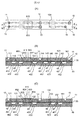
- FIG. 18 shows an analysis chip provided with an air removal mechanism.
- the same reference numerals as in FIG. 1 denote the same components.
- FIG. 18 is a view from the upper surface side of the analysis chip 10, and (B), (C) and (D) of FIG. 1 are respectively taken on the AA, BB and CC cross sections of FIG. is there.
- Each cross-sectional view is a cross-sectional view of a portion related to the quantitative operation.
- FIG. 18 the mechanism necessary for air removal is added or modified as compared with FIG. 1, and the addition and modification are described in the following description of the operation.
- the air removal operation is an operation performed immediately before the sample quantification 211 in FIG. 5, and the operation flow in FIG. 4 is the same.
- the pressurizing solenoid valve 711 is opened to press the recess 41, although the groove 111 is sealed so that the sample does not flow out of the sample well 11, in the present embodiment, as shown in FIG. 18B, the sample holding vertical hole 845 located immediately below the sample well 11.
- both the sample sealing recess 41 and the vertical hole air introduction recess 4G are pressurized.
- the membrane 20 is drawn by depressurizing the vertical air introduction recess 4G, and air in the sample holding vertical hole 845 and a sample well are formed in the gap generated between the membrane 20 and the analysis chip 10 on the upper side of the vertical air introduction dent 4G.
- the sample in 11 is pulled in.
- air and a sample are drawn into the gap generated between the membrane 20 and the analysis chip 10 above the vertical air flow recess 4 H by reducing the pressure of the vertical air flow recess 4 H.
- the vertical hole air introduction recess 4G is pressurized while pressurizing the vertical hole air discharge recess 4J, thereby closing the gap at the upper part of the vertical hole air introduction recess 4G and returning the sample to the sample well 11.
- the pressurization of the vertical air discharge recess 4J is stopped, and the pressure reduction of the vertical air flow recess 4H is stopped or pressurized to discharge the sample to the sample disposal well 13.
- the air of the sample holding well 845 is exhausted to the sample discarding well 13 and the sample holding well 845 is filled with the sample.
- the sample held in the sample well 11 is introduced to the determination groove 115 by transferring the solution to the sample disposal well 13.
- this operation is performed as follows.
- the sample sealing recess 41 by depressurizing the sample sealing recess 41, the sample is drawn into the gap generated between the membrane 20 and the analysis chip 10 above the sample sealing recess 41.
- the sample flow recess 4 K by depressurizing the sample flow recess 4 K, the sample is drawn into the gap generated between the membrane 20 and the analysis chip 10 above the sample flow recess 4 K.
- the air in the sample sealing downstream groove 181 and the sample flow groove 182 since the air in the sample sealing downstream groove 181 and the sample flow groove 182 has already been removed, the air does not enter the gap.
- pressing the sample sealing recess 41 while pressurizing the groove air discharge recess 4L and the sample introduction recess 43 the gap above the sample sealing recess 41 is closed and the sample is returned to the sample well 11.
- the pressurization of the sample introduction recess 43 is stopped, and while the sample discharge recess 4C and the sample waste recess 4D are decompressed, the sample flow recess 4K is stopped or pressurized to introduce the sample into the determination groove 115, and the sample is discarded. Eject into well 13 By this operation, the sample is filled in the sample introduction downstream groove 114, the determination groove 115, the sample discharge upstream groove 133, and the like.
- the air in the sample discharge upstream groove 133 is discharged to the sample waste well 13 by sucking air from the air intake well 12 and sending it to the sample waste well 13.
- the air is drawn from the air intake well 12 and sent to the stirring well 14 so that the sample of the measurement groove 115 is discharged to the stirring well 14.
- Example 1 The difference from Example 1 is that the channel system for the air intake well 12, the air sealing recess 49, the air flow recess 4A, the air introduction recess 4B, the sample discard well 13, the sample waste recess 4D, the sample discharge recess This is a change for using the sample waste well 13 for the exhaust of air in the air removal operation, in that the 4C flow path system is changed to the opposite position to the metering groove 115 It is.
- each operation of reagent introduction 215, stirring 216, and measurement 217 is executed, but the arrangement of the flow path system related to these operations (FIG. 18) is the first embodiment (FIG. 1). And the operation is exactly the same.
- the air of the sample holding vertical hole 845 and the air of the sample sealing downstream groove 181 and the sample flow groove 182 are removed. That is, the sample well 11 and the sample holding vertical hole 845 immediately below it are disposed on the top of the sample sealing recess 41, one end of the vertical hole air introducing groove 171 is connected to the sample holding vertical hole 845, and the other end is the vertical hole air introducing dent 4G.
- the air in the sample holding vertical hole 845 is removed by depressurizing the vertical hole air introduction recess 4G, and the sample holding vertical hole 845 is filled with the sample. Therefore, air is not drawn in even if the sample sealing recess 41 is depressurized in the next operation.
- one end of the sample sealing downstream groove 181 is disposed above the sample sealing recess 41, and the other end is disposed above the sample introducing recess 43, and one end of the sample flow groove 182 is disposed above the sample flow recess 4K.
- the air is removed from the sample sealing downstream groove 181 and the sample flowing groove 182 by reducing the pressure of the sample flow recess 4K by aligning the end of the sample sealing downstream groove 181 disposed at the top of the sample introduction recess 43.
- the sealing downstream groove 181 and the sample flow groove 182 are filled with the sample. Therefore, even if the sample is introduced into the determination groove 115 in the next operation, air is not mixed.
- the cross-sectional area is small and the change in cross-sectional area is also small, so the positions of the air in the groove and the sample are not reversed. If there is no air upstream of the groove 114, the air in the sample introduction downstream groove 114 and the metering groove 115 is pushed out, and no air remains in the metering groove 115.
Landscapes
- Chemical & Material Sciences (AREA)
- Health & Medical Sciences (AREA)
- Analytical Chemistry (AREA)
- General Health & Medical Sciences (AREA)
- Immunology (AREA)
- Biochemistry (AREA)
- Life Sciences & Earth Sciences (AREA)
- General Physics & Mathematics (AREA)
- Physics & Mathematics (AREA)
- Pathology (AREA)
- Hematology (AREA)
- Dispersion Chemistry (AREA)
- Clinical Laboratory Science (AREA)
- Chemical Kinetics & Catalysis (AREA)
- Computer Hardware Design (AREA)
- Microelectronics & Electronic Packaging (AREA)
- Engineering & Computer Science (AREA)
- Automatic Analysis And Handling Materials Therefor (AREA)
- Micromachines (AREA)
Priority Applications (5)
| Application Number | Priority Date | Filing Date | Title |
|---|---|---|---|
| CN201880032745.2A CN110637233A (zh) | 2017-06-26 | 2018-05-11 | 样品处理装置 |
| DE112018001977.2T DE112018001977T5 (de) | 2017-06-26 | 2018-05-11 | Probenbehandlungsvorrichtung |
| GB1915791.6A GB2577406B (en) | 2017-06-26 | 2018-05-11 | Sample processing device |
| US16/609,248 US20200047181A1 (en) | 2017-06-26 | 2018-05-11 | Sample Processing Device |
| SG11201910270XA SG11201910270XA (en) | 2017-06-26 | 2018-05-11 | Sample processing device |
Applications Claiming Priority (2)
| Application Number | Priority Date | Filing Date | Title |
|---|---|---|---|
| JP2017123833A JP6789889B2 (ja) | 2017-06-26 | 2017-06-26 | 試料処理装置 |
| JP2017-123833 | 2017-06-26 |
Publications (1)
| Publication Number | Publication Date |
|---|---|
| WO2019003659A1 true WO2019003659A1 (ja) | 2019-01-03 |
Family
ID=64740544
Family Applications (1)
| Application Number | Title | Priority Date | Filing Date |
|---|---|---|---|
| PCT/JP2018/018259 Ceased WO2019003659A1 (ja) | 2017-06-26 | 2018-05-11 | 試料処理装置 |
Country Status (7)
| Country | Link |
|---|---|
| US (1) | US20200047181A1 (https=) |
| JP (1) | JP6789889B2 (https=) |
| CN (1) | CN110637233A (https=) |
| DE (1) | DE112018001977T5 (https=) |
| GB (1) | GB2577406B (https=) |
| SG (1) | SG11201910270XA (https=) |
| WO (1) | WO2019003659A1 (https=) |
Families Citing this family (2)
| Publication number | Priority date | Publication date | Assignee | Title |
|---|---|---|---|---|
| US20240299935A1 (en) * | 2023-03-06 | 2024-09-12 | Fluidion US Inc. | Reagent Delivery System for Microfluidic Chemical Analyzer |
| CN115970781B (zh) * | 2023-03-21 | 2024-01-12 | 杭州霆科生物科技有限公司 | 一种定量加样结构及其浓度梯度微流控芯片和控制方法 |
Citations (4)
| Publication number | Priority date | Publication date | Assignee | Title |
|---|---|---|---|---|
| WO2014017219A1 (ja) * | 2012-07-23 | 2014-01-30 | 株式会社日立ハイテクノロジーズ | 生化学用カートリッジ及び生化学処理装置 |
| WO2014119497A1 (ja) * | 2013-01-31 | 2014-08-07 | 株式会社 日立ハイテクノロジーズ | 生化学用カートリッジ、生化学用カートリッジ及びカートリッジホルダのセット |
| JP2014180627A (ja) * | 2013-03-19 | 2014-09-29 | Hitachi High-Technologies Corp | 送液デバイスおよびそれを用いた化学分析装置 |
| US20160250636A1 (en) * | 2013-10-07 | 2016-09-01 | M2P-Labs Gmbh | Microreactor system |
Family Cites Families (2)
| Publication number | Priority date | Publication date | Assignee | Title |
|---|---|---|---|---|
| US20110315227A1 (en) | 2008-12-24 | 2011-12-29 | Wenmiao Shu | Microfluidic system and method |
| JP2011030522A (ja) * | 2009-08-04 | 2011-02-17 | Aida Engineering Ltd | マイクロ流体デバイス |
-
2017
- 2017-06-26 JP JP2017123833A patent/JP6789889B2/ja active Active
-
2018
- 2018-05-11 SG SG11201910270XA patent/SG11201910270XA/en unknown
- 2018-05-11 CN CN201880032745.2A patent/CN110637233A/zh active Pending
- 2018-05-11 GB GB1915791.6A patent/GB2577406B/en active Active
- 2018-05-11 DE DE112018001977.2T patent/DE112018001977T5/de not_active Ceased
- 2018-05-11 WO PCT/JP2018/018259 patent/WO2019003659A1/ja not_active Ceased
- 2018-05-11 US US16/609,248 patent/US20200047181A1/en not_active Abandoned
Patent Citations (4)
| Publication number | Priority date | Publication date | Assignee | Title |
|---|---|---|---|---|
| WO2014017219A1 (ja) * | 2012-07-23 | 2014-01-30 | 株式会社日立ハイテクノロジーズ | 生化学用カートリッジ及び生化学処理装置 |
| WO2014119497A1 (ja) * | 2013-01-31 | 2014-08-07 | 株式会社 日立ハイテクノロジーズ | 生化学用カートリッジ、生化学用カートリッジ及びカートリッジホルダのセット |
| JP2014180627A (ja) * | 2013-03-19 | 2014-09-29 | Hitachi High-Technologies Corp | 送液デバイスおよびそれを用いた化学分析装置 |
| US20160250636A1 (en) * | 2013-10-07 | 2016-09-01 | M2P-Labs Gmbh | Microreactor system |
Also Published As
| Publication number | Publication date |
|---|---|
| GB2577406B (en) | 2022-03-30 |
| GB2577406A (en) | 2020-03-25 |
| SG11201910270XA (en) | 2020-01-30 |
| US20200047181A1 (en) | 2020-02-13 |
| JP2019007841A (ja) | 2019-01-17 |
| JP6789889B2 (ja) | 2020-11-25 |
| DE112018001977T5 (de) | 2019-12-24 |
| GB201915791D0 (en) | 2019-12-18 |
| CN110637233A (zh) | 2019-12-31 |
Similar Documents
| Publication | Publication Date | Title |
|---|---|---|
| EP2653865B1 (en) | Microfluidic separation of plasma for colormetric assay | |
| CN100534619C (zh) | 对可通过导管进入测量室中的液态测量样品进行电化学测量的方法和相应的布置 | |
| CN101529243B (zh) | 用于在自动分析仪中吸出和分配液体的装置 | |
| WO2018020924A1 (ja) | 気泡除去構造、気泡除去方法、及び攪拌方法 | |
| WO2009119698A1 (ja) | マイクロチップの流路制御機構 | |
| WO2014017219A1 (ja) | 生化学用カートリッジ及び生化学処理装置 | |
| US10246675B2 (en) | Biochemical cartridge, and biochemical cartridge and cartridge holder set | |
| JP4593451B2 (ja) | マイクロリアクターシステム及び送液方法 | |
| WO2019003659A1 (ja) | 試料処理装置 | |
| JP5440820B2 (ja) | マイクロチップの流体制御機構及び流体制御方法 | |
| JP4551123B2 (ja) | マイクロ流体システム及びそれを用いる処理方法 | |
| JP2010065584A (ja) | 送液ポンプ及び該ポンプによる送液方法 | |
| JP3967331B2 (ja) | 液体混合方法、液体混合装置およびマイクロチップ | |
| JP7455827B2 (ja) | 高い再現性を提供するマイクロ流体サンプル調製デバイス | |
| CN112424610B (zh) | 试样处理设备以及装置 | |
| WO2019146631A1 (ja) | 試料処理装置 | |
| KR20100056291A (ko) | 착탈식 유체배관부를 가진 순차주입분석 장치 | |
| KR20000016634A (ko) | 분석용 카드에 액체 매질을 충전하는 방법 및 장치 | |
| JPH10339267A (ja) | 送液機構、並びに該送液機構を用いたサンプリング機構及びカラムクロマトグラフ装置 | |
| CN220590057U (zh) | 一种基于滤纸的混合微流体平台 | |
| CN121443390A (zh) | 流体运输装置、流体运输方法及生化物质分析设备 | |
| JP2016176718A (ja) | 試薬カートリッジ | |
| JP2002250737A (ja) | ビーズと微量液体の位置制御機構 |
Legal Events
| Date | Code | Title | Description |
|---|---|---|---|
| 121 | Ep: the epo has been informed by wipo that ep was designated in this application |
Ref document number: 18822820 Country of ref document: EP Kind code of ref document: A1 |
|
| ENP | Entry into the national phase |
Ref document number: 201915791 Country of ref document: GB Kind code of ref document: A Free format text: PCT FILING DATE = 20180511 |
|
| 122 | Ep: pct application non-entry in european phase |
Ref document number: 18822820 Country of ref document: EP Kind code of ref document: A1 |