WO2019003552A1 - モータの製造方法、センサマグネット部の位置決め装置、モータ、及びモータ製造装置 - Google Patents
モータの製造方法、センサマグネット部の位置決め装置、モータ、及びモータ製造装置 Download PDFInfo
- Publication number
- WO2019003552A1 WO2019003552A1 PCT/JP2018/014545 JP2018014545W WO2019003552A1 WO 2019003552 A1 WO2019003552 A1 WO 2019003552A1 JP 2018014545 W JP2018014545 W JP 2018014545W WO 2019003552 A1 WO2019003552 A1 WO 2019003552A1
- Authority
- WO
- WIPO (PCT)
- Prior art keywords
- unit
- positioning
- sensor magnet
- shaft
- magnet
- Prior art date
- Legal status (The legal status is an assumption and is not a legal conclusion. Google has not performed a legal analysis and makes no representation as to the accuracy of the status listed.)
- Ceased
Links
Images











Classifications
-
- H—ELECTRICITY
- H02—GENERATION; CONVERSION OR DISTRIBUTION OF ELECTRIC POWER
- H02K—DYNAMO-ELECTRIC MACHINES
- H02K11/00—Structural association of dynamo-electric machines with electric components or with devices for shielding, monitoring or protection
- H02K11/20—Structural association of dynamo-electric machines with electric components or with devices for shielding, monitoring or protection for measuring, monitoring, testing, protecting or switching
- H02K11/21—Devices for sensing speed or position, or actuated thereby
- H02K11/215—Magnetic effect devices, e.g. Hall-effect or magneto-resistive elements
-
- H—ELECTRICITY
- H02—GENERATION; CONVERSION OR DISTRIBUTION OF ELECTRIC POWER
- H02K—DYNAMO-ELECTRIC MACHINES
- H02K15/00—Processes or apparatus specially adapted for manufacturing, assembling, maintaining or repairing of dynamo-electric machines
- H02K15/02—Processes or apparatus specially adapted for manufacturing, assembling, maintaining or repairing of dynamo-electric machines of stator or rotor bodies
-
- H—ELECTRICITY
- H02—GENERATION; CONVERSION OR DISTRIBUTION OF ELECTRIC POWER
- H02K—DYNAMO-ELECTRIC MACHINES
- H02K15/00—Processes or apparatus specially adapted for manufacturing, assembling, maintaining or repairing of dynamo-electric machines
- H02K15/02—Processes or apparatus specially adapted for manufacturing, assembling, maintaining or repairing of dynamo-electric machines of stator or rotor bodies
- H02K15/03—Processes or apparatus specially adapted for manufacturing, assembling, maintaining or repairing of dynamo-electric machines of stator or rotor bodies having permanent magnets
-
- H—ELECTRICITY
- H02—GENERATION; CONVERSION OR DISTRIBUTION OF ELECTRIC POWER
- H02K—DYNAMO-ELECTRIC MACHINES
- H02K29/00—Motors or generators having non-mechanical commutating devices, e.g. discharge tubes or semiconductor devices
- H02K29/06—Motors or generators having non-mechanical commutating devices, e.g. discharge tubes or semiconductor devices with position sensing devices
- H02K29/08—Motors or generators having non-mechanical commutating devices, e.g. discharge tubes or semiconductor devices with position sensing devices using magnetic effect devices, e.g. Hall-plates, magneto-resistors
Definitions
- the present invention relates to a method of manufacturing a motor, a positioning device for a sensor magnet unit, a motor, and a motor manufacturing device.
- the brushless motor comprises means for detecting the rotational position of the rotor.
- the means for detecting the rotational position of the rotor includes, for example, a sensor magnet unit fixed to a shaft that is a rotation shaft of the rotor, and a magnetic sensor arranged to face the sensor magnet unit.
- the detection means detects the rotational position of the rotor by detecting the change of the magnetic field of the sensor magnet unit rotating in synchronization with the rotor by the magnetic sensor.
- the shaft and the sensor magnet unit are respectively processed to form a flat portion, and the sensor magnet portion corresponds to the position of the magnet of the rotor based on the flat portion.
- a motor is proposed to be magnetized to cause magnetization.
- An object of the present invention is to provide a method of manufacturing a motor, a positioning device of a sensor magnet unit, a motor, and a motor manufacturing device capable of maintaining the detection accuracy of the rotational position of the motor more easily.
- a method of manufacturing a motor includes a stator including an excitation coil, a shaft and a main magnet, a rotor rotatably provided radially inward of the stator, and a rotational position of the rotor. It is a manufacturing method of a motor provided with a sensor magnet part for detecting.
- the step of fixing the rotor with the main magnet positioned at the first rotation position, and the positioning device are used to position the sensor magnet unit along an axis parallel to the shaft axis. Positioning at a second rotational position having a predetermined angle with respect to the first rotational position, and attaching a sensor magnet unit positioned by the positioning device to the shaft.
- manufacturing a motor capable of suppressing variation in the rotational position of the sensor magnet portion with respect to the main magnet of the rotor and maintaining detection accuracy of the rotational position of the motor and suppressing torque ripple.
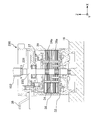
- FIG. 1 is a cross-sectional view of a motor manufacturing apparatus according to a first embodiment.
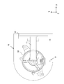
- FIG. 2 is a top view of the motor manufacturing apparatus of FIG.
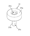
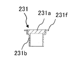
- FIG. 3A is a perspective view of a sensor magnet unit according to the first embodiment.
- FIG. 3B is a perspective view of the sensor magnet unit of FIG. 3A as viewed from another angle.
- FIG. 3C is a top view of the sensor magnet unit of FIG. 3A.
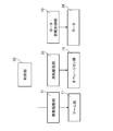
- FIG. 4 is a control block diagram of the motor manufacturing apparatus.
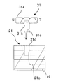
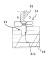
- FIG. 5A is a diagram showing one process for positioning the sensor magnet unit.
- FIG. 5B is a diagram showing one process for positioning the sensor magnet unit.
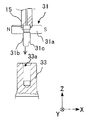
- FIG. 5C is a view showing a process for attaching the positioned sensor magnet unit to the shaft.
- FIG. 5A is a diagram showing one process for positioning the sensor magnet unit.
- FIG. 5B is a diagram showing one process for positioning the sensor magnet unit.
- FIG. 5C is a view showing a process for
- FIG. 6 is a flowchart showing the positioning operation by the motor manufacturing apparatus.
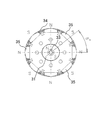
- FIG. 7 is a diagram showing the positional relationship between the main magnet of the rotor and the sensor magnet unit.
- FIG. 8A is a perspective view of a sensor magnet unit according to a modification of the first embodiment.
- FIG. 8B is a perspective view of a sensor magnet unit according to another modification.
- FIG. 8C is a top view of a position adjustment unit engaged with the sensor magnet unit of FIGS. 8A and 8B.
- FIG. 9A is a perspective view of a sensor magnet unit according to another modification.
- FIG. 9B is a top view of a position adjustment unit engaged with the sensor magnet unit of FIG. 9A.
- FIG. 10A is a perspective view of a sensor magnet unit according to another modification.
- FIG. 10B is a top view of a position adjustment unit engaged with the sensor magnet unit of FIG. 10A.
- FIG. 11A is a perspective view of a sensor magnet unit according to another modification.
- 11B is a top view of a position adjustment unit engaged with the sensor magnet unit of FIG. 11A.
- FIG. 12 is a cross-sectional view of a motor manufacturing apparatus according to a second embodiment.
- FIG. 13A is a perspective view of a sensor magnet unit according to a second embodiment.
- 13B is a top view of a sensor magnet unit according to Embodiment 2.
- FIG. FIG. 14A is a cross-sectional view of a sensor magnet unit according to a second embodiment.
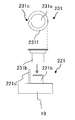
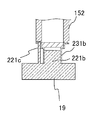
- FIG. 14B is a view showing one process for positioning the sensor magnet unit.
- FIG. 14C is a diagram showing one process for positioning the sensor magnet unit.
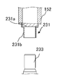
- FIG. 14D is a view showing a process for attaching the positioned sensor magnet unit to the shaft.
- FIG. 15A is a perspective view of a sensor magnet unit according to a modification of the second embodiment.
- FIG. 15B is a top view of a position adjustment unit engaged with the sensor magnet unit of FIG. 15A.
- FIG. 16A is a perspective view of a sensor magnet unit according to another modification. 16B is a top view of a position adjustment unit engaged with the sensor magnet unit of FIG. 16A.
- FIG. 17A is a perspective view of a sensor magnet unit according to another modification.
- FIG. 17B is a top view of a position adjustment unit engaged with the sensor magnet unit of FIG. 17A.
- FIG. 18A is a view showing one process for positioning the sensor magnet unit in the other embodiment.
- FIG. 18B is a view showing one process for positioning the sensor magnet unit in the other embodiment.
- FIG. 18C is
- a "hole” includes both a through hole and a non-through hole.
- an XYZ coordinate system is shown as a three-dimensional orthogonal coordinate system as appropriate.
- the Z-axis direction is the vertical direction.
- the X-axis direction is the right-left direction in FIG. 1 among the directions orthogonal to the Z-axis direction.
- the Y-axis direction is orthogonal to both the X-axis direction and the Z-axis direction.
- a radial direction centered on a central axis (shaft axis) extending in the vertical direction (Z-axis direction) is referred to as “radial direction” and a circumference centered on the central axis
- the direction is called "circumferential direction”.
- the side away from the central axis in the radial direction is called the radially outer side.
- the motor 30 according to the first embodiment shown in FIG. 1 is, for example, a brushless motor.
- the motor 30 includes a shaft 33, a rotor 34, a main magnet 35, a stator 36, a bus bar 37, an external connection terminal 38, a housing 39, and the like.
- the shaft 33 is disposed at the position of the central axis of the motor 30, and is inserted into the cylindrical rotor core 34a. As shown in FIG. 5C, a recess 33a extending in the Z-axis direction is formed at the tip of the shaft 33 on one side in the axial direction.
- the recess 33 a is a true circle centered on the axial center of the shaft 33 when viewed in the Z-axis direction.
- the recess 33a does not need special processing, and can be easily opened by general drilling or the like.
- the pin part 31b of the sensor magnet part 31 mentioned later is attached to the recessed part 33a.
- the rotor 34 has a rotor core 34 a and a main magnet 35 mounted radially outward of the rotor core 34 a.
- the main magnet 35 is provided with N poles and S poles alternately in the circumferential direction.
- the number of poles of the main magnet 35 is eight.
- the main magnet 35 of the rotor shown in the present embodiment is SPM (Surface Permanent Magnet) fixed to the surface of the rotor core, the present invention is not limited to this.
- the main magnet 35 may be replaced by an IPM (Interior Permanent Magnet) fixed inside the rotor core.
- the stator 36 is disposed close to the radially outer side of the rotor 34.
- the stator 36 is an annular member, and has a ring-shaped stator core 36a having teeth portions (not shown) provided at equal intervals in the circumferential direction and a core back portion (not shown) connecting the teeth. .
- the teeth extend radially inward from the core back portion.
- three-phase (U-phase, V-phase, W-phase) excitation coils 32 are wound around the teeth of the stator core 36a.
- the bus bar 37 is a conductive member.
- the bus bar 37 is a plate-like member made of metal.
- the bus bar 37 is a wire that connects the exciting coil 32 and the external connection terminal 38 and supplies a current.
- the external connection terminal 38 is electrically connected to an external power supply (not shown) and supplies a current to the exciting coil 32 through the bus bar 37.
- the shape, material, and the like of the bus bar 37 are not limited to the above.
- the bus bar 37 may be connected to the exciting coil 32, the external connection terminal 38, and the like via a control board described later.
- the housing 39 is provided on the radially outer side of the stator core 36a.
- the housing 39 is cylindrical, and one side in the Z-axis direction is open.
- the housing 39 has a cylindrical shape.
- the shape of the housing may not be limited to a cylinder, but may be a rectangular parallelepiped, a shape combining a rectangular parallelepiped and a cylinder, or the like, and is not particularly limited.
- the housing 39 is made of, for example, aluminum and is formed by die-casting, but may also be formed by other methods such as cutting and forging.
- the material of the housing 39 may be another metal material such as iron, and is not particularly limited.
- the motor 30 further includes a control board.
- the control board has a magnetic sensor (not shown) facing the sensor magnet unit 31 attached to the shaft 33.
- the magnetic sensor is an MR sensor, but may be a Hall element or the like. The magnetic sensor detects the magnetic field of the sensor magnet unit 31 that rotates with the shaft 33. Thereby, the rotational position of the rotor 34 can be detected.
- the control board further includes a microcontroller including a control circuit and the like.
- the microcontroller can calculate the rotational position of the rotor 34 based on the output of the magnetic sensor. Thereby, the drive of the motor 30 can be controlled based on the instruction of the microcontroller or the like. In other words, the rotation and stop of the rotor 34 can be controlled. Therefore, it is possible to rotate the rotor 34 to a predetermined position and control the magnetic pole of the main magnet 35 to a predetermined rotational position, for example, by controlling the energization to the three-phase excitation coil 32.
- the control substrate includes other circuits such as a drive circuit and electronic components.
- the motor 30 further includes a sensor magnet unit 31.
- the sensor magnet unit 31 is attached to the end of the shaft 33 as described later.
- the sensor magnet part 31 has the column-shaped magnet part 31a and the column-shaped pin part 31b whose outer diameter is smaller than the magnet part 31a.
- the pin portion 31 b includes a grip portion 31 e.
- the magnet portion 31a is a permanent magnet having two magnetic poles of N and S.
- the end portion on one side in the axial direction of the pin portion 31 b is attached to the inner peripheral surface of the magnet portion 31 a.
- the magnet portion 31 a has a through hole that penetrates in the axial direction. At least a part of the pin portion 31 b is fixed in the through hole by press fitting, adhesion, or the like.
- the end of the pin 31b on the one side in the axial direction is located on one side in the axial direction of the opening on the one side in the axial direction of the through hole of the magnet 31a.
- the end of the pin portion 31 b on the other side in the axial direction is positioned on the other side in the axial direction with respect to the through hole on the other side in the axial direction of the magnet portion 31 a.
- the gripping portion 31e is an end portion located on the other side in the axial direction of the magnet portion 31a.
- the gripping portion 31 e is gripped by the operation unit 15 described later.
- the first positioning portion 31 c is formed on the pin portion 31 b.
- the first positioning portion 31 c is formed by so-called D-cut processing of a part of the other end of the pin portion 31 b.
- the magnet portion 31a is magnetized in a state where the sensor magnet portion 31 is fixed to the pin portion 31b.
- the magnet part 31a is provided with the magnetic pole which has predetermined angle A1 in the circumferential direction with respect to the position of the 1st positioning part 31c.
- the first positioning portion 31c engages with the second positioning portion 21c formed in the position adjustment portion 21 of the motor manufacturing apparatus 10, as shown in FIG. 5B. This engagement prevents rotation of the sensor magnet 31 relative to the base 19.
- the motor manufacturing apparatus 10 includes an arm portion 11, a support member 13 for supporting one end of the arm portion 11, an operation portion 15, a shaft holding portion 18 and a base portion 19. Prepare.
- the base portion 19 supports the motor 30 and the support member 13 to be manufactured.
- the arm unit 11 moves in the X axis direction, the Y axis direction, and the Z axis direction together with the operation unit 15 under the control of the control unit 50 shown in FIG. 4.
- the operation unit 15 is provided at the other end of the arm unit 11 and rotates under the control of the control unit 50.
- the operation unit 15 holds the holding unit 31 e of the sensor magnet unit 31.
- the shaft holder 18 holds the other end of the shaft 33 from below.
- the positioning device included in the motor manufacturing apparatus 10 includes the operation unit 15 and a position adjustment unit 21 provided in the base unit 19.
- the upper surface of the position adjustment unit 21 is formed flush with the base unit 19.
- the position adjustment unit 21 has a recess 21 o and a second positioning unit 21 c.
- the position adjustment part 21 has the recessed part 21o which the pin part 31b of the sensor magnet part 31 can insert.
- the recess 21 o extends along a direction parallel to the shaft 33.
- the second positioning portion 21c is a step. The second positioning portion 21c engages with the first positioning portion 31c of the pin portion 31b.
- the operation unit 15 may grip not only the grip 31e of the sensor magnet 31 but also the outer periphery of the magnet 31a. In this case, the operation unit 15 grips the outer periphery of the magnet unit 31a, moves to the position adjustment unit 21, and pushes the gripping unit 31e.
- the pin portion 31 b of the magnet portion 31 is inserted into the recess 21 o of the position adjustment portion 21.
- the positioning operation of the sensor magnet unit 31 by the motor manufacturing apparatus 10 is executed by the control unit 50.
- the control unit 50 includes, for example, a microcontroller, a ROM, a processor, a RAM, and the like.
- the microcontroller is provided, for example, on a control substrate and includes a control circuit and the like.
- the ROM stores, for example, a control program for positioning operation.
- the processor controls the positioning operation based on, for example, a control program.
- the RAM temporarily stores, for example, various data under control.
- control unit 50 generates and outputs control signal commands to the movement drive unit 51, the rotation drive unit 52 and the rotor rotation control unit 53.
- the movement drive unit 51 is a drive mechanism that moves the arm unit 11 in the X-axis direction, the Y-axis direction, and the Z-axis direction shown in FIGS. 1 and 2 in accordance with a control signal command from the control unit 50. As shown in FIGS. 5A and 5C, the movement drive unit 51 can move the operation unit 15 provided at one end of the arm unit 11 to the position adjustment unit 21 and the shaft 33.
- the rotation drive unit 52 is a drive mechanism that rotates the operation unit 15 moved to the position adjustment unit 21 according to a control signal command from the control unit 50.
- the sensor magnet unit 31 gripped by the operation unit 15 is also rotated.
- the first positioning portion 31 c is engaged with the second positioning portion 21 c of the position adjustment unit 21.
- the rotor rotation control unit 53 controls energization of the stator 36, that is, rotation of the rotor 34 via a microcontroller or the like provided on a control substrate of the motor 30. For example, as described above, by controlling the energization of the exciting coil 32, the rotor 34 is rotated and stopped so that the magnetic pole of the main magnet 35 has a predetermined rotational position.
- FIG. 6 is a flowchart showing a method of manufacturing a motor including a positioning operation mainly performed by the control unit 50 of the motor manufacturing apparatus 10.
- step S101 the rotational position of the rotor 34 is previously fixed to a predetermined rotational position.
- step S102 the arm unit 11 is moved, and the target sensor magnet unit 31 is gripped by the operation unit 15 (step S102).
- step S103 The arm unit 11 is moved, and the operation unit 15 is moved to the position adjustment unit 21 as shown in FIG. 5A (step S103).
- step S104 The arm unit 11 is lowered while rotating the operation unit 15 (step S104).
- step S105 When the engagement between the first positioning portion 31c and the second positioning portion 21c is completed, that is, when the positioning is completed, the process proceeds to step S106 (step S105).
- the operation unit 15 is fixed, and in a state in which the positioned sensor magnet unit 31 is gripped, the arm unit 11 is raised (step S106).
- the arm unit 11 is moved, and the operation unit 15 is moved to the end of the shaft 33 of the motor 30 as shown in FIG. 5C (step S107).
- step S108 In a state where the arm 11 is lowered and the sensor magnet 31 is fixed by the operation unit 15, the pin 31b is attached to the recess 33a of the shaft 33 by press fitting.
- the step of fixing the rotor 34 may be performed in advance, or may be performed in parallel with the step of positioning the sensor magnet unit 31 (S102 to S106). Alternatively, the step of fixing the rotor 34 may be performed after the step of positioning the sensor magnet unit 31.
- the sensor magnet unit 31 is attached to the shaft 33. Further, the sensor magnet unit is fixed to the shaft 33 in a positioned state. For this reason, as shown in FIG. 7, the sensor magnet unit 31 has a rotational position (a first rotation position) at a predetermined angle ⁇ with respect to the main magnet 35 of the rotor 34 fixed at a predetermined rotation position (first rotation position). 2 rotation position).
- the predetermined angle ⁇ can be a constant angle in all the motors 30 manufactured in the motor manufacturing apparatus 10.
- the sensor magnet unit 31 before the sensor magnet unit 31 is attached to the shaft, the sensor magnet unit 31 is positioned in the axial direction of the shaft 33 by using a positioning device, and with respect to the fixed rotational position of the rotor 34. Positioning at a rotational position having a predetermined angle ⁇ . The sensor magnet unit 31 in the positioned state is attached to the shaft 33. Thereby, the variation in the rotational position of the sensor magnet 31 with respect to the main magnet 35 of the rotor 34 can be suppressed. As a result, it is possible to manufacture a motor in which the variation in the rotational position of the sensor magnet 31 is suppressed, and in the manufactured motor, the detection accuracy of the rotational position of the rotor can be maintained, and torque ripple can be effectively suppressed.
- the arrangement of the sensor magnet 31 affects the detection accuracy of the magnetic sensor. Therefore, by making the rotational positions of the sensor magnet unit 31 and the rotor 34 constant and improving the positional accuracy of the sensor magnet unit, it is possible to increase the accuracy of calculation of the rotational position based on the output of the magnetic sensor by software. Therefore, the torque ripple can be more effectively suppressed when the motor is driven. Further, since it is not necessary to adjust software for each of the assembled motors 30, the manufacturing process of the motor can be simplified, and the manufacturing cost of the motor 30 can be suppressed.
- the process from positioning of the sensor magnet unit 31 to attachment to the shaft 33 can be performed by one motor manufacturing apparatus 10, the working time required for assembly, movement of members, etc. can be shortened. .
- the rotor 34 and the sensor magnet unit 31 can be accurately positioned and fixed by processing the sensor magnet unit 31 without performing special processing on the shaft 33.
- the sensor magnet unit 31 includes a magnet unit 31a having a magnetic pole and a pin unit 31b attached to the magnet unit 31a.
- the shaft 33 includes an axially extending recess 33a therein.
- the pin portion 31 b of the sensor magnet portion 31 is attached to the recess 33 a of the shaft 33. Therefore, it is possible to manufacture the outer diameter of the sensor magnet portion 31 smaller than the outer diameter of the shaft. Therefore, the sensor magnet 31 can be attached to the shaft 33 before assembling the motor 30, and the assembling process of the motor 30 becomes easy.
- the 1st positioning part 31c of sensor magnet part 31 had what is called D cut processing shape, it is not limited to this.
- the first positioning portion and the second positioning portion may have any shape as long as they can prevent the rotation of the sensor magnet 31 by physically contacting them.
- FIG. 8A, FIG. 8B, and FIG. 8C are figures which show the other example of a 1st and 2nd positioning part.
- the 1st positioning part 311c of the sensor magnet part 311 may be a square hole opened to the center of the end surface (tip of the pin part 31b) of the axial direction of the pin part 31b.
- the first positioning portion 311c square hole
- the first positioning portion 311c and the second positioning portion 211c Is engaged also at a position rotated 180 degrees from a predetermined rotational position.
- the position rotated 180 degrees from the predetermined rotational position is not the exact position of the first positioning portion 311 c and the second positioning portion 211 c. That is, accurate positioning can not be performed. Therefore, it is desirable that the first positioning portion 311c be disposed so as to be deviated outward from the center of the circular end surface of the pin portion 31b.
- the first positioning portion 311 c and the second positioning portion 211 c do not engage at a position rotated 180 degrees from the predetermined rotational position, and the first positioning portion 311 c and the second positioning portion 211 c are correctly determined. It can be engaged in position.
- the 1st positioning part 312c of the sensor magnet part 312 may be a slit cut in from the end surface of the axial direction of pin part 31b.
- the first positioning portion 312 c is formed at the center of the circular end surface of the pin portion 31 b.
- the main magnet 35 is a magnet of six poles
- the first positioning portion 312c engages with the second positioning portion 211c even at a position rotated 180 degrees from a predetermined rotational position. Therefore, the sensor magnet unit 312 can not be fixed at a predetermined position.
- the first positioning portion 312c be disposed on the outer peripheral side of the center of the circular end face of the pin portion 31b.
- the first positioning portion 312c and the second positioning portion 211c do not engage with each other at a position rotated 180 degrees from the predetermined rotational position, and the first positioning portion 311c and the second positioning portion 211c are correctly determined. It can be engaged in position.
- the second positioning unit 211c is provided in the position adjustment unit 211.
- the first positioning portion 311 c and the first positioning portion 312 c can be engaged with, for example, the second positioning portion 211 c.
- the position adjustment unit 211 includes a concave portion into which the pin portions 31 b of the sensor magnet portions 311 and 312 can be inserted.
- the second positioning portion 211c protrudes from the bottom of the recess 211o in the positive direction of the Z-axis, and is engageable with the first positioning portions 311c and 312c. As shown in FIG. 8C, when viewed from the axial direction, the second positioning portion 211c is positioned at the center of the recess 211o.
- the main magnet 35 is a magnet of six poles
- the second positioning portion 211c is also disposed on the outer peripheral side of the center of the recess 211o in accordance with the positions of the first positioning portions 311c and 312c.
- FIG. 9A, FIG. 10A, and FIG. 11A are figures which each show the sensor magnet part which concerns on another modification, and a position adjustment part.
- the sensor magnet portions 313, 314, and 315 differ from the above example in that the first positioning portions 313d, 314d, and 315d are formed on the magnet portion 31a side, respectively. .
- the first positioning portions 313d, 314d, and 315d are formed on the magnet portion 31a side. Therefore, processing can be easily performed as compared with the case where the first positioning portions 313d, 314d, and 315d are formed on the pin portion 31b.
- the 1st positioning part 313d of the sensor magnet part 313 may be a hole opened to a part of one side of the magnet part 31a.
- the position adjustment part 213 has the recessed part 213o which the pin part 31b of the sensor magnet part 313 can insert, and the protrusion part 213d which the 1st positioning part 313d can engage.
- the outer shape of the projecting portion 213d is substantially circular.
- the 1st positioning part 314d of the sensor magnet part 314 may be the step part of one side of the magnet part 31a.
- the position adjustment part 214 has the recessed part 214o which the pin part 31b of the sensor magnet part 314 can insert, and the protrusion part 214d which the 1st positioning part 314d can engage.
- the outer shape of the protrusion 214d is substantially rectangular.
- the 1st positioning part 315d of the sensor magnet part 315 may be a projection part which protrudes in a radial direction outer side from the circumferential direction outer surface of the magnet part 31a.
- the position adjustment unit 215 has a recess 215o into which the pin 31b of the sensor magnet 315 can be inserted, and a protrusion 215d to which the first positioning unit 315d can be engaged.
- the outer shape of the protrusion 215 d is substantially U-shaped.
- the form of the attachment portion of the sensor magnet portion and the shaft is different from that of the first embodiment, and accordingly the form of the first positioning portion and the second positioning portion is also different.
- differences from the first embodiment will be mainly described.
- the shaft 233 is disposed at the central axis of the motor 230. Unlike the above embodiment, no recess is formed on the axial end face of the shaft 233.
- the sensor magnet unit 231 is attached to the end of the shaft 233 as described later.
- the sensor magnet part 231 contains the magnet part 231a which has a magnetic pole, and the holder part 231b holding the magnet part 231a.
- the holder portion 231 b includes a cylindrical portion to which the shaft 233 is attached.
- the sensor magnet portion 231 further includes a flange portion 231 f that protrudes radially outward. The flange portion 231f is gripped by the operation unit 152 shown in FIG.
- the first positioning portion 231c is formed on the flange portion 231f. As shown in FIGS. 13A and 13B, in the present embodiment, the first positioning portion 231c is a notch.
- the magnetic pole position of the sensor magnet portion 231 has a predetermined angle with respect to the position in the circumferential direction of the first positioning portion 231c. In other words, the magnetic pole position of the sensor magnet portion 231 is deviated by a predetermined angle with respect to the position in the circumferential direction of the first positioning portion 231c.
- the second positioning portion 221c shown in FIG. 14B is inserted into and engaged with the first positioning portion 231c. By this engagement, the rotation of the sensor magnet unit 231 can be blocked.
- the flange portion 231 f is gripped by the operation unit 152 as shown in FIG. 14C.
- the positioning device includes an operation unit 152 and a position adjusting unit 221 provided on the base unit 19.
- the position adjustment portion 221 has a pin-shaped second positioning portion 221 c protruding above the base portion 19.
- the second positioning portion 221 c is inserted into the notch of the first positioning portion 231 c of the sensor magnet portion 231.
- the position adjustment portion 221 has a holder support portion 221 b protruding above the base portion 19.
- the holder support portion 221 b can be inserted into the cylindrical portion of the holder portion 231 b of the sensor magnet portion 231.
- the second positioning portion 221c and the holder support portion 221b extend in a direction parallel to the axis of the shaft 233.
- the sensor magnet unit 231 is positioned along the direction parallel to the axis of the shaft 233, and the position in the circumferential direction is also fixed. Subsequently, as shown in FIG. 14D, in a state where the positioned sensor magnet unit 231 is gripped by the operation unit 152, the sensor magnet unit 231 is moved to the end of the shaft 233 of the motor 230. In a state where the position of the sensor magnet portion 231 is fixed, the end of the shaft 233 is attached by press-fitting in the holder portion 231b. As a result, the sensor magnet unit 231 is attached to the shaft 233.
- the step of fixing the rotor 34 may be performed prior to the step of positioning the sensor magnet portion 231 or may be performed in parallel. Alternatively, the step of fixing the rotor 34 may be performed after the step of positioning the sensor magnet unit 231.
- the sensor magnet unit 231 includes a magnet unit 231a having a magnetic pole and a holder unit 231b that holds the magnet unit.
- the holder portion 231 b includes a cylindrical portion. An axial end of the shaft 233 is attached to the cylindrical portion of the holder portion 231b. Therefore, the sensor magnet unit 231 can be attached to the shaft 233 without special processing of the shaft 233. As a result, the manufacturing process of the motor can be simplified.
- the 1st positioning part 231c of sensor magnet part 231 had notch shape, it is not limited to this.
- the first positioning portion 2311c of the sensor magnet portion 2311 is a hole penetrating the flange portion 2311f.
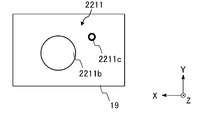
- the first positioning portion 2311 c engages with the second positioning portion 2211 c of the position adjustment portion 2211 shown in FIG. 15B.
- the second positioning portion 2211 c has a pin shape protruding from the base portion 19.
- the second positioning portion 2211c is inserted into and engaged with the hole of the first positioning portion 2311c at the time of positioning operation.
- the position adjustment unit 2211 has a holder support 2211 b protruding above the base 19.
- the holder support portion 2211 b can be inserted into the cylindrical portion of the holder portion 231 b of the sensor magnet portion 2311.
- FIG. 16A is a view showing a sensor magnet unit 2312 according to another modification.
- the first positioning portion 2312c instead of the flange portion, has a projection that protrudes radially outward from the upper edge portion of the holder portion 231b.
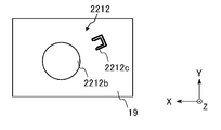
- the first positioning portion 2312 c engages with the second positioning portion 2212 c of the position adjustment portion 2212 shown in FIG. 16B.
- the second positioning portion 2212 c protrudes from the base portion 19.
- the second positioning portion 2212 c has a substantially U-shaped outer shape shown in FIG. 16B.
- the second positioning portion 2212c can block the rotation of the sensor magnet portion 2312 when it engages with the first positioning portion 2312c at the time of positioning operation.
- the position adjustment portion 2212 has a holder support portion 2212 b protruding above the base portion 19.
- the holder support portion 2212 b can be inserted into the cylindrical portion of the holder portion 231 b of the sensor magnet portion 2312.
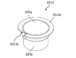
- FIG. 17A is a perspective view of a sensor magnet unit 2313 according to another modification.
- the first positioning portion 2313c has a bent shape in which a part of the flange portion 2313f is bent. More specifically, the flange portion 2313 f has an extending portion extending in the axial direction from the end face of the flange portion 2313 f. The extension portion is formed, for example, by bending a part of the flange portion 2313 f.
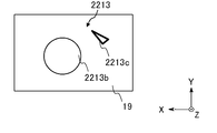
- the first positioning portion 2313 c when viewed in the axial direction, has a substantially triangular outer shape. The first positioning portion 2313c engages with the second positioning portion 2213c of the position adjustment portion 2213 shown in FIG. 17B.
- the second positioning portion 2213 c protrudes from the base portion 19.
- the second positioning portion 2213c has a form capable of blocking the rotation of the sensor magnet portion 2312 when engaged with the first positioning portion 2313c at the time of positioning operation.
- the position adjustment unit 2213 also has a holder support 2213 b protruding above the base 19. The holder support portion 2213 b can be inserted into the cylindrical portion of the holder portion 231 b of the sensor magnet portion 2313.
- the position adjustment part 2214 which positions the sensor magnet part 31 of Embodiment 1 may be provided with the movable member 2214a.
- the movable member 2214a is a rectangular parallelepiped.
- the movable member 2214 a slides in a direction orthogonal to the insertion direction of the pin portion 31 b of the sensor magnet portion 31.
- FIGS. 18B and 18C when the pin portion 31b is inserted into the recess 2214o of the position adjustment portion 2214, the movable member 2214a moves, and the front surface portion 2214c which is the second positioning portion is the first of the pin portions 31b.
- the flat portion of the positioning portion 31c is contacted.
- the upper surface of the position adjustment unit 21 may not be formed flush with the base unit 19.
- the block shown in FIGS. 5A and 5B may be formed on the base portion 19, and a recess may be formed in the block to provide the second positioning portion 21c.
- the operation units 15 and 152 hold the sensor magnet units 31 and 231 in the first and second embodiments, the present invention is not limited to this.
- the operation unit 15, 152 may hold the sensor magnet unit 31, 231 by air suction, adsorption by a magnetic material or the like.
- the number of poles of the main magnet 35 is eight in the first and second embodiments, it may be more or less. Moreover, in said embodiment, although it is a three-phase motor, the motor of other numbers of phases, such as five phases and seven phases, may be sufficient.
- the fixing of the rotor 34 is performed electrically, but is not limited thereto.
- the motor manufactured by the above manufacturing method can be used, for example, in various applications such as electric power steering and a compressor.
Landscapes
- Engineering & Computer Science (AREA)
- Power Engineering (AREA)
- Manufacturing & Machinery (AREA)
- Microelectronics & Electronic Packaging (AREA)
Abstract
モータ30の製造方法は、メインマグネット35が第1回転位置に位置する状態でロータ34を固定する工程と、位置決め装置15,21を用いて、センサマグネット部31を、シャフト33の軸と平行な軸に沿って位置決めするとともに、第1回転位置に対し所定の角度を有する第2回転位置に位置決めする工程と、位置決め装置15,21により位置決めされたセンサマグネット部31をシャフト33に取り付ける工程と、を含むことを特徴とする。
Description
本発明は、モータの製造方法、センサマグネット部の位置決め装置、モータ、及びモータ製造装置に関する。
ブラシレスモータは、ロータの回転位置の検出手段を備える。ロータの回転位置の検出手段は、例えば、ロータの回転軸であるシャフトに固定されたセンサマグネット部と、センサマグネット部に対向するように配置した磁気センサとを備える。かかる検出手段は、ロータと同期して回転するセンサマグネット部の磁界の変化を磁気センサによって検出することにより、ロータの回転位置を検出する。例えば、特許文献1には、従来の方法の一例として、シャフトとセンサマグネット部とをそれぞれ加工して平面部を形成し、同平面部を基準として、センサマグネット部をロータのマグネットの位置に対応させて着磁するモータが提案されている。
モータを回転させるため、ステータのコイルへ通電をすると、制御基板とコイルとを接続する導線に電流が流れて導線の周囲に磁場が形成される。制御基板に配置される磁気センサは磁場の影響を受けるため、回転位置の検出精度が低下し、トルクリップルが増大する。トルクリップルの増大を防ぐため、ソフトウエアにより検出信号にフィルターをかけて回転位置を調整する場合がある。しかし、ロータの製造時に、ロータのマグネットの回転位置に対するセンサマグネット部の周方向の着磁位置(周方向における磁極の位置)にばらつきがあると、磁気センサに影響する磁場にもばらつきが生じる。この結果、モータ毎にフィルタリングのソフトウエアの調整が必要となり、製造コストが増大する。
ロータのマグネットの回転位置に対するセンサマグネット部の周方向の着磁位置を一定にするため、例えば、上記従来例のように、シャフトにDカット加工等、位置決めのための加工を施すことが考えられる。しかし、シャフトの加工部分とロータのマグネットとの位置合わせが別に必要となり、製造工程が増え製造コストを増大させる。
本発明は、より簡単にモータの回転位置の検出精度を維持することが可能なモータの製造方法、センサマグネット部の位置決め装置、モータ、及びモータ製造装置を提供することを目的とする。
本願の例示的な一実施形態のモータの製造方法は、励磁コイルを含むステータと、シャフト及びメインマグネットを有し、前記ステータの径方向内側に回転可能に設けられるロータと、ロータの回転位置を検出するためのセンサマグネット部とを備えるモータの製造方法である。同モータの製造方法は、メインマグネットが第1回転位置に位置する状態でロータを固定する工程と、位置決め装置を用いて、センサマグネット部を、シャフトの軸と平行な軸に沿って位置決めするとともに、第1回転位置に対し所定の角度を有する第2回転位置に位置決めする工程と、位置決め装置により位置決めされたセンサマグネット部をシャフトに取り付ける工程と、を含む。
本願の例示的な実施形態によれば、ロータのメインマグネットに対するセンサマグネット部の回転位置のばらつきを抑えることでき、モータの回転位置の検出精度を維持してトルクリップルを抑制できるモータを製造することができる。
以下、図面を参照しながら、本発明の実施形態について説明する。なお、本発明の範囲は、以下の実施形態に限定されず、本発明の技術的思想の範囲内で任意に変更可能である。
以下の説明において、第1位置決め部と第2位置決め部との「係合」は、第1位置決め部と第2位置決め部とが物理的に接触することによって、第1位置決め部の移動が阻止される状態になることを含む。また、「孔」とは、貫通孔及び非貫通孔のいずれも含む。
図面においては、適宜3次元直交座標系としてXYZ座標系を示す。XYZ座標系において、Z軸方向は、上下方向とする。X軸方向は、Z軸方向と直交する方向のうち図1の左右方向とする。Y軸方向は、X軸方向とZ軸方向との両方と直交する方向とする。また、特に断りのない限り、以下の説明においては、上下方向(Z軸方向)に延びる中心軸(シャフト軸)を中心とする径方向を「径方向」と呼び、中心軸を中心とする周方向を「周方向」と呼ぶ。中心軸から径方向に離れる側を径方向外側と呼ぶ。
(実施形態1)
[1-1.構成]
<モータ>
図1に示す実施形態1に係るモータ30は、例えばブラシレスモータである。モータ30は、シャフト33、ロータ34、メインマグネット35、ステータ36、バスバー37、外部接続端子38、及びハウジング39等を備える。
[1-1.構成]
<モータ>
図1に示す実施形態1に係るモータ30は、例えばブラシレスモータである。モータ30は、シャフト33、ロータ34、メインマグネット35、ステータ36、バスバー37、外部接続端子38、及びハウジング39等を備える。
シャフト33は、モータ30の中心軸の位置に配され、円筒状のロータコア34aに挿入される。図5Cに示すように、シャフト33の軸方向一方側の先端には、Z軸方向に延びる凹部33aが形成される。凹部33aは、Z軸方向視すると、シャフト33の軸心を中心とする真円状となっている。凹部33aは、特殊な加工が必要なく、一般的なドリル加工等によって、簡易に開けられる。凹部33aには、後述するセンサマグネット部31のピン部31bが取り付けられる。
ロータ34は、ロータコア34aと、ロータコア34aの径方向外側に取り付けられたメインマグネット35とを有する。メインマグネット35は、図7に示すように、N極とS極とが周方向に交互に設けられる。メインマグネット35の極数は、8である。なお、本実施形態において示したロータのメインマグネット35は、ロータコアの表面に固定されたSPM(Surface Permanent Magnet)としたが、これに限らない。メインマグネット35は、ロータコアの内部に固定されたIPM(Interior Permanent Magnet)に代えてもよい。
ステータ36は、ロータ34の径方向外側に近接して配される。ステータ36は、円環状の部材であり、周方向に等間隔で設けられたティース部(図示省略)と、ティース部を連結するコアバック部(図示省略)とを有するリング状のステータコア36aを有する。ティース部は、コアバック部から径方向内側へ向かって延びる。ステータコア36aのティース部には、例えば三相(U相、V相、W相)の励磁コイル32が巻きつけられる。
バスバー37は、導電性の部材である。本実施形態では、バスバー37は、金属製の板状の部材である。バスバー37は、励磁コイル32と外部接続端子38とを接続し、電流を供給する配線である。外部接続端子38は、外部電源(図示省略)と電気的に接続され、バスバー37を通じて励磁コイル32に電流を供給する。なお、バスバー37の形状や材料等は、上記に限定されるものではない。また、バスバー37は、後述の制御基板を介して、励磁コイル32や外部接続端子38等と接続されてもよい。
ハウジング39は、ステータコア36aの径方向外側に設けられる。ハウジング39は、筒状であり、Z軸方向の一方側が開口する。本実施形態では、ハウジング39は、円筒形状である。なお、ハウジングの形状は、円筒以外にも、直方体や直方体と円筒とを組み合わせた形状等であってもよく、特に限定されない。ハウジング39は、例えば、アルミニウム製であり、ダイカスト加工により形成されるが、切削加工及び鍛造等、その他の方法でも形成される。なお、ハウジング39の材料は、アルミニウム以外にも、鉄等の他の金属材料であってもよく、特に限定されるものではない。
図示は省略するが、モータ30はさらに、制御基板を備える。制御基板は、シャフト33に取り付けられたセンサマグネット部31に対向する磁気センサ(図示省略)を有する。本実施形態では、磁気センサはMRセンサであるが、ホール素子等であってもよい。磁気センサは、シャフト33とともに回転するセンサマグネット部31の磁界を検出する。これにより、ロータ34の回転位置を検出することができる。
制御基板はさらに、制御回路等を含むマイクロコントローラを備える。マイクロコントローラは、磁気センサの出力に基づいてロータ34の回転位置を算出することができる。これにより、マイクロコントローラの指令等に基づいて、モータ30の駆動を制御することができる。言い換えると、ロータ34の回転及び停止を制御することができる。そのため、例えば、3相の励磁コイル32への通電を制御することにより、ロータ34を回転させて所定の位置とし、メインマグネット35の磁極を所定の回転位置とすることができる。なお、図示は省略するが、制御基板は、駆動回路等の他の回路や電子部品等を含む。
モータ30はさらに、センサマグネット部31を備える。
<センサマグネット部>
センサマグネット部31は、後述するようにシャフト33の端部に取り付けられる。
センサマグネット部31は、後述するようにシャフト33の端部に取り付けられる。
図3A及び図3Bに示すように、センサマグネット部31は、円柱状のマグネット部31aと、マグネット部31aより外径が小さい円柱状のピン部31bと、を有する。ピン部31bは、把持部31eを備える。マグネット部31aは、NとSの二極の磁極を有する永久磁石である。ピン部31bの軸方向一方側の端部は、マグネット部31aの内周面に取り付けられる。より詳細には、マグネット部31aは軸方向に貫通する貫通孔を有する。ピン部31bの少なくとも一部は、当該貫通孔内に圧入や接着等により固定される。ピン部31bの軸方向一方側の端部は、マグネット部31aの貫通孔の軸方向一方側の開口よりも、軸方向一方側に位置する。ピン部31bの軸方向他方側の端部は、マグネット部31aの軸方向他方側の貫通孔よりも軸方向他方側に位置する。把持部31eは、マグネット部31aの軸方向他方側に位置する端部である。把持部31eは、後述するオペレーション部15により把持される。
ピン部31bには、第1位置決め部31cが形成される。本実施形態では、第1位置決め部31cは、ピン部31bの他方の端部の一部を、いわゆるDカット加工することにより形成される。ピン部31bに第1位置決め部31cが形成された後、センサマグネット部31がピン部31bに固定された状態で、マグネット部31aは着磁される。これにより、マグネット部31aは、図3Cに示すように、第1位置決め部31cの位置に対し周方向に所定の角度A1を有する磁極が付与される。
後述するように、第1位置決め部31cは、図5Bに示すように、モータ製造装置10の位置調整部21に形成される第2位置決め部21cと係合する。この係合は、ベース部19に対するセンサマグネット部31の回転を阻止する。
<モータの製造装置>
図1及び図2に示すように、モータ製造装置10は、アーム部11と、アーム部11の一端を支持する支持部材13と、オペレーション部15と、シャフト保持部18と、ベース部19とを備える。ベース部19は、製造対象のモータ30及び支持部材13を支持する。アーム部11は、図4に示す制御部50の制御により、オペレーション部15とともにX軸方向、Y軸方向、及びZ軸方向に移動する。オペレーション部15は、アーム部11の他端に設けられ、制御部50の制御により回転する。オペレーション部15は、センサマグネット部31の把持部31eを把持する。シャフト保持部18は、シャフト33の他端部を下から保持する。これにより、ベース部19上に載置されたモータ30のシャフト33の一端部にセンサマグネット部31を取り付けるときに、シャフト33が下がることを防止できる。
図1及び図2に示すように、モータ製造装置10は、アーム部11と、アーム部11の一端を支持する支持部材13と、オペレーション部15と、シャフト保持部18と、ベース部19とを備える。ベース部19は、製造対象のモータ30及び支持部材13を支持する。アーム部11は、図4に示す制御部50の制御により、オペレーション部15とともにX軸方向、Y軸方向、及びZ軸方向に移動する。オペレーション部15は、アーム部11の他端に設けられ、制御部50の制御により回転する。オペレーション部15は、センサマグネット部31の把持部31eを把持する。シャフト保持部18は、シャフト33の他端部を下から保持する。これにより、ベース部19上に載置されたモータ30のシャフト33の一端部にセンサマグネット部31を取り付けるときに、シャフト33が下がることを防止できる。
<位置決め装置>
モータ製造装置10が有する位置決め装置は、上記オペレーション部15と、ベース部19に設けられた位置調整部21とを備える。位置調整部21の上面は、ベース部19と面一に形成される。位置調整部21は、凹部21oと、第2位置決め部21cと、を有する。図2及び図5Aに示すように、位置調整部21は、センサマグネット部31のピン部31bが挿入可能な凹部21oを有する。図5A及び図5Bに示すように、凹部21oは、シャフト33と平行な方向に沿って延びる。図5A及び図5Bに示すように、本実施形態では、第2位置決め部21cは、段部である。第2位置決め部21cは、ピン部31bの第1位置決め部31cと係合する。
モータ製造装置10が有する位置決め装置は、上記オペレーション部15と、ベース部19に設けられた位置調整部21とを備える。位置調整部21の上面は、ベース部19と面一に形成される。位置調整部21は、凹部21oと、第2位置決め部21cと、を有する。図2及び図5Aに示すように、位置調整部21は、センサマグネット部31のピン部31bが挿入可能な凹部21oを有する。図5A及び図5Bに示すように、凹部21oは、シャフト33と平行な方向に沿って延びる。図5A及び図5Bに示すように、本実施形態では、第2位置決め部21cは、段部である。第2位置決め部21cは、ピン部31bの第1位置決め部31cと係合する。
なお、オペレーション部15は、センサマグネット部31の把持部31eだけではなく、マグネット部31aの外周を把持してもよい。この場合、オペレーション部15は、マグネット部31aの外周を把持して位置調整部21まで移動し、把持部31eを押す。マグネット部31のピン部31bは、位置調整部21の凹部21oに挿入される。
<制御部>
モータ製造装置10によるセンサマグネット部31の位置決め動作は、制御部50により実行される。制御部50は、例えば、マイクロコントローラ、ROM、プロセッサ、RAM等を含む。マイクロコントローラは、例えば、制御基板上に設けられ、制御回路等を含む。ROMは、例えば、位置決め動作の制御プログラムを格納する。プロセッサは、例えば、制御プログラムに基づいて位置決め動作を制御する。RAMは、例えば、制御中の各種データを一時的に記憶する。
モータ製造装置10によるセンサマグネット部31の位置決め動作は、制御部50により実行される。制御部50は、例えば、マイクロコントローラ、ROM、プロセッサ、RAM等を含む。マイクロコントローラは、例えば、制御基板上に設けられ、制御回路等を含む。ROMは、例えば、位置決め動作の制御プログラムを格納する。プロセッサは、例えば、制御プログラムに基づいて位置決め動作を制御する。RAMは、例えば、制御中の各種データを一時的に記憶する。
図4に示すように、制御部50は、移動駆動部51、回転駆動部52及びロータ回転制御部53に対する制御信号指令を生成し出力する。
移動駆動部51は、制御部50からの制御信号指令に応じて、アーム部11を、図1及び図2に示すX軸方向、Y軸方向、及びZ軸方向に移動させる駆動機構である。図5A及び図5Cに示すように、移動駆動部51は、アーム部11の一端に設けられたオペレーション部15を、位置調整部21及びシャフト33まで移動させることができる。
回転駆動部52は、制御部50からの制御信号指令に応じて位置調整部21に移動されたオペレーション部15を回転させる駆動機構である。回転駆動部52によってオペレーション部15が回転すると、オペレーション部15に把持されたセンサマグネット部31も回転する。この動作の結果、第1位置決め部31cは、位置調整部21の第2位置決め部21cと係合される。
ロータ回転制御部53は、モータ30の制御基板上に設けられたマイクロコントローラ等を介して、ステータ36への通電、すなわち、ロータ34の回転を制御する。例えば、上述のように、励磁コイル32への通電を制御することによりメインマグネット35の磁極が所定の回転位置となるようロータ34を回転及び停止させる。
[1-2.動作]
図6は、モータ製造装置10の主に制御部50により実行される位置決め動作を含むモータの製造方法を示すフローチャートである。
図6は、モータ製造装置10の主に制御部50により実行される位置決め動作を含むモータの製造方法を示すフローチャートである。
上述の通り、最初に、予めロータ34の回転位置を、所定の回転位置に固定する(ステップS101)。次に、アーム部11を移動させ、対象となるセンサマグネット部31をオペレーション部15により把持する(ステップS102)。アーム部11を移動させ、図5Aに示すようにオペレーション部15を位置調整部21まで移動させる(ステップS103)。オペレーション部15を回転させながらアーム部11を下降させる(ステップS104)。これにより、図5Bに示すようにオペレーション部15により把持されたセンサマグネット部31の第1位置決め部31cと位置調整部21の第2位置決め部21cとが係合する。第1位置決め部31cと第2位置決め部21cとの係合が完了した場合、つまり位置決めが完了した場合は、ステップS106に進む(ステップS105)。オペレーション部15を固定させ、位置決めされたセンサマグネット部31を把持した状態で、アーム部11を上昇させる(ステップS106)。アーム部11を移動させ、オペレーション部15を図5Cに示すようにモータ30のシャフト33の端部まで移動させる(ステップS107)。アーム部11を下降させ、オペレーション部15によりセンサマグネット部31を固定した状態で、ピン部31bをシャフト33の凹部33aに圧入により取り付ける(ステップS108)。
なお、ロータ34を固定するステップ(S101)は、予め行ってもよいし、センサマグネット部31の位置決めするステップ(S102~S106)と並行して行ってもよい。或いは、ロータ34を固定する工程は、センサマグネット部31の位置決めする工程より後に行ってもよい。
以上により、センサマグネット部31はシャフト33に取り付けられる。また、センサマグネット部は位置決めされた状態でシャフト33に固定される。このため、図7に示すように、センサマグネット部31は、所定の回転位置(第1の回転位置)に固定されたロータ34のメインマグネット35に対して所定の角度θを有する回転位置(第2回転位置)に取り付けられる。この所定の角度θは、モータ製造装置10において製造されるモータ30全てにおいて一定の角度とすることができる。
実施形態1によれば、センサマグネット部31をシャフトに取り付ける前に、位置決め装置を用いて、センサマグネット部31を、シャフト33の軸方向に位置決めするとともに、ロータ34の固定された回転位置に対し所定の角度θを有する回転位置に位置決めする。位置決めされた状態のセンサマグネット部31をシャフト33に取り付ける。これにより、ロータ34のメインマグネット35に対するセンサマグネット部31の回転位置のばらつきが抑えられる。この結果、センサマグネット部31の回転位置のばらつきを抑えたモータを製造することができ、当該製造されたモータでは、ロータの回転位置の検出精度を維持でき、トルクリップルを効果的に抑制できる。より具体的には、センサマグネット部31の配置は、磁気センサの検出精度に影響を与える。そのため、センサマグネット部31とロータ34との回転位置を一定にし、センサマグネット部の位置精度を高めることにより、ソフトウエアによる磁気センサの出力に基づいた回転位置の算出の精度を上げることができる。よって、モータの駆動時においてトルクリップルを一層効果的に抑制できる。また、組み立てられた各モータ30毎にソフトウエアを調整する必要がないため、モータの製造工程を簡略化でき、モータ30の製造コストを抑制することができる。
実施形態1によれば、センサマグネット部31の位置決めからシャフト33への取り付けまでを一つのモータ製造装置10で行うことができるため、組立てや部材の移動等に要する作業時間を短縮することができる。
実施形態1によれば、シャフト33に特別な加工を行うことなく、センサマグネット部31を加工するだけで、ロータ34とセンサマグネット部31とを精度よく位置決め及び固定することができる。
実施形態1によれば、センサマグネット部31は、磁極を有するマグネット部31aとマグネット部31aに取り付けられたピン部31bとを含む。シャフト33は、内部に軸方向に延びる凹部33aを含む。センサマグネット部31のピン部31bは、シャフト33の凹部33aに取り付けられる。このため、センサマグネット部31の外径をシャフトの外径よりも小さく製造することが可能となる。よって、モータ30を組み付ける前にシャフト33にセンサマグネット部31を取り付けることができ、モータ30の組み付け工程が容易になる。
[1-3.変形例]
上述の実施形態1において、センサマグネット部31の第1位置決め部31cは、いわゆるDカット加工形状を有していたが、これに限定されない。第1位置決め部と第2位置決め部は、物理的に接触することによりセンサマグネット部31の回転を阻止することが可能な形状であれば、どのような形状であってもよい。
上述の実施形態1において、センサマグネット部31の第1位置決め部31cは、いわゆるDカット加工形状を有していたが、これに限定されない。第1位置決め部と第2位置決め部は、物理的に接触することによりセンサマグネット部31の回転を阻止することが可能な形状であれば、どのような形状であってもよい。
なお、後述する例及び実施形態の説明においては、同様の構成又は機能を有する構成要素については、同じ符号を付し、その説明を省略する場合がある。
図8A,図8B,図8Cは、第1及び第2位置決め部の他の例を示す図である。図8Aに示すように、センサマグネット部311の第1位置決め部311cは、ピン部31bの軸方向の端面(ピン部31bの先端)の中心に開口する四角穴であってもよい。
なお、図7に示すメインマグネット35が6極のマグネットである場合、第1位置決め部311c(四角穴)がピン部31bの端面の中心にあると、第1位置決め部311cと第2位置決め部211cとは所定の回転位置から180度回転した位置においても係合する。この所定の回転位置から180度回転した位置は、第1位置決め部311cと第2位置決め部211cとの正確な位置ではない。すなわち、正確な位置決めができない。そのため、第1位置決め部311cは、ピン部31bの円形の端面の中心より外周側に偏って配置されるのが望ましい。これにより、第1位置決め部311cと第2位置決め部211cとは所定の回転位置から180度回転した位置において係合することがなく、第1位置決め部311cと第2位置決め部211cとを所定の正しい位置において係合することができる。
図8Bに示すように、センサマグネット部312の第1位置決め部312cは、ピン部31bの軸方向の端面から切り込まれたスリットであってもよい。軸方向から見たときに、第1位置決め部312cは、ピン部31bの円形の端面の中心に形成される。図8Aの例と同様に、メインマグネット35が6極のマグネットである場合、第1位置決め部312cは、第2位置決め部211cと、所定の回転位置から180度回転した位置においても係合してしまい、センサマグネット部312を所定の位置において固定することができない。そのため、第1位置決め部312cは、ピン部31bの円形の端面の中心より外周側に偏って配置されるのが望ましい。これにより、第1位置決め部312cと第2位置決め部211cとは所定の回転位置から180度回転した位置において係合することがなく、第1位置決め部311cと第2位置決め部211cとを所定の正しい位置において係合することができる。
図8Cに示すように、第2位置決め部211cは、位置調整部211に設けられる。第1位置決め部311c及び第1位置決め部312cは、例えば第2位置決め部211cと係合することができる。位置調整部211は、センサマグネット部311及び312のピン部31bが挿入可能な凹部を含む。第2位置決め部211cは、凹部211oの底部よりZ軸の正方向に突出し、第1位置決め部311c及び312cと係合可能である。なお、図8Cに示すように、軸方向から見たときに、第2位置決め部211cは、凹部211oの中央に位置する。上述のように、メインマグネット35が6極のマグネットである場合、第1位置決め部311c、312cはピン部31bの円形の端面の中心より外周側に偏って配置されるのが望ましい。この場合、第2位置決め部211cも、第1位置決め部311c、312cの位置に合わせて、凹部211oの中心より外周側に偏って配置されるのが望ましい。
図8Cに示すように、第2位置決め部211cは、位置調整部211に設けられる。第1位置決め部311c及び第1位置決め部312cは、例えば第2位置決め部211cと係合することができる。位置調整部211は、センサマグネット部311及び312のピン部31bが挿入可能な凹部を含む。第2位置決め部211cは、凹部211oの底部よりZ軸の正方向に突出し、第1位置決め部311c及び312cと係合可能である。なお、図8Cに示すように、軸方向から見たときに、第2位置決め部211cは、凹部211oの中央に位置する。上述のように、メインマグネット35が6極のマグネットである場合、第1位置決め部311c、312cはピン部31bの円形の端面の中心より外周側に偏って配置されるのが望ましい。この場合、第2位置決め部211cも、第1位置決め部311c、312cの位置に合わせて、凹部211oの中心より外周側に偏って配置されるのが望ましい。
図9A、図10A、及び図11Aは、それぞれ、別の変形例に係るセンサマグネット部及び位置調整部を示す図である。図9A、図10A、及び図11Aに示すように、センサマグネット部313、314、315は、第1位置決め部313d、314d、315dがそれぞれマグネット部31a側に形成される点で、上記例と異なる。第1位置決め部313d、314d、315dは、マグネット部31a側に形成される。そのため、第1位置決め部313d、314d、315dがピン部31bに形成される場合と比べ、加工を容易に行うことができる。
図9Aに示すように、センサマグネット部313の第1位置決め部313dは、マグネット部31aの一側面の一部に開口する穴であってもよい。図9Bに示すように、位置調整部213は、センサマグネット部313のピン部31bが挿入可能な凹部213oと、第1位置決め部313dが係合可能な突出部213dとを有する。軸方向から見たときに、突出部213dの外形は、略円形である。
図10Aに示すように、センサマグネット部314の第1位置決め部314dは、マグネット部31aの一側面の段部であってもよい。図10Bに示すように、位置調整部214は、センサマグネット部314のピン部31bが挿入可能な凹部214oと、第1位置決め部314dが係合可能な突出部214dとを有する。軸方向から見たときに、突出部214dの外形は、略矩形である。
図11Aに示すように、センサマグネット部315の第1位置決め部315dは、マグネット部31aの周方向外側面より径方向外側に突出する突起部であってもよい。図11Bに示すように、位置調整部215は、センサマグネット部315のピン部31bが挿入可能な凹部215oと、第1位置決め部315dが係合可能な突出部215dとを有する。軸方向から見たときに、突出部215dの外形は、略U字形状である。
(実施形態2)
[2-1.構成]
実施形態2においては、センサマグネット部とシャフトの取付部分の形態が実施形態1とは異なり、これに伴って第1位置決め部と第2位置決め部の形態も異なる。以下、実施形態1と異なる部分を中心に説明する。
[2-1.構成]
実施形態2においては、センサマグネット部とシャフトの取付部分の形態が実施形態1とは異なり、これに伴って第1位置決め部と第2位置決め部の形態も異なる。以下、実施形態1と異なる部分を中心に説明する。
<モータ>
図12に示すように、シャフト233は、モータ230の中心軸の位置に配される。上記の実施形態と異なり、シャフト233の軸方向の端面には、凹部は形成されない。
図12に示すように、シャフト233は、モータ230の中心軸の位置に配される。上記の実施形態と異なり、シャフト233の軸方向の端面には、凹部は形成されない。
<センサマグネット部>
センサマグネット部231は、後述するようにシャフト233の端部に取り付けられる。
センサマグネット部231は、後述するようにシャフト233の端部に取り付けられる。
図13A及び図13Bに示すように、センサマグネット部231は、磁極を有するマグネット部231aと、マグネット部231aを保持するホルダ部231bとを含む。ホルダ部231bは、シャフト233が取り付けられる筒状部を含む。センサマグネット部231はさらに、径方向外側に突出するフランジ部231fを有する。フランジ部231fは、図14に示すオペレーション部152により把持される。
フランジ部231fには、第1位置決め部231cが形成される。図13A及び図13Bに示すように、本実施形態において、第1位置決め部231cは、切り欠きである。センサマグネット部231の磁極位置は、第1位置決め部231cの周方向における位置に対し所定の角度を有する。言い換えると、センサマグネット部231の磁極位置は、第1位置決め部231cの周方向における位置に対して、所定の角度だけずれている。後述するように、第1位置決め部231cには、図14Bに示す第2位置決め部221cが挿入され係合される。この係合によりセンサマグネット部231の回転を阻止することができる。
フランジ部231fは、図14Cに示すように、オペレーション部152により把持される。
<位置決め装置>
図14Bから図14Dに示すように、位置決め装置は、オペレーション部152と、ベース部19に設けられた位置調整部221とを備える。位置調整部221は、ベース部19上に突出したピン形状の第2位置決め部221cを有する。第2位置決め部221cは、センサマグネット部231の第1位置決め部231cの切り欠き内に挿入される。位置調整部221は、ベース部19上に突出したホルダ支持部221bを有する。ホルダ支持部221bは、センサマグネット部231のホルダ部231bの筒状部内に挿入可能である。図14Bに示すように、第2位置決め部221cとホルダ支持部221bは、シャフト233の軸と平行な方向に沿って延びる。
図14Bから図14Dに示すように、位置決め装置は、オペレーション部152と、ベース部19に設けられた位置調整部221とを備える。位置調整部221は、ベース部19上に突出したピン形状の第2位置決め部221cを有する。第2位置決め部221cは、センサマグネット部231の第1位置決め部231cの切り欠き内に挿入される。位置調整部221は、ベース部19上に突出したホルダ支持部221bを有する。ホルダ支持部221bは、センサマグネット部231のホルダ部231bの筒状部内に挿入可能である。図14Bに示すように、第2位置決め部221cとホルダ支持部221bは、シャフト233の軸と平行な方向に沿って延びる。
[2-2.動作]
実施形態1と同様に、制御部50による制御により、センサマグネット部231の位置決め及びシャフト233への取り付けが実行される。予めロータ34を、所定の回転位置に固定する図14Bに示すように、オペレーション部152により、対象となるセンサマグネット部231が把持される。図14Bに示すように、オペレーション部152により把持されたセンサマグネット部231を、位置調整部221まで移動させる。オペレーション部152を回転させながら、把持されたセンサマグネット部231の第1位置決め部231cを第2位置決め部221cと係合させる。同時に、センサマグネット部231のホルダ部231bの筒状部内に、ホルダ支持部221bが挿入される。これにより、センサマグネット部231は、シャフト233の軸と平行な方向に沿って位置決めされるとともに、周方向における位置も固定される。続いて、図14Dに示すように、位置決めされたセンサマグネット部231をオペレーション部152により把持した状態で、モータ230のシャフト233の端部まで移動させる。センサマグネット部231の位置を固定した状態で、ホルダ部231b内にシャフト233の端部を圧入により取り付ける。この結果、センサマグネット部231はシャフト233に取り付けられる。
実施形態1と同様に、制御部50による制御により、センサマグネット部231の位置決め及びシャフト233への取り付けが実行される。予めロータ34を、所定の回転位置に固定する図14Bに示すように、オペレーション部152により、対象となるセンサマグネット部231が把持される。図14Bに示すように、オペレーション部152により把持されたセンサマグネット部231を、位置調整部221まで移動させる。オペレーション部152を回転させながら、把持されたセンサマグネット部231の第1位置決め部231cを第2位置決め部221cと係合させる。同時に、センサマグネット部231のホルダ部231bの筒状部内に、ホルダ支持部221bが挿入される。これにより、センサマグネット部231は、シャフト233の軸と平行な方向に沿って位置決めされるとともに、周方向における位置も固定される。続いて、図14Dに示すように、位置決めされたセンサマグネット部231をオペレーション部152により把持した状態で、モータ230のシャフト233の端部まで移動させる。センサマグネット部231の位置を固定した状態で、ホルダ部231b内にシャフト233の端部を圧入により取り付ける。この結果、センサマグネット部231はシャフト233に取り付けられる。
なお、実施形態1と同様に、ロータ34を固定する工程は、センサマグネット部231の位置決めする工程より前に行ってもよいし、並行して行ってもよい。或いは、ロータ34を固定する工程は、センサマグネット部231の位置決めする工程より後に行ってもよい。
上述のように、実施形態2では、センサマグネット部231は、磁極を有するマグネット部231aと、マグネット部を保持するホルダ部231bとを含む。ホルダ部231bは筒状部を含む。ホルダ部231bの筒状部に、シャフト233の軸方向端部が取り付けられる。このため、シャフト233に特別な加工をすることなく、センサマグネット部231をシャフト233に取り付けることができる。その結果、モータの製造工程を簡略化することができる。
[2-3.変形例]
上述の実施形態2において、センサマグネット部231の第1位置決め部231cは、切り欠き形状を有していたが、これに限定されない。図15Aに示すように、本実施形態では、センサマグネット部2311の第1位置決め部2311cは、フランジ部2311fを貫通する穴である。第1位置決め部2311cは、図15Bに示す位置調整部2211の第2位置決め部2211cと係合する。本実施形態において、第2位置決め部2211cは、ベース部19より突出したピン形状である。第2位置決め部2211cは、位置決め動作時に、第1位置決め部2311cの穴に挿入され係合する。位置調整部2211は、ベース部19上に突出したホルダ支持部2211bを有する。ホルダ支持部2211bは、センサマグネット部2311のホルダ部231bの筒状部内に挿入可能である。
上述の実施形態2において、センサマグネット部231の第1位置決め部231cは、切り欠き形状を有していたが、これに限定されない。図15Aに示すように、本実施形態では、センサマグネット部2311の第1位置決め部2311cは、フランジ部2311fを貫通する穴である。第1位置決め部2311cは、図15Bに示す位置調整部2211の第2位置決め部2211cと係合する。本実施形態において、第2位置決め部2211cは、ベース部19より突出したピン形状である。第2位置決め部2211cは、位置決め動作時に、第1位置決め部2311cの穴に挿入され係合する。位置調整部2211は、ベース部19上に突出したホルダ支持部2211bを有する。ホルダ支持部2211bは、センサマグネット部2311のホルダ部231bの筒状部内に挿入可能である。
図16Aは、別の変形例に係るセンサマグネット部2312を示す図である。図16Aに示すように、第1位置決め部2312cは、フランジ部の代わりに、ホルダ部231bの上縁部から径方向外側に突出する突起部を有する。第1位置決め部2312cは、図16Bに示す位置調整部2212の第2位置決め部2212cと係合する。第2位置決め部2212cは、ベース部19より突出する。第2位置決め部2212cは、図16Bに示す略U字状の外形を有する。第2位置決め部2212cは、位置決め動作時に第1位置決め部2312cと係合したときに、センサマグネット部2312の回転を阻止することができる。位置調整部2212は、ベース部19上に突出したホルダ支持部2212bを有する。ホルダ支持部2212bは、センサマグネット部2312のホルダ部231bの筒状部内に挿入可能である。
図17Aは、別の変形例に係るセンサマグネット部2313の斜視図である。図17Aに示すように、第1位置決め部2313cは、フランジ部2313fの一部が曲げられた曲げ形状を有する。より詳細には、フランジ部2313fは、フランジ部2313fの端面から軸方向に向かって延びる延伸部を有する。当該延伸部は、例えば、フランジ部2313fの一部に曲げ加工を行うことにより形成される。本変形例において、軸方向から見たときに、第1位置決め部2313cは略三角形の外形を有する。第1位置決め部2313cは、図17Bに示す位置調整部2213の第2位置決め部2213cと係合する。第2位置決め部2213cは、ベース部19より突出する。第2位置決め部2213cは、位置決め動作時に第1位置決め部2313cと係合したとき、センサマグネット部2312の回転を阻止可能な形態を有する。位置調整部2213はまた、ベース部19上に突出したホルダ支持部2213bを有する。ホルダ支持部2213bは、センサマグネット部2313のホルダ部231bの筒状部内に挿入可能である。
(その他実施形態)
以上のように、本出願において開示する発明の例示として、上記実施形態を説明した。しかしながら、本開示における発明は、これに限定されず、適宜、変更、置き換え、付加、省略等を行うことは可能である。
以上のように、本出願において開示する発明の例示として、上記実施形態を説明した。しかしながら、本開示における発明は、これに限定されず、適宜、変更、置き換え、付加、省略等を行うことは可能である。
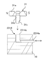
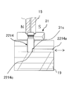
例えば、図18Aに示すように、実施形態1のセンサマグネット部31を位置決めする位置調整部2214は、可動部材2214aを備えていてもよい。可動部材2214aは、直方体である。可動部材2214aは、センサマグネット部31のピン部31bの挿入方向に対し直交する方向にスライドする。図18B及び図18Cに示すように、ピン部31bが位置調整部2214の凹部2214oに挿入されると、可動部材2214aは移動し、第2位置決め部である前面部2214cがピン部31bの第1位置決め部31cの平面部に接触する。これにより、ピン部31bの回転が阻止され、センサマグネット部31bの周方向における位置決めがされる。この例においては、位置調整部2214の凹部2214oに段部を形成する必要がないため、位置調整部2214の加工が容易である。また可動部材2214は、ピン部31bの第1位置決め部31cの平面部に対しスライド可能であるため、可動部材2214は第1位置決め部31cと隙間なく当接できる。このため、センサマグネット部31の位置決めにおいて角度誤差が生じにくく、位置決め精度を向上させる。
実施形態1のように、位置調整部21の上面は、ベース部19と面一に形成されなくてもよい。例えば、図5A及び図5Bに示すブロック体をベース部19上に形成し、同ブロック体に凹部を形成して第2位置決め部21cを設けてもよい。
上記実施形態1及び2において、オペレーション部15、152はセンサマグネット部31,231を把持していたが、これに限定されない。オペレーション部15,152は、エア吸引、磁性材による吸着等によりセンサマグネット部31、231を保持するようにしてもよい。
上記実施形態1及び2においては、メインマグネット35の極数は8としていたが、これよりも多くても少なくてもよい。また、上記の実施形態では、三相モータであるが、モータは、5相や7相等の他の相数のモータであってもよい。
上記実施形態1及び2における位置決め動作の実行順序は、必ずしも、上記実施形態1及び2の記載に制限されるものではなく、発明の要旨を逸脱しない範囲で、並行して実行したり、実行順序を入れ替えたりすることができる。
上記実施形態においては、ロータ34の固定は電気的に行うがこれに限定されない。例えば、物理的な固定部によってロータ34をロックし固定することも可能である。
上記の製造方法により製造されたモータは、例えば、電動パワーステアリング、コンプレッサ等の様々な用途に用いることができる。
10…モータ製造装置、11…アーム部、13…支持部材、15,152…オペレーション部、21,211,213,214,215,221,2211,2212,2213,2214…位置調整部、21c,211c,221c,2211c,2212c,2213c,2214c…第2位置決め部、21o,211o,213o,214o,215o,2214o…凹部、30,230…モータ、31,231,311,312,313,314,315,2311,2312,2313…センサマグネット部、31a,231a…マグネット部、31b…ピン部、31c,231c,311c,312c,313d,314d,315d,2311c,2312c,2313c…第1位置決め部、32…励磁コイル、33,233…シャフト、33a…凹部、34…ロータ、35…メインマグネット、36…ステータ、50…制御部、213d,214d,215d…突出部、221b,2211b,2212b,2213b…ホルダ支持部、231b…ホルダ部、231f,2311f,2313f…フランジ部、2214a…可動部材
Claims (20)
- 励磁コイルを含むステータと、
シャフト及びメインマグネットを有し、前記ステータの径方向内側に回転可能に設けられるロータと、
前記ロータの回転位置を検出するためのセンサマグネット部と、を備えるモータの製造方法であって、
前記メインマグネットが第1回転位置に位置する状態で前記ロータを固定する工程と、
位置決め装置を用いて、前記センサマグネット部を、前記シャフトの軸と平行な軸に沿って位置決めするとともに、前記第1回転位置に対し所定の角度を有する第2回転位置に位置決めする工程と、
前記位置決め装置により位置決めされたセンサマグネット部を前記シャフトに取り付ける工程と、を含む、モータの製造方法。 - 前記センサマグネット部を位置決めする工程は、前記センサマグネット部に設けられた第1位置決め部と前記位置決め装置に設けられた第2位置決め部とを係合させる工程を含む、請求項1に記載のモータの製造方法。
- 前記センサマグネット部は、磁極を有するマグネット部と前記マグネット部を取り付けたピン部とを含み、
前記シャフトは、内部に軸方向に延びる凹部を含み、
前記センサマグネット部を前記シャフトに取り付ける工程は、前記センサマグネット部のピン部を前記シャフトの前記凹部内に圧入する工程を含む、請求項1又は2に記載のモータの製造方法。 - 前記センサマグネット部は、磁極を有するマグネット部と、前記マグネット部を保持するホルダ部とを含み、
前記ホルダ部は、筒状部を含み、
前記センサマグネット部を前記シャフトに取り付ける工程は、前記センサマグネット部の前記ホルダ部の前記筒状部内に、前記シャフトの軸方向端部を圧入する工程を含む、請求項1又は2に記載のモータの製造方法。 - 前記位置決め装置は、前記シャフトの軸に平行な軸に沿って前記センサマグネットを保持可能な位置調整部と、前記センサマグネット部を保持し移動させるオペレーション部とを含み、
前記オペレーション部により前記センサマグネット部を前記位置調整部に移動し、
前記オペレーション部により前記センサマグネット部を前記位置調整部に係合させることにより前記第2回転位置に前記センサマグネット部を位置決めし、
前記オペレーション部により、前記第2回転位置に前記センサマグネット部を保持した状態で、前記センサマグネット部を前記シャフトに取り付ける、請求項1から4のいずれかに記載のモータの製造方法。 - 前記センサマグネット部は、磁極を有するマグネット部と前記マグネット部を取り付けたピン部とを含み、
前記マグネット部又は前記ピン部は、前記第1位置決め部を含み、
前記位置決め装置は、前記ピン部を収容する凹部又は前記マグネット部を支持する支持部と、を含み、
前記凹部又は前記支持部は、前記第2位置決め部を含み、
前記ピン部を前記凹部に挿入することにより前記第1位置決め部と前記第2位置決め部とを係合させる、請求項2に記載のモータの製造方法。 - 前記第1位置決め部は、Dカット加工形状、スリット、段部、突起、又は穴である、請求項6に記載のモータの製造方法。
- 前記センサマグネット部は、磁極を有するマグネット部と前記マグネット部を保持するホルダ部とを含み、
前記ホルダ部は、筒状部を含み、かつ、前記センサマグネット部の径方向外側に突出するフランジ部を有し、
前記フランジ部は、前記第1位置決め部を含み、
前記位置決め装置は、前記センサマグネット部の前記ホルダ部の前記筒状部を支持するホルダ支持部と、前記第1位置決め部と係合する第2位置決め部とを含み、
前記ホルダ支持部を前記ホルダ部の前記筒状部内に挿入し、前記第1位置決め部と前記第2位置決め部とを係合させる、請求項2に記載のモータの製造方法。 - 前記第1位置決め部は、切り欠き、曲げ加工形状、穴、又は突起である、請求項8に記載のモータの製造方法。
- 励磁コイルを含むステータと、
前記ステータの径方向内側に回転可能に設けられ、回転するシャフトと、前記シャフトとともに回転するメインマグネット部と、を含むロータと、
前記ロータの回転位置を検出するためのセンサマグネット部と、を備えるモータのセンサマグネット部の位置決め装置であって、
前記シャフトの軸に平行な軸に沿って前記センサマグネット部を位置決めするとともに、前記センサマグネット部に設けられた第1位置決め部に係合可能な第2位置決め部を有する位置調整部と、
前記第1位置決め部と前記第2位置決め部とを係合させることにより前記センサマグネット部を所定の回転位置に位置決めし、位置決めされた前記センサマグネットを前記シャフトに取り付けるオペレーション部と、を備える、センサマグネット部の位置決め装置。 - 前記センサマグネット部は、磁極を有するマグネット部と、前記マグネット部を取り付けたピン部とを含み、
前記マグネット部又は前記ピン部は、前記第1位置決め部を含み、
前記位置調整部は、前記第1位置決め部と係合可能な形状を有する第2位置決め部を含む、請求項10に記載のセンサマグネット部の位置決め装置。 - 前記第1位置決め部は、Dカット加工形状、スリット、段部、突起、又は穴である、請求項11に記載のセンサマグネット部の位置決め装置。
- 前記センサマグネット部は、磁極を有するマグネット部と前記マグネット部を保持するホルダ部とを含み、前記ホルダ部は、筒状部を含み、かつ、前記センサマグネット部の径方向外側に突出し第1位置決め部を有するフランジ部を含み、
前記位置調整部は、前記第1位置決め部と係合可能な形状を有する第2位置決め部を含む、請求項10に記載のセンサマグネット部の位置決め装置。 - 前記第1位置決め部は、切り欠き、曲げ加工形状、穴、又は突起である、請求項13に記載のセンサマグネット部の位置決め装置。
- 励磁コイルを含むステータと、
軸方向端部の軸心を中心とする真円状の凹部を有するシャフト及びメインマグネットを有し、前記ステータの径方向内側に回転可能に設けられるロータと、
前記シャフトに取り付けられ、前記ロータの回転位置を検出するためのセンサマグネット部と、
前記センサマグネット部に形成され、前記メインマグネットの所定の回転位置に対して所定の角度を有する回転位置に前記センサマグネットを位置決めする第1位置決め部と、を備えるモータ。 - 前記センサマグネット部は、磁極を有するマグネット部と前記マグネット部を取り付けたピン部とを含み、
前記シャフトは、内部に軸方向に延びる凹部を含み、
前記センサマグネット部は、前記ピン部を前記シャフトの前記凹部内に圧入することにより前記シャフトに固定される、請求項15に記載のモータ。 - 前記マグネット部又は前記ピン部は、前記第1位置決め部を含み、
前記第1位置決め部は、Dカット加工形状、スリット、段部、突起、又は穴である、請求項16に記載のモータ。 - 前記センサマグネット部は、磁極を有するマグネット部と、前記マグネット部を保持するホルダ部とを含み、
前記ホルダ部は、筒状部を含み、
前記センサマグネット部は、前記ホルダ部の筒状部内に前記シャフトの軸方向端部を圧入される、請求項15に記載のモータ。 - 前記ホルダ部は、前記センサマグネット部の径方向外側に突出するフランジ部を有し、
前記フランジ部は、前記第1位置決め部を含み、
前記第1位置決め部は、切り欠き、曲げ形状、穴、又は突起である、請求項18に記載のモータ。 - 励磁コイルを含むステータと、
前記ステータの径方向内側に回転可能に設けられ、回転するシャフトと、前記シャフトとともに回転するメインマグネットと、を含むロータと、
前記ロータの回転位置を検出するためのセンサマグネット部と、を備えるモータの製造装置であって、
前記メインマグネットが第1回転位置に位置する状態で前記ロータを固定する固定部と、
前記シャフトの軸に平行な軸に沿って前記センサマグネット部を位置決めするとともに、前記第1回転位置に対し所定の角度を有する第2回転位置に前記センサマグネット部を位置決めする位置調整部と、
前記位置調整部により位置決めされたセンサマグネット部を前記シャフトに取り付けるオペレーション部と、
前記オペレーション部の動作を制御する制御部と、を備える、モータの製造装置。
Priority Applications (1)
| Application Number | Priority Date | Filing Date | Title |
|---|---|---|---|
| CN201880042233.4A CN110785916B (zh) | 2017-06-30 | 2018-04-05 | 马达的制造方法、传感器磁铁部的定位装置、马达以及马达制造装置 |
Applications Claiming Priority (2)
| Application Number | Priority Date | Filing Date | Title |
|---|---|---|---|
| JP2017129548 | 2017-06-30 | ||
| JP2017-129548 | 2017-06-30 |
Publications (1)
| Publication Number | Publication Date |
|---|---|
| WO2019003552A1 true WO2019003552A1 (ja) | 2019-01-03 |
Family
ID=64741548
Family Applications (1)
| Application Number | Title | Priority Date | Filing Date |
|---|---|---|---|
| PCT/JP2018/014545 Ceased WO2019003552A1 (ja) | 2017-06-30 | 2018-04-05 | モータの製造方法、センサマグネット部の位置決め装置、モータ、及びモータ製造装置 |
Country Status (2)
| Country | Link |
|---|---|
| CN (1) | CN110785916B (ja) |
| WO (1) | WO2019003552A1 (ja) |
Citations (3)
| Publication number | Priority date | Publication date | Assignee | Title |
|---|---|---|---|---|
| JP2003209953A (ja) * | 2002-01-11 | 2003-07-25 | Matsushita Electric Ind Co Ltd | センサー付モータの組立方法 |
| JP2009284658A (ja) * | 2008-05-22 | 2009-12-03 | Asmo Co Ltd | ロータ及びモータ |
| JP2013240251A (ja) * | 2012-05-17 | 2013-11-28 | Asmo Co Ltd | 回転伝達装置、回転伝達装置の製造方法及びモータ |
Family Cites Families (6)
| Publication number | Priority date | Publication date | Assignee | Title |
|---|---|---|---|---|
| JP2009100531A (ja) * | 2007-10-16 | 2009-05-07 | Mabuchi Motor Co Ltd | インナーロータブラシレスモータ及びその製造方法 |
| EP2141785B1 (en) * | 2008-07-04 | 2019-08-28 | Mabuchi Motor Co., Ltd. | Sensor magnet holder, motor having the holder incorporated therein, and method of manufacturing the motor |
| CN101789672A (zh) * | 2010-03-26 | 2010-07-28 | 江门市蒙德电气有限公司 | 一种电动门电机用磁编码器 |
| EP3121943B1 (en) * | 2014-03-19 | 2018-09-05 | Mitsubishi Electric Corporation | Electric motor and electric power steering device using same |
| DE102015002562B4 (de) * | 2015-02-27 | 2019-02-14 | Brose Fahrzeugteile GmbH & Co. Kommanditgesellschaft, Würzburg | Elektrische Maschine |
| JP2017009312A (ja) * | 2015-06-17 | 2017-01-12 | 株式会社ジェイテクト | 回転角センサ、それを備えたモータ装置および回転角センサの製造方法 |
-
2018
- 2018-04-05 WO PCT/JP2018/014545 patent/WO2019003552A1/ja not_active Ceased
- 2018-04-05 CN CN201880042233.4A patent/CN110785916B/zh not_active Expired - Fee Related
Patent Citations (3)
| Publication number | Priority date | Publication date | Assignee | Title |
|---|---|---|---|---|
| JP2003209953A (ja) * | 2002-01-11 | 2003-07-25 | Matsushita Electric Ind Co Ltd | センサー付モータの組立方法 |
| JP2009284658A (ja) * | 2008-05-22 | 2009-12-03 | Asmo Co Ltd | ロータ及びモータ |
| JP2013240251A (ja) * | 2012-05-17 | 2013-11-28 | Asmo Co Ltd | 回転伝達装置、回転伝達装置の製造方法及びモータ |
Also Published As
| Publication number | Publication date |
|---|---|
| CN110785916A (zh) | 2020-02-11 |
| CN110785916B (zh) | 2022-02-22 |
Similar Documents
| Publication | Publication Date | Title |
|---|---|---|
| US9692270B2 (en) | Motor including brackets and fixing members | |
| CN101960697B (zh) | 无刷马达 | |
| JP3146492B2 (ja) | ブラシレスdcモータ | |
| US11283309B2 (en) | Brushless motor and winding method for stator | |
| US6812611B2 (en) | Permanent magnet type electric rotating machine | |
| JPWO2005099068A1 (ja) | ブラシレスモータ | |
| CN112640260B (zh) | 电动马达 | |
| JP2007267565A (ja) | コアレスモータ | |
| JP2020048268A (ja) | 電動モータおよび電動モータの製造方法 | |
| JP2009284706A (ja) | ロータ、およびブラシレスモータ | |
| EP3306784B1 (en) | Brushless motor and winding method for stator | |
| JP6504261B2 (ja) | 電動機の回転子の製造方法及び製造装置 | |
| CN108475947B (zh) | 定子、马达以及定子的制造方法 | |
| JP2007181377A (ja) | モータの製造方法及びモータ | |
| CN110785916B (zh) | 马达的制造方法、传感器磁铁部的定位装置、马达以及马达制造装置 | |
| CN110809850B (zh) | 马达的制造方法、马达制造装置以及传感器磁铁部的定位装置 | |
| WO2019003551A1 (ja) | モータ製造装置及びモータの製造方法 | |
| JP4549813B2 (ja) | ステータ及びブラシレスモータ | |
| JP2008151527A (ja) | レゾルバロータの取付方法 | |
| CN205647223U (zh) | 马达 | |
| JP4971417B2 (ja) | ステータ及びブラシレスモータ | |
| JP2008220114A (ja) | レゾルバホルダ、及びブラシレスモータ | |
| JP2007006621A (ja) | 回転機及びその製造方法 | |
| JP2006271093A (ja) | 分割コア式モータのステータ組み付け方法および組み付け用治具 | |
| CN111953114B (zh) | 定子、马达以及送风装置 |
Legal Events
| Date | Code | Title | Description |
|---|---|---|---|
| 121 | Ep: the epo has been informed by wipo that ep was designated in this application |
Ref document number: 18825410 Country of ref document: EP Kind code of ref document: A1 |
|
| NENP | Non-entry into the national phase |
Ref country code: DE |
|
| 122 | Ep: pct application non-entry in european phase |
Ref document number: 18825410 Country of ref document: EP Kind code of ref document: A1 |
|
| NENP | Non-entry into the national phase |
Ref country code: JP |