WO2019003302A1 - Appareil de commande de véhicule - Google Patents
Appareil de commande de véhicule Download PDFInfo
- Publication number
- WO2019003302A1 WO2019003302A1 PCT/JP2017/023581 JP2017023581W WO2019003302A1 WO 2019003302 A1 WO2019003302 A1 WO 2019003302A1 JP 2017023581 W JP2017023581 W JP 2017023581W WO 2019003302 A1 WO2019003302 A1 WO 2019003302A1
- Authority
- WO
- WIPO (PCT)
- Prior art keywords
- vehicle
- follow
- variable
- control device
- generation unit
- Prior art date
Links
- 230000001133 acceleration Effects 0.000 claims description 51
- 238000001514 detection method Methods 0.000 claims description 23
- 238000012545 processing Methods 0.000 claims description 11
- 230000036461 convulsion Effects 0.000 claims description 4
- 238000010586 diagram Methods 0.000 description 33
- 230000006399 behavior Effects 0.000 description 30
- 230000008859 change Effects 0.000 description 13
- 230000007774 longterm Effects 0.000 description 12
- 238000000034 method Methods 0.000 description 9
- 238000011156 evaluation Methods 0.000 description 8
- 230000004043 responsiveness Effects 0.000 description 8
- 230000004044 response Effects 0.000 description 5
- 230000003068 static effect Effects 0.000 description 5
- 230000008901 benefit Effects 0.000 description 4
- 238000004891 communication Methods 0.000 description 4
- 238000013459 approach Methods 0.000 description 3
- 230000003111 delayed effect Effects 0.000 description 3
- 238000013016 damping Methods 0.000 description 2
- 238000013461 design Methods 0.000 description 2
- 230000033001 locomotion Effects 0.000 description 2
- 238000005457 optimization Methods 0.000 description 2
- 230000009471 action Effects 0.000 description 1
- 230000003044 adaptive effect Effects 0.000 description 1
- 230000005540 biological transmission Effects 0.000 description 1
- 230000000052 comparative effect Effects 0.000 description 1
- 239000002131 composite material Substances 0.000 description 1
- 230000010485 coping Effects 0.000 description 1
- 230000000694 effects Effects 0.000 description 1
- 238000012854 evaluation process Methods 0.000 description 1
- 238000003384 imaging method Methods 0.000 description 1
- 238000012423 maintenance Methods 0.000 description 1
- 239000000203 mixture Substances 0.000 description 1
- 239000000523 sample Substances 0.000 description 1
- 239000013589 supplement Substances 0.000 description 1
- 230000002194 synthesizing effect Effects 0.000 description 1
Images


Classifications
-
- B—PERFORMING OPERATIONS; TRANSPORTING
- B60—VEHICLES IN GENERAL
- B60W—CONJOINT CONTROL OF VEHICLE SUB-UNITS OF DIFFERENT TYPE OR DIFFERENT FUNCTION; CONTROL SYSTEMS SPECIALLY ADAPTED FOR HYBRID VEHICLES; ROAD VEHICLE DRIVE CONTROL SYSTEMS FOR PURPOSES NOT RELATED TO THE CONTROL OF A PARTICULAR SUB-UNIT
- B60W30/00—Purposes of road vehicle drive control systems not related to the control of a particular sub-unit, e.g. of systems using conjoint control of vehicle sub-units
- B60W30/14—Adaptive cruise control
- B60W30/16—Control of distance between vehicles, e.g. keeping a distance to preceding vehicle
- B60W30/165—Automatically following the path of a preceding lead vehicle, e.g. "electronic tow-bar"
-
- B—PERFORMING OPERATIONS; TRANSPORTING
- B60—VEHICLES IN GENERAL
- B60W—CONJOINT CONTROL OF VEHICLE SUB-UNITS OF DIFFERENT TYPE OR DIFFERENT FUNCTION; CONTROL SYSTEMS SPECIALLY ADAPTED FOR HYBRID VEHICLES; ROAD VEHICLE DRIVE CONTROL SYSTEMS FOR PURPOSES NOT RELATED TO THE CONTROL OF A PARTICULAR SUB-UNIT
- B60W50/00—Details of control systems for road vehicle drive control not related to the control of a particular sub-unit, e.g. process diagnostic or vehicle driver interfaces
- B60W50/0097—Predicting future conditions
-
- B—PERFORMING OPERATIONS; TRANSPORTING
- B60—VEHICLES IN GENERAL
- B60W—CONJOINT CONTROL OF VEHICLE SUB-UNITS OF DIFFERENT TYPE OR DIFFERENT FUNCTION; CONTROL SYSTEMS SPECIALLY ADAPTED FOR HYBRID VEHICLES; ROAD VEHICLE DRIVE CONTROL SYSTEMS FOR PURPOSES NOT RELATED TO THE CONTROL OF A PARTICULAR SUB-UNIT
- B60W30/00—Purposes of road vehicle drive control systems not related to the control of a particular sub-unit, e.g. of systems using conjoint control of vehicle sub-units
- B60W30/14—Adaptive cruise control
- B60W30/16—Control of distance between vehicles, e.g. keeping a distance to preceding vehicle
- B60W30/162—Speed limiting therefor
-
- B—PERFORMING OPERATIONS; TRANSPORTING
- B60—VEHICLES IN GENERAL
- B60W—CONJOINT CONTROL OF VEHICLE SUB-UNITS OF DIFFERENT TYPE OR DIFFERENT FUNCTION; CONTROL SYSTEMS SPECIALLY ADAPTED FOR HYBRID VEHICLES; ROAD VEHICLE DRIVE CONTROL SYSTEMS FOR PURPOSES NOT RELATED TO THE CONTROL OF A PARTICULAR SUB-UNIT
- B60W2554/00—Input parameters relating to objects
- B60W2554/40—Dynamic objects, e.g. animals, windblown objects
- B60W2554/404—Characteristics
- B60W2554/4041—Position
-
- B—PERFORMING OPERATIONS; TRANSPORTING
- B60—VEHICLES IN GENERAL
- B60W—CONJOINT CONTROL OF VEHICLE SUB-UNITS OF DIFFERENT TYPE OR DIFFERENT FUNCTION; CONTROL SYSTEMS SPECIALLY ADAPTED FOR HYBRID VEHICLES; ROAD VEHICLE DRIVE CONTROL SYSTEMS FOR PURPOSES NOT RELATED TO THE CONTROL OF A PARTICULAR SUB-UNIT
- B60W2554/00—Input parameters relating to objects
- B60W2554/40—Dynamic objects, e.g. animals, windblown objects
- B60W2554/404—Characteristics
- B60W2554/4046—Behavior, e.g. aggressive or erratic
-
- B—PERFORMING OPERATIONS; TRANSPORTING
- B60—VEHICLES IN GENERAL
- B60W—CONJOINT CONTROL OF VEHICLE SUB-UNITS OF DIFFERENT TYPE OR DIFFERENT FUNCTION; CONTROL SYSTEMS SPECIALLY ADAPTED FOR HYBRID VEHICLES; ROAD VEHICLE DRIVE CONTROL SYSTEMS FOR PURPOSES NOT RELATED TO THE CONTROL OF A PARTICULAR SUB-UNIT
- B60W2554/00—Input parameters relating to objects
- B60W2554/80—Spatial relation or speed relative to objects
- B60W2554/802—Longitudinal distance
-
- B—PERFORMING OPERATIONS; TRANSPORTING
- B60—VEHICLES IN GENERAL
- B60W—CONJOINT CONTROL OF VEHICLE SUB-UNITS OF DIFFERENT TYPE OR DIFFERENT FUNCTION; CONTROL SYSTEMS SPECIALLY ADAPTED FOR HYBRID VEHICLES; ROAD VEHICLE DRIVE CONTROL SYSTEMS FOR PURPOSES NOT RELATED TO THE CONTROL OF A PARTICULAR SUB-UNIT
- B60W2720/00—Output or target parameters relating to overall vehicle dynamics
- B60W2720/10—Longitudinal speed
-
- B—PERFORMING OPERATIONS; TRANSPORTING
- B60—VEHICLES IN GENERAL
- B60W—CONJOINT CONTROL OF VEHICLE SUB-UNITS OF DIFFERENT TYPE OR DIFFERENT FUNCTION; CONTROL SYSTEMS SPECIALLY ADAPTED FOR HYBRID VEHICLES; ROAD VEHICLE DRIVE CONTROL SYSTEMS FOR PURPOSES NOT RELATED TO THE CONTROL OF A PARTICULAR SUB-UNIT
- B60W2754/00—Output or target parameters relating to objects
- B60W2754/10—Spatial relation or speed relative to objects
- B60W2754/30—Longitudinal distance
Definitions
- the present invention relates to a vehicle control device that automatically performs at least partial travel control of a host vehicle.
- a vehicle control device that performs traveling control of a host vehicle at least partially automatically is known.
- various driving support techniques or automatic driving techniques have been developed for causing the vehicle to travel smoothly while considering the relationship with the preceding other vehicle.
- the present invention has been made to solve the above-described problems, and provides a vehicle control device capable of coping with the change with high responsiveness even if the traveling behavior of the preceding other vehicle changes sharply.
- the purpose is to
- the vehicle control device is a device that automatically performs traveling control of the own vehicle at least partially, and an external world state detection unit that detects the external world state of the own vehicle, and the external world condition detection unit
- the vehicle control system further includes: a traveling control unit capable of executing follow-up control on another vehicle detected in front of the vehicle; and a follow-up variable generation unit generating a follow-up variable related to the follow-up control. Calculating a predicted position of the other vehicle at the predicted time point of the vehicle, setting a target position that is ahead of the predicted position by the target inter-vehicle distance, and setting a first follow-up variable for causing the vehicle to reach the target position at the predicted time point decide.
- the target position which is ahead of the predicted position of the other vehicle by the target inter-vehicle distance is set, and the first follow-up variable for causing the vehicle to reach the target position at the predicted time ahead of the current time is determined. It is possible to perform follow-up control that secures an inter-vehicle distance equal to the target inter-vehicle distance at a specific point in time in the future regardless of the traveling behavior. As a result, even if the traveling behavior of the preceding other vehicle changes suddenly, it is possible to cope with the change with high responsiveness.
- the follow-up variable generation unit determines a second follow-up variable based on a vehicle behavior model different from the first follow-up variable, and performs arithmetic processing in which at least the first follow-up variable and the second follow-up variable are input.
- the following variable may be generated by performing. This makes it possible to blend two different responses depending on the vehicle behavior model, and increases the flexibility of optimization design for follow-up control.
- the follow-up variable generation unit may determine the second follow-up variable based on a spring mass damper model as the vehicle behavior model.
- the spring-mass-damper model has an advantage that when the host vehicle approaches another vehicle from a distance greater than the target inter-vehicle distance, the response to cope with the other vehicle is relatively high. That is, it is possible to perform follow-up control incorporating this advantage.
- the follow-up variable generation unit may generate the follow-up variable by performing minimum value calculation processing.
- the follow-up variable generation unit may generate the follow-up variable by performing the arithmetic processing different depending on a traveling scene of the host vehicle.
- the follow-up variable generation unit may generate, as the follow-up variable, at least one of the speed, the acceleration, and the jerk of the host vehicle.
- the vehicle control device even when the traveling behavior of the preceding other vehicle changes rapidly, the change can be dealt with with high responsiveness.
- FIG. 3 is a detailed block diagram of a target speed generator shown in FIG. 2; It is a detailed block diagram of the restriction
- 8A to 8D are diagrams showing the results of performing follow-up control based on a spring mass damper model.
- 9A to 9D are diagrams showing the results of performing follow-up control based on the inter-vehicle preview model and the spring mass damper model.
- 10A to 10D are diagrams showing the results of performing follow-up control based on the inter-vehicle preview model.
- 11A to 11D are diagrams showing the results of performing follow-up control based on the inter-vehicle preview model and the spring mass damper model.
- 12A to 12C are diagrams showing the results of performing follow-up control based on the inter-vehicle preview model and the spring mass damper model.
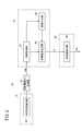
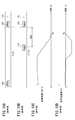
- FIG. 1 is a block diagram showing the configuration of a vehicle control device 10 according to an embodiment of the present invention.
- the vehicle control device 10 is incorporated in a vehicle (the vehicle 110 shown in FIG. 5), and performs travel control of the vehicle automatically or manually.
- This "automatic driving” is a concept including “partial automatic driving” (or driving assistance) that partially automatically performs traveling control, as well as “completely automatic driving” in which all traveling control of the vehicle is automatically performed. .
- the vehicle control device 10 basically includes an input system device group, a control system 12, and an output system device group.
- the respective devices forming the input system device group and the output system device group are connected to the control system 12 via a communication line.
- the input system device group includes an external sensor 14, a communication device 16, a navigation device 18, a vehicle sensor 20, an automatic driving switch 22, and an operation detection sensor 26 connected to the operation device 24.
- the output system group includes a driving force device 28 for driving a wheel, a steering device 30 for steering the wheel, and a braking device 32 for braking the wheel.
- the external world sensor 14 includes a plurality of cameras 33 and a plurality of radars 34 that acquire information indicating the external world state of the vehicle (hereinafter referred to as the external world information), and outputs the acquired external world information to the control system 12.
- the external sensor 14 may further include a plurality of LIDARs (Light Detection and Ranging) and laser imaging detection and Ranging.
- the communication device 16 is configured to be communicable with an external device including a roadside machine, another vehicle, and a server, and transmits and receives, for example, information related to traffic equipment, information related to other vehicles, probe information or latest map information. .
- the map information is stored in the navigation device 18 and is also stored in the map information storage unit 42 of the storage device 40 as the map information.
- the navigation device 18 includes a satellite positioning device capable of detecting the current position of the vehicle, and a user interface (for example, a touch panel display, a speaker and a microphone).
- the navigation device 18 calculates the route to the designated destination based on the current position of the vehicle or the designated position by the user, and outputs it to the control system 12.
- the route calculated by the navigation device 18 is stored in the route information storage unit 44 of the storage device 40 as route information.
- the vehicle sensor 20 is a velocity sensor that detects the velocity (vehicle speed) of the vehicle, a so-called longitudinal acceleration sensor that detects longitudinal acceleration, a so-called lateral acceleration sensor that detects transverse acceleration, a yaw rate sensor that detects angular velocity around the vertical axis, It includes an orientation sensor that detects an orientation, and a gradient sensor that detects a gradient, and outputs detection signals from each sensor to the control system 12. These detection signals are stored in the vehicle state information storage unit 46 of the storage device 40 as the vehicle state information Ivh.
- the operating device 24 is configured to include an accelerator pedal, a steering wheel, a brake pedal, a shift lever, and a direction indication lever.
- the operation device 24 is attached with an operation detection sensor 26 for detecting the presence or absence and the amount of operation of the driver and the operation position.
- the operation detection sensor 26 outputs an accelerator depression amount (accelerator opening degree), a steering wheel operation amount (steering amount), a brake depression amount, a shift position, a turning direction, etc. to the travel control unit 60 as a detection result.
- the automatic operation switch 22 is configured by a hard switch or a soft switch, and is configured to be able to switch between a plurality of operation modes including an “automatic operation mode” and a “manual operation mode” by a user's manual operation.
- the automatic driving mode is a driving mode in which the vehicle travels under the control of the control system 12 in a state where the driver does not operate the operation device 24 (specifically, the accelerator pedal, the steering wheel, and the brake pedal).
- the driving system 28, the steering system 30, and the braking system 32 are controlled based on an action plan (short-term trajectory St described later in the short term) which is sequentially determined by the control system 12. It is an operation mode which controls a part or all.
- the driving force device 28 includes a driving force control ECU (Electronic Control Unit) and a driving source including an engine and a driving motor.
- the driving force device 28 generates traveling driving force (torque) for the vehicle to travel in accordance with the vehicle control value Cvh input from the traveling control unit 60, and transmits it to the wheels via the transmission or directly.
- the steering device 30 is configured of an EPS (Electric Power Steering System) ECU and an EPS device. Steering device 30 changes the direction of the wheels (steering wheels) according to a vehicle control value Cvh input from travel control unit 60.
- EPS Electrical Power Steering System
- the braking device 32 is, for example, an electric servo brake that uses a hydraulic brake in combination, and includes a braking force control ECU and a brake actuator.
- the braking device 32 brakes the wheels according to the vehicle control value Cvh input from the traveling control unit 60.
- the function realizing unit of the control system 12 realizes functions by causing one or more CPUs (Central Processing Units) to execute a program stored in a non-transitory storage medium (for example, the storage device 40).
- Software functional unit may be a hardware function unit formed of an integrated circuit such as an FPGA (Field-Programmable Gate Array).
- the control system 12 includes an external world recognition unit 52, a recognition result reception unit 53, a local environment map generation unit 54, a general control unit 70, and a long-term trajectory generation unit 71, in addition to the storage device 40 and the travel control unit 60.
- a medium-term trajectory generation unit 72 and a short-term trajectory generation unit 73 are included.
- the general control unit 70 controls the task synchronization of the recognition result reception unit 53, the local environment map generation unit 54, the long-term trajectory generation unit 71, the medium-term trajectory generation unit 72, and the short-term trajectory generation unit 73. Perform integrated control of
- the external world recognition unit 52 refers to the vehicle state information Ivh from the traveling control unit 60, and then uses various information (for example, external world information from the external world sensor 14) input by the input system device group to make a lane mark. -After recognizing a sign such as a stop line or a traffic light, "static" external recognition information including position information of the sign or a travelable area of the vehicle is generated. In addition, the external world recognition unit 52 uses the input various information to input “dynamic” external world recognition information including an obstacle such as a parked vehicle, a traffic participant such as a person or another vehicle, or a light color of a traffic light Generate
- the static and dynamic external world recognition information is stored in the external world recognition information storage unit 45 of the storage device 40 as the external world recognition information Ipr.
- the recognition result receiving unit 53 In response to the calculation command Aa, the recognition result receiving unit 53 outputs the external world recognition information Ipr received within a predetermined calculation cycle Toc to the general control unit 70 together with the count value of the update counter.
- the calculation cycle Toc is a reference calculation cycle inside the control system 12, and is set to, for example, a value of about several tens of ms.
- Local environment map generation unit 54 generates local environment map information Iem within the operation cycle Toc with reference to the vehicle state information Ivh and the external world recognition information Ipr in response to the operation command Ab from the general control unit 70. , And the count value of the update counter are output to the general control unit 70. That is, at the start of control, it takes 2 ⁇ Toc to calculate local environment map information Iem.
- the local environment map information Iem is information in which the traveling environment of the vehicle is mapped, and roughly formed by synthesizing the vehicle state information Ivh and the ideal traveling route with the external world recognition information Ipr.
- the local environment map information Iem is stored in the local environment map information storage unit 47 of the storage device 40.
- the long-term trajectory generation unit 71 responds to the calculation command Ac from the general control unit 70, and local environment map information Iem (use only static components of the external world recognition information Ipr), vehicle state information Ivh, and map information With reference to a road map (curvature of a curve or the like) stored in the storage unit 42, a long-term trajectory Lt is generated with a relatively long operation cycle (for example, 9 ⁇ Toc). Then, the long-term trajectory generation unit 71 outputs the generated long-term trajectory Lt to the general control unit 70 together with the count value of the update counter.
- the long-term trajectory Lt is stored in the trajectory information storage unit 48 of the storage device 40 as the trajectory information Ir.
- the mid-term trajectory generation unit 72 responds to the operation command Ad from the general control unit 70, and generates local environment map information Iem (uses both the dynamic component and the static component of the external world recognition information Ipr), With reference to the vehicle state information Ivh and the long-term orbit Lt, the medium-term orbit Mt is generated with a relatively medium operation cycle (for example, 3 ⁇ Toc). Then, the mid-term trajectory generation unit 72 outputs the generated mid-term trajectory Mt to the general control unit 70 together with the count value of the update counter.
- the medium-term orbit Mt is stored in the orbit information storage unit 48 of the storage device 40 as the orbit information Ir, similarly to the long-term orbit Lt.
- the short-term trajectory generation unit 73 responds to the operation command Ae from the general control unit 70 to generate local environment map information Iem (using both dynamic and static components of the external world recognition information Ipr), With reference to the vehicle state information Ivh and the mid-term track Mt, the short-term track St is generated with the relatively shortest operation cycle (for example, Toc). The short-term track generation unit 73 simultaneously outputs the generated short-term track St to the general control unit 70 and the travel control unit 60 together with the count value of the update counter.
- the short-term orbit St is stored in the orbit information storage unit 48 as the orbit information Ir, similarly to the long-term orbit Lt and the middle-term orbit Mt.
- the long-term track Lt indicates a track at a traveling time of, for example, about 10 seconds, and is a track giving priority to ride comfort and comfort.
- the short-term track St indicates a track at a traveling time of, for example, about one second, and is a track giving priority to the realization of vehicle dynamics and the level of safety.
- the middle track Ort indicates a track at a traveling time of, for example, about 5 seconds, and is an intermediate track with respect to the long track Lt and the short track St.
- the short-term track St includes, for example, position x in the longitudinal direction (X axis), position y in the lateral direction (Y axis), attitude angle ⁇ z (yaw angle), velocity V, acceleration G, curvature ⁇ , yaw rate ⁇ , steering angle ⁇ st Trajectory plot (x, y, ⁇ z, V, G, ⁇ , ⁇ , ⁇ st) in which
- the long-term orbit Lt or the middle-term orbit Mt is a data set defined similarly to the short-term orbit St, although the periods are different.
- the traveling control unit 60 determines each vehicle control value Cvh for performing traveling control of the vehicle, in accordance with the traveling behavior (time series of the target behavior) specified from the short-term track St. Then, the traveling control unit 60 outputs the obtained vehicle control values Cvh to the driving force device 28, the steering device 30, and the braking device 32. That is, the traveling control unit 60 is configured to be able to execute one or more types of traveling control corresponding to each value of the short-term track St.
- ACC Adaptive Cruise Control
- follow-up travel deceleration travel
- curve travel curve travel
- obstacle avoidance travel a type of "following control" in which the other preceding vehicle is driven to follow while keeping the inter-vehicle distance substantially constant (that is, the target inter-vehicle distance).
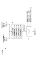
- FIG. 2 is a functional block diagram showing the main features of the vehicle control device 10 of FIG.
- the vehicle control device 10 includes an external state detection unit 80, an information acquisition unit 82, a target speed generation unit 84, a restriction application unit 86, and an acceleration / deceleration control unit 88 in addition to the local environment map generation unit 54 (FIG. 1). And.
- the external world state detection unit 80 corresponds to the external world sensor 14 shown in FIG.
- the information acquisition unit 82, the target velocity generation unit 84, and the restriction application unit 86 correspond to the short-term trajectory generation unit 73 shown in FIG.
- the acceleration / deceleration control unit 88 corresponds to the traveling control unit 60 shown in FIG.
- the external world state detection unit 80 detects the external world state of the host vehicle 110 (FIG. 5). For example, by using the camera 33, a captured image including the road 112 (FIG. 5) on which the vehicle 110 is traveling can be obtained.
- the information acquisition unit 82 acquires various types of information to be provided for the generation of the short-term trajectory St from the local environment map information Iem including the detection result of the external world state detection unit 80.
- This information includes, for example, lane mark information that can specify the shape of lane marks (lane marks 117 and 118 in FIG. 5) in addition to the above-described vehicle state information Ivh, and other vehicles (other vehicles 120 in FIG. 5). Other vehicle information that can specify position and movement is included.
- the target velocity generation unit 84 generates a short-term trajectory St indicating a time-series pattern of the target velocity, using the various information acquired by the information acquisition unit 82.
- the restriction giving unit 86 sets a time-series pattern of speed limit (hereinafter, speed limit pattern) using various information acquired by the information acquisition unit 82, and outputs the time series pattern toward the target speed generation unit 84. That is, the restriction giving unit 86 restricts the traveling behavior (here, the speed) of the host vehicle 110 by reflecting the restriction speed on the generation of the short-term track St.
- the acceleration / deceleration control unit 88 performs acceleration control or deceleration control on the host vehicle 110 to match the target velocity generated by the target velocity generation unit 84. Specifically, the acceleration / deceleration control unit 88 outputs the speed pattern (vehicle control value Cvh) indicated by the short-term track St to the driving force device 28 or the braking device 32.
- FIG. 3 is a detailed block diagram of the target speed generation unit 84 shown in FIG.
- the target velocity generation unit 84 includes a pattern generation unit 91, a trajectory candidate generation unit 92, a trajectory evaluation unit 93, and an output trajectory generation unit 94.
- the pattern generation unit 91 generates a variation group relating to two types of patterns to be provided for the generation of the short-term trajectory St, using the vehicle state information Ivh and the local environment map information Iem. Specifically, the pattern generation unit 91 is a variation on a velocity pattern (longitudinal pattern) indicating a time series of [1] velocity V and a steering angle pattern (horizontal pattern) indicating a time series of [2] steering angle ⁇ st. Generate each group.
- the trajectory candidate generation unit 92 generates a short-term trajectory St candidate (hereinafter simply referred to as “orbit candidate”) using the variation group of the pattern generated by the pattern generation unit 91. Specifically, the track candidate generation unit 92 generates a large number of track candidates including time-series information of the two-dimensional position (x, y) by combining the speed pattern and the steering angle pattern. If there is a short-term trajectory St (hereinafter referred to as the previous output trajectory) generated most recently, a constraint condition may be provided to achieve consistency with the trajectory.
- a short-term trajectory St hereinafter referred to as the previous output trajectory
- the trajectory evaluation unit 93 performs an evaluation process on each of the many trajectory candidates generated by the trajectory candidate generation unit 92 in accordance with a predetermined evaluation standard.
- the evaluation criteria the local environment map information Iem (including the lane mark and the detection result of the preceding vehicle) or the upper layer trajectory (middle trajectory Mt) is referred to.
- the track evaluation unit 93 can change the evaluation criteria so that the host vehicle 110 travels at a speed equal to or less than the speed limit, with reference to the speed limit pattern by the restriction application section 86 (FIG. 2).
- deviation of one or more variables constituting the trajectory plot (x, y, ⁇ z, V, G, ⁇ , ⁇ , ⁇ st) and a target value (reference value) is determined, and this deviation is scored
- a method of calculating an overall score by weighting operation For example, an evaluation result emphasizing particular parameters can be obtained by relatively increasing the weighting factor corresponding to the particular parameter.
- FIG. 4 is a detailed block diagram of the restriction giving unit 86 shown in FIG.
- the restriction giving unit 86 includes a following variable generation unit 96 and a minimum selector 98.
- the follow-up variable generation unit 96 is an ideal follow-up variable (for example, an ideal follow-up to follow the other vehicle 120 using vehicle information on the other vehicle 120 (hereinafter referred to as other vehicle information) besides the vehicle state information Ivh. Generate speed).
- the other vehicle information includes the position, velocity, acceleration, or jerk of the other vehicle 120.
- the minimum selector 98 selects the ideal tracking speed generated by the tracking variable generation unit 96 and the minimum speed among the three types of speed limit candidates A, B and C, and outputs it as a speed limit pattern.
- the speed limit candidate A is the upper limit value of the speed based on the legal regulations (so-called legal speed).
- the speed limit candidate B is an upper limit value of the speed calculated based on the lane curvature to maintain stable traveling behavior.
- the speed limit candidate C is an upper limit value of the speeds that can be stopped at a predetermined stop position, which is calculated based on the indication state of the traffic light and the stop line.
- the vehicle control device 10 in the present embodiment is configured as described above. Subsequently, the operation of the vehicle control device 10 will be described with reference to FIGS.
- FIG. 5 is a diagram showing the positional relationship between the host vehicle 110 and the other vehicle 120. As shown in FIG. The vehicle 110 travels on a road 112 which is generally straight and has three lanes on one side. On the road 112, dashed lane marks 117, 118 for marking the lanes 114, 115, 116 are marked.
- the other vehicle 120 travels on the same lane 115 while preceding the host vehicle 110.
- the traveling control unit 60 assumes that follow-up control is being performed on the other vehicle 120 preceding the host vehicle 110.
- the external world state detection unit 80 detects the lane marks 117 and 118 as stationary objects around the host vehicle 110 and detects the other vehicle 120 as moving objects around the host vehicle 110. Then, the vehicle control device 10 acquires other-vehicle information based on the detection result of the outside sensor 14 (or from the other vehicle 120 via inter-vehicle communication).
- the X axis is defined along the extending direction of the lanes 115, that is, the traveling direction of the host vehicle 110.
- a reference position (for example, a middle point position of a rear wheel axle) of the host vehicle 110 is set as an origin O.
- the roadway distance (S axis) is substantially equal to the position on the X axis.
- the inter-vehicle distance D is the distance between the front end position of the host vehicle 110 (the position of the front grille) and the rear end position of the other vehicle 120.
- the offset amount ofs is a length from the origin O to the tip position.
- the target inter-vehicle distance Dtar is an inter-vehicle distance set in advance by the inter-vehicle distance setting unit 100.
- the traveling position, the road distance, the speed, and the acceleration of the host vehicle 110 are respectively (x0, s0, v0, a0).
- the position of the other vehicle 120, the road distance, the speed, and the acceleration are respectively (x1, s1, v1, a1).
- the first acceleration determination unit 102 determines the traveling behavior (here, the first acceleration) of the host vehicle 110 based on the first vehicle behavior model.
- the first acceleration determination unit 102 uses the other vehicle information (x1, s1, v1, a1) obtained by the detection in step S1 to predict the future position of the other vehicle 120 (hereinafter referred to as “prediction”). Predict position 132). The predicted position 132 corresponds to the position of the other vehicle 120 at the time point of the preview time Tp (arbitrary positive value).
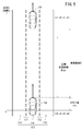
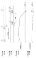
- FIG. 6 is a diagram showing a method of determining the traveling behavior by the preview inter-vehicle model.
- the horizontal axis of the graph indicates time t (unit: s), and the vertical axis of the graph indicates path distance s (unit: m).
- the prediction curve 130 is a curve indicating the prediction result of the road distance Sp (t) of the other vehicle 120.
- the path distance Sp (t) is generally expressed as the following equation (1) using an arbitrary prediction function f ( ⁇ ).
- Sp (t) f (t, s1, v1, a1) ... (1)
- the target curve 134 is a curve indicating the prediction result of the road distance Se (t) of the host vehicle 110.
- the road distance Se (t) is expressed as the following equation (2) using (s0, v0) as a known value and the acceleration ⁇ 1 (first acceleration) as an unknown value.
- Se (t) s0 + ofs + v0 ⁇ t + ⁇ 1 ⁇ t ⁇ t / 2 (2)
- the second acceleration determination unit 104 determines the traveling behavior (here, the second acceleration) of the host vehicle 110 based on the second vehicle behavior model.
- the second vehicle behavior model corresponds to a spring-mass-damper model in which the host vehicle 110 is a mass portion.
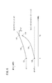
- FIG. 7 is a view showing a method of determining a traveling behavior by a spring mass damper model.
- the horizontal axis of the graph corresponds to the road distance s (unit: m).
- This model describes the positional relationship between a virtual vehicle 140 (mass M) corresponding to the vehicle 110 and a virtual other vehicle 142 corresponding to the other vehicle 120.
- a spring 144 (spring constant; k) and a damper 146 (damping coefficient; c) are provided in parallel between the virtual vehicle 140 and the virtual other vehicle 142.
- the acceleration calculation unit 106 generates a target acceleration ⁇ by performing arbitrary arithmetic processing using the accelerations ⁇ 1 and ⁇ 2 determined in steps S2 and S3, respectively. For example, the acceleration calculation unit 106 performs minimum value calculation processing to select a smaller value, and outputs any one of the accelerations ⁇ 1 and ⁇ 2 Min ( ⁇ 1 and ⁇ 2) as the target acceleration ⁇ .
- the output value of the acceleration calculation unit 106 is not limited to the minimum value, but may be any composite value including the maximum value, the average value, and the weighted average value.
- the acceleration calculation unit 106 may perform different calculation processing in accordance with the traveling scene of the host vehicle 110. For example, the acceleration calculation unit 106 may perform acceleration ⁇ 1 (or ⁇ 2) when [1] another vehicle 120 starts moving, [2] another vehicle 120 accelerates, or [3] another vehicle 120 changes lanes. You may output only
- the follow-up variable generation unit 96 integrates the target acceleration ⁇ obtained by the acceleration calculation unit 106 at time t to generate a velocity pattern, and then outputs the velocity pattern to the minimum selector 98 as an ideal follow-up velocity.
- the follow-up variable generation unit 96 generates and outputs the ideal follow-up speed of the vehicle 110, but the invention is not limited thereto. Specifically, the tracking variable generation unit 96 may generate at least one of the velocity, the acceleration, and the jerk of the vehicle 110 as the tracking variable.
- the traveling control unit 60 continues the traveling control of the vehicle 110 under the condition where the speed is limited by the limitation applying unit 86. In this manner, the host vehicle 110 follows the other vehicle 120 ahead while securing the inter-vehicle distance D equal to the target inter-vehicle distance Dtar at the prediction points set sequentially.
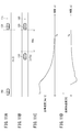
- Example 1 Tracking control based on acceleration ⁇ 2 (comparative example)> 8A to 8D are diagrams showing the results of performing follow-up control based on a spring mass damper model.
- the other vehicle 120 suddenly starts decelerating while traveling on the lane 115 while maintaining the vehicle 110 and the other vehicle 120 at a constant speed and a constant inter-vehicle distance D.
- FIG. 8C is a diagram showing a time change of the speed of the vehicle 110 (vehicle speed) in the traveling scene of FIGS. 8A and 8B.
- the horizontal axis of the graph indicates time t (unit: s), and the vertical axis of the graph indicates vehicle speed (unit: km / h).
- the definition of this graph is the same as in FIGS. 9C, 10C, and 11C described later.
- FIG. 8D is a diagram showing a time change of the acceleration (the host vehicle acceleration) of the host vehicle 110 in the traveling scene of FIGS. 8A and 8B.
- the horizontal axis of the graph indicates time t (unit: s), and the vertical axis of the graph indicates vehicle acceleration (unit: G).
- the definition of this graph is the same as in FIGS. 9D, 10D, and 11D described later.
- FIGS. 9A-9D are diagrams showing the results of performing follow-up control (minimum value calculation) based on the inter-vehicle preview model and the spring mass damper model.
- the traveling scene is the same as in FIGS. 8A-8B.
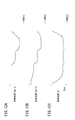
- Example 4 Tracking control based on accelerations ⁇ 1 and ⁇ 2 (Example)> 11A to 11D are diagrams showing the results of performing follow-up control (minimum value calculation) based on the inter-vehicle preview model and the spring mass damper model.
- the traveling scene is the same as in FIGS. 10A-10B.
- Example 5 Tracking Control Based on Accelerations ⁇ 1 and ⁇ 2 are diagrams showing the results of performing follow-up control (minimum value calculation) based on the inter-vehicle preview model and the spring mass damper model.
- follow-up control minimum value calculation
- FIG. 12A is a diagram showing a time change of the speed of the other vehicle 120 (the speed of the other vehicle).
- the horizontal axis of the graph indicates time t (unit: s), and the vertical axis of the graph indicates other vehicle speed (unit: km / h).
- the graph shows traveling patterns of the other vehicle 120 that sequentially perform constant speed traveling, deceleration operation, constant speed traveling, deceleration operation, constant speed traveling, and acceleration operation.
- FIG. 12B is a diagram showing a time change of the speed of the host vehicle 110 (the host vehicle speed).
- the horizontal axis of the graph indicates time t (unit: s), and the vertical axis of the graph indicates vehicle speed (unit: km / h).
- FIG. 12C is a diagram showing a time change of inter-vehicle distance D between host vehicle 110 and other vehicle 120.
- the horizontal axis of the graph indicates time t (unit: s), and the vertical axis of the graph indicates inter-vehicle distance D (unit: m).
- the host vehicle 110 performs an operation following the traveling pattern of the other vehicle 120 while always maintaining a relationship of D> Dtar.
- the vehicle control device 10 is a device that automatically performs at least partial travel control of the host vehicle 110, and [1] an external world state detection unit 80 that detects the external world state of the host vehicle 110; 2) A traveling control unit 60 capable of executing follow-up control on another vehicle 120 detected in front of the own vehicle 110, and [3] a follow-up variable generation unit 96 generating a follow-up variable related to follow-up control.
- a vehicle control method using the vehicle control device 10 is a method of automatically performing traveling control of the host vehicle 110 at least partially, and [1] detecting an external state of the host vehicle 110; 2) One or more computers execute a control step capable of executing follow-up control on another vehicle 120 detected in front of the own vehicle 110, and [3] a generation step of generating a follow-up variable related to follow-up control Do.
- the follow-up variable generation unit 96 determines a second follow-up variable (for example, acceleration ⁇ 2) based on a vehicle behavior model different from the first follow-up variable, and uses at least the first follow-up variable and the second follow-up variable as input.
- the tracking variable (target acceleration ⁇ ) may be generated by performing arithmetic processing. This makes it possible to blend two different responses depending on the vehicle behavior model, and increases the flexibility of optimization design for follow-up control.
- the follow-up variable generation unit 96 may determine the second follow-up variable based on a spring mass damper model as a vehicle behavior model.
- the spring, mass, and damper model has an advantage that the responsiveness to cope with the other vehicle 120 is relatively high when the own vehicle 110 approaches the other vehicle 120 from a distance far apart from the target inter-vehicle distance Dtar. There is. That is, it is possible to perform follow-up control incorporating this advantage.
- this invention is not limited to embodiment mentioned above, Of course, it can change freely in the range which does not deviate from the main point of this invention. Or you may combine each structure arbitrarily in the range which a technical contradiction does not arise.
Landscapes
- Engineering & Computer Science (AREA)
- Automation & Control Theory (AREA)
- Transportation (AREA)
- Mechanical Engineering (AREA)
- Human Computer Interaction (AREA)
- Control Of Driving Devices And Active Controlling Of Vehicle (AREA)
Abstract
La présente invention concerne un appareil de commande de véhicule (10) permettant de commander automatiquement au moins une partie le déplacement du véhicule hôte (110). Une unité de génération de variable suivante (96) calcule une position prédite (132) d'un autre véhicule (120) à un instant prédit avant l'instant présent, règle une position cible (136) qui est proche de la position prédite (132) selon une distance intervéhicule cible (Dtar), et détermine une première variable suivante pour amener le véhicule hôte (110) à atteindre la position cible (136) à l'instant prédit.
Priority Applications (4)
| Application Number | Priority Date | Filing Date | Title |
|---|---|---|---|
| JP2019526434A JP6868102B2 (ja) | 2017-06-27 | 2017-06-27 | 車両制御装置 |
| PCT/JP2017/023581 WO2019003302A1 (fr) | 2017-06-27 | 2017-06-27 | Appareil de commande de véhicule |
| CN201780092701.4A CN110799402B (zh) | 2017-06-27 | 2017-06-27 | 车辆控制装置 |
| US16/626,070 US11148666B2 (en) | 2017-06-27 | 2017-06-27 | Vehicle control apparatus |
Applications Claiming Priority (1)
| Application Number | Priority Date | Filing Date | Title |
|---|---|---|---|
| PCT/JP2017/023581 WO2019003302A1 (fr) | 2017-06-27 | 2017-06-27 | Appareil de commande de véhicule |
Publications (1)
| Publication Number | Publication Date |
|---|---|
| WO2019003302A1 true WO2019003302A1 (fr) | 2019-01-03 |
Family
ID=64742911
Family Applications (1)
| Application Number | Title | Priority Date | Filing Date |
|---|---|---|---|
| PCT/JP2017/023581 WO2019003302A1 (fr) | 2017-06-27 | 2017-06-27 | Appareil de commande de véhicule |
Country Status (4)
| Country | Link |
|---|---|
| US (1) | US11148666B2 (fr) |
| JP (1) | JP6868102B2 (fr) |
| CN (1) | CN110799402B (fr) |
| WO (1) | WO2019003302A1 (fr) |
Cited By (2)
| Publication number | Priority date | Publication date | Assignee | Title |
|---|---|---|---|---|
| WO2021172502A1 (fr) * | 2020-02-28 | 2021-09-02 | いすゞ自動車株式会社 | Procédé d'aide à la conduite et dispositif d'aide à la conduite |
| JP2022515437A (ja) * | 2019-02-12 | 2022-02-18 | コンティ テミック マイクロエレクトロニック ゲゼルシャフト ミット ベシュレンクテル ハフツング | アシスタントシステムの軌道計画を実施するための方法 |
Families Citing this family (2)
| Publication number | Priority date | Publication date | Assignee | Title |
|---|---|---|---|---|
| JP7216579B2 (ja) * | 2019-03-08 | 2023-02-01 | 日立Astemo株式会社 | 車両運動制御装置、車両運動制御方法、及び車両運動制御システム |
| JP7268464B2 (ja) * | 2019-04-23 | 2023-05-08 | 株式会社デンソー | 車両制御装置 |
Citations (8)
| Publication number | Priority date | Publication date | Assignee | Title |
|---|---|---|---|---|
| JPH07251651A (ja) * | 1994-03-15 | 1995-10-03 | Nissan Motor Co Ltd | 車間距離制御装置 |
| JPH11278099A (ja) * | 1998-03-31 | 1999-10-12 | Nissan Motor Co Ltd | 車間距離制御型定速走行装置 |
| JP2004164188A (ja) * | 2002-11-12 | 2004-06-10 | Nissan Motor Co Ltd | 車両用報知装置 |
| JP2008080896A (ja) * | 2006-09-26 | 2008-04-10 | Hitachi Ltd | 走行制御装置、走行制御方法、および、走行制御プログラム |
| JP2008120141A (ja) * | 2006-11-08 | 2008-05-29 | Fuji Heavy Ind Ltd | 車両の走行制御装置 |
| WO2009069410A1 (fr) * | 2007-11-26 | 2009-06-04 | Equos Research Co., Ltd. | Dispositif de commande de véhicule |
| JP4366419B2 (ja) * | 2007-09-27 | 2009-11-18 | 株式会社日立製作所 | 走行支援装置 |
| JP2011121417A (ja) * | 2009-12-08 | 2011-06-23 | Hiroshima City Univ | 走行制御システム、制御プログラム、記録媒体 |
Family Cites Families (23)
| Publication number | Priority date | Publication date | Assignee | Title |
|---|---|---|---|---|
| US5594414A (en) * | 1994-08-02 | 1997-01-14 | Namngani; Abdulatif | Collision probability detection system |
| JP4073574B2 (ja) * | 1999-05-10 | 2008-04-09 | 本田技研工業株式会社 | 自動追従走行車における操舵制御装置 |
| JP4771602B2 (ja) | 2001-03-07 | 2011-09-14 | 本田技研工業株式会社 | オートクルーズ装置 |
| US6628227B1 (en) * | 2002-07-23 | 2003-09-30 | Ford Global Technologies, Llc | Method and apparatus for determining a target vehicle position from a source vehicle using a radar |
| JP4451315B2 (ja) * | 2005-01-06 | 2010-04-14 | 富士重工業株式会社 | 車両の運転支援装置 |
| JP2006193095A (ja) | 2005-01-17 | 2006-07-27 | Fujitsu Ten Ltd | 走行支援システム、及び走行支援装置 |
| WO2007018188A1 (fr) * | 2005-08-05 | 2007-02-15 | Honda Motor Co., Ltd. | Dispositif de commande de véhicule |
| US7590481B2 (en) * | 2005-09-19 | 2009-09-15 | Ford Global Technologies, Llc | Integrated vehicle control system using dynamically determined vehicle conditions |
| JP4527138B2 (ja) * | 2007-07-12 | 2010-08-18 | 本田技研工業株式会社 | ハイブリッド車両の制御装置 |
| JP5077017B2 (ja) * | 2008-03-28 | 2012-11-21 | 株式会社豊田中央研究所 | 運転支援装置及び歩行者検出装置 |
| US20110224868A1 (en) * | 2010-03-12 | 2011-09-15 | John K. Collings, III | System for Determining Driving Pattern Suitability for Electric Vehicles |
| JP5668359B2 (ja) * | 2010-08-11 | 2015-02-12 | トヨタ自動車株式会社 | 車両制御装置 |
| WO2014006770A1 (fr) * | 2012-07-06 | 2014-01-09 | 本田技研工業株式会社 | Appareil de commande de déplacement de véhicule |
| MY161720A (en) * | 2013-10-11 | 2017-05-15 | Nissan Motor | Travel control device and travel control method |
| JP2015093590A (ja) | 2013-11-13 | 2015-05-18 | 日産自動車株式会社 | 走行制御装置 |
| JP6042794B2 (ja) * | 2013-12-03 | 2016-12-14 | 本田技研工業株式会社 | 車両制御方法 |
| US9925981B2 (en) * | 2014-02-05 | 2018-03-27 | Honda Motor Co., Ltd. | Stop-and-restart control of a vehicle engine |
| JP6372384B2 (ja) | 2015-02-09 | 2018-08-15 | 株式会社デンソー | 車間マネジメント装置及び車間マネジメント方法 |
| JP6126171B2 (ja) * | 2015-07-10 | 2017-05-10 | 本田技研工業株式会社 | 緊急時車両制御装置 |
| JP6442771B2 (ja) * | 2015-08-06 | 2018-12-26 | 本田技研工業株式会社 | 車両制御装置、車両制御方法、および車両制御プログラム |
| JP6304894B2 (ja) * | 2015-10-28 | 2018-04-04 | 本田技研工業株式会社 | 車両制御装置、車両制御方法、および車両制御プログラム |
| JP6344695B2 (ja) * | 2015-10-28 | 2018-06-20 | 本田技研工業株式会社 | 車両制御装置、車両制御方法、および車両制御プログラム |
| CN105644560B (zh) * | 2016-03-22 | 2017-12-29 | 辽宁工业大学 | 一种四轮轮毂电机电动车自适应巡航控制系统及方法 |
-
2017
- 2017-06-27 JP JP2019526434A patent/JP6868102B2/ja active Active
- 2017-06-27 WO PCT/JP2017/023581 patent/WO2019003302A1/fr active Application Filing
- 2017-06-27 CN CN201780092701.4A patent/CN110799402B/zh active Active
- 2017-06-27 US US16/626,070 patent/US11148666B2/en active Active
Patent Citations (8)
| Publication number | Priority date | Publication date | Assignee | Title |
|---|---|---|---|---|
| JPH07251651A (ja) * | 1994-03-15 | 1995-10-03 | Nissan Motor Co Ltd | 車間距離制御装置 |
| JPH11278099A (ja) * | 1998-03-31 | 1999-10-12 | Nissan Motor Co Ltd | 車間距離制御型定速走行装置 |
| JP2004164188A (ja) * | 2002-11-12 | 2004-06-10 | Nissan Motor Co Ltd | 車両用報知装置 |
| JP2008080896A (ja) * | 2006-09-26 | 2008-04-10 | Hitachi Ltd | 走行制御装置、走行制御方法、および、走行制御プログラム |
| JP2008120141A (ja) * | 2006-11-08 | 2008-05-29 | Fuji Heavy Ind Ltd | 車両の走行制御装置 |
| JP4366419B2 (ja) * | 2007-09-27 | 2009-11-18 | 株式会社日立製作所 | 走行支援装置 |
| WO2009069410A1 (fr) * | 2007-11-26 | 2009-06-04 | Equos Research Co., Ltd. | Dispositif de commande de véhicule |
| JP2011121417A (ja) * | 2009-12-08 | 2011-06-23 | Hiroshima City Univ | 走行制御システム、制御プログラム、記録媒体 |
Cited By (5)
| Publication number | Priority date | Publication date | Assignee | Title |
|---|---|---|---|---|
| JP2022515437A (ja) * | 2019-02-12 | 2022-02-18 | コンティ テミック マイクロエレクトロニック ゲゼルシャフト ミット ベシュレンクテル ハフツング | アシスタントシステムの軌道計画を実施するための方法 |
| JP7266684B2 (ja) | 2019-02-12 | 2023-04-28 | コンティ テミック マイクロエレクトロニック ゲゼルシャフト ミット ベシュレンクテル ハフツング | アシスタントシステムの軌道計画を実施するための方法 |
| WO2021172502A1 (fr) * | 2020-02-28 | 2021-09-02 | いすゞ自動車株式会社 | Procédé d'aide à la conduite et dispositif d'aide à la conduite |
| JP2021133920A (ja) * | 2020-02-28 | 2021-09-13 | いすゞ自動車株式会社 | 運転支援方法及び運転支援装置 |
| JP7294185B2 (ja) | 2020-02-28 | 2023-06-20 | いすゞ自動車株式会社 | 運転支援方法及び運転支援装置 |
Also Published As
| Publication number | Publication date |
|---|---|
| US11148666B2 (en) | 2021-10-19 |
| JP6868102B2 (ja) | 2021-05-12 |
| US20200398838A1 (en) | 2020-12-24 |
| JPWO2019003302A1 (ja) | 2019-11-21 |
| CN110799402B (zh) | 2022-12-16 |
| CN110799402A (zh) | 2020-02-14 |
Similar Documents
| Publication | Publication Date | Title |
|---|---|---|
| US11809194B2 (en) | Target abnormality determination device | |
| US9914458B2 (en) | Control system of automated driving vehicle | |
| US10875529B2 (en) | Vehicle control device | |
| JP6827107B2 (ja) | 車両制御装置 | |
| US11656618B2 (en) | Autonomous driving device | |
| CN109963760B (zh) | 车辆控制装置 | |
| CN113165648A (zh) | 用于基于采样对机动车辆的可能轨迹进行规划的控制系统和控制方法 | |
| WO2018066024A1 (fr) | Dispositif de commande de véhicule | |
| US11142197B2 (en) | Vehicle control device | |
| JP6868102B2 (ja) | 車両制御装置 | |
| JP2017140857A (ja) | 車両制御システム | |
| US10946872B2 (en) | Vehicle control device | |
| US11204606B2 (en) | Vehicle control device | |
| JP2019151261A (ja) | 運転特性推定方法及び運転特性推定装置 | |
| JP6982405B2 (ja) | 車両制御装置 | |
| JP2018128906A (ja) | 車両制御装置 | |
| JP2024505833A (ja) | 支援的または自動的に車両案内する方法 |
Legal Events
| Date | Code | Title | Description |
|---|---|---|---|
| 121 | Ep: the epo has been informed by wipo that ep was designated in this application |
Ref document number: 17915492 Country of ref document: EP Kind code of ref document: A1 |
|
| ENP | Entry into the national phase |
Ref document number: 2019526434 Country of ref document: JP Kind code of ref document: A |
|
| NENP | Non-entry into the national phase |
Ref country code: DE |
|
| 122 | Ep: pct application non-entry in european phase |
Ref document number: 17915492 Country of ref document: EP Kind code of ref document: A1 |