WO2018235758A1 - 正極活物質 - Google Patents
正極活物質 Download PDFInfo
- Publication number
- WO2018235758A1 WO2018235758A1 PCT/JP2018/023054 JP2018023054W WO2018235758A1 WO 2018235758 A1 WO2018235758 A1 WO 2018235758A1 JP 2018023054 W JP2018023054 W JP 2018023054W WO 2018235758 A1 WO2018235758 A1 WO 2018235758A1
- Authority
- WO
- WIPO (PCT)
- Prior art keywords
- positive electrode
- active material
- electrode active
- ion secondary
- composition formula
- Prior art date
- Legal status (The legal status is an assumption and is not a legal conclusion. Google has not performed a legal analysis and makes no representation as to the accuracy of the status listed.)
- Ceased
Links
Images



Classifications
-
- H—ELECTRICITY
- H01—ELECTRIC ELEMENTS
- H01M—PROCESSES OR MEANS, e.g. BATTERIES, FOR THE DIRECT CONVERSION OF CHEMICAL ENERGY INTO ELECTRICAL ENERGY
- H01M4/00—Electrodes
- H01M4/02—Electrodes composed of, or comprising, active material
- H01M4/13—Electrodes for accumulators with non-aqueous electrolyte, e.g. for lithium-accumulators; Processes of manufacture thereof
- H01M4/131—Electrodes based on mixed oxides or hydroxides, or on mixtures of oxides or hydroxides, e.g. LiCoOx
-
- H—ELECTRICITY
- H01—ELECTRIC ELEMENTS
- H01M—PROCESSES OR MEANS, e.g. BATTERIES, FOR THE DIRECT CONVERSION OF CHEMICAL ENERGY INTO ELECTRICAL ENERGY
- H01M4/00—Electrodes
- H01M4/02—Electrodes composed of, or comprising, active material
- H01M4/36—Selection of substances as active materials, active masses, active liquids
-
- H—ELECTRICITY
- H01—ELECTRIC ELEMENTS
- H01M—PROCESSES OR MEANS, e.g. BATTERIES, FOR THE DIRECT CONVERSION OF CHEMICAL ENERGY INTO ELECTRICAL ENERGY
- H01M4/00—Electrodes
- H01M4/02—Electrodes composed of, or comprising, active material
- H01M4/36—Selection of substances as active materials, active masses, active liquids
- H01M4/48—Selection of substances as active materials, active masses, active liquids of inorganic oxides or hydroxides
- H01M4/485—Selection of substances as active materials, active masses, active liquids of inorganic oxides or hydroxides of mixed oxides or hydroxides for inserting or intercalating light metals, e.g. LiTi2O4 or LiTi2OxFy
-
- H—ELECTRICITY
- H01—ELECTRIC ELEMENTS
- H01M—PROCESSES OR MEANS, e.g. BATTERIES, FOR THE DIRECT CONVERSION OF CHEMICAL ENERGY INTO ELECTRICAL ENERGY
- H01M4/00—Electrodes
- H01M4/02—Electrodes composed of, or comprising, active material
- H01M4/62—Selection of inactive substances as ingredients for active masses, e.g. binders, fillers
-
- Y—GENERAL TAGGING OF NEW TECHNOLOGICAL DEVELOPMENTS; GENERAL TAGGING OF CROSS-SECTIONAL TECHNOLOGIES SPANNING OVER SEVERAL SECTIONS OF THE IPC; TECHNICAL SUBJECTS COVERED BY FORMER USPC CROSS-REFERENCE ART COLLECTIONS [XRACs] AND DIGESTS
- Y02—TECHNOLOGIES OR APPLICATIONS FOR MITIGATION OR ADAPTATION AGAINST CLIMATE CHANGE
- Y02E—REDUCTION OF GREENHOUSE GAS [GHG] EMISSIONS, RELATED TO ENERGY GENERATION, TRANSMISSION OR DISTRIBUTION
- Y02E60/00—Enabling technologies; Technologies with a potential or indirect contribution to GHG emissions mitigation
- Y02E60/10—Energy storage using batteries
Definitions
- the present invention relates to a positive electrode active material of a lithium ion secondary battery.
- Lithium ion secondary batteries are small in size and large in capacity, and thus are used as batteries of various devices such as mobile phones and laptop computers.
- the lithium ion secondary battery includes a positive electrode, a negative electrode, and an electrolyte as main components.
- the positive electrode includes a current collector and a positive electrode active material layer formed on the surface of the current collector and containing a positive electrode active material.
- Patent Document 1 reports that a material that can be assigned to the space group Fm-3 m and that is represented by the following composition formula (1) can be used as a positive electrode active material of a lithium ion secondary battery It is done.
- Li 1 + x Nb y Me z A p O 2 (1) (Me is a transition metal containing V, 0 ⁇ x ⁇ 1, 0 ⁇ y ⁇ 0.5, 0.3 ⁇ z ⁇ 1, A is an element other than Nb, Me, O, 0 ⁇ p ⁇ 0.2)
- the present invention has been made in view of such circumstances, and an object thereof is to provide a new positive electrode active material for providing a lithium ion secondary battery having excellent battery characteristics.
- Patent Document 1 The inventor conducted research on the materials described in Patent Document 1. First, the material described in Patent Document 1 was pulverized into a powder. As a result of manufacturing and evaluating a lithium ion secondary battery having a powdery material as a positive electrode active material, it was noticed that there is room for improvement. Then, as a result of intensive studies by the present inventor, when the pulverized material in the powder form was heated under specific conditions, a large change in the lattice pattern of the crystal structure and the particle diameter was observed in the material after heating. Although it did not exist, when it manufactured and evaluated the lithium ion secondary battery which comprises the material after a heating as a positive electrode active material, it discovered that the battery characteristic improved. The present invention has been completed as a result of further detailed analysis of the material after heating based on the findings of the inventor of the present invention.
- Me is a transition metal including V.
- A is an element other than Nb, Me and O.
- x, y, z, p satisfy 0 ⁇ x ⁇ 1, 0 ⁇ y ⁇ 0.5, 0.3 ⁇ z ⁇ 1, 0 ⁇ p ⁇ 0.2.
- the method for producing a positive electrode active material represented by the following composition formula (1) of the present invention is a) A step of preparing a material represented by the following composition formula (1), which shows a peak attributable to the space group Fm-3 m in X-ray diffraction measurement using a CuK ⁇ ray; b) grinding the material, c) b) heating the material after step in the range of 400 to 900 ° C., It is characterized by including. Li 1 + x Nb y Me z A p O 2 (1) Me is a transition metal including V. A is an element other than Nb, Me and O. x, y, z, p satisfy 0 ⁇ x ⁇ 1, 0 ⁇ y ⁇ 0.5, 0.3 ⁇ z ⁇ 1, 0 ⁇ p ⁇ 0.2.
- a lithium ion secondary battery excellent in battery characteristics can be provided.
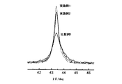
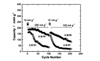
- Example 1 is an X-ray diffraction chart of positive electrode active materials of Example 1, Example 2 and Comparative Example 1. It is the expansion chart which overwrites each X-ray-diffraction chart of FIG. It is the result of the thermal analysis of the positive electrode material of Example 1 and Comparative Example 1. 15 is a graph showing the results of Evaluation Example 7; 15 is a graph showing the results of Evaluation Example 8;
- the numerical range “ab” described in the present specification includes the lower limit a and the upper limit b in that range. And a numerical range can be constituted by combining these arbitrarily including the upper limit and lower limit, and the numerical value listed in the example. Furthermore, numerical values arbitrarily selected from these numerical ranges can be used as new upper and lower numerical values.
- Me is a transition metal including V.
- A is an element other than Nb, Me and O.
- x, y, z, p satisfy 0 ⁇ x ⁇ 1, 0 ⁇ y ⁇ 0.5, 0.3 ⁇ z ⁇ 1, 0 ⁇ p ⁇ 0.2.
- a peak attributable to the space group Fm-3m is observed in X-ray diffraction measurement using CuK ⁇ rays, but in addition to the peaks attributable to the space group Fm-3m, Peaks assignable to group I-43 m or space group R-3 m may be observed. For example, in “Fm-3m”, “-3" represents 3 with an upper line.
- a range of 0 ⁇ x ⁇ 0.5 is preferable, a range of 0.05 ⁇ x ⁇ 0.4 is more preferable, and a range of 0.1 ⁇ x ⁇ 0.3 is more preferable.
- a range of 0.05 ⁇ y ⁇ 0.5 is preferable, a range of 0.1 ⁇ y ⁇ 0.4 is more preferable, a range of 0.15 ⁇ y ⁇ 0.35 is more preferable, and 0. The range of 2 ⁇ y ⁇ 0.35 is more preferable.
- transition metals other than V that can be included in Me in the composition formula (1) include Mn, Fe, Ni, Co, and Cu.
- the element ratio of V in Me is preferably 0.5 or more, more preferably 0.7 or more, and still more preferably 0.9 or more.
- z in the composition formula (1) the range of 0.3 ⁇ z ⁇ 0.9 is preferable, the range of 0.3 ⁇ z ⁇ 0.8 is more preferable, and the range of 0.4 ⁇ z ⁇ 0.8 Is more preferred.
- the larger the value of z the larger the capacity of the positive electrode active material of the present invention per unit mass.
- A is an element other than Nb, Me and O, preferably an element selected from Be, Mg, Ca, Sr, Ba, Ra, Sc, Y, Ti, Zr and Al.
- A may be single or plural.
- A is considered to have the effect of stabilizing the structure of the positive electrode active material inside the positive electrode active material.
- p in the composition formula (1) it is preferable to satisfy 0 ⁇ p ⁇ 0.15, and it is more preferable to satisfy 0 ⁇ p ⁇ 0.1. If p is too large, the capacity of the positive electrode active material per unit mass may be reduced.
- the high crystallinity reflects the state in which the metal elements are more regularly arranged. Therefore, in the positive electrode active material of the present invention, the metal elements are regularly arranged, and as a result, in the positive electrode active material of the present invention, it can be said that electron conduction paths are regularly formed, It can be said that the positive electrode active material of the present invention is excellent in conductivity. On the other hand, in the case of a positive electrode active material in which the half width of the diffraction peak exceeds 0.43 °, it can be said that relatively large amounts of crystal distortion and defects exist, so it can be said that the positive electrode active material is inferior in conductivity.
- 0.40 degrees or less are preferable and, as for the said half value width in the positive electrode active material of this invention, 0.38 degrees or less is more preferable.
- the lower limit of the above-mentioned half width can be 0.2 °, 0.25 °, 0.3 °, for example.
- the positive electrode active material of the present invention is in a powder state, and the average particle diameter thereof is preferably 50 nm or more and 2 ⁇ m or less, more preferably 60 nm or more and 1 ⁇ m or less, and still more preferably 100 nm or more and 500 nm or less. It is considered that if the positive electrode active material has a small average particle diameter, the reaction area will be large and rapid charge and discharge will be possible.
- the average particle diameter of the positive electrode active material of this invention is an arithmetic mean of the longest diameter of each particle
- the plurality may be twenty, thirty, fifty, for example. The same applies to the average particle size of the material represented by the composition formula (1) described below.
- the manufacturing method of the positive electrode active material represented by following composition formula (1) including the manufacturing method of the positive electrode active material of this invention is demonstrated.
- the method for producing a positive electrode active material represented by the following composition formula (1) of the present invention is a) A step of preparing a material represented by the following composition formula (1), which shows a peak attributable to the space group Fm-3 m in X-ray diffraction measurement using CuK ⁇ ray; b) grinding the material, c) b) heating the material after step in the range of 400 to 900 ° C., It is characterized by including. Li 1 + x Nb y Me z A p O 2 (1) Me is a transition metal including V. A is an element other than Nb, Me and O. x, y, z, p satisfy 0 ⁇ x ⁇ 1, 0 ⁇ y ⁇ 0.5, 0.3 ⁇ z ⁇ 1, 0 ⁇ p ⁇ 0.2.
- the process a) will be described.
- a general positive electrode active material such as LiNi 1/3 Co 1/3 Mn 1/3 O 2 It may be synthesized by applying a solid phase method or a coprecipitation method.
- the material represented by the composition formula (1) can be produced by mixing and calcining lithium source, niobium source, Me source and the like in a desired ratio.
- a hydroxide is precipitated to form a precipitate from an aqueous solution in which niobium salt, Me salt and the like are mixed in a desired ratio, and then the precipitate and a lithium source are mixed and calcined.
- the material represented by the composition formula (1) can be manufactured.
- the firing temperature in the solid phase method and coprecipitation method is preferably 900 to 1200 ° C., more preferably 900 to 1100 ° C., and still more preferably 900 to 1000 ° C.
- the firing is preferably performed in an inert gas atmosphere such as helium or argon.
- lithium sources include lithium oxide, lithium hydroxide, lithium carbonate, lithium hydrogen carbonate and lithium fluoride.
- niobium source or niobium salt include niobium oxide, niobium hydroxide, niobium sulfate, niobium nitrate, niobium chloride, niobium fluoride and lithium niobate.
- Me source or Me salt include Me oxide, Me hydroxide, Me sulfate, Me nitrate, Me chloride, Me fluoride.
- the material represented by the composition formula (1) is pulverized.
- a grinder used at b) process a pin mill, a hammer mill, a ball mill, a disc mill, a roller mill, a jaw crusher, and a jet mill can be illustrated.
- a ball mill it may be ground at a rotational speed of 100 to 500 rpm within a range of 1 to 60 hours, preferably about 2 to 10 hours.
- the material represented by the composition formula (1) is preferably ground to an average particle diameter in the range of 50 nm to 2 ⁇ m, and is ground to a range of 60 nm to 1 ⁇ m. Is more preferable, and it is further preferable to be ground to a range of 100 nm to 500 nm.
- the step c) is a step of heating the material after the step b) within a range of 400 to 900.degree.
- the crystallinity of the material represented by the composition formula (1) subjected to the step b) can be improved.
- positioning of the metal atom inside of the material represented by the composition formula (1) which passed through process b) may be able to be equalized by the heating in process c).
- Nb rich spots and Me rich spots are observed in microscopic observation at several nm to 10 nm level. May be It is suggested that the interface between the Nb-rich site and the Me-rich site may be responsible for the passage of lithium ions associated with charge and discharge.
- the particle size of the material represented by the composition formula (1) does not greatly fluctuate.
- the heating temperature in the step is preferably in the range of 450 to 850 ° C., more preferably in the range of 500 to 850 ° C., still more preferably in the range of 600 to 850 ° C., particularly preferably in the range of 700 to 850 ° C. Preferably, the temperature in the range of 750 to 850 ° C. is most preferable.
- the heating temperature in the step is too high, particles of the material represented by the composition formula (1) may be bound to each other, and the particle diameter may be increased. c) If the heating temperature in the step is too low, the crystallinity of the material represented by the composition formula (1) does not improve.
- the heating time in the step c) depends on the heating temperature, but is preferably 0.1 to 10 hours, more preferably 0.5 to 5 hours, and still more preferably 0.5 to 3 hours.
- the step c) is preferably performed under an inert gas atmosphere such as helium or argon.
- the step b) carbon particles may be present together with the material represented by the composition formula (1) and pulverized.
- the step c) is a step of heating the mixture of the material represented by the composition formula (1) and the carbon particles after the step b) in the range of 400 to 900 ° C.
- the substance is a positive electrode material containing a positive electrode active material and carbon.
- the positive electrode material containing the positive electrode active material of the present invention and carbon may be referred to as the positive electrode material of the present invention.
- Carbon particles play a role as a conductive aid.
- the carbon particles are stirred together with the positive electrode active material in step b) and heated together with the positive electrode active material in step c) to produce a positive electrode material having excellent conductivity in which the positive electrode active material and carbon are uniformly mixed. Ru.
- composite particles in which a positive electrode active material and carbon are integrated may also be observed.
- the positive electrode material of the present invention a material having a weight change of 10% or less when heated to 800 ° C. can be mentioned.
- the weight change is a weight change when heating is performed in an inert gas atmosphere such as helium or argon.
- the relatively small change in weight is considered to be due to the heating in the step c).
- the mass ratio of the positive electrode active material to carbon in the positive electrode material of the present invention is preferably 30: 1 to 3: 1, more preferably 20: 1 to 4: 1, and still more preferably 15: 1 to 5: 1. .
- Examples of the carbon particles used in the step b) include carbon black, graphite and vapor grown carbon fiber.
- Examples of the carbon black include acetylene black, ketjen black (registered trademark), furnace black, channel black and the like.
- the positive electrode for a lithium ion secondary battery comprising the positive electrode active material of the present invention or the positive electrode material of the present invention is referred to as “the positive electrode of the present invention” and lithium comprising the positive electrode active material of the present invention or the positive electrode material of the present invention
- the ion secondary battery is referred to as "the lithium ion secondary battery of the present invention”.
- the positive electrode of the present invention comprises a positive electrode active material of the present invention or a positive electrode active material layer containing the positive electrode material of the present invention, and a current collector.
- the positive electrode active material layer is formed on the current collector.
- the blending ratio of the positive electrode active material of the present invention in the positive electrode active material layer can be, for example, 30 to 100% by mass, 40 to 90% by mass, and 50 to 80% by mass.
- the current collector refers to a chemically inert electron conductor for keeping current flowing to the electrode during discharge or charge of the lithium ion secondary battery.
- the material of the current collector is not particularly limited as long as it is a metal that can withstand a voltage suitable for the active material to be used.
- the material of the current collector is at least one selected from silver, copper, gold, aluminum, tungsten, cobalt, zinc, nickel, iron, platinum, tin, indium, titanium, ruthenium, tantalum, chromium, molybdenum, and stainless steel Etc. can be exemplified.
- the current collector may be coated with a known protective layer. What processed the surface of a collector by a well-known method may be used as a collector.
- the potential of the positive electrode is set to 4 V or more based on lithium, it is preferable to use aluminum as a current collector for the positive electrode.
- an aluminum or an aluminum alloy as the positive electrode current collector.
- aluminum refers to pure aluminum, and aluminum having a purity of 99.0% or more is referred to as pure aluminum.
- An alloy obtained by adding various elements to pure aluminum is called an aluminum alloy.
- aluminum alloys include Al-Cu, Al-Mn, Al-Fe, Al-Si, Al-Mg, Al-Mg-Si, and Al-Zn-Mg.
- Al or aluminum alloy specifically, for example, A1000 series alloys (pure aluminum series) such as JIS A1085 and A1N30, A3000 series alloys such as JIS A3003 and A3004 (Al-Mn series), JIS A8079, A8021 etc. A 8000 series alloys (Al-Fe series).
- the current collector can take the form of a foil, a sheet, a film, a line, a rod, a mesh or the like. Therefore, as the current collector, for example, metal foils such as copper foil, nickel foil, aluminum foil, and stainless steel foil can be suitably used.
- the thickness is preferably in the range of 1 ⁇ m to 100 ⁇ m.
- the positive electrode active material layer may contain a known positive electrode active material in addition to the positive electrode active material of the present invention.
- the positive electrode active material layer preferably contains a binder and a conductive auxiliary.
- a conductive support agent may be blended separately from the carbon of the positive electrode material of the present invention.
- the lithium ion secondary battery of the present invention comprises the positive electrode of the present invention, a negative electrode, an electrolytic solution, and a separator.
- the negative electrode includes a current collector and a negative electrode active material layer formed on the current collector.
- the negative electrode active material layer contains a known negative electrode active material.
- the current collector of the negative electrode may be appropriately selected from those described for the positive electrode of the present invention.
- both the positive electrode active material and the negative electrode active material may be collectively referred to as "active material”
- both the positive electrode active material layer and the negative electrode active material layer may be collectively referred to as the "active material layer”. .
- fluorine-containing resins such as polyvinylidene fluoride, polytetrafluoroethylene and fluororubber, thermoplastic resins such as polypropylene and polyethylene, imide resins such as polyimide and polyamideimide, alkoxysilyl group-containing resin, carboxymethyl cellulose
- fluorine-containing resins such as polyvinylidene fluoride, polytetrafluoroethylene and fluororubber
- thermoplastic resins such as polypropylene and polyethylene
- imide resins such as polyimide and polyamideimide
- alkoxysilyl group-containing resin such as carboxymethyl cellulose
- carboxymethyl cellulose carboxymethyl cellulose
- active material: binder 1: 0.005 to 1: 0.5.
- a conductive aid is added to enhance the conductivity of the electrode. Therefore, the conductive additive may be optionally added when the conductivity of the electrode is insufficient, and may not be added when the conductivity of the electrode is sufficiently excellent.
- the conductive support agent may be any chemically active high electron conductor, and carbon black fine particles such as carbon black, graphite, vapor grown carbon fiber, and various metal particles are exemplified. Ru. Examples of the carbon black include acetylene black, ketjen black (registered trademark), furnace black, channel black and the like. These conductive assistants can be added to the active material layer singly or in combination of two or more.
- an active material layer on the surface of a current collector current collection can be performed using conventionally known methods such as roll coating, die coating, dip coating, doctor blade method, spray coating, and curtain coating.
- the active material may be applied to the surface of the body.
- the active material or the positive electrode material of the present invention, a binder, a solvent, and a conductive auxiliary agent as needed are mixed to form a slurry, and the slurry is applied to the surface of a current collector and then dried. It is good to do.
- the solvent include N-methyl-2-pyrrolidone, methanol, methyl isobutyl ketone and water. The dried one may be compressed to increase the electrode density.
- a mixture containing an active material or the positive electrode material of the present invention, a binder, and, if necessary, a conductive auxiliary agent is prepared, and the mixture is pressure-bonded to the current collector to obtain an active material on the surface of the current collector.
- a layer may be formed.
- the separator separates the positive electrode and the negative electrode, and allows lithium ions to pass while preventing a short circuit due to the contact of the both electrodes.
- a known one may be employed, and polytetrafluoroethylene, polypropylene, polyethylene, polyimide, polyamide, polyaramid (Aromatic polyamide), polyester, synthetic resin such as polyacrylonitrile, polysaccharide such as cellulose, amylose, fibroin Examples thereof include porous materials, non-woven fabrics, and woven fabrics using one or more kinds of natural polymers such as keratin, lignin and suberin, and electrically insulating materials such as ceramics.
- the separator may have a multilayer structure.
- the electrolytic solution contains a non-aqueous solvent and an electrolyte dissolved in the non-aqueous solvent.
- cyclic carbonate As the non-aqueous solvent, cyclic carbonate, cyclic ester, chain carbonate, chain ester, ethers and the like can be used.
- cyclic carbonates include ethylene carbonate, propylene carbonate, butylene carbonate, and vinylene carbonate.
- cyclic esters include gamma butyrolactone, 2-methyl-gamma butyrolactone, acetyl-gamma butyrolactone, and gamma valerolactone.
- chain carbonates include dimethyl carbonate, diethyl carbonate, dibutyl carbonate, dipropyl carbonate, and ethyl methyl carbonate.
- chain esters examples include propionic acid alkyl ester, malonic acid dialkyl ester, acetic acid alkyl ester and the like.
- ethers tetrahydrofuran, 2-methyltetrahydrofuran, 1,4-dioxane, 1,2-dimethoxyethane, 1,2-diethoxyethane, 1,2-dibutoxyethane can be exemplified.
- non-aqueous solvent a compound in which part or all of hydrogens in the chemical structure of the above specific solvent is substituted with fluorine may be adopted.
- Examples of the electrolyte include lithium salts such as LiClO 4 , LiAsF 6 , LiPF 6 , LiBF 4 , LiCF 3 SO 3 , and LiN (CF 3 SO 2 ) 2 .
- a lithium salt such as LiClO 4 , LiPF 6 , LiBF 4 , LiCF 3 SO 3 and the like in a nonaqueous solvent such as fluoroethylene carbonate, ethylene carbonate, dimethyl carbonate, ethyl methyl carbonate and diethyl carbonate
- a nonaqueous solvent such as fluoroethylene carbonate, ethylene carbonate, dimethyl carbonate, ethyl methyl carbonate and diethyl carbonate
- the positive electrode and the negative electrode sandwich a separator to form an electrode body.
- the electrode body may be any of a laminated type in which a positive electrode, a separator and a negative electrode are stacked, or a wound type in which a laminate of a positive electrode, a separator and a negative electrode is wound.
- the shape of the lithium ion secondary battery of the present invention is not particularly limited, and various shapes such as cylindrical, square, coin, and laminate types can be adopted.
- the lithium ion secondary battery of the present invention may be mounted on a vehicle.
- the vehicle may be a vehicle using electric energy from a lithium ion secondary battery for all or part of its power source, and may be, for example, an electric vehicle or a hybrid vehicle.
- a lithium ion secondary battery is mounted on a vehicle, a plurality of lithium ion secondary batteries may be connected in series to form a battery pack.
- various household appliances driven by a battery such as a personal computer and a mobile communication apparatus, as well as a vehicle, an office apparatus, an industrial apparatus and the like can be mentioned.
- the lithium ion secondary battery of the present invention can be used in wind power generation, solar power generation, hydroelectric power generation, storage devices and power smoothing devices for electric power systems, power sources for power and / or accessories of ships, etc., aircraft, Power supply source for power of spacecraft and / or accessories, auxiliary power supply for vehicles not using electricity as power source, power supply for mobile home robots, power supply for system backup, power supply for uninterruptible power supply, You may use for the electrical storage apparatus which stores temporarily the electric power required for charge in the charge station etc. for electric vehicles.
- the mixture was mixed by a ball mill at 300 rpm for 5 hours to obtain a mixture.
- the mixture was molded and heated at 950 ° C. for 12 hours under an argon gas atmosphere to produce a calcined product.
- the manufactured baked product was used as the material of Example 1.
- the theoretical composition of the material of Example 1 is Li 1.25 Nb 0.25 V 0.5 O 2 .
- Step 9 parts by mass of the material of Example 1 and 1 part by mass of acetylene black were charged into a ball mill.
- the mixing by a ball mill at 300 rpm was performed for 54 hours to obtain a powdered mixture in which the material of Example 1 was crushed.
- no significant change was observed in the physical properties of the mixture at the mixing time of 6 hours by the ball mill at 300 rpm and the mixture at the time of 54 hours.
- Step b) The positive electrode material of Example 1 including the positive electrode active material of Example 1 and carbon was manufactured by heating the powdery mixture obtained in Step b under an argon gas atmosphere at 800 ° C. for 1 hour. .
- Lithium ion secondary battery manufacturing process A positive electrode material of Example 1, acetylene black as an additional conductive additive, polyvinylidene fluoride as a binder, and an appropriate amount of solvent were mixed to prepare a slurry. An aluminum foil was prepared as a current collector, a slurry was applied thereto, and the slurry was dried to obtain the positive electrode of Example 1 in which a positive electrode active material layer was formed on the surface of the current collector.
- the mass ratio of the positive electrode active material of Example 1, the conductive aid containing carbon of the positive electrode material of Example 1, and the binder is 76.5: 13. It was 5:10.
- Lithium foil was prepared and used as a negative electrode.
- a polyolefin porous membrane was prepared as a separator.
- an electrolyte was prepared by dissolving LiPF 6 at a concentration of 1 mol / L in a solvent in which 3 parts by volume of ethylene carbonate and 7 parts by volume of dimethyl carbonate were mixed.
- the separator was sandwiched between the positive electrode and the negative electrode of Example 1 to form an electrode body.
- the electrode body was housed in a coin-type battery case, and an electrolytic solution was further injected to obtain a sealed coin-type battery. The resultant was used as a lithium ion secondary battery of Example 1.
- Example 2 The positive electrode active material, the positive electrode material, the positive electrode, and the lithium ion secondary battery of Example 2 were manufactured in the same manner as in Example 1 except that the heating temperature in the step c) was set to 500 ° C.
- Comparative example 1 The positive electrode active material, the positive electrode material, the positive electrode, and the lithium ion secondary battery of Comparative Example 1 were manufactured in the same manner as in Example 1 except that step c) was not performed.
- the positive electrode material of Comparative Example 1 corresponds to the mixture at the end of step b) in Example 1 and Example 2.
- Example 2 X-ray diffraction measurement
- the positive electrode active materials of Example 1, Example 2 and Comparative Example 1 were analyzed by a powder X-ray diffraction measurement apparatus using CuK ⁇ radiation.
- the obtained X-ray diffraction chart is shown in FIG. From the X-ray diffraction chart of any positive electrode active material, a peak attributable to the space group Fm-3m was observed. Further, FIG. 2 shows an enlarged chart in which each X-ray diffraction chart is superimposed. In FIG. 2, the highest peak is the peak of Example 1, the next highest peak is the peak of Example 2, and the lowest peak is the peak of Comparative Example 1.
- the lithium ion secondary batteries of Example 1 and Comparative Example 1 were set to a current of 10 mA / g at room temperature under conditions of mass of the positive electrode active material, charged until the voltage was 4.3 V, and the voltage was 1 . After several charge and discharge cycles of discharging to 2 V, the current value is set to 200 mA / g, charging is performed to a voltage of 4.3 V, and charging is performed to a voltage of 1.2 V. The discharge cycle was performed 100 times.
- the current value is made 100 mA / g, the voltage is charged to 4.3 V, and the voltage is discharged to 1.2 V Then, the charge and discharge cycle was performed 100 times.
- the graph of the discharge capacity in each charge and discharge cycle is shown in FIG. From FIG. 4, the discharge capacity of the lithium ion secondary battery of Example 1 is higher than the discharge capacity of the lithium ion secondary battery of Comparative Example 1 under any conditions of the current values of 200 mA / g and 100 mA / g. I understand that.
- the graph of the discharge capacity in each charge and discharge cycle is shown in FIG. From FIG. 5, it can be seen that the lithium ion secondary battery of Example 1 has a capacity suitably maintained.
Landscapes
- Chemical & Material Sciences (AREA)
- Chemical Kinetics & Catalysis (AREA)
- Electrochemistry (AREA)
- General Chemical & Material Sciences (AREA)
- Inorganic Chemistry (AREA)
- Engineering & Computer Science (AREA)
- Materials Engineering (AREA)
- Battery Electrode And Active Subsutance (AREA)
Abstract
電池特性に優れるリチウムイオン二次電池を提供するための新たな正極活物質を提供すること。 CuKα線を用いたX線回折測定において空間群Fm-3mに帰属可能なピークを示し、下記組成式(1)で表される正極活物質であって、 前記X線回折測定における回折角2θ=42°~45°の間に観察される回折ピークの半値幅が、0.43°以下であることを特徴とする正極活物質。 Li1+xNbyMezApO2 (1) MeはVを含む遷移金属である。AはNb、Me、O以外の元素である。x、y、z、pは、0<x<1、0<y<0.5、0.3≦z<1、0≦p≦0.2を満足する。
Description
本発明は、リチウムイオン二次電池の正極活物質に関するものである。
リチウムイオン二次電池は小型で大容量であるため、携帯電話やノート型パソコンなどの種々の機器の電池として用いられている。リチウムイオン二次電池は、主な構成要素として、正極、負極及び電解液を備える。正極は、集電体と、該集電体の表面に形成され、正極活物質を含有する正極活物質層とを有する。
リチウムイオン二次電池の正極活物質としては、種々の材料が用いられることが知られており、また、優れた正極活物質となり得る材料が探求されている。例えば、特許文献1にて、空間群Fm-3mに帰属可能なピークを示し、下記組成式(1)で表される材料が、リチウムイオン二次電池の正極活物質として使用可能なことが報告されている。
Li1+xNbyMezApO2 (1)
(MeはVを含む遷移金属、0<x<1、0<y<0.5、0.3≦z<1、AはNb、Me、O以外の元素、0≦p≦0.2)
Li1+xNbyMezApO2 (1)
(MeはVを含む遷移金属、0<x<1、0<y<0.5、0.3≦z<1、AはNb、Me、O以外の元素、0≦p≦0.2)
近年、産業界からは、電池特性に優れるリチウムイオン二次電池が求められており、それを実現するための、新たな正極活物質が求められている。
本発明は、かかる事情に鑑みて為されたものであり、電池特性に優れるリチウムイオン二次電池を提供するための新たな正極活物質を提供することを目的とする。
本発明者は、特許文献1に記載の材料についての研究を行った。まず、特許文献1に記載の材料を粉砕して、粉末状とした。粉末状の材料を正極活物質として具備するリチウムイオン二次電池を製造し、評価したところ、改良の余地があることに気が付いた。そして、本発明者の鋭意検討の結果、粉砕して粉末状とした材料を、特定の条件下で加熱したところ、加熱後の材料には結晶構造の格子パターンや粒子径に大きな変化が観察されなかったものの、加熱後の材料を正極活物質として具備するリチウムイオン二次電池を製造し、評価したところ、その電池特性が改善したことを知見した。
本発明者のかかる知見に基づく、加熱後の材料の更なる詳細な分析の結果、本発明は完成された。
本発明者のかかる知見に基づく、加熱後の材料の更なる詳細な分析の結果、本発明は完成された。
本発明の正極活物質は、
CuKα線を用いたX線回折測定において空間群Fm-3mに帰属可能なピークを示し、下記組成式(1)で表される正極活物質であって、
前記X線回折測定における回折角2θ=42°~45°の間に観察される回折ピークの半値幅が、0.43°以下であることを特徴とする。
Li1+xNbyMezApO2 (1)
MeはVを含む遷移金属である。AはNb、Me、O以外の元素である。x、y、z、pは、0<x<1、0<y<0.5、0.3≦z<1、0≦p≦0.2を満足する。
CuKα線を用いたX線回折測定において空間群Fm-3mに帰属可能なピークを示し、下記組成式(1)で表される正極活物質であって、
前記X線回折測定における回折角2θ=42°~45°の間に観察される回折ピークの半値幅が、0.43°以下であることを特徴とする。
Li1+xNbyMezApO2 (1)
MeはVを含む遷移金属である。AはNb、Me、O以外の元素である。x、y、z、pは、0<x<1、0<y<0.5、0.3≦z<1、0≦p≦0.2を満足する。
本発明の下記組成式(1)で表される正極活物質の製造方法は、
a)CuKα線を用いたX線回折測定において空間群Fm-3mに帰属可能なピークを示し、下記組成式(1)で表される材料を準備する工程、
b)前記材料を粉砕する工程、
c)b)工程後の材料を400~900℃の範囲内で加熱する工程、
を含むことを特徴とする。
Li1+xNbyMezApO2 (1)
MeはVを含む遷移金属である。AはNb、Me、O以外の元素である。x、y、z、pは、0<x<1、0<y<0.5、0.3≦z<1、0≦p≦0.2を満足する。
a)CuKα線を用いたX線回折測定において空間群Fm-3mに帰属可能なピークを示し、下記組成式(1)で表される材料を準備する工程、
b)前記材料を粉砕する工程、
c)b)工程後の材料を400~900℃の範囲内で加熱する工程、
を含むことを特徴とする。
Li1+xNbyMezApO2 (1)
MeはVを含む遷移金属である。AはNb、Me、O以外の元素である。x、y、z、pは、0<x<1、0<y<0.5、0.3≦z<1、0≦p≦0.2を満足する。
本発明の正極活物質に因り、電池特性に優れるリチウムイオン二次電池を提供できる。
以下に、本発明を実施するための形態を説明する。なお、特に断らない限り、本明細書に記載された数値範囲「a~b」は、下限a及び上限bをその範囲に含む。そして、これらの上限値及び下限値、ならびに実施例中に列記した数値も含めてそれらを任意に組み合わせることで数値範囲を構成し得る。さらに、これらの数値範囲内から任意に選択した数値を、新たな上限や下限の数値とすることができる。
本発明の正極活物質は、
CuKα線を用いたX線回折測定において空間群Fm-3mに帰属可能なピークを示し、下記組成式(1)で表される正極活物質であって、
前記X線回折測定における回折角2θ=42°~45°の間に観察される回折ピークの半値幅が、0.43°以下であることを特徴とする。
Li1+xNbyMezApO2 (1)
MeはVを含む遷移金属である。AはNb、Me、O以外の元素である。x、y、z、pは、0<x<1、0<y<0.5、0.3≦z<1、0≦p≦0.2を満足する。
CuKα線を用いたX線回折測定において空間群Fm-3mに帰属可能なピークを示し、下記組成式(1)で表される正極活物質であって、
前記X線回折測定における回折角2θ=42°~45°の間に観察される回折ピークの半値幅が、0.43°以下であることを特徴とする。
Li1+xNbyMezApO2 (1)
MeはVを含む遷移金属である。AはNb、Me、O以外の元素である。x、y、z、pは、0<x<1、0<y<0.5、0.3≦z<1、0≦p≦0.2を満足する。
本発明の正極活物質においては、CuKα線を用いたX線回折測定において空間群Fm-3mに帰属可能なピークが観察されるが、空間群Fm-3mに帰属可能なピーク以外にも、空間群I-43mや空間群R-3mに帰属可能なピークが観察されてもよい。なお、例えば「Fm-3m」において、「-3」は上線を付した3を表したものである。
組成式(1)におけるxとしては、0<x<0.5の範囲が好ましく、0.05≦x≦0.4の範囲がより好ましく、0.1≦x≦0.3の範囲がさらに好ましい。yとしては、0.05≦y<0.5の範囲が好ましく、0.1≦y≦0.4の範囲がより好ましく、0.15≦y≦0.35の範囲がさらに好ましく、0.2≦y≦0.35の範囲がさらに好ましい。
組成式(1)におけるMeに含まれ得るV以外の遷移金属としては、Mn、Fe、Ni、Co、Cuを例示できる。MeにおけるVの元素比は、0.5以上が好ましく、0.7以上がより好ましく、0.9以上がさらに好ましい。組成式(1)におけるzとしては、0.3≦z≦0.9の範囲が好ましく、0.3≦z≦0.8の範囲がより好ましく、0.4≦z≦0.8の範囲がさらに好ましい。zの値が大きいほど、単位質量あたりの本発明の正極活物質の容量は大きい。
AはNb、Me、O以外の元素であり、好ましくは、Be、Mg、Ca、Sr、Ba、Ra、Sc、Y、Ti、Zr、Alから選択される元素である。Aは、単独でもよいし、複数でもよい。Aは正極活物質内部で、正極活物質の構造を安定化する効果を奏すると考えられる。組成式(1)におけるpとしては、0≦p≦0.15を満足するのが好ましく、0≦p≦0.1を満足するのがより好ましい。pが過大であれば、単位質量あたりの正極活物質の容量が小さくなる場合がある。
本発明の正極活物質は、X線回折測定における回折角2θ=42°~45°の間に観察される回折ピークの半値幅が0.43°以下である。X線回折測定における回折角2θ=42°~45°の間に観察される回折ピークは、空間群Fm-3mで表される結晶構造の(104)面に由来するピークである。ここで、回折ピークの半値幅が小さいとは、当該回折ピークのピーク形状がシャープであり結晶性が高いことを意味する。したがって、本発明の正極活物質の結晶性が比較的高いといえる。また、結晶性が高いとは、金属元素がより規則的に配列している状態が反映されているといえる。したがって、本発明の正極活物質においては、金属元素が規則的に配列しており、その結果、本発明の正極活物質においては、電子の導電パスが規則的に形成されているといえるし、本発明の正極活物質は導電性に優れるといえる。他方、上記回折ピークの半値幅が0.43°を超える正極活物質においては、結晶の歪みや欠損が比較的多く存在するといえるため、その正極活物質は導電性に劣るといえる。
本発明の正極活物質における上記半値幅は、0.40°以下が好ましく、0.38°以下がより好ましい。上記半値幅の下限を敢えて述べると、0.2°、0.25°、0.3°を例示できる。
本発明の正極活物質は粉末状態であり、その平均粒子径としては、50nm以上2μm以下が好ましく、60nm以上1μm以下がより好ましく、100nm以上500nm以下がさらに好ましい。平均粒子径が小さい正極活物質であれば反応面積が大きくなり、速やかな充放電が可能になると考えられる。なお、本発明の正極活物質の平均粒子径は、本発明の正極活物質の複数個の粒子を電子顕微鏡で観察した際の、各粒子の最長径の算術平均である。複数個とは、20個、30個、50個を例示できる。以下に述べる組成式(1)で表される材料の平均粒子径についても同様である。
本発明の正極活物質の製造方法を包含する、下記組成式(1)で表される正極活物質の製造方法について説明する。
本発明の下記組成式(1)で表される正極活物質の製造方法は、
a)CuKα線を用いたX線回折測定において空間群Fm-3mに帰属可能なピークを示し、下記組成式(1)で表される材料を準備する工程、
b)前記材料を粉砕する工程、
c)b)工程後の材料を400~900℃の範囲内で加熱する工程、
を含むことを特徴とする。
Li1+xNbyMezApO2 (1)
MeはVを含む遷移金属である。AはNb、Me、O以外の元素である。x、y、z、pは、0<x<1、0<y<0.5、0.3≦z<1、0≦p≦0.2を満足する。
本発明の下記組成式(1)で表される正極活物質の製造方法は、
a)CuKα線を用いたX線回折測定において空間群Fm-3mに帰属可能なピークを示し、下記組成式(1)で表される材料を準備する工程、
b)前記材料を粉砕する工程、
c)b)工程後の材料を400~900℃の範囲内で加熱する工程、
を含むことを特徴とする。
Li1+xNbyMezApO2 (1)
MeはVを含む遷移金属である。AはNb、Me、O以外の元素である。x、y、z、pは、0<x<1、0<y<0.5、0.3≦z<1、0≦p≦0.2を満足する。
まず、a)工程について説明する。
a)工程における組成式(1)で表される材料を準備するには、LiNi1/3Co1/3Mn1/3O2などの一般的な正極活物質を製造する際に採用される、固相法や共沈法を応用して合成すればよい。固相法の場合には、リチウム源、ニオブ源、Me源などを所望の比率で混合し、焼成することで、組成式(1)で表される材料を製造できる。共沈法の場合には、ニオブ塩、Me塩などを所望の比率で混合した水溶液から、水酸化物を沈殿させて沈殿物とし、次いで、沈殿物とリチウム源とを混合して焼成することで、組成式(1)で表される材料を製造できる。固相法及び共沈法の焼成温度としては、900~1200℃が好ましく、900~1100℃がより好ましく、900~1000℃がさらに好ましい。焼成は、ヘリウムやアルゴンなどの不活性ガス雰囲気下で行うのが好ましい。
a)工程における組成式(1)で表される材料を準備するには、LiNi1/3Co1/3Mn1/3O2などの一般的な正極活物質を製造する際に採用される、固相法や共沈法を応用して合成すればよい。固相法の場合には、リチウム源、ニオブ源、Me源などを所望の比率で混合し、焼成することで、組成式(1)で表される材料を製造できる。共沈法の場合には、ニオブ塩、Me塩などを所望の比率で混合した水溶液から、水酸化物を沈殿させて沈殿物とし、次いで、沈殿物とリチウム源とを混合して焼成することで、組成式(1)で表される材料を製造できる。固相法及び共沈法の焼成温度としては、900~1200℃が好ましく、900~1100℃がより好ましく、900~1000℃がさらに好ましい。焼成は、ヘリウムやアルゴンなどの不活性ガス雰囲気下で行うのが好ましい。
リチウム源としては、酸化リチウム、水酸化リチウム、炭酸リチウム、炭酸水素リチウム、フッ化リチウムを例示できる。ニオブ源又はニオブ塩としては、酸化ニオブ、水酸化ニオブ、硫酸ニオブ、硝酸ニオブ、塩化ニオブ、フッ化ニオブ、ニオブ酸リチウムを例示できる。Me源又はMe塩としては、酸化Me、水酸化Me、硫酸Me、硝酸Me、塩化Me、フッ化Meを例示できる。
b)工程において、組成式(1)で表される材料は粉砕される。b)工程で用いられる粉砕機としては、ピンミル、ハンマーミル、ボールミル、ディスクミル、ローラーミル、ジョークラッシャー、ジェットミルを例示できる。例えば、ボールミルを用いた場合には、回転速度100~500rpmで1~60時間の範囲内、好ましくは2~10時間程度、粉砕すればよい。
b)工程において、組成式(1)で表される材料は、その平均粒子径が50nm以上2μm以下の範囲となるまで粉砕されるのが好ましく、60nm以上1μm以下の範囲となるまで粉砕されるのがより好ましく、100nm以上500nm以下の範囲となるまで粉砕されるのがさらに好ましい。
c)工程は、b)工程後の材料を400~900℃の範囲内で加熱する工程である。c)工程での加熱により、b)工程を経た組成式(1)で表される材料の結晶性を向上できる。また、c)工程での加熱により、b)工程を経た組成式(1)で表される材料内部の金属原子の配置を、均一化できる場合がある。なお、c)工程での加熱により、金属原子の配置を均一化できた場合であっても、数nm~10nm水準での微視的な観察においては、Nbリッチ箇所とMeリッチ箇所が観察される場合がある。かかるNbリッチ箇所とMeリッチ箇所との界面は、充放電に伴うリチウムイオンの通路を担う可能性が示唆される。
c)工程においては、組成式(1)で表される材料の粒子径は大きく変動しない。
c)工程の加熱温度としては、450~850℃の範囲内が好ましく、500~850℃の範囲内がより好ましく、600~850℃の範囲内がさらに好ましく、700~850℃の範囲内が特に好ましく、750~850℃の範囲内が最も好ましい。c)工程の加熱温度が高すぎると、組成式(1)で表される材料の粒子同士が結着して、その粒子径が大きくなる場合がある。c)工程の加熱温度が低すぎると、組成式(1)で表される材料の結晶性が向上しない。
c)工程の加熱温度としては、450~850℃の範囲内が好ましく、500~850℃の範囲内がより好ましく、600~850℃の範囲内がさらに好ましく、700~850℃の範囲内が特に好ましく、750~850℃の範囲内が最も好ましい。c)工程の加熱温度が高すぎると、組成式(1)で表される材料の粒子同士が結着して、その粒子径が大きくなる場合がある。c)工程の加熱温度が低すぎると、組成式(1)で表される材料の結晶性が向上しない。
c)工程の加熱時間は加熱温度にもよるが、0.1~10時間が好ましく、0.5~5時間がより好ましく、0.5~3時間がさらに好ましい。c)工程は、ヘリウムやアルゴンなどの不活性ガス雰囲気下で行われるのが好ましい。
また、b)工程において、組成式(1)で表される材料と共に炭素粒子を存在させて、粉砕してもよい。この場合、c)工程は、b)工程後の組成式(1)で表される材料及び炭素粒子の混合物を400~900℃の範囲内で加熱する工程となり、そして、c)工程で製造される物は、正極活物質と炭素を含む正極材料となる。以下、本発明の正極活物質と炭素を含む正極材料を、本発明の正極材料ということがある。
炭素粒子は導電助剤としての役割を担っている。炭素粒子がb)工程にて正極活物質と共に撹拌され、かつc)工程にて正極活物質と共に加熱されることで、正極活物質と炭素が均一に混合した導電性に優れる正極材料が製造される。b)工程及びc)工程を経ることにより製造される正極材料においては、正極活物質と炭素が一体化している複合粒子も観察される場合がある。
また、本発明の正極材料の一態様としては、800℃まで加熱した際の重量変化が10%以下のものを挙げることができる。なお、ここでの重量変化は、ヘリウムやアルゴンなどの不活性ガス雰囲気下で加熱した場合の重量変化である。本発明の正極材料の一態様において、重量変化が比較的少ないのは、c)工程において加熱を経験しているためと考えられる。
本発明の正極材料における、正極活物質と炭素との質量比としては、30:1~3:1が好ましく、20:1~4:1がより好ましく、15:1~5:1がさらに好ましい。
b)工程で用いられる炭素粒子としては、カーボンブラック、黒鉛及び気相法炭素繊維(Vapor Grown Carbon Fiber)が例示される。カーボンブラックとしては、アセチレンブラック、ケッチェンブラック(登録商標)、ファーネスブラック、チャンネルブラックなどが例示される。
以下、本発明の正極活物質又は本発明の正極材料を具備するリチウムイオン二次電池用正極を「本発明の正極」といい、本発明の正極活物質又は本発明の正極材料を具備するリチウムイオン二次電池を「本発明のリチウムイオン二次電池」という。
本発明の正極は、本発明の正極活物質又は本発明の正極材料を含む正極活物質層、及び、集電体を具備する。正極活物質層は集電体上に形成される。正極活物質層における本発明の正極活物質の配合割合として、30~100質量%、40~90質量%、50~80質量%を例示できる。
集電体は、リチウムイオン二次電池の放電又は充電の間、電極に電流を流し続けるための化学的に不活性な電子伝導体をいう。集電体の材料は、使用する活物質に適した電圧に耐え得る金属であれば特に制限はない。集電体の材料としては、銀、銅、金、アルミニウム、タングステン、コバルト、亜鉛、ニッケル、鉄、白金、錫、インジウム、チタン、ルテニウム、タンタル、クロム、モリブデンから選ばれる少なくとも一種、並びにステンレス鋼などの金属材料を例示することができる。集電体は公知の保護層で被覆されていても良い。集電体の表面を公知の方法で処理したものを集電体として用いても良い。
正極の電位をリチウム基準で4V以上とする場合には、正極用集電体としてアルミニウムを採用するのが好ましい。
具体的には、正極用集電体として、アルミニウム又はアルミニウム合金からなるものを用いるのが好ましい。ここでアルミニウムは、純アルミニウムを指し、純度99.0%以上のアルミニウムを純アルミニウムと称する。純アルミニウムに種々の元素を添加して合金としたものをアルミニウム合金と称する。アルミニウム合金としては、Al-Cu系、Al-Mn系、Al-Fe系、Al-Si系、Al-Mg系、Al-Mg-Si系、Al-Zn-Mg系が挙げられる。
また、アルミニウム又はアルミニウム合金として、具体的には、例えばJIS A1085、A1N30等のA1000系合金(純アルミニウム系)、JIS A3003、A3004等のA3000系合金(Al-Mn系)、JIS A8079、A8021等のA8000系合金(Al-Fe系)が挙げられる。
集電体は箔、シート、フィルム、線状、棒状、メッシュなどの形態をとることができる。そのため、集電体として、例えば、銅箔、ニッケル箔、アルミニウム箔、ステンレス箔などの金属箔を好適に用いることができる。集電体が箔、シート、フィルム形態の場合は、その厚みが1μm~100μmの範囲内であることが好ましい。
正極活物質層には、本発明の正極活物質以外に公知の正極活物質が含まれていてもよい。また、正極活物質層には、結着剤及び導電助剤が含まれているのが好ましい。既に導電助剤としての炭素を具備する本発明の正極材料を含む正極活物質層に対しても、本発明の正極材料の炭素とは別に、導電助剤が配合されてもよい。正極活物質層に含まれる結着剤及び導電助剤としては、後述の負極で説明するものを適宜適切に採用すればよい。
本発明のリチウムイオン二次電池は、具体的に、本発明の正極と、負極と、電解液と、セパレータとを具備する。負極は、集電体と集電体上に形成された負極活物質層を具備する。負極活物質層には、公知の負極活物質が含まれる。負極の集電体としては、本発明の正極で説明したものから適宜適切に選択すればよい。以下、正極活物質及び負極活物質の両者を総合して「活物質」という場合があり、また、正極活物質層及び負極活物質層の両者を総合して「活物質層」という場合がある。
結着剤としては、ポリフッ化ビニリデン、ポリテトラフルオロエチレン、フッ素ゴム等の含フッ素樹脂、ポリプロピレン、ポリエチレン等の熱可塑性樹脂、ポリイミド、ポリアミドイミド等のイミド系樹脂、アルコキシシリル基含有樹脂、カルボキシメチルセルロース、スチレンブタジエンゴムなどの公知のものを採用すればよい。
活物質層中の結着剤の配合割合は、質量比で、活物質:結着剤=1:0.005~1:0.5であるのが好ましい。結着剤が少なすぎると電極の成形性が低下し、また、結着剤が多すぎると電極のエネルギー密度が低くなるためである。
導電助剤は、電極の導電性を高めるために添加される。そのため、導電助剤は、電極の導電性が不足する場合に任意に加えればよく、電極の導電性が十分に優れている場合には加えなくても良い。導電助剤としては化学的に不活性な電子高伝導体であれば良く、炭素質微粒子であるカーボンブラック、黒鉛、気相法炭素繊維(Vapor Grown Carbon Fiber)、および各種金属粒子などが例示される。カーボンブラックとしては、アセチレンブラック、ケッチェンブラック(登録商標)、ファーネスブラック、チャンネルブラックなどが例示される。これらの導電助剤を単独又は二種以上組み合わせて活物質層に添加することができる。活物質層中の導電助剤の配合割合は、質量比で、活物質:導電助剤=1:0.01~1:0.7であるのが好ましい。導電助剤が少なすぎると効率のよい導電パスを形成できず、また、導電助剤が多すぎると活物質層の成形性が悪くなるとともに電極のエネルギー密度が低くなるためである。
集電体の表面に活物質層を形成させるには、ロールコート法、ダイコート法、ディップコート法、ドクターブレード法、スプレーコート法、カーテンコート法などの従来から公知の方法を用いて、集電体の表面に活物質を塗布すればよい。具体的には、活物質若しくは本発明の正極材料、結着剤、溶剤、及び必要に応じて導電助剤を混合してスラリーにしてから、当該スラリーを集電体の表面に塗布後、乾燥するとよい。溶剤としては、N-メチル-2-ピロリドン、メタノール、メチルイソブチルケトン、水を例示できる。電極密度を高めるべく、乾燥後のものを圧縮しても良い。また、活物質若しくは本発明の正極材料、結着剤、及び必要に応じて導電助剤を含む混合物を調製し、当該混合物を集電体に圧着させることで、集電体の表面に活物質層を形成させてもよい。
セパレータは、正極と負極とを隔離し、両極の接触による短絡を防止しつつ、リチウムイオンを通過させるものである。セパレータとしては、公知のものを採用すればよく、ポリテトラフルオロエチレン、ポリプロピレン、ポリエチレン、ポリイミド、ポリアミド、ポリアラミド(Aromatic polyamide)、ポリエステル、ポリアクリロニトリル等の合成樹脂、セルロース、アミロース等の多糖類、フィブロイン、ケラチン、リグニン、スベリン等の天然高分子、セラミックスなどの電気絶縁性材料を1種若しくは複数用いた多孔体、不織布、織布などを挙げることができる。また、セパレータは多層構造としてもよい。
電解液は、非水溶媒と非水溶媒に溶解した電解質とを含んでいる。
非水溶媒としては、環状カーボネート、環状エステル、鎖状カーボネート、鎖状エステル、エーテル類等が使用できる。環状カーボネートとしては、エチレンカーボネート、プロピレンカーボネート、ブチレンカーボネート、ビニレンカーボネートを例示でき、環状エステルとしては、ガンマブチロラクトン、2-メチル-ガンマブチロラクトン、アセチル-ガンマブチロラクトン、ガンマバレロラクトンを例示できる。鎖状カーボネートとしては、ジメチルカーボネート、ジエチルカーボネート、ジブチルカーボネート、ジプロピルカーボネート、エチルメチルカーボネートを例示でき、鎖状エステルとしては、プロピオン酸アルキルエステル、マロン酸ジアルキルエステル、酢酸アルキルエステル等を例示できる。エーテル類としては、テトラヒドロフラン、2-メチルテトラヒドロフラン、1,4-ジオキサン、1,2-ジメトキシエタン、1,2-ジエトキシエタン、1,2-ジブトキシエタンを例示できる。非水溶媒としては、上記具体的な溶媒の化学構造のうち一部又は全部の水素がフッ素に置換した化合物を採用しても良い。
電解質としては、LiClO4、LiAsF6、LiPF6、LiBF4、LiCF3SO3、LiN(CF3SO2)2等のリチウム塩を例示できる。
電解液としては、フルオロエチレンカーボネート、エチレンカーボネート、ジメチルカーボネート、エチルメチルカーボネート、ジエチルカーボネートなどの非水溶媒に、LiClO4、LiPF6、LiBF4、LiCF3SO3などのリチウム塩を0.5mol/Lから1.7mol/L程度の濃度で溶解させた溶液を例示できる。
本発明のリチウムイオン二次電池の具体的な製造方法について述べる。
例えば、正極と負極とでセパレータを挟持して電極体とする。電極体は、正極、セパレータ及び負極を重ねた積層型、又は、正極、セパレータ及び負極の積層体を捲いた捲回型のいずれの型にしても良い。正極の集電体および負極の集電体から外部に通ずる正極端子および負極端子までを、集電用リード等を用いて接続した後に、電極体に電解液を加えてリチウムイオン二次電池とするとよい。
例えば、正極と負極とでセパレータを挟持して電極体とする。電極体は、正極、セパレータ及び負極を重ねた積層型、又は、正極、セパレータ及び負極の積層体を捲いた捲回型のいずれの型にしても良い。正極の集電体および負極の集電体から外部に通ずる正極端子および負極端子までを、集電用リード等を用いて接続した後に、電極体に電解液を加えてリチウムイオン二次電池とするとよい。
本発明のリチウムイオン二次電池の形状は特に限定されるものでなく、円筒型、角型、コイン型、ラミネート型等、種々の形状を採用することができる。
本発明のリチウムイオン二次電池は、車両に搭載してもよい。車両は、その動力源の全部あるいは一部にリチウムイオン二次電池による電気エネルギーを使用している車両であればよく、例えば、電気車両、ハイブリッド車両などであるとよい。車両にリチウムイオン二次電池を搭載する場合には、リチウムイオン二次電池を複数直列に接続して組電池とするとよい。リチウムイオン二次電池を搭載する機器としては、車両以外にも、パーソナルコンピュータ、携帯通信機器など、電池で駆動される各種の家電製品、オフィス機器、産業機器などが挙げられる。さらに、本発明のリチウムイオン二次電池は、風力発電、太陽光発電、水力発電その他電力系統の蓄電装置及び電力平滑化装置、船舶等の動力及び/又は補機類の電力供給源、航空機、宇宙船等の動力及び/又は補機類の電力供給源、電気を動力源に用いない車両の補助用電源、移動式の家庭用ロボットの電源、システムバックアップ用電源、無停電電源装置の電源、電動車両用充電ステーションなどにおいて充電に必要な電力を一時蓄える蓄電装置に用いてもよい。
以上、本発明の実施形態を説明したが、本発明は、上記実施形態に限定されるものではない。本発明の要旨を逸脱しない範囲において、当業者が行い得る変更、改良等を施した種々の形態にて実施することができる。
以下に、各種の具体例を示し、本発明をより具体的に説明する。なお、本発明は、これらの具体例によって限定されるものではない。
(実施例1)
a)工程
Li2CO3、Nb2O5及びV2O3を、Li:Nb:Vが1.25:0.25:0.5となる比率で秤量し、これらの粉末をボールミルに投入した。300rpmでのボールミルによる混合を5時間行い、混合物を得た。混合物を成形した上で、アルゴンガス雰囲気下、950℃で12時間加熱して、焼成物を製造した。製造された焼成物を実施例1の材料とした。実施例1の材料の理論上の組成は、Li1.25Nb0.25V0.5O2である。
a)工程
Li2CO3、Nb2O5及びV2O3を、Li:Nb:Vが1.25:0.25:0.5となる比率で秤量し、これらの粉末をボールミルに投入した。300rpmでのボールミルによる混合を5時間行い、混合物を得た。混合物を成形した上で、アルゴンガス雰囲気下、950℃で12時間加熱して、焼成物を製造した。製造された焼成物を実施例1の材料とした。実施例1の材料の理論上の組成は、Li1.25Nb0.25V0.5O2である。
b)工程
9質量部の実施例1の材料と1質量部のアセチレンブラックをボールミルに投入した。300rpmでのボールミルによる混合を54時間行い、実施例1の材料が粉砕された粉末状の混合物を得た。なお、300rpmでのボールミルによる混合時間が6時間の時点の混合物と54時間の時点の混合物とは、両者の物性に大きな変化が観察されなかった。
9質量部の実施例1の材料と1質量部のアセチレンブラックをボールミルに投入した。300rpmでのボールミルによる混合を54時間行い、実施例1の材料が粉砕された粉末状の混合物を得た。なお、300rpmでのボールミルによる混合時間が6時間の時点の混合物と54時間の時点の混合物とは、両者の物性に大きな変化が観察されなかった。
c)工程
b)工程で得た粉末状の混合物を、アルゴンガス雰囲気下、800℃で1時間加熱することで、実施例1の正極活物質及び炭素を含む実施例1の正極材料を製造した。
b)工程で得た粉末状の混合物を、アルゴンガス雰囲気下、800℃で1時間加熱することで、実施例1の正極活物質及び炭素を含む実施例1の正極材料を製造した。
リチウムイオン二次電池製造工程
実施例1の正極材料、追加の導電助剤としてアセチレンブラック、結着剤としてポリフッ化ビニリデン、及び、適量の溶剤を混合して、スラリーとした。集電体としてアルミニウム箔を準備し、これにスラリーを塗布して、乾燥することで、集電体表面に正極活物質層が形成された実施例1の正極を得た。
実施例1の正極の正極活物質層における、実施例1の正極活物質、実施例1の正極材料の炭素を包含する導電助剤、及び結着剤の質量比は、76.5:13.5:10であった。
実施例1の正極材料、追加の導電助剤としてアセチレンブラック、結着剤としてポリフッ化ビニリデン、及び、適量の溶剤を混合して、スラリーとした。集電体としてアルミニウム箔を準備し、これにスラリーを塗布して、乾燥することで、集電体表面に正極活物質層が形成された実施例1の正極を得た。
実施例1の正極の正極活物質層における、実施例1の正極活物質、実施例1の正極材料の炭素を包含する導電助剤、及び結着剤の質量比は、76.5:13.5:10であった。
リチウム箔を準備し、これを負極とした。セパレータとしてポリオレフィン製多孔質膜を準備した。また、エチレンカーボネート3体積部及びジメチルカーボネート7体積部を混合した溶媒にLiPF6を1mol/Lの濃度で溶解した電解液を準備した。セパレータを実施例1の正極と負極とで挟持し電極体とした。この電極体をコイン型電池ケースに収容し、さらに電解液を注入して、密閉型のコイン型電池を得た。これを実施例1のリチウムイオン二次電池とした。
(実施例2)
c)工程における加熱温度を500℃とした以外は、実施例1と同様の方法で、実施例2の正極活物質、正極材料、正極及びリチウムイオン二次電池を製造した。
c)工程における加熱温度を500℃とした以外は、実施例1と同様の方法で、実施例2の正極活物質、正極材料、正極及びリチウムイオン二次電池を製造した。
(比較例1)
c)工程を行わなかった以外は、実施例1と同様の方法で、比較例1の正極活物質、正極材料、正極及びリチウムイオン二次電池を製造した。比較例1の正極材料は、実施例1及び実施例2におけるb)工程終了時の混合物に該当する。
c)工程を行わなかった以外は、実施例1と同様の方法で、比較例1の正極活物質、正極材料、正極及びリチウムイオン二次電池を製造した。比較例1の正極材料は、実施例1及び実施例2におけるb)工程終了時の混合物に該当する。
(評価例1:SEM観察)
走査型電子顕微鏡(SEM)にて、実施例1、実施例2及び比較例1の正極材料の観察を行った。
その結果、c)工程の有無やc)工程の加熱温度の違いに因る正極活物質の大きさについて、大きな変化は観察されなかった。c)工程での加熱では、正極活物質の粒子径には大きな変化がないといえる。
また、実施例1のSEM像に観察された正極活物質の粒子50個につき、それぞれ粒子の最長となる長さを最長径として測定し、その算術平均値を算出した。その結果、実施例1の正極活物質の平均粒子径は、0.34μmと算出された。
走査型電子顕微鏡(SEM)にて、実施例1、実施例2及び比較例1の正極材料の観察を行った。
その結果、c)工程の有無やc)工程の加熱温度の違いに因る正極活物質の大きさについて、大きな変化は観察されなかった。c)工程での加熱では、正極活物質の粒子径には大きな変化がないといえる。
また、実施例1のSEM像に観察された正極活物質の粒子50個につき、それぞれ粒子の最長となる長さを最長径として測定し、その算術平均値を算出した。その結果、実施例1の正極活物質の平均粒子径は、0.34μmと算出された。
(評価例2:X線回折測定)
CuKα線を用いた粉末X線回折測定装置にて、実施例1、実施例2及び比較例1の正極活物質の分析を行った。得られたX線回折チャートを図1に示す。いずれの正極活物質のX線回折チャートからも、空間群Fm-3mに帰属可能なピークが観察された。
また、図2に各X線回折チャートを重ね書きした拡大チャートを示す。図2において、最も高いピークが実施例1のピークであり、次に高いピークが実施例2のピークであり、最も低いピークが比較例1のピークである。各X線回折チャートにおける回折角2θ=42°~45°の間に観察される回折ピークの半値幅は、実施例1は0.365°であり、実施例2は0.425°であり、比較例1は0.643°であった。
c)工程により、上記半値幅の値が小さくなることがわかる。
CuKα線を用いた粉末X線回折測定装置にて、実施例1、実施例2及び比較例1の正極活物質の分析を行った。得られたX線回折チャートを図1に示す。いずれの正極活物質のX線回折チャートからも、空間群Fm-3mに帰属可能なピークが観察された。
また、図2に各X線回折チャートを重ね書きした拡大チャートを示す。図2において、最も高いピークが実施例1のピークであり、次に高いピークが実施例2のピークであり、最も低いピークが比較例1のピークである。各X線回折チャートにおける回折角2θ=42°~45°の間に観察される回折ピークの半値幅は、実施例1は0.365°であり、実施例2は0.425°であり、比較例1は0.643°であった。
c)工程により、上記半値幅の値が小さくなることがわかる。
(評価例3:TEM-EDX)
透過型電子顕微鏡(TEM)とエネルギー分散型X線分析装置(EDX)を組み合わせたTEM-EDXにて、実施例1及び比較例1の正極活物質の分析を行った。
その結果、比較例1の正極活物質においては、NbとVとがまだらな状態であること(偏析した状態であること)が確認されたものの、実施例1の正極活物質においてはNbとVとが比較的均一な状態であること(偏析した状態が解消されたこと)が確認された。c)工程により、金属原子の配置が均一化されたといえる。
なお、実施例1の正極活物質におけるNbとVとが比較的均一な状態においても、微視的には比較的Nb濃度が高いNbリッチ箇所と、比較的V濃度が高いVリッチ箇所が観察された。
透過型電子顕微鏡(TEM)とエネルギー分散型X線分析装置(EDX)を組み合わせたTEM-EDXにて、実施例1及び比較例1の正極活物質の分析を行った。
その結果、比較例1の正極活物質においては、NbとVとがまだらな状態であること(偏析した状態であること)が確認されたものの、実施例1の正極活物質においてはNbとVとが比較的均一な状態であること(偏析した状態が解消されたこと)が確認された。c)工程により、金属原子の配置が均一化されたといえる。
なお、実施例1の正極活物質におけるNbとVとが比較的均一な状態においても、微視的には比較的Nb濃度が高いNbリッチ箇所と、比較的V濃度が高いVリッチ箇所が観察された。
(評価例4:TEM観察)
TEMにて、実施例1及び比較例1の正極材料の分析を行った。
その結果、比較例1の正極材料においては、正極活物質と炭素粒子が部分的に結着している様子が観察された。それに対して、実施例1の正極材料においては、正極活物質の表面全体を炭素が厚さ5nm程度で被覆している粒子も確認された。c)工程により、炭素粒子の炭素が正極活物質の表面を被覆して、炭素被覆正極活物質が形成されたといえる。
TEMにて、実施例1及び比較例1の正極材料の分析を行った。
その結果、比較例1の正極材料においては、正極活物質と炭素粒子が部分的に結着している様子が観察された。それに対して、実施例1の正極材料においては、正極活物質の表面全体を炭素が厚さ5nm程度で被覆している粒子も確認された。c)工程により、炭素粒子の炭素が正極活物質の表面を被覆して、炭素被覆正極活物質が形成されたといえる。
(評価例5:Tg測定)
熱重量測定装置を用いて、以下の条件で、実施例1及び比較例1の正極材料の熱分析を行った。結果を図3に示す。
雰囲気:アルゴン
昇温速度:5℃/min.
温度範囲:室温から800℃
容器:アルミナ製
熱重量測定装置を用いて、以下の条件で、実施例1及び比較例1の正極材料の熱分析を行った。結果を図3に示す。
雰囲気:アルゴン
昇温速度:5℃/min.
温度範囲:室温から800℃
容器:アルミナ製
図3から、比較例1の正極材料における重量減少は15%以上であるが、実施例1の正極材料における重量減少は8%程度であることが判明した。
(評価例6:インピーダンス)
実施例1及び比較例1のリチウムイオン二次電池につき、周波数10mHz~100kHzの条件でのインピーダンス測定を行った。その結果、比較例1のリチウムイオン二次電池と比較して、実施例1のリチウムイオン二次電池においては、1Hz~1kHzの範囲での著しいインピーダンスの低下が観察された。例えば、12Hzにおいて、比較例1のリチウムイオン二次電池の抵抗は176オームであったが、実施例1のリチウムイオン二次電池の抵抗は71オームであった。
実施例1及び比較例1のリチウムイオン二次電池につき、周波数10mHz~100kHzの条件でのインピーダンス測定を行った。その結果、比較例1のリチウムイオン二次電池と比較して、実施例1のリチウムイオン二次電池においては、1Hz~1kHzの範囲での著しいインピーダンスの低下が観察された。例えば、12Hzにおいて、比較例1のリチウムイオン二次電池の抵抗は176オームであったが、実施例1のリチウムイオン二次電池の抵抗は71オームであった。
(評価例7:レート特性)
実施例1及び比較例1のリチウムイオン二次電池につき、室温条件下、正極活物質の質量に対する電流値を10mA/gに設定して、電圧が4.3Vとなるまで充電し、電圧が1.2Vとなるまで放電するとの充放電サイクルを数回行った後に、電流値を200mA/gにして、電圧が4.3Vとなるまで充電し、電圧が1.2Vとなるまで放電するとの充放電サイクルを100回行った。次いで、再び電流値を10mA/gにして充放電サイクルを数回行った後に、電流値を100mA/gにして、電圧が4.3Vとなるまで充電し、電圧が1.2Vとなるまで放電するとの充放電サイクルを100回行った。
実施例1及び比較例1のリチウムイオン二次電池につき、室温条件下、正極活物質の質量に対する電流値を10mA/gに設定して、電圧が4.3Vとなるまで充電し、電圧が1.2Vとなるまで放電するとの充放電サイクルを数回行った後に、電流値を200mA/gにして、電圧が4.3Vとなるまで充電し、電圧が1.2Vとなるまで放電するとの充放電サイクルを100回行った。次いで、再び電流値を10mA/gにして充放電サイクルを数回行った後に、電流値を100mA/gにして、電圧が4.3Vとなるまで充電し、電圧が1.2Vとなるまで放電するとの充放電サイクルを100回行った。
各充放電サイクルにおける放電容量のグラフを図4に示す。図4から、電流値が200mA/g及び100mA/gのいずれの条件においても、実施例1のリチウムイオン二次電池の放電容量が、比較例1のリチウムイオン二次電池の放電容量よりも高いことがわかる。
(評価例8:サイクル特性)
実施例1及び比較例1のリチウムイオン二次電池につき、室温条件下、正極活物質の質量に対する電流値を10mA/gに設定して、電圧が4.8Vとなるまで充電し、電圧が1.5Vとなるまで放電するとの充放電サイクルを25回行った。
実施例1及び比較例1のリチウムイオン二次電池につき、室温条件下、正極活物質の質量に対する電流値を10mA/gに設定して、電圧が4.8Vとなるまで充電し、電圧が1.5Vとなるまで放電するとの充放電サイクルを25回行った。
各充放電サイクルにおける放電容量のグラフを図5に示す。図5から、実施例1のリチウムイオン二次電池は、容量が好適に維持されていることがわかる。
Claims (10)
- a)CuKα線を用いたX線回折測定において空間群Fm-3mに帰属可能なピークを示し、下記組成式(1)で表される材料を準備する工程、
b)前記材料を粉砕する工程、
c)b)工程後の材料を400~900℃の範囲内で加熱する工程、
を含むことを特徴とする下記組成式(1)で表される正極活物質の製造方法。
Li1+xNbyMezApO2 (1)
MeはVを含む遷移金属である。AはNb、Me、O以外の元素である。x、y、z、pは、0<x<1、0<y<0.5、0.3≦z<1、0≦p≦0.2を満足する。 - 前記b)工程が、前記材料を粉砕して、その平均粒子径を50nm以上2μm以下とする工程である請求項1に記載の正極活物質の製造方法。
- a)CuKα線を用いたX線回折測定において空間群Fm-3mに帰属可能なピークを示し、下記組成式(1)で表される材料を準備する工程、
b)前記材料及び炭素粒子の混合物を粉砕する工程、
c)b)工程後の混合物を400~900℃の範囲内で加熱する工程、
を含むことを特徴とする正極材料の製造方法。
Li1+xNbyMezApO2 (1)
MeはVを含む遷移金属である。AはNb、Me、O以外の元素である。x、y、z、pは、0<x<1、0<y<0.5、0.3≦z<1、0≦p≦0.2を満足する。 - CuKα線を用いたX線回折測定において空間群Fm-3mに帰属可能なピークを示し、下記組成式(1)で表される正極活物質であって、
前記X線回折測定における回折角2θ=42°~45°の間に観察される回折ピークの半値幅が、0.43°以下であることを特徴とする正極活物質。
Li1+xNbyMezApO2 (1)
MeはVを含む遷移金属である。AはNb、Me、O以外の元素である。x、y、z、pは、0<x<1、0<y<0.5、0.3≦z<1、0≦p≦0.2を満足する。 - 平均粒子径が50nm以上2μm以下である請求項4に記載の正極活物質。
- 請求項4又は5に記載の正極活物質と炭素とを含む正極材料。
- 正極活物質と炭素が一体化している請求項6に記載の正極材料。
- 800℃まで加熱した際の重量変化が10%以下である請求項6又は7に記載の正極材料。
- 請求項4若しくは5に記載の正極活物質又は請求項6~8のいずれか1項に記載の正極材料を具備する正極。
- 請求項9に記載の正極を具備するリチウムイオン二次電池。
Applications Claiming Priority (2)
| Application Number | Priority Date | Filing Date | Title |
|---|---|---|---|
| JP2017-123758 | 2017-06-23 | ||
| JP2017123758A JP2019008990A (ja) | 2017-06-23 | 2017-06-23 | 正極活物質 |
Publications (1)
| Publication Number | Publication Date |
|---|---|
| WO2018235758A1 true WO2018235758A1 (ja) | 2018-12-27 |
Family
ID=64735626
Family Applications (1)
| Application Number | Title | Priority Date | Filing Date |
|---|---|---|---|
| PCT/JP2018/023054 Ceased WO2018235758A1 (ja) | 2017-06-23 | 2018-06-18 | 正極活物質 |
Country Status (2)
| Country | Link |
|---|---|
| JP (1) | JP2019008990A (ja) |
| WO (1) | WO2018235758A1 (ja) |
Cited By (1)
| Publication number | Priority date | Publication date | Assignee | Title |
|---|---|---|---|---|
| CN114503329A (zh) * | 2019-10-17 | 2022-05-13 | 松下知识产权经营株式会社 | 固体电解质材料及使用了它的电池 |
Citations (3)
| Publication number | Priority date | Publication date | Assignee | Title |
|---|---|---|---|---|
| JP2012503293A (ja) * | 2008-09-23 | 2012-02-02 | コリア ベーシック サイエンス インスティテュート | リチウム二次電池用負極活物質、その製造方法およびそれを含むリチウム二次電池 |
| JP2016103456A (ja) * | 2014-11-17 | 2016-06-02 | 株式会社Gsユアサ | 非水電解質蓄電素子用活物質 |
| JP2017027881A (ja) * | 2015-07-27 | 2017-02-02 | 株式会社Gsユアサ | 非水電解質電池用正極活物質 |
-
2017
- 2017-06-23 JP JP2017123758A patent/JP2019008990A/ja active Pending
-
2018
- 2018-06-18 WO PCT/JP2018/023054 patent/WO2018235758A1/ja not_active Ceased
Patent Citations (3)
| Publication number | Priority date | Publication date | Assignee | Title |
|---|---|---|---|---|
| JP2012503293A (ja) * | 2008-09-23 | 2012-02-02 | コリア ベーシック サイエンス インスティテュート | リチウム二次電池用負極活物質、その製造方法およびそれを含むリチウム二次電池 |
| JP2016103456A (ja) * | 2014-11-17 | 2016-06-02 | 株式会社Gsユアサ | 非水電解質蓄電素子用活物質 |
| JP2017027881A (ja) * | 2015-07-27 | 2017-02-02 | 株式会社Gsユアサ | 非水電解質電池用正極活物質 |
Cited By (2)
| Publication number | Priority date | Publication date | Assignee | Title |
|---|---|---|---|---|
| CN114503329A (zh) * | 2019-10-17 | 2022-05-13 | 松下知识产权经营株式会社 | 固体电解质材料及使用了它的电池 |
| CN114503329B (zh) * | 2019-10-17 | 2024-12-13 | 松下知识产权经营株式会社 | 固体电解质材料及使用了它的电池 |
Also Published As
| Publication number | Publication date |
|---|---|
| JP2019008990A (ja) | 2019-01-17 |
Similar Documents
| Publication | Publication Date | Title |
|---|---|---|
| JP5704986B2 (ja) | 非水電解質二次電池用正極材料及び非水電解質二次電池 | |
| JP7446595B2 (ja) | リチウム金属複合酸化物粉末の製造方法 | |
| JP2015213038A (ja) | 非水電解質二次電池用正極材料および非水電解質二次電池 | |
| KR20100105387A (ko) | 비수전해액 2차 전지 | |
| JP6803028B2 (ja) | リチウム金属複合酸化物粉末の製造方法及びリチウム金属複合酸化物粉末 | |
| JP2008311209A (ja) | 非水電解質二次電池 | |
| CN101510604B (zh) | 复合负极活性材料及其制备方法以及含其的负极和锂电池 | |
| JP7087889B2 (ja) | 複合粒子 | |
| WO2016042728A1 (ja) | MSix(Mは第3~9族元素から選択される少なくとも一元素。ただし、1/3≦x≦3)含有シリコン材料およびその製造方法 | |
| CN104854035A (zh) | 复合金属氧化物、复合金属氧化物的制造方法和钠二次电池 | |
| JP2017050204A (ja) | 非水電解質二次電池用正極材料、その製造方法および非水電解質二次電池 | |
| JP6962154B2 (ja) | リチウムイオン二次電池 | |
| WO2009116841A1 (ko) | 리튬 이차 전지용 양극 활물질 및 이를 포함하는 리튬 이차 전지 | |
| JP7131258B2 (ja) | 複合粒子の製造方法 | |
| JP2021086667A (ja) | TiSi2及びSi含有負極活物質 | |
| JP2019192373A (ja) | 正極活物質 | |
| JP6443675B2 (ja) | スピネル型結晶構造のLiaMxMnyO4粉末を含む正極及びリチウムイオン二次電池、並びにこれらの製造方法 | |
| JP2019102308A (ja) | 正極活物質 | |
| JP6939045B2 (ja) | 電気デバイス | |
| WO2018190048A1 (ja) | 正極活物質 | |
| JP2020053308A (ja) | 複合粒子 | |
| JP6252864B2 (ja) | シリコン材料の製造方法 | |
| JP2019091580A (ja) | 正極活物質 | |
| JP2019008990A (ja) | 正極活物質 | |
| WO2017073063A1 (ja) | シリコン材料の製造方法 |
Legal Events
| Date | Code | Title | Description |
|---|---|---|---|
| 121 | Ep: the epo has been informed by wipo that ep was designated in this application |
Ref document number: 18820496 Country of ref document: EP Kind code of ref document: A1 |
|
| NENP | Non-entry into the national phase |
Ref country code: DE |
|
| 122 | Ep: pct application non-entry in european phase |
Ref document number: 18820496 Country of ref document: EP Kind code of ref document: A1 |