WO2018235589A1 - 車両搭載機器のハウジング - Google Patents
車両搭載機器のハウジング Download PDFInfo
- Publication number
- WO2018235589A1 WO2018235589A1 PCT/JP2018/021513 JP2018021513W WO2018235589A1 WO 2018235589 A1 WO2018235589 A1 WO 2018235589A1 JP 2018021513 W JP2018021513 W JP 2018021513W WO 2018235589 A1 WO2018235589 A1 WO 2018235589A1
- Authority
- WO
- WIPO (PCT)
- Prior art keywords
- housing
- sealing agent
- holding portion
- agent holding
- housing member
- Prior art date
- Legal status (The legal status is an assumption and is not a legal conclusion. Google has not performed a legal analysis and makes no representation as to the accuracy of the status listed.)
- Ceased
Links
Images




Classifications
-
- F—MECHANICAL ENGINEERING; LIGHTING; HEATING; WEAPONS; BLASTING
- F16—ENGINEERING ELEMENTS AND UNITS; GENERAL MEASURES FOR PRODUCING AND MAINTAINING EFFECTIVE FUNCTIONING OF MACHINES OR INSTALLATIONS; THERMAL INSULATION IN GENERAL
- F16J—PISTONS; CYLINDERS; SEALINGS
- F16J15/00—Sealings
- F16J15/02—Sealings between relatively-stationary surfaces
- F16J15/14—Sealings between relatively-stationary surfaces by means of granular or plastic material, or fluid
-
- F—MECHANICAL ENGINEERING; LIGHTING; HEATING; WEAPONS; BLASTING
- F16—ENGINEERING ELEMENTS AND UNITS; GENERAL MEASURES FOR PRODUCING AND MAINTAINING EFFECTIVE FUNCTIONING OF MACHINES OR INSTALLATIONS; THERMAL INSULATION IN GENERAL
- F16H—GEARING
- F16H57/00—General details of gearing
- F16H57/02—Gearboxes; Mounting gearing therein
- F16H57/029—Gearboxes; Mounting gearing therein characterised by means for sealing the gearboxes, e.g. to improve airtightness
-
- B—PERFORMING OPERATIONS; TRANSPORTING
- B62—LAND VEHICLES FOR TRAVELLING OTHERWISE THAN ON RAILS
- B62D—MOTOR VEHICLES; TRAILERS
- B62D1/00—Steering controls, i.e. means for initiating a change of direction of the vehicle
- B62D1/02—Steering controls, i.e. means for initiating a change of direction of the vehicle vehicle-mounted
- B62D1/16—Steering columns
-
- B—PERFORMING OPERATIONS; TRANSPORTING
- B62—LAND VEHICLES FOR TRAVELLING OTHERWISE THAN ON RAILS
- B62D—MOTOR VEHICLES; TRAILERS
- B62D5/00—Power-assisted or power-driven steering
- B62D5/04—Power-assisted or power-driven steering electrical, e.g. using an electric servo-motor connected to, or forming part of, the steering gear
- B62D5/0403—Power-assisted or power-driven steering electrical, e.g. using an electric servo-motor connected to, or forming part of, the steering gear characterised by constructional features, e.g. common housing for motor and gear box
Definitions
- the present invention relates to a housing of a vehicle-mounted device.
- Patent Document 1 discloses a housing of a vehicle-mounted device in which a first member and a second member are joined with a liquid gasket at a joining surface.
- One of the objects of the present invention is to provide a housing of a vehicle-mounted device capable of improving the sealing property of the joint surface.
- a housing for a vehicle-mounted device is a liquid sealant provided in a first sealing agent holding portion, a second sealing agent holding portion, a first sealing agent holding portion and a second sealing agent holding portion And.
- the first sealing agent holding portion is a recessed groove opened in one of the first bonding surface or the second bonding surface.
- the first sealing agent holding portion is disposed at an intermediate portion in the thickness direction of the first housing member.
- the second sealing agent holding portion is a concave portion opened to the first bonding surface, and is disposed closer to the first inner side than the first sealing agent holding portion in the thickness direction of the first housing member, and the first bonding surface And a concave portion for holding the sealing agent between the second bonding surface and the second bonding surface.
- the sealability of a joint surface can be improved.
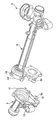
- FIG. 1 is a front view of a power steering device 1 according to a first embodiment.
- FIG. 2 is an exploded perspective view of a gear housing 4 of the first embodiment.
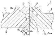
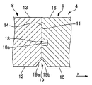
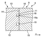
- FIG. 2 is an axial sectional view of a gear housing 4; It is a principal part enlarged view of FIG. It is the figure which looked at the 1st housing member 8 from the X-axis positive direction side.
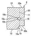
- FIG. 7 is an enlarged view of a main part of the first housing member 8 immediately before the first bonding surface 11 is machined. It is a principal part enlarged view of FIG. 3 which shows other embodiment. It is a principal part enlarged view of FIG. 3 which shows other embodiment. It is a principal part enlarged view of FIG. 3 which shows other embodiment. It is a principal part enlarged view of FIG. 3 which shows other embodiment.
- FIG. 1 is a front view of the power steering device 1 of the first embodiment.
- the power steering device 1 is a vehicle mounted device mounted on a vehicle having an engine as a power source.
- the power steering apparatus 1 includes a steering mechanism 2, an electric motor 3, a gear housing (housing) 4 and a motor housing 5.
- the steering mechanism 2 converts the rotational movement of the steering wheel (not shown) into a linear movement of the pair of tie rods 6, 6.
- a front wheel (not shown) is connected to the pair of tie rods 6, 6.
- the electric motor 3 applies a steering force to the steering mechanism 2.
- the electric motor 3 is, for example, a three-phase brushless motor.
- the output of the electric motor 3 is controlled by a motor control unit (not shown) in accordance with the steering torque of the driver input to the steering wheel and the vehicle speed.
- the gear housing 4 is disposed such that its axial direction is along the vehicle width direction.
- the gear housing 4 is formed by casting using an aluminum alloy.
- the gear housing 4 accommodates a part of the steering mechanism 2 and a rack bar and a ball screw mechanism (not shown) inside.
- the ball screw mechanism converts the rotational force of the electric motor 3 into the propulsive force of the rack bar.
- the motor housing 5 is formed by casting using an aluminum alloy.
- the motor housing 5 accommodates the electric motor 3 therein.
- the motor housing 5 is fixed to the gear housing 4.
- One axial end of the dust boot 7 is fixed to both axial ends of the gear housing 4.
- the dust boot 7 is formed in a bellows shape using a synthetic resin or the like.
- the other axial end of the dust boot 7 is fixed to the tie rod 6.
- FIG. 2 is an exploded perspective view of the gear housing 4 of the first embodiment
- FIG. 3 is an axial sectional view of the gear housing 4.
- the gear housing 4 has a two-divided structure in which the first housing member 8 and the second housing member 9 are joined in a state of abutting in the axial direction of the gear housing 4.
- the X axis is set in the axial direction of the gear housing 4, and the direction from the first housing member 8 toward the second housing member 9 is defined as the X axis positive direction.
- a direction around the X axis is taken as a circumferential direction
- a direction orthogonal to the X axis and going from the inside to the outside of the gear housing 4 is taken as a thickness direction.
- an internal space for accommodating a part of the rack bar and the ball screw mechanism is formed inside the abutting position of the first housing member 8 and the second housing member 9.
- the first housing member 8 and the second housing member 9 are fastened together by five bolts and nuts (coupling members) 10.
- the first housing member 8 has five first bolt insertion holes (first coupling member insertion holes) 8 a penetrating in the X-axis direction on the outer side in the thickness direction of the abutting position with the second housing member 9.
- the respective first bolt insertion holes 8a are disposed apart from one another in the circumferential direction.
- the second housing member 9 has five second bolt insertion holes (second coupling member insertion holes) 9 a penetrating in the X-axis direction on the outer side in the thickness direction of the butting position with the first housing member 8.
- the respective second bolt insertion holes 9a are spaced apart from each other at positions corresponding to the respective first bolt insertion holes 8a in the circumferential direction.
- the bolts of the bolt and nut 10 pass through the first bolt insertion hole 8a and the second bolt insertion hole 9a.
- the first housing member 8 has a first joint surface 11, a first inner side surface 12 and a first outer side surface 13.
- the first bonding surface 11 extends in the thickness direction.
- the first bonding surface 11 is formed by machining, and the surface roughness is set such that the arithmetic average roughness Ra is 6.4 [ ⁇ m] or less.
- the first inner side surface 12 extends in the negative X-axis direction from the negative X-axis direction end of an inclined surface 19a described later formed at the inner end in the thickness direction of the first bonding surface 11.
- the first outer side surface 13 extends from the outer end in the thickness direction of the first bonding surface 11 in the negative X-axis direction.
- the second housing member 9 has a second joint surface 14, a second inner side surface 15 and a second outer side surface 16.
- the second bonding surface 14 extends in the thickness direction. In the state where the second joint surface 14 is in contact with the first joint surface 11, the first housing member 8 and the second housing member 9 are coupled.
- the second bonding surface 14 is formed by machining, and the surface roughness thereof is set to an arithmetic average roughness Ra of 6.4 [ ⁇ m] or less.
- a liquid sealant 17 which is a liquid gasket is applied between the first joint surface 11 and the second joint surface 14.
- the second inner side surface 15 extends from the inner end in the thickness direction of the second bonding surface 14 in the positive X-axis direction. The position of the second inner side surface 15 in the thickness direction coincides with the first inner side surface 12.
- the second outer side surface 16 extends from the outer end in the thickness direction of the second bonding surface 14 in the positive X-axis direction. The position of the second outer side surface 16 in the thickness direction coincides with the first outer side surface 13.
- the gear housing 4 aims to improve the sealability of the joint surfaces of the first housing member 8 and the second housing member 9.
- a sealing agent holding unit 19 is provided.
- the first sealing agent holding portion 18 is a recessed groove formed in the first bonding surface 11.
- the first sealing agent holding portion 18 is disposed at an intermediate portion in the thickness direction of the first housing member 8. More specifically, the first sealing agent holding portion 18 is disposed on the inner side than the central portion B of the region A excluding the second sealing agent holding portion 19 in the thickness direction.
- the middle part includes not only the middle part of the bisection but also any position except the inner end and the outer end.
- the first sealant holding portion 18 has a bottom surface 18a and a pair of side wall surfaces 18b and 18b.
- the bottom surface 18 a has a concave arc shape facing the second bonding surface 14 and opening toward the X-axis positive direction side (the second bonding surface 14 side).
- the pair of side wall surfaces 18 b and 18 b are provided on both sides of the bottom surface 18 a in the thickness direction and face each other.
- the pair of side wall surfaces 18 b and 18 b extend in the X-axis direction and connect the bottom surface 18 a and the first joint surface 11.
- the fifth is a view of the first housing member 8 as viewed from the X-axis positive direction side, and the first sealing agent holding portion 18 is annularly connected as viewed from the X-axis direction and is closer to each first bolt insertion hole 8a. It is disposed on the inner side in the thickness direction.
- the same applies to the second sealing agent holding portion 19, and the inclined surface 19 a is annularly connected when viewed from the X-axis direction, and is disposed on the inner side in the thickness direction than the first sealing agent holding portion 18.
- the second sealing agent holding portion 19 is a recess provided at the inner end in the thickness direction of the first bonding surface 11.
- the second sealing agent holding portion 19 is formed between the inclined surface 19 a formed on the first bonding surface 11 and the second bonding surface 14.
- the inclined surface 19 a is formed at the inner end in the thickness direction of the first bonding surface 11.
- the inclined surface 19 a inclines in the negative X-axis direction from the outside in the thickness direction toward the inside.
- the inferior angle ⁇ is set to 30 degrees or more and less than 45 degrees.
- FIG. 6 is an enlarged view of an essential part of the first housing member 8 immediately before the first joint surface 11 is machined.
- the unmachined first housing member 8 formed by casting has a dimension adjusting portion 20.
- the dimension adjustment unit 20 is provided on the X-axis positive direction side with respect to the second sealing agent holding unit 19 in the X-axis direction.
- the thickness direction position of the outer side surface 20a coincides with the first outer side surface 13.
- the thickness direction position of the inner side surface 20b coincides with the end of the second sealing agent holding unit 19 in the positive X-axis direction.
- a bent portion 21 is formed between the second sealing agent holding portion 19 and the dimension adjustment portion 20.
- the X-axis negative direction end of the dimension adjustment unit 20 is cut in the thickness direction by machining, and the machined surface becomes the first joint surface 11.
- the first sealing agent holding portion 18 (the bottom surface 18a and the pair of side wall surfaces 18b and 18b) and the second sealing agent holding portion 19 (the inclined surface 19a) are not machined, so the casting surface (black Surface).
- the gear housing 4 of the first embodiment has the first sealing agent holding portion 18 and the first sealing agent holding portion 18 in the thickness direction of the first housing member 8 and the second housing member 9 in the joint surface between the first housing member 8 and the second housing member 9.
- a second sealing agent holding portion 19 is provided.
- the liquid sealant cured inside the first sealing agent holding portion 18 and the second sealing agent holding portion 19 functions as a double sealing portion with respect to the bonding surface.
- the second sealing agent holding portion 19 is provided at the end on the same side as the first inner side surface 12 in the thickness direction of the first housing member 8.
- the second sealing agent holding portion 19 is exposed on the inner side surface of the gear housing 4, since the second sealing agent holding portion 19 is on the inner side of the gear housing 4, the operator mistakenly mistaken the liquid sealant 17 of the second sealing agent holding portion 19. It is unlikely to touch the Therefore, the risk of a drop in sealability due to the absence of the liquid sealant 17 can be reduced.
- the second sealing agent holding portion 19 has the second sealing agent holding portion 19 in the direction (X-axis direction) in which the dimension of the first housing member 8 in the thickness direction of the first housing member 8 is orthogonal to the first bonding surface 11. It has an inclined surface 19a which gradually decreases from the end on the opposite side (X-axis negative direction side) to the second housing member 9 toward the end on the same side (X-axis positive direction side) as the second housing member 9 .
- X-axis negative direction side the second housing member 9 toward the end on the same side (X-axis positive direction side) as the second housing member 9 .
- the second sealing agent holding portion 19 of Embodiment 1 since the second sealing agent holding portion 19 of Embodiment 1 has no corner, the filling property of the liquid sealant 17 in the second sealing agent holding portion 19 can be improved.
- the first housing member 8 has the dimension adjusting portion 20, and the dimension adjusting portion 20 is provided on the same side as the second housing member 9 with respect to the second sealing agent holding portion 19 in the direction orthogonal to the first joint surface 11.
- the position of the end on the same side as the first inner surface 12 in the thickness direction of the first housing member 8 is the same as the end on the same side as the second housing member 9 of the second sealing agent holding portion 19.
- the first joint surface 11 is provided at an end on the same side as the first housing member 8 in the direction orthogonal to the first joint surface 11, and the first joint surface 11 is machined by machining. It has a face.
- the cast product has low dimensional accuracy and does not have high surface accuracy (flatness) as a joint surface. Therefore, by providing the dimension adjusting unit 20 and cutting the dimension adjusting unit 20 by machining, the necessary dimensional accuracy and the surface accuracy as the bonding surface can be obtained, and the dimensional accuracy of the first housing member 8 can be improved.
- the cutting amount in size adjustment is different for each product, when the cutting amount is large, when the second sealing agent holding portion 19 is cut, the space for filling the liquid sealant 17 runs short, and as a result, There is a possibility that the amount of filling may run short. Therefore, by providing the dimension adjustment unit 20 separately from the second sealing agent holding unit 19, it is possible to suppress the insufficient filling amount of the liquid sealant 17 in the second sealing agent holding unit 19.
- the first housing member 8 has a bending portion 21 between the second sealing agent holding portion 19 and the dimension adjusting portion 20 in the direction orthogonal to the first bonding surface 11. Since the boundary between the second sealing agent holding portion 19 and the size adjusting portion 20 is clarified by the bent portion 21, whether or not the size adjusting portion 20 remains after machining, that is, the second sealing agent holding It becomes easy to check whether or not the part 19 has been cut.
- the first sealing agent holding portion 18 is provided closer to the first inner side surface 12 than the central portion B in the area A excluding the second sealing agent holding portion 19 in the thickness direction of the first housing member 8.
- the second sealant 17 filled in the periphery of the first sealing agent holding portion 18 is The amount of protrusion to the side of the outer surface 13 can be suppressed. As described above, the liquid sealant 17 does not cause any problem as much as it overflows to the first inner side 12 side.
- the second sealing agent holding portion 19 has an inferior angle ⁇ of 30 degrees or more and less than 45 degrees among angles with the direction orthogonal to the first bonding surface 11.
- ⁇ is narrower than 30 degrees
- the internal space of the second sealing agent holding portion 19 is narrow, and the fillability of the liquid sealant 17 is degraded.
- ⁇ is 45 degrees or more
- the distance between the inclined surface 19a and the second bonding surface 14 is too large, and the adhesion of the liquid sealant 17 may be deteriorated. Therefore, by setting ⁇ to be not less than 30 degrees and less than 45 degrees, it is possible to achieve both the filling property and the adhesiveness of the liquid sealant 17.
- the first housing member 8 and the second housing member 9 are castings formed by casting, and the first sealing agent holding portion 18 and the second sealing agent holding portion 19 have a cast surface on at least a part of the surface. Have.
- the casting surface has irregularities, and the surface area is larger than that of a flat shape. Therefore, the adhesion of the liquid sealant 17 in the first sealing agent holding portion 18 and the second sealing agent holding portion 19 can be improved.
- the first outer surface 13 has an end on the same side as the second outer surface 16 in the direction orthogonal to the first bonding surface 11 adjacent to an end on the same side as the first outer surface 13 of the second outer surface 16. It has a shape. That is, the first outer side surface 13 and the second outer side surface 16 are adjacent to each other, and no recess is formed in the joint portion at the outer end in the thickness direction of the gear housing 4. Thereby, the amount of the liquid sealant 17 adhering to this portion can be reduced. As a result, it is possible to reduce the complexity when the operator erroneously contacts the liquid sealant 17 attached to the outside of the gear housing 4.
- intricacy refers to contamination of the outer surface of the gear housing 4 by the liquid sealant 17, contamination of workers' clothing, etc., for example.
- water and the like do not easily accumulate in the joint portion at the outer end in the thickness direction of the gear housing 4, the infiltration of water and the like into the inside of the gear housing 4 can be suppressed.
- the first sealing agent holding portion 18 is provided on both sides of the bottom surface 18 a facing the second bonding surface 14 in the direction orthogonal to the first bonding surface 11 and the bottom surface 18 a in the thickness direction of the first housing member 8
- the bottom surface 18a has a concave arc shape opening toward the side of the second bonding surface.
- the portion forming the first sealing agent holding portion 18 in the casting mold has a convex shape.
- the tip of the convex shape of the casting mold has a convex arc shape, and there is no corner at the tip, so the mold life can be extended.
- the surface roughness of the first bonding surface 11 and the second bonding surface 14 has an arithmetic mean roughness Ra of 6.4 [ ⁇ m] or less. Thereby, the peeling energy between the first bonding surface and the second bonding surface 14 and the liquid sealant 17 can be reduced. As a result, the adhesion between the first joint surface 11 and the second joint surface 14 and the liquid sealant 17 can be improved.
- the first sealing agent holding portion 18 and the second sealing agent holding portion 19 are annularly connected. That is, when the joint surface is viewed from the circumferential direction, since there is no interrupted portion in the middle of the first sealing agent holding portion 18 and the second sealing agent holding portion 19, high sealability can be secured as the entire gear housing 4.
- the gear housing 4 has a bolt and a nut 10, and the bolt and a nut 10 couple the first housing member 8 and the second housing member 9, and the first housing member 8 has a first joint surface 11 And the second housing member 9 penetrates in a direction perpendicular to the first joint surface 11 and a second bolt member is inserted It has a bolt insertion hole 9a, and the first seal agent holding portion 18 is provided closer to the first inner side surface 12 than the first bolt insertion hole 8a. Thereby, the first sealing agent holding portion 18 can suppress the entry of moisture and the like from the first bolt insertion hole 8a and the second bolt insertion hole 9a.
- the concrete composition of the present invention is not limited to the composition of the embodiment, and there are design changes within the scope of the present invention. Also included in the present invention. In addition, any combination or omission of each component described in the claims and the specification is possible within a range in which at least a part of the above-mentioned problems can be solved, or in a range that exerts at least a part of the effect. It is.
- the first sealing agent holding portion 18 may be provided on the second bonding surface 14. Further, the bottom surface 18 a of the first sealing agent holding portion 18 may have a concave rectangular shape. As shown in FIG.
- an inclined surface 19 b may be formed at the inner end in the thickness direction of the second bonding surface 14. Further, as shown in FIG. 8, the second sealing agent holding portion 19 may be disposed outside the inner end in the thickness direction of the first joint surface 11. As shown in FIGS. 8 and 9, the second sealing agent holding portion 19 may be formed as a rectangular recess.
- the coupling member is not limited to a bolt and a nut, and for example, a screw may be used.
- the present invention can be applied not only to the gear housing of the power steering device but also to the housing of another vehicle-mounted device, and exhibits the same effects as the embodiment.
- a housing for a vehicle-mounted device includes a first joint surface, a first inner side surface provided on one side with respect to the first joint surface, and the first joint surface with respect to the first joint surface.
- a first housing member having a first outer surface opposite to the inner surface; and a second housing member having a second joint surface, a second inner surface, and a second outer surface. .
- the first housing member and the second housing member are coupled to each other in a state where the first joint surface and the second joint surface abut on the second joint surface.
- the second inner side surface is provided on the same side as the first inner side surface with respect to the second joint surface in a state where the first joint surface and the second joint surface are in contact with each other.
- the second outer side surface is provided on the same side as the first outer side surface with respect to the second joint surface in a state where the first joint surface and the second joint surface are in contact with each other.
- the second housing member forms a space facing the first inner side surface and the second inner side surface together with the first housing member in a state where the first joint surface and the second joint surface are in contact with each other.
- the housing further includes a first sealing agent holding portion, a second sealing agent holding portion, and a liquid sealant provided in the first sealing agent holding portion and the second sealing agent holding portion.
- the first sealing agent holding portion is a concave groove opened in one of the first bonding surface or the second bonding surface.
- the first sealing agent holding portion is disposed at an intermediate portion in the thickness direction of the first housing member.
- the second sealing agent holding portion is a concave portion opened to the first bonding surface, and is disposed closer to the first inner side than the first sealing agent holding portion in the thickness direction of the first housing member. And forming a recess for holding the sealing agent between the first bonding surface and the second bonding surface in a state where the first bonding surface is in contact with the second bonding surface.
- the thickness direction of the first housing member is a direction from the first inner side surface to the first outer side surface on the first joint surface.
- the second sealing agent holding portion is provided at an end on the same side as the first inner side surface in the thickness direction of the first housing member.
- the second sealing agent holding portion is a direction in which a dimension of the first housing member in the thickness direction of the first housing member is orthogonal to the first bonding surface.
- the second sealing agent holding portion has an inclined shape that gradually decreases from the end opposite to the second housing member of the second sealing agent holding portion toward the end on the same side as the second housing member.
- the first housing member includes a size adjusting portion.
- the dimension adjusting unit is provided on the same side as the second housing member with respect to the second sealing agent holding unit in a direction orthogonal to the first bonding surface.
- the end on the same side as the first inner side surface in the thickness direction of the first housing member is the same position as the end of the dimension adjustment unit on the same side as the second housing member of the second sealing agent holding portion Or, it is located on the same side as the first outer side than the end.
- the first joint surface is provided at an end on the same side as the first housing member in a direction orthogonal to the first joint surface, and the first joint surface is a machined surface cut by machining. Have.
- the first housing member is a bent portion between the second sealing agent holding portion and the dimension adjusting portion in a direction orthogonal to the first bonding surface.
- the first sealing agent holding portion is a central portion in a region excluding the second sealing agent holding portion in the thickness direction of the first housing member, or It is provided on the side of the first inner side than the central portion.
- the second sealing agent holding portion is an inferior angle of an angle formed by the inclined surface of the second sealing agent holding portion and a direction orthogonal to the first bonding surface. The angle is 30 degrees or more and less than 45 degrees.
- the first housing member and the second housing member are castings formed by casting, and the first sealing agent holding portion or the second sealing agent holding The portion has a casting surface on at least a part of the surface.
- the first outer side is an end on the same side as the second outer side in the direction orthogonal to the first bonding surface is the second outer side. It has a shape adjacent to an end on the same side as the first outer side.
- the first sealing agent holding portion has a bottom surface facing the second bonding surface in a direction orthogonal to the first bonding surface, and the first housing member.
- a pair of side wall surfaces are provided on both sides of the bottom surface in the thickness direction and face each other, and the bottom surface has a concave arc shape opening toward the second bonding surface.
- the arithmetic average roughness Ra of the first bonding surface and the second bonding surface is 6.4 [ ⁇ m] or less.
- the first sealing agent holding portion is annularly continuous.
- a coupling member that couples the first housing member and the second housing member.
- the first housing member has a first coupling member insertion hole which penetrates in a direction orthogonal to the first joint surface and into which the coupling member is inserted, and the second housing member is provided on the first joint surface. It has a second coupling member insertion hole which penetrates in the orthogonal direction and into which the coupling member is inserted, and the first sealing agent holding portion is closer to the first inner side than the first coupling member insertion hole It is provided.
Landscapes
- Engineering & Computer Science (AREA)
- General Engineering & Computer Science (AREA)
- Mechanical Engineering (AREA)
- Chemical & Material Sciences (AREA)
- Combustion & Propulsion (AREA)
- Transportation (AREA)
- General Details Of Gearings (AREA)
- Power Steering Mechanism (AREA)
Abstract
接合面のシール性をより向上できる車両搭載機器のハウジングを提供する。 ハウジングは、第1シール剤保持部と、第2シール剤保持部と、第1シール剤保持部および第2シール剤保持部に設けられる液状シーラントと、を備える。第1シール剤保持部は、第1接合面または第2接合面のうちの一方の面に開口する凹溝である。第1シール剤保持部は、第1ハウジング部材の厚み方向における中間部分に配置されている。第2シール剤保持部は、第1接合面に開口する凹部であって、第1ハウジング部材の厚み方向において第1シール剤保持部よりも第1内側面の側に配置され、第1接合面が第2接合面と当接した状態において第2接合面との間にシール剤を保持する凹部を形成する。
Description
本発明は、車両搭載機器のハウジングに関する。
特許文献1には、第1部材と第2部材とが接合面において液状ガスケットで接合される車両搭載機器のハウジングが開示されている。第1部材および第2部材の接合面内側端部には、第1部材と第2部材との締結時に接合面からはみ出した液状ガスケットを保持し、シール部として機能させるための第1面取部および第2面取部が形成されている。
しかしながら、上記従来技術にあっては、シール部が接合面内側端部のみであるため、接合面のシール性が低いという問題があった。
本発明の目的の一つは、接合面のシール性を向上できる車両搭載機器のハウジングを提供することにある。
本発明の目的の一つは、接合面のシール性を向上できる車両搭載機器のハウジングを提供することにある。
本発明の一実施形態における車両搭載機器のためのハウジングは、第1シール剤保持部と、第2シール剤保持部と、第1シール剤保持部および第2シール剤保持部に設けられる液状シーラントと、を備える。第1シール剤保持部は、第1接合面または第2接合面のうちの一方の面に開口する凹溝である。第1シール剤保持部は、第1ハウジング部材の厚み方向における中間部分に配置されている。第2シール剤保持部は、第1接合面に開口する凹部であって、第1ハウジング部材の厚み方向において第1シール剤保持部よりも第1内側面の側に配置され、第1接合面が第2接合面と当接した状態において第2接合面との間にシール剤を保持する凹部を形成する。
よって、本発明の一実施形態における車両搭載機器のハウジングにあっては、接合面のシール性を向上できる。
〔実施形態1〕
図1は、実施形態1のパワーステアリング装置1の正面図である。
パワーステアリング装置1は、エンジンを動力源とする車両に搭載された車両搭載機器である。パワーステアリング装置1は、操舵機構2、電動モータ3、ギヤハウジング(ハウジング)4およびモータハウジング5を有する。
操舵機構2は、図外のステアリングホイールの回転運動を1対のタイロッド6,6の直進運動に変換する。1対のタイロッド6,6には図外の前輪が接続されている。電動モータ3は、操舵機構2に操舵力を付与する。電動モータ3は、例えば三相ブラシレスモータである。電動モータ3は、ステアリングホイールに入力されたドライバの操舵トルクや車両速度に応じて図外のモータコントロールユニットにより出力が制御される。
ギヤハウジング4は、その軸方向が車幅方向に沿って配置されている。ギヤハウジング4は、アルミニウム合金を用いて鋳造により形成されている。ギヤハウジング4は、内部に操舵機構2の一部、図外のラックバーおよびボールねじ機構を収容する。ボールねじ機構は、電動モータ3の回転力をラックバーの推進力に変換する。モータハウジング5は、アルミニウム合金を用いて鋳造により形成されている。モータハウジング5は、内部に電動モータ3を収容する。モータハウジング5は、ギヤハウジング4に固定されている。ギヤハウジング4の軸方向両端には、ダストブーツ7の軸方向一端側が固定されている。ダストブーツ7は、合成樹脂等を用いて蛇腹環状に形成されている。ダストブーツ7の軸方向他端側は、タイロッド6に固定されている。
図2は実施形態1のギヤハウジング4の分解斜視図、図3はギヤハウジング4の軸方向断面図である。ギヤハウジング4は、第1ハウジング部材8および第2ハウジング部材9がギヤハウジング4の軸方向に突き当て状態で接合された二分割構造を有する。以下、ギヤハウジング4の軸方向にX軸を設定し、第1ハウジング部材8から第2ハウジング部材9の側へ向かう方向をX軸正方向と規定する。また、X軸周りの方向を周方向、X軸直交方向であってギヤハウジング4の内側から外側へ向かう方向を厚み方向とする。ギヤハウジング4において、第1ハウジング部材8と第2ハウジング部材9との突き当て位置の内部には、ラックバーの一部とボールねじ機構とを収容する内部空間が形成されている。
第1ハウジング部材8および第2ハウジング部材9は、5個のボルト・ナット(結合部材)10で共締めされている。第1ハウジング部材8は、第2ハウジング部材9との突き当て位置の厚み方向外側に、X軸方向に貫通する5個の第1ボルト挿入孔(第1結合部材挿入孔)8aを有する。各第1ボルト挿入孔8aは、周方向に互いに離間して配置されている。第2ハウジング部材9は、第1ハウジング部材8との突き当て位置の厚み方向外側に、X軸方向に貫通する5個の第2ボルト挿入孔(第2結合部材挿入孔)9aを有する。各第2ボルト挿入孔9aは、周方向において、各第1ボルト挿入孔8aと対応する位置に互いに離間して配置されている。第1ボルト挿入孔8aおよび第2ボルト挿入孔9aには、ボルト・ナット10のボルトが貫通する。
第1ハウジング部材8は、第1接合面11、第1内側面12および第1外側面13を有する。第1接合面11は、厚み方向に延びる。第1接合面11は機械加工により形成され、その表面粗さは、算術平均粗さRaが6.4[μm]以下に設定されている。第1内側面12は、第1接合面11の厚み方向内側端に形成された後述する傾斜面19aのX軸負方向端からX軸負方向側へ延びる。第1外側面13は、第1接合面11の厚み方向外側端からX軸負方向側に延びる。
第2ハウジング部材9は、第2接合面14、第2内側面15および第2外側面16を有する。第2接合面14は、厚み方向に延びる。第2接合面14は、第1接合面11と当接した状態で第1ハウジング部材8と第2ハウジング部材9とが結合される。第2接合面14は機械加工により形成され、その表面粗さは、算術平均粗さRaが6.4[μm]以下に設定されている。第1接合面11および第2接合面14間には、液状ガスケットである液状シーラント17が塗布されている。第2内側面15は、第2接合面14の厚み方向内側端からX軸正方向側に延びる。厚み方向における第2内側面15の位置は第1内側面12と一致する。第2外側面16は、第2接合面14の厚み方向外側端からX軸正方向側に延びる。厚み方向における第2外側面16の位置は第1外側面13と一致する。
第2ハウジング部材9は、第2接合面14、第2内側面15および第2外側面16を有する。第2接合面14は、厚み方向に延びる。第2接合面14は、第1接合面11と当接した状態で第1ハウジング部材8と第2ハウジング部材9とが結合される。第2接合面14は機械加工により形成され、その表面粗さは、算術平均粗さRaが6.4[μm]以下に設定されている。第1接合面11および第2接合面14間には、液状ガスケットである液状シーラント17が塗布されている。第2内側面15は、第2接合面14の厚み方向内側端からX軸正方向側に延びる。厚み方向における第2内側面15の位置は第1内側面12と一致する。第2外側面16は、第2接合面14の厚み方向外側端からX軸正方向側に延びる。厚み方向における第2外側面16の位置は第1外側面13と一致する。
実施形態1では、第1ハウジング部材8および第2ハウジング部材9の接合面のシール性を高めることを狙いとし、ギヤハウジング4は、液状シーラント17を保持する第1シール剤保持部18および第2シール剤保持部19を備える。以下、第1シール剤保持部18および第2シール剤保持部19を詳細に説明する。
図4は、図3の要部拡大図である。
第1シール剤保持部18は、第1接合面11に形成された凹溝である。第1シール剤保持部18は、第1ハウジング部材8の厚み方向における中間部に配置されている。詳述すると、第1シール剤保持部18は、厚み方向において、第2シール剤保持部19を除く領域Aの中央部Bよりも内側に配置されている。なお、中間部とは、二等分の位置の中央部のみではなく、内側端および外側端を除く任意の位置を含む。
図4は、図3の要部拡大図である。
第1シール剤保持部18は、第1接合面11に形成された凹溝である。第1シール剤保持部18は、第1ハウジング部材8の厚み方向における中間部に配置されている。詳述すると、第1シール剤保持部18は、厚み方向において、第2シール剤保持部19を除く領域Aの中央部Bよりも内側に配置されている。なお、中間部とは、二等分の位置の中央部のみではなく、内側端および外側端を除く任意の位置を含む。
第1シール剤保持部18は、底面18aおよび1対の側壁面18b,18bを有する。底面18aは、第2接合面14に対向し、X軸正方向側(第2接合面14側)へ向かって開口する凹状の円弧形状を有する。1対の側壁面18b,18bは、厚み方向において底面18aの両側に設けられ、互いに対向する。1対の側壁面18b,18bは、X軸方向に延び、底面18aと第1接合面11とを接続する。図5は、第1ハウジング部材8をX軸正方向側から見た図であり、第1シール剤保持部18は、X軸方向から見て環状に繋がり、各第1ボルト挿入孔8aよりも厚み方向内側に配置されている。第2シール剤保持部19についても同様であり、傾斜面19aは、X軸方向から見て環状に繋がり、第1シール剤保持部18よりも厚み方向内側に配置されている。
第2シール剤保持部19は、第1接合面11の厚み方向内側端に設けられた凹部である。第2シール剤保持部19は、第1接合面11に形成された傾斜面19aと第2接合面14との間に形成されている。傾斜面19aは、第1接合面11の厚み方向内側端に形成されている。傾斜面19aは、厚み方向の外側から内側に向かって、X軸負方向側へ傾斜する。傾斜面19aと厚み方向とのなす角度のうち劣角θは、30度以上45度未満に設定されている。
第2シール剤保持部19は、第1接合面11の厚み方向内側端に設けられた凹部である。第2シール剤保持部19は、第1接合面11に形成された傾斜面19aと第2接合面14との間に形成されている。傾斜面19aは、第1接合面11の厚み方向内側端に形成されている。傾斜面19aは、厚み方向の外側から内側に向かって、X軸負方向側へ傾斜する。傾斜面19aと厚み方向とのなす角度のうち劣角θは、30度以上45度未満に設定されている。
図6は、第1接合面11を機械加工する直前の第1ハウジング部材8の要部拡大図である。鋳造により形成された機械加工前の第1ハウジング部材8は、寸法調整部20を有する。寸法調整部20は、X軸方向において第2シール剤保持部19よりもX軸正方向側に設けられている。寸法調整部20において、外側面20aの厚み方向位置は、第1外側面13と一致する。寸法調整部20において、内側面20bの厚み方向位置は、第2シール剤保持部19のX軸正方向端と一致する。第2シール剤保持部19と寸法調整部20との間には、屈曲部21が形成されている。寸法調整部20のX軸負方向端は、機械加工により厚み方向に切削され、当該機械加工面は第1接合面11となる。第1シール剤保持部18(の底面18aおよび1対の側壁面18b,18b)および第2シール剤保持部19(の傾斜面19a)は、機械加工されないため、その表面に鋳肌面(黒皮面)を有する。
次に、実施形態1の作用効果を説明する。
実施形態1のギヤハウジング4は、第1ハウジング部材8および第2ハウジング部材9間の接合面において、第1ハウジング部材8および第2ハウジング部材9の厚み方向に、第1シール剤保持部18および第2シール剤保持部19を有する。
ギヤハウジング4の組み付け時、第1ハウジング部材8および第2ハウジング部材9は、第1接合面11または第2接合面14の一方に液状シーラント17を塗布した後、ボルト・ナット10により共締めされる。第1接合面11および第2接合面14間に締結圧が印加されると、液状シーラント17の一部が第1シール剤保持部18および第2シール剤保持部19に流れてその内部に充填され、その後硬化状態となる。第1シール剤保持部18および第2シール剤保持部19の内部で硬化した液状シーラントは、接合面に対して2重のシール部として機能する。これにより、シール部が接合面内側端部のみに設けられた従来のハウジングと比べて、接合面のシール性を向上できる。
第2シール剤保持部19は、第1ハウジング部材8の厚み方向において、第1内側面12と同じ側の端部に設けられている。2重のシール部の一方を第1ハウジング部材8の厚み方向内側端部に配置することにより、第2シール剤保持部19よりも厚み方向内側に第2接合面14と当接する領域を設ける必要が無い。このため、第1ハウジング部材8の厚み方向の寸法を小型化できる。また、第2シール剤保持部19は、ギヤハウジング4の内側面に露出しているが、ギヤハウジング4の内部側であるため、作業者が誤って第2シール剤保持部19の液状シーラント17に接触する可能性は低い。よって、液状シーラント17の欠落によるシール性の低下リスクを低減できる。
第2シール剤保持部19は、第1ハウジング部材8の厚み方向における第1ハウジング部材8の寸法が、第1接合面11に直交する方向(X軸方向)における第2シール剤保持部19の第2ハウジング部材9とは反対側(X軸負方向側)の端部から第2ハウジング部材9と同じ側(X軸正方向側)の端部に向かって徐々に小さくなる傾斜面19aを有する。ここで、仮にシール剤保持部に隅部がある場合、この隅部に液状シーラント17が充填されない空隙が生じるおそれがある。一方、実施形態1の第2シール剤保持部19には隅部が無いため、第2シール剤保持部19内における液状シーラント17の充填性を向上できる。
第1ハウジング部材8は、寸法調整部20を有し、寸法調整部20は、第1接合面11に直交する方向において第2シール剤保持部19よりも第2ハウジング部材9と同じ側に設けられており、第1ハウジング部材8の厚み方向における第1内側面12と同じ側の端部の位置が、第2シール剤保持部19の第2ハウジング部材9と同じ側の端部と同じであり、第1接合面11が第1接合面11に直交する方向における第1ハウジング部材8と同じ側の端部に設けられており、第1接合面11が、機械加工により切削された機械加工面を有する。
第1ハウジング部材8および第2ハウジング部材9を鋳造により形成する場合、一般的に鋳造品は寸法精度が低く、また接合面としての面精度(平面度)が高くない。そこで、寸法調整部20を設け、この寸法調整部20を機械加工により切削することにより、必要な寸法精度および接合面としての面精度が得られ、第1ハウジング部材8の寸法精度を向上できる。また、サイズ調整における切削量は、製品毎に異なるため、切削量が多い場合、第2シール剤保持部19まで切削すると、液状シーラント17を充填する空間が不足し、その結果、液状シーラント17の充填量が不足するおそれがある。そこで、第2シール剤保持部19とは別に寸法調整部20を設けることにより、第2シール剤保持部19における液状シーラント17の充填量不足を抑制できる。
第1ハウジング部材8および第2ハウジング部材9を鋳造により形成する場合、一般的に鋳造品は寸法精度が低く、また接合面としての面精度(平面度)が高くない。そこで、寸法調整部20を設け、この寸法調整部20を機械加工により切削することにより、必要な寸法精度および接合面としての面精度が得られ、第1ハウジング部材8の寸法精度を向上できる。また、サイズ調整における切削量は、製品毎に異なるため、切削量が多い場合、第2シール剤保持部19まで切削すると、液状シーラント17を充填する空間が不足し、その結果、液状シーラント17の充填量が不足するおそれがある。そこで、第2シール剤保持部19とは別に寸法調整部20を設けることにより、第2シール剤保持部19における液状シーラント17の充填量不足を抑制できる。
第1ハウジング部材8は、第1接合面11に直交する方向において、第2シール剤保持部19と寸法調整部20との間に、屈曲部21を有する。この屈曲部21により、第2シール剤保持部19および寸法調整部20間の境界が明確化されるため、機械加工後において、寸法調整部20が残存しているか、すなわち、第2シール剤保持部19まで切削されていないかの確認が容易となる。
第1シール剤保持部18は、第1ハウジング部材8の厚み方向において、第2シール剤保持部19を除く領域Aにおける中央部Bよりも第1内側面12の側に設けられている。これにより、第1シール剤保持部18が中央部Bよりも第1外側面13の側に設けられている場合と比べて、第1シール剤保持部18周辺に充填された液状シーラント17の第1外側面13側へのはみ出し量を抑制できる。なお、液状シーラント17が第1内側面12側へはみ出す分には、上述したように特に問題とはならない。
第1シール剤保持部18は、第1ハウジング部材8の厚み方向において、第2シール剤保持部19を除く領域Aにおける中央部Bよりも第1内側面12の側に設けられている。これにより、第1シール剤保持部18が中央部Bよりも第1外側面13の側に設けられている場合と比べて、第1シール剤保持部18周辺に充填された液状シーラント17の第1外側面13側へのはみ出し量を抑制できる。なお、液状シーラント17が第1内側面12側へはみ出す分には、上述したように特に問題とはならない。
第2シール剤保持部19は、第1接合面11に直交する方向との間の角度のうち劣角θが、30度以上45度未満である。ここで、θが30度よりも狭い場合、第2シール剤保持部19の内部空間が狭いため、液状シーラント17の充填性が悪化する。一方、θが45度以上の場合、傾斜面19aと第2接合面14との距離が広くなり過ぎるため、液状シーラント17の接着性が悪化するおそれがある。そこで、θを30度以上45度未満とすることにより、液状シーラント17の充填性および接着性の両立が図れる。
第1ハウジング部材8および第2ハウジング部材9は、鋳造によって形成された鋳物であって、第1シール剤保持部18および第2シール剤保持部19は、少なくとも表面の一部に鋳肌面を有する。鋳肌面には凹凸があり、平坦形状に比べて表面積が大きくなる。よって、第1シール剤保持部18および第2シール剤保持部19における液状シーラント17の接着性を向上できる。
第1ハウジング部材8および第2ハウジング部材9は、鋳造によって形成された鋳物であって、第1シール剤保持部18および第2シール剤保持部19は、少なくとも表面の一部に鋳肌面を有する。鋳肌面には凹凸があり、平坦形状に比べて表面積が大きくなる。よって、第1シール剤保持部18および第2シール剤保持部19における液状シーラント17の接着性を向上できる。
第1外側面13は、第1接合面11に直交する方向における第2外側面16と同じ側の端部が、第2外側面16の第1外側面13と同じ側の端部と隣接する形状を有する。すなわち、第1外側面13と第2外側面16とが隣接し、ギヤハウジング4の厚み方向外側端における接合部に凹部を形成しない構造とした。これにより、この部分に付着する液状シーラント17の量を少なくできる。この結果、作業者がギヤハウジング4の外側に付着した液状シーラント17に誤って接触した場合における煩雑さを低減できる。ここで言う「煩雑さ」とは、例えば液状シーラント17によってギヤハウジング4の外側面が汚れる、作業者の服などが汚れる等である。また、ギヤハウジング4の厚み方向外側端における接合部に水分等が溜まりにくいため、ギヤハウジング4の内部への水分等の浸入を抑制できる。
第1シール剤保持部18は、第1接合面11に直交する方向において第2接合面14に対向する底面18aと、第1ハウジング部材8の厚み方向において底面18aの両側に設けられ、互いに対向する1対の側壁面18b,18bと、を有し、底面18aは、第2接合面の側に向かって開口する凹状の円弧形状を有する。第1ハウジング部材8を鋳造によって形成する場合、鋳造型において第1シール剤保持部18を形成する部分は凸形状となる。このとき、底面18aが凹状の円弧形状である場合、鋳造型の凸形状の先端部は外に凸の円弧形状となり、先端部に角部が無いことから、型の長寿命化を図れる。
第1接合面11および第2接合面14の表面粗さは、算術平均粗さRaが6.4[μm]以下である。これにより、第1接合面および第2接合面14と液状シーラント17との剥離エネルギーを小さくできる。この結果、第1接合面11および第2接合面14と液状シーラント17との接着性を向上できる。
第1シール剤保持部18および第2シール剤保持部19は、環状に繋がっている。つまり、接合面を周方向から見たとき、第1シール剤保持部18および第2シール剤保持部19の途中に途切れた部分が無いため、ギヤハウジング4全体として高いシール性を確保ができる。
第1シール剤保持部18および第2シール剤保持部19は、環状に繋がっている。つまり、接合面を周方向から見たとき、第1シール剤保持部18および第2シール剤保持部19の途中に途切れた部分が無いため、ギヤハウジング4全体として高いシール性を確保ができる。
ギヤハウジング4は、ボルト・ナット10を有し、ボルト・ナット10は、第1ハウジング部材8と第2ハウジング部材9とを結合させるものであり、第1ハウジング部材8は、第1接合面11に直交する方向に貫通し、ボルトが挿入される第1ボルト挿入孔8aを有し、第2ハウジング部材9は、第1接合面11に直交する方向に貫通し、ボルトが挿入される第2ボルト挿入孔9aを有し、第1シール剤保持部18は、第1ボルト挿入孔8aよりも第1内側面12の側に設けられている。これにより、第1ボルト挿入孔8aおよび第2ボルト挿入孔9aからの水分等の浸入を第1シール剤保持部18によって抑制できる。
〔他の実施形態〕
以上、本発明を実施するための実施形態を説明したが、本発明の具体的な構成は実施形態の構成に限定されるものではなく、発明の要旨を逸脱しない範囲の設計変更等があっても本発明に含まれる。また、上述した課題の少なくとも一部を解決できる範囲、または、効果の少なくとも一部を奏する範囲において、特許請求の範囲および明細書に記載された各構成要素の任意の組み合わせ、または、省略が可能である。
図7および図9に示すように、第1シール剤保持部18を、第2接合面14に設けてもよい。また、第1シール剤保持部18の底面18aを、凹状の矩形形状としてもよい。
図7のように第2接合面14の厚み方向内側端に傾斜面19bを形成してもよい。また、図8に示すように、第2シール剤保持部19を第1接合面11の厚み方向内側端よりも外側に配置してもよい。
図8および図9のように第2シール剤保持部19を矩形状の凹部としてもよい。
結合部材はボルト・ナットに限らず、例えばスクリュを用いてもよい。
本発明は、パワーステアリング装置のギヤハウジングに限らず、他の車両搭載機器のハウジングに適用でき、実施形態と同様の作用効果を奏する。
以上説明した実施形態から把握し得る他の態様について、以下に記載する。
車両搭載機器のためのハウジングは、その一つの態様において、第1接合面と、前記第1接合面に対し一方側に設けられた第1内側面と、前記第1接合面に対し前記第1内側面と反対側に設けられた第1外側面と、を有する第1ハウジング部材と;第2接合面と、第2内側面と、第2外側面と、を有する第2ハウジング部材とを備える。前記第2接合面において、前記第1接合面と前記第2接合面とが当接した状態で前記第1ハウジング部材と前記第2ハウジング部材とが結合される。前記第2内側面は、前記第1接合面と前記第2接合面とが当接した状態で前記第2接合面に対し前記第1内側面と同じ側に設けられる。前記第2外側面は、前記第1接合面と前記第2接合面とが当接した状態で前記第2接合面に対し前記第1外側面と同じ側に設けられる。前記第2ハウジング部材は、前記第1接合面と前記第2接合面とが当接した状態で前記第1内側面および前記第2内側面に面する空間を前記第1ハウジング部材と共に形成する。前記ハウジングは、さらに、第1シール剤保持部と、第2シール剤保持部と、前記第1シール剤保持部および前記第2シール剤保持部に設けられる液状シーラントと、を備える。前記第1シール剤保持部は、前記第1接合面または前記第2接合面のうちの一方の面に開口する凹溝である。前記第1シール剤保持部は、前記第1ハウジング部材の厚み方向における中間部分に配置されている。前記第2シール剤保持部は、前記第1接合面に開口する凹部であって、前記第1ハウジング部材の前記厚み方向において前記第1シール剤保持部よりも前記第1内側面の側に配置され、前記第1接合面が前記第2接合面と当接した状態において前記第2接合面との間にシール剤を保持する凹部を形成する。前記第1ハウジング部材の前記厚み方向は、前記第1接合面上において前記第1内側面から前記第1外側面に向かう方向である。
車両搭載機器のためのハウジングは、その一つの態様において、第1接合面と、前記第1接合面に対し一方側に設けられた第1内側面と、前記第1接合面に対し前記第1内側面と反対側に設けられた第1外側面と、を有する第1ハウジング部材と;第2接合面と、第2内側面と、第2外側面と、を有する第2ハウジング部材とを備える。前記第2接合面において、前記第1接合面と前記第2接合面とが当接した状態で前記第1ハウジング部材と前記第2ハウジング部材とが結合される。前記第2内側面は、前記第1接合面と前記第2接合面とが当接した状態で前記第2接合面に対し前記第1内側面と同じ側に設けられる。前記第2外側面は、前記第1接合面と前記第2接合面とが当接した状態で前記第2接合面に対し前記第1外側面と同じ側に設けられる。前記第2ハウジング部材は、前記第1接合面と前記第2接合面とが当接した状態で前記第1内側面および前記第2内側面に面する空間を前記第1ハウジング部材と共に形成する。前記ハウジングは、さらに、第1シール剤保持部と、第2シール剤保持部と、前記第1シール剤保持部および前記第2シール剤保持部に設けられる液状シーラントと、を備える。前記第1シール剤保持部は、前記第1接合面または前記第2接合面のうちの一方の面に開口する凹溝である。前記第1シール剤保持部は、前記第1ハウジング部材の厚み方向における中間部分に配置されている。前記第2シール剤保持部は、前記第1接合面に開口する凹部であって、前記第1ハウジング部材の前記厚み方向において前記第1シール剤保持部よりも前記第1内側面の側に配置され、前記第1接合面が前記第2接合面と当接した状態において前記第2接合面との間にシール剤を保持する凹部を形成する。前記第1ハウジング部材の前記厚み方向は、前記第1接合面上において前記第1内側面から前記第1外側面に向かう方向である。
より好ましい態様では、上記態様において、前記第2シール剤保持部は、前記第1ハウジング部材の前記厚み方向において、前記第1内側面と同じ側の端部に設けられている。
別の好ましい態様では、上記態様のいずれかにおいて、前記第2シール剤保持部は、前記第1ハウジング部材の前記厚み方向における前記第1ハウジング部材の寸法が、前記第1接合面に直交する方向における前記第2シール剤保持部の前記第2ハウジング部材とは反対側の端部から前記第2ハウジング部材と同じ側の端部に向かって徐々に小さくなる傾斜形状を有する。
さらに別の好ましい態様では、上記態様のいずれかにおいて、前記第1ハウジング部材は、寸法調整部を備える。前記寸法調整部は、前記第1接合面に直交する方向において前記第2シール剤保持部に対して前記第2ハウジング部材と同じ側に設けられている。前記第1ハウジング部材の前記厚み方向における前記第1内側面と同じ側の端部は、前記第2シール剤保持部の前記第2ハウジング部材と同じ側の前記寸法調整部の端部と同じ位置、または、当該端部よりも前記第1外側面と同じ側に位置する。前記第1接合面は、前記第1接合面に直交する方向における前記第1ハウジング部材と同じ側の端部に設けられており、前記第1接合面は、機械加工により切削された機械加工面を有する。
さらに別の好ましい態様では、上記態様のいずれかにおいて、前記第1ハウジング部材は、前記第1接合面に直交する方向において、前記第2シール剤保持部と前記寸法調整部との間に屈曲部を有する。
さらに別の好ましい態様では、上記態様のいずれかにおいて、前記第1シール剤保持部は、前記第1ハウジング部材の前記厚み方向において、前記第2シール剤保持部を除く領域における中央部、または、前記中央部よりも前記第1内側面の側に設けられている。
さらに別の好ましい態様では、上記態様のいずれかにおいて、前記第2シール剤保持部は、該第2シール剤保持部の傾斜面と前記第1接合面に直交する方向とのなす角度のうち劣角が、30度以上45度未満である。
さらに別の好ましい態様では、上記態様のいずれかにおいて、前記第1ハウジング部材および前記第2ハウジング部材は、鋳造によって形成された鋳物であり、前記第1シール剤保持部または前記第2シール剤保持部は、少なくとも表面の一部に鋳肌面を有する。
さらに別の好ましい態様では、上記態様のいずれかにおいて、前記第1外側面は、前記第1接合面に直交する方向における前記第2外側面と同じ側の端部が、前記第2外側面の前記第1外側面と同じ側の端部と隣接する形状を有する。
さらに別の好ましい態様では、上記態様のいずれかにおいて、前記第1シール剤保持部は、前記第1接合面に直交する方向において前記第2接合面に対向する底面と、前記第1ハウジング部材の前記厚み方向において前記底面の両側に設けられ、互いに反対側を向いた1対の側壁面と、を有し、前記底面は、前記第2接合面の側に向かって開口する凹状の円弧形状を有する。
さらに別の好ましい態様では、上記態様のいずれかにおいて、前記第1接合面および前記第2接合面の算術平均粗さRaは、6.4[μm]以下である。
さらに別の好ましい態様では、上記態様のいずれかにおいて、前記第1シール剤保持部は、環状に連続している。
さらに別の好ましい態様では、上記態様のいずれかにおいて、前記第1ハウジング部材と前記第2ハウジング部材とを結合させる結合部材を備える。前記第1ハウジング部材は、前記第1接合面に直交する方向に貫通し、前記結合部材が挿入される第1結合部材挿入孔を有し、前記第2ハウジング部材は、前記第1接合面に直交する方向に貫通し、前記結合部材が挿入される第2結合部材挿入孔を有し、前記第1シール剤保持部は、前記第1結合部材挿入孔よりも前記第1内側面の側に設けられている。
本願は、2017年6月22日出願の日本特許出願番号2017-121825号に基づく優先権を主張する。2017年6月22日出願の日本特許出願番号2017-121825号の明細書、特許請求の範囲、図面及び要約書を含む全ての開示内容は、参照により全体として本願に組み込まれる。
1 パワーステアリング装置(車両搭載機器)、4 ギヤハウジング(ハウジング)、8 第1ハウジング部材、8a 第1ボルト挿入孔(第1結合部材挿入孔)、9 第2ハウジング部材、9a 第2ボルト挿入孔(第2結合部材挿入孔)、10 ボルト・ナット(結合部材)、11 第1接合面、12 第1内側面、13 第1外側面、14 第2接合面、15 第2内側面、16 第2外側面、17 液状シーラント、18 第1シール剤保持部、18a 底面、18b 側壁面、19 第2シール剤保持部、20 寸法調整部、21 屈曲部
Claims (13)
- 車両搭載機器のためのハウジングであって、
第1接合面と、前記第1接合面に対し一方側に設けられた第1内側面と、前記第1接合面に対し前記第1内側面と反対側に設けられた第1外側面と、を有する第1ハウジング部材と、
第2接合面と、第2内側面と、第2外側面と、を有する第2ハウジング部材と
を備え、
前記第2接合面において、前記第1接合面と前記第2接合面とが当接した状態で前記第1ハウジング部材と前記第2ハウジング部材とが結合され、
前記第2内側面は、前記第1接合面と前記第2接合面とが当接した状態で前記第2接合面に対し前記第1内側面と同じ側に設けられ、
前記第2外側面は、前記第1接合面と前記第2接合面とが当接した状態で前記第2接合面に対し前記第1外側面と同じ側に設けられ、
前記第2ハウジング部材は、前記第1接合面と前記第2接合面とが当接した状態で前記第1内側面および前記第2内側面に面する空間を前記第1ハウジング部材と共に形成し、
前記ハウジングは、さらに、
第1シール剤保持部と、
第2シール剤保持部と、
前記第1シール剤保持部および前記第2シール剤保持部に設けられる液状シーラントと
を備え、
前記第1シール剤保持部は、前記第1接合面または前記第2接合面のうちの一方の面に開口する凹溝であり、
前記第1シール剤保持部は、前記第1ハウジング部材の厚み方向における中間部分に配置されており、
前記第2シール剤保持部は、前記第1接合面に開口する凹部であって、前記第1ハウジング部材の前記厚み方向において前記第1シール剤保持部よりも前記第1内側面の側に配置され、前記第1接合面が前記第2接合面と当接した状態において前記第2接合面との間にシール剤を保持する凹部を形成し、
前記第1ハウジング部材の前記厚み方向は、前記第1接合面上において前記第1内側面から前記第1外側面に向かう方向である
車両搭載機器のためのハウジング。 - 請求項1に記載の車両搭載機器のためのハウジングにおいて、
前記第2シール剤保持部は、前記第1ハウジング部材の前記厚み方向において、前記第1内側面と同じ側の端部に設けられている
車両搭載機器のためのハウジング。 - 請求項2に記載の車両搭載機器のためのハウジングにおいて、
前記第2シール剤保持部は、前記第1ハウジング部材の前記厚み方向における前記第1ハウジング部材の寸法が、前記第1接合面に直交する方向における前記第2シール剤保持部の前記第2ハウジング部材とは反対側の端部から前記第2ハウジング部材と同じ側の端部に向かって徐々に小さくなる傾斜形状を有する
車両搭載機器のためのハウジング。 - 請求項3に記載の車両搭載機器のためのハウジングにおいて、
前記第1ハウジング部材は、寸法調整部を備え、
前記寸法調整部は、前記第1接合面に直交する方向において前記第2シール剤保持部に対して前記第2ハウジング部材と同じ側に設けられており、
前記第1ハウジング部材の前記厚み方向における前記第1内側面と同じ側の前記寸法調整部の端部は、前記第2シール剤保持部の前記第2ハウジング部材と同じ側の端部と同じ位置、または、当該端部よりも前記第1外側面と同じ側に位置し、
前記第1接合面は、前記第1接合面に直交する方向における前記第1ハウジング部材と同じ側の端部に設けられており、
前記第1接合面は、機械加工により切削された機械加工面を有する
車両搭載機器のためのハウジング。 - 請求項4に記載の車両搭載機器のためのハウジングにおいて、
前記第1ハウジング部材は、前記第1接合面に直交する方向において、前記第2シール剤保持部と前記寸法調整部との間に屈曲部を有する
車両搭載機器のためのハウジング。 - 請求項3に記載の車両搭載機器のためのハウジングにおいて、
前記第1シール剤保持部は、前記第1ハウジング部材の前記厚み方向において、前記第2シール剤保持部を除く領域における中央部、または、前記中央部よりも前記第1内側面の側に設けられている
車両搭載機器のためのハウジング。 - 請求項3に記載の車両搭載機器のためのハウジングにおいて、
前記第2シール剤保持部は、該第2シール剤保持部の傾斜面と前記第1接合面に直交する方向とのなす角度のうち劣角が、30度以上45度未満である
車両搭載機器のためのハウジング。 - 請求項1に記載の車両搭載機器のためのハウジングにおいて、
前記第1ハウジング部材および前記第2ハウジング部材は、鋳造によって形成された鋳物であり、
前記第1シール剤保持部または前記第2シール剤保持部は、少なくとも表面の一部に鋳肌面を有する
車両搭載機器のためのハウジング。 - 請求項1に記載の車両搭載機器のためのハウジングにおいて、
前記第1外側面は、前記第1接合面に直交する方向における前記第2外側面と同じ側の端部が、前記第2外側面の前記第1外側面と同じ側の端部と隣接する形状を有する
車両搭載機器のためのハウジング。 - 請求項1に記載の車両搭載機器のためのハウジングにおいて、
前記第1シール剤保持部は、前記第1接合面に直交する方向において前記第2接合面に対向する底面と、前記第1ハウジング部材の前記厚み方向において前記底面の両側に設けられ、互いに反対側を向いた1対の側壁面と、を有し、
前記底面は、前記第2接合面の側に向かって開口する凹状の円弧形状を有する
車両搭載機器のためのハウジング。 - 請求項1に記載の車両搭載機器のためのハウジングにおいて、
前記第1接合面および前記第2接合面の算術平均粗さRaは、6.4[μm]以下である
車両搭載機器のためのハウジング。 - 請求項1に記載の車両搭載機器のためのハウジングにおいて、
前記第1シール剤保持部は、環状に連続している
車両搭載機器のためのハウジング。 - 請求項12に記載の車両搭載機器のためのハウジングにおいて、
前記第1ハウジング部材と前記第2ハウジング部材とを結合させる結合部材を備え、
前記第1ハウジング部材は、前記第1接合面に直交する方向に貫通し、前記結合部材が挿入される第1結合部材挿入孔を有し、
前記第2ハウジング部材は、前記第1接合面に直交する方向に貫通し、前記結合部材が挿入される第2結合部材挿入孔を有し、
前記第1シール剤保持部は、前記第1結合部材挿入孔よりも前記第1内側面の側に設けられている
車両搭載機器のためのハウジング。
Priority Applications (2)
| Application Number | Priority Date | Filing Date | Title |
|---|---|---|---|
| US16/624,172 US20200141495A1 (en) | 2017-06-22 | 2018-06-05 | Housing of in-vehicle apparatus |
| CN201880037763.XA CN110720005B (zh) | 2017-06-22 | 2018-06-05 | 车载设备的壳体 |
Applications Claiming Priority (2)
| Application Number | Priority Date | Filing Date | Title |
|---|---|---|---|
| JP2017121825A JP6887322B2 (ja) | 2017-06-22 | 2017-06-22 | 車両搭載機器のハウジング |
| JP2017-121825 | 2017-06-22 |
Publications (1)
| Publication Number | Publication Date |
|---|---|
| WO2018235589A1 true WO2018235589A1 (ja) | 2018-12-27 |
Family
ID=64735930
Family Applications (1)
| Application Number | Title | Priority Date | Filing Date |
|---|---|---|---|
| PCT/JP2018/021513 Ceased WO2018235589A1 (ja) | 2017-06-22 | 2018-06-05 | 車両搭載機器のハウジング |
Country Status (4)
| Country | Link |
|---|---|
| US (1) | US20200141495A1 (ja) |
| JP (1) | JP6887322B2 (ja) |
| CN (1) | CN110720005B (ja) |
| WO (1) | WO2018235589A1 (ja) |
Cited By (2)
| Publication number | Priority date | Publication date | Assignee | Title |
|---|---|---|---|---|
| WO2020202775A1 (ja) * | 2019-04-01 | 2020-10-08 | Kyb株式会社 | 電動パワーステアリング装置 |
| EP3734119A1 (de) * | 2019-05-02 | 2020-11-04 | Flender GmbH | Getriebe sowie verwendung eines solchen getriebes |
Families Citing this family (2)
| Publication number | Priority date | Publication date | Assignee | Title |
|---|---|---|---|---|
| JP2025119267A (ja) * | 2024-02-01 | 2025-08-14 | トヨタ自動車株式会社 | 接合体製造方法 |
| KR102919139B1 (ko) * | 2024-02-20 | 2026-01-30 | 에이치엘만도 주식회사 | 전동식 동력 보조 조향장치 |
Citations (5)
| Publication number | Priority date | Publication date | Assignee | Title |
|---|---|---|---|---|
| JPS5818157U (ja) * | 1981-07-28 | 1983-02-04 | 三菱自動車工業株式会社 | 接合面の密封構造 |
| JPS62194074A (ja) * | 1986-02-19 | 1987-08-26 | Aisin Seiki Co Ltd | シ−ル構造 |
| JPH0550053U (ja) * | 1991-12-03 | 1993-07-02 | 三菱自動車工業株式会社 | エンジンのオイルパン取付構造 |
| JP2011094667A (ja) * | 2009-10-28 | 2011-05-12 | Nok Corp | ガスケット及び密封構造 |
| JP5973816B2 (ja) * | 2012-07-09 | 2016-08-23 | 日鉄住金機工株式会社 | 高圧ガス容器のシール構造 |
Family Cites Families (4)
| Publication number | Priority date | Publication date | Assignee | Title |
|---|---|---|---|---|
| JPS5868549A (ja) * | 1981-10-21 | 1983-04-23 | Hino Motors Ltd | シ−ル方法 |
| JP5260198B2 (ja) * | 2008-09-08 | 2013-08-14 | 三菱重工業株式会社 | インバータ一体型電動圧縮機 |
| JP6189640B2 (ja) * | 2013-05-29 | 2017-08-30 | Ntn株式会社 | 電動リニアアクチュエータ |
| US10871218B2 (en) * | 2015-07-28 | 2020-12-22 | Magna Powertrain Of America, Inc. | Injection molded retention method for power transfer devices |
-
2017
- 2017-06-22 JP JP2017121825A patent/JP6887322B2/ja active Active
-
2018
- 2018-06-05 US US16/624,172 patent/US20200141495A1/en not_active Abandoned
- 2018-06-05 CN CN201880037763.XA patent/CN110720005B/zh active Active
- 2018-06-05 WO PCT/JP2018/021513 patent/WO2018235589A1/ja not_active Ceased
Patent Citations (5)
| Publication number | Priority date | Publication date | Assignee | Title |
|---|---|---|---|---|
| JPS5818157U (ja) * | 1981-07-28 | 1983-02-04 | 三菱自動車工業株式会社 | 接合面の密封構造 |
| JPS62194074A (ja) * | 1986-02-19 | 1987-08-26 | Aisin Seiki Co Ltd | シ−ル構造 |
| JPH0550053U (ja) * | 1991-12-03 | 1993-07-02 | 三菱自動車工業株式会社 | エンジンのオイルパン取付構造 |
| JP2011094667A (ja) * | 2009-10-28 | 2011-05-12 | Nok Corp | ガスケット及び密封構造 |
| JP5973816B2 (ja) * | 2012-07-09 | 2016-08-23 | 日鉄住金機工株式会社 | 高圧ガス容器のシール構造 |
Cited By (4)
| Publication number | Priority date | Publication date | Assignee | Title |
|---|---|---|---|---|
| WO2020202775A1 (ja) * | 2019-04-01 | 2020-10-08 | Kyb株式会社 | 電動パワーステアリング装置 |
| JP2020168888A (ja) * | 2019-04-01 | 2020-10-15 | Kyb株式会社 | 電動パワーステアリング装置 |
| EP3734119A1 (de) * | 2019-05-02 | 2020-11-04 | Flender GmbH | Getriebe sowie verwendung eines solchen getriebes |
| WO2020221549A1 (de) * | 2019-05-02 | 2020-11-05 | Flender Gmbh | Getriebe sowie verwendung eines solchen getriebes |
Also Published As
| Publication number | Publication date |
|---|---|
| JP6887322B2 (ja) | 2021-06-16 |
| CN110720005B (zh) | 2021-08-20 |
| CN110720005A (zh) | 2020-01-21 |
| US20200141495A1 (en) | 2020-05-07 |
| JP2019007517A (ja) | 2019-01-17 |
Similar Documents
| Publication | Publication Date | Title |
|---|---|---|
| JP6887322B2 (ja) | 車両搭載機器のハウジング | |
| CN102202480B (zh) | 机动车用电子控制装置 | |
| JPH086641Y2 (ja) | パイプ式モジユラワイパ装置のパイプ締結構造 | |
| US9895815B2 (en) | Multiple joints robot with mechanism for cooling motor | |
| JP6332469B2 (ja) | 電動式パワーステアリング装置用ハウジング | |
| US20140178127A1 (en) | Device for connecting a steering column to a steering gear housing | |
| JP7534082B2 (ja) | 自動車カメラ・ハウジング組立体およびそれを作るための方法 | |
| CN106167039B (zh) | 车辆助力转向装置 | |
| WO2019031148A1 (ja) | ステアリング装置 | |
| JP2008208923A (ja) | ヨークシャフト結合構造 | |
| BR102020016930A2 (pt) | Módulo de assistência para um sistema de direção assistida de um veículo automotor, com eliminação do risco de ejeção de uma gaiola de separação de um mancal de rolamento mecânico | |
| JP2016197687A (ja) | 電子制御装置 | |
| KR20100107719A (ko) | 자동차 프로펠러 샤프트 연결구조 | |
| US11731685B2 (en) | Steering gear of a vehicle steering system | |
| JP2001221769A (ja) | ガスセンサ | |
| JP2012509809A (ja) | ステアリングギア | |
| WO2021200597A1 (ja) | ステアリング装置 | |
| JP4531692B2 (ja) | 自在継手用ヨーク | |
| CN210240473U (zh) | 一种传动装置 | |
| JP3901996B2 (ja) | 電動駆動装置の筐体合わせ構造 | |
| CN209833766U (zh) | 一种方向盘扭矩转角传感器固定装置及汽车 | |
| CN223825471U (zh) | 一种密封性良好的十字轴万向节 | |
| KR20090002885A (ko) | 토크 로터의 제작방법 및 토크 센서에 장착되는 토크로터의 제작방법 | |
| WO2015060025A1 (ja) | ガスケット | |
| US7436677B2 (en) | Electronic device |
Legal Events
| Date | Code | Title | Description |
|---|---|---|---|
| 121 | Ep: the epo has been informed by wipo that ep was designated in this application |
Ref document number: 18820824 Country of ref document: EP Kind code of ref document: A1 |
|
| NENP | Non-entry into the national phase |
Ref country code: DE |
|
| 122 | Ep: pct application non-entry in european phase |
Ref document number: 18820824 Country of ref document: EP Kind code of ref document: A1 |