WO2018230187A1 - 電池監視装置 - Google Patents
電池監視装置 Download PDFInfo
- Publication number
- WO2018230187A1 WO2018230187A1 PCT/JP2018/017697 JP2018017697W WO2018230187A1 WO 2018230187 A1 WO2018230187 A1 WO 2018230187A1 JP 2018017697 W JP2018017697 W JP 2018017697W WO 2018230187 A1 WO2018230187 A1 WO 2018230187A1
- Authority
- WO
- WIPO (PCT)
- Prior art keywords
- voltage
- battery
- potential side
- monitoring device
- battery monitoring
- Prior art date
Links
Images


Classifications
-
- G—PHYSICS
- G01—MEASURING; TESTING
- G01R—MEASURING ELECTRIC VARIABLES; MEASURING MAGNETIC VARIABLES
- G01R31/00—Arrangements for testing electric properties; Arrangements for locating electric faults; Arrangements for electrical testing characterised by what is being tested not provided for elsewhere
- G01R31/36—Arrangements for testing, measuring or monitoring the electrical condition of accumulators or electric batteries, e.g. capacity or state of charge [SoC]
- G01R31/382—Arrangements for monitoring battery or accumulator variables, e.g. SoC
- G01R31/3835—Arrangements for monitoring battery or accumulator variables, e.g. SoC involving only voltage measurements
-
- G—PHYSICS
- G01—MEASURING; TESTING
- G01R—MEASURING ELECTRIC VARIABLES; MEASURING MAGNETIC VARIABLES
- G01R31/00—Arrangements for testing electric properties; Arrangements for locating electric faults; Arrangements for electrical testing characterised by what is being tested not provided for elsewhere
- G01R31/50—Testing of electric apparatus, lines, cables or components for short-circuits, continuity, leakage current or incorrect line connections
- G01R31/54—Testing for continuity
-
- G—PHYSICS
- G01—MEASURING; TESTING
- G01R—MEASURING ELECTRIC VARIABLES; MEASURING MAGNETIC VARIABLES
- G01R31/00—Arrangements for testing electric properties; Arrangements for locating electric faults; Arrangements for electrical testing characterised by what is being tested not provided for elsewhere
- G01R31/36—Arrangements for testing, measuring or monitoring the electrical condition of accumulators or electric batteries, e.g. capacity or state of charge [SoC]
- G01R31/367—Software therefor, e.g. for battery testing using modelling or look-up tables
-
- G—PHYSICS
- G01—MEASURING; TESTING
- G01R—MEASURING ELECTRIC VARIABLES; MEASURING MAGNETIC VARIABLES
- G01R31/00—Arrangements for testing electric properties; Arrangements for locating electric faults; Arrangements for electrical testing characterised by what is being tested not provided for elsewhere
- G01R31/36—Arrangements for testing, measuring or monitoring the electrical condition of accumulators or electric batteries, e.g. capacity or state of charge [SoC]
- G01R31/396—Acquisition or processing of data for testing or for monitoring individual cells or groups of cells within a battery
-
- G—PHYSICS
- G01—MEASURING; TESTING
- G01R—MEASURING ELECTRIC VARIABLES; MEASURING MAGNETIC VARIABLES
- G01R31/00—Arrangements for testing electric properties; Arrangements for locating electric faults; Arrangements for electrical testing characterised by what is being tested not provided for elsewhere
- G01R31/50—Testing of electric apparatus, lines, cables or components for short-circuits, continuity, leakage current or incorrect line connections
- G01R31/58—Testing of lines, cables or conductors
-
- H—ELECTRICITY
- H01—ELECTRIC ELEMENTS
- H01M—PROCESSES OR MEANS, e.g. BATTERIES, FOR THE DIRECT CONVERSION OF CHEMICAL ENERGY INTO ELECTRICAL ENERGY
- H01M10/00—Secondary cells; Manufacture thereof
- H01M10/42—Methods or arrangements for servicing or maintenance of secondary cells or secondary half-cells
- H01M10/48—Accumulators combined with arrangements for measuring, testing or indicating the condition of cells, e.g. the level or density of the electrolyte
-
- H—ELECTRICITY
- H02—GENERATION; CONVERSION OR DISTRIBUTION OF ELECTRIC POWER
- H02J—CIRCUIT ARRANGEMENTS OR SYSTEMS FOR SUPPLYING OR DISTRIBUTING ELECTRIC POWER; SYSTEMS FOR STORING ELECTRIC ENERGY
- H02J7/00—Circuit arrangements for charging or depolarising batteries or for supplying loads from batteries
- H02J7/0013—Circuit arrangements for charging or depolarising batteries or for supplying loads from batteries acting upon several batteries simultaneously or sequentially
- H02J7/0014—Circuits for equalisation of charge between batteries
- H02J7/0016—Circuits for equalisation of charge between batteries using shunting, discharge or bypass circuits
-
- H—ELECTRICITY
- H02—GENERATION; CONVERSION OR DISTRIBUTION OF ELECTRIC POWER
- H02J—CIRCUIT ARRANGEMENTS OR SYSTEMS FOR SUPPLYING OR DISTRIBUTING ELECTRIC POWER; SYSTEMS FOR STORING ELECTRIC ENERGY
- H02J7/00—Circuit arrangements for charging or depolarising batteries or for supplying loads from batteries
- H02J7/0029—Circuit arrangements for charging or depolarising batteries or for supplying loads from batteries with safety or protection devices or circuits
- H02J7/00308—Overvoltage protection
-
- H—ELECTRICITY
- H02—GENERATION; CONVERSION OR DISTRIBUTION OF ELECTRIC POWER
- H02J—CIRCUIT ARRANGEMENTS OR SYSTEMS FOR SUPPLYING OR DISTRIBUTING ELECTRIC POWER; SYSTEMS FOR STORING ELECTRIC ENERGY
- H02J7/00—Circuit arrangements for charging or depolarising batteries or for supplying loads from batteries
- H02J7/0047—Circuit arrangements for charging or depolarising batteries or for supplying loads from batteries with monitoring or indicating devices or circuits
-
- H—ELECTRICITY
- H02—GENERATION; CONVERSION OR DISTRIBUTION OF ELECTRIC POWER
- H02J—CIRCUIT ARRANGEMENTS OR SYSTEMS FOR SUPPLYING OR DISTRIBUTING ELECTRIC POWER; SYSTEMS FOR STORING ELECTRIC ENERGY
- H02J7/00—Circuit arrangements for charging or depolarising batteries or for supplying loads from batteries
- H02J7/02—Circuit arrangements for charging or depolarising batteries or for supplying loads from batteries for charging batteries from ac mains by converters
-
- Y—GENERAL TAGGING OF NEW TECHNOLOGICAL DEVELOPMENTS; GENERAL TAGGING OF CROSS-SECTIONAL TECHNOLOGIES SPANNING OVER SEVERAL SECTIONS OF THE IPC; TECHNICAL SUBJECTS COVERED BY FORMER USPC CROSS-REFERENCE ART COLLECTIONS [XRACs] AND DIGESTS
- Y02—TECHNOLOGIES OR APPLICATIONS FOR MITIGATION OR ADAPTATION AGAINST CLIMATE CHANGE
- Y02E—REDUCTION OF GREENHOUSE GAS [GHG] EMISSIONS, RELATED TO ENERGY GENERATION, TRANSMISSION OR DISTRIBUTION
- Y02E60/00—Enabling technologies; Technologies with a potential or indirect contribution to GHG emissions mitigation
- Y02E60/10—Energy storage using batteries
-
- Y—GENERAL TAGGING OF NEW TECHNOLOGICAL DEVELOPMENTS; GENERAL TAGGING OF CROSS-SECTIONAL TECHNOLOGIES SPANNING OVER SEVERAL SECTIONS OF THE IPC; TECHNICAL SUBJECTS COVERED BY FORMER USPC CROSS-REFERENCE ART COLLECTIONS [XRACs] AND DIGESTS
- Y02—TECHNOLOGIES OR APPLICATIONS FOR MITIGATION OR ADAPTATION AGAINST CLIMATE CHANGE
- Y02T—CLIMATE CHANGE MITIGATION TECHNOLOGIES RELATED TO TRANSPORTATION
- Y02T10/00—Road transport of goods or passengers
- Y02T10/60—Other road transportation technologies with climate change mitigation effect
- Y02T10/70—Energy storage systems for electromobility, e.g. batteries
Definitions
- the present invention relates to a battery monitoring device.
- an assembled battery configured by connecting a plurality of single cells composed of secondary batteries in series and parallel to ensure a desired high voltage. Is used.
- a monitoring circuit for monitoring the state of the unit cell and controlling charging / discharging is provided, and the voltage of each unit cell is used by using this monitoring circuit. Is adjusted.
- a voltage detection line is provided between each unit cell and the monitoring circuit, if the voltage detection line is disconnected, the voltage of the unit cell cannot be measured accurately, and the voltage of each unit cell cannot be adjusted correctly.
- a resistor is provided between voltage detection lines connected to a positive electrode and a negative electrode of a unit cell, and the unit cell is discharged through the resistor for a predetermined time to fix a detection voltage between the voltage detection lines.
- An apparatus for comparing with a threshold is described.
- a switch element connected between the voltage detection lines via a resistor is controlled to be ON, and if the detected voltage between the voltage detection lines is equal to or less than a fixed threshold value, a disconnection is diagnosed.
- the battery monitoring device is provided corresponding to an assembled battery composed of a plurality of single cells, and is provided corresponding to the single cell, a monitoring circuit for monitoring the state of the single cell, the single cell and the A battery monitoring device comprising: a voltage detection line that connects a monitoring circuit; and a switch element that is provided between the voltage detection lines and adjusts the voltage of the unit cell.
- the battery voltage of the battery is compared with a fluctuation threshold determined based on the voltage immediately before diagnosing the disconnection state, and the disconnection state of the voltage detection line is detected based on the comparison result.
- the ON control time of the switch element is shortened, and the disconnection state can be reliably detected.
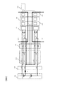
- FIG. 1 is a circuit configuration diagram of the battery monitoring device.
- the assembled battery 200 has a plurality of single cells 210 to 240.
- the cells 210 to 240 are discharged by supplying power to a load (not shown). Further, the cells 210 to 240 are charged with electric power supplied from a charging device (not shown) or the like.
- the connection harness 300 has voltage detection lines 310 to 350.
- the battery monitoring device 400 is connected to the assembled battery 200 via the connection harness 300.
- the assembled battery 200 shows an example in which the single cells 210 to 240 are connected in series. However, the assembled battery 200 may have other configurations such as a series connection of the single cells connected in parallel.
- the number of single cells is not limited.
- the battery monitoring device 400 includes a measurement filter circuit 410, an adjustment circuit 420, and a monitoring circuit 100 corresponding to the upper unit cells 210 to 220 and the lower unit cells 230 to 240, respectively.
- a microcomputer 500 is connected to the monitoring circuit 100.
- the monitoring circuit 100 is a semiconductor integrated circuit including a discharge circuit 110, a voltage measurement circuit 120, a differential amplifier 130, an AD converter 140, and a communication circuit 150, and monitors the state of a single cell.
- the voltage detection lines 310 to 350 have one end connected to the positive and negative electrodes of the cells 210 to 240, respectively, and the other end connected to the voltage measurement circuit 120 via the measurement filter circuit 410.
- the voltage of each single cell measured by the voltage measurement circuit 120 is amplified to an appropriate voltage level by the differential amplifier 130, converted to a digital value by the AD converter 140, and transmitted to the microcomputer 500 from the communication circuit 150.
- the measurement filter circuit 410 is connected to the voltage detection lines 310 to 350 and constitutes a filter circuit composed of a resistor and a measurement filter capacitor.
- the adjustment circuit 420 is a portion branched from the voltage detection lines 310 to 350 and connected to a resistor.
- the discharge circuit 110 is connected to the resistance of the adjustment circuit 420 and includes switch elements 111 to 114.
- the switch elements 111 to 114 are installed between the positive and negative electrodes of the single cells 210 to 240 and are ON / OFF controlled by the voltage measurement circuit 120. For example, when the switch element 112 is turned on for a predetermined time by the voltage measurement circuit 120, the positive electrode and the negative electrode of the single cell 220 are short-circuited via the adjustment circuit 420, and the single cell 220 is discharged. At this time, adjacent switch elements, for example, the switch element 111 are not simultaneously turned ON. *
- FIG. 2 is a circuit diagram of a main part of the battery monitoring device.
- the main circuit configuration diagram shown in FIG. 2 includes two unit cells 220 and 230 adjacent to each other, a connection harness 300 connected to the unit cells 220 and 230, filter resistors for measurement 411, 412, 413, and 414, and measurement.
- Measurement filter circuit 410 composed of filter capacitors 415, 416, and adjustment circuit 420 composed of resistors 421, 422, 423, 424.
- switch elements 112 and 113, a voltage measurement circuit 120, a differential amplifier 130, an AD converter 140, a communication circuit 150, and a microcomputer 500 are included.
- the V1 voltage is a voltage input from the upper unit cell 220 to the voltage measurement circuit 120
- the V2 voltage is a voltage input from the lower unit cell 230 adjacent to the upper unit cell 220 to the voltage measurement circuit 120. is there.
- FIG. 3A and 3B are diagrams showing changes in the V1 voltage and the V2 voltage input to the voltage measurement circuit 120.
- FIG. 3A shows a change in the V1 voltage
- FIG. 3B shows a change in the V2 voltage.
- the disconnection said by this embodiment includes that a voltage detection line becomes high resistance and will be in the state close
- the detection of the disconnection state of the voltage detection line will be described with reference to FIGS.
- the V1 voltage and the V2 voltage are the same as those in FIG.
- the voltages are the same as the voltages of the single cells 220 and 230, respectively, and there is no change.
- the voltage detection line 330 is in a disconnected state at the disconnected point B in FIG. 2
- the low potential side of V1 and the high potential side of V2 are respectively in a floating state. That is, the V1 voltage and the V2 voltage are not determined by the influence of the component characteristic variation and the consumption current variation, as indicated by reference numerals 603 and 604 in FIGS.
- the sum of the V1 voltage and the V2 voltage is always equal to the sum of the voltage of the unit cell 220 and the voltage of the unit cell 230.
- V1 + V2 single cell 220 voltage + single cell 230 voltage (1)
- the measurement filter capacitor 415 When the switch element 112 shown in FIG. 2 is turned on at time t4 for disconnection detection, the measurement filter capacitor 415 is discharged through the measurement filter resistors 411 and 412 and the adjustment resistors 421 and 422. .
- the voltage V1 is changed to 605 in FIG. 3A by the time constant calculated from the capacitance of the measurement filter capacitor 415 and the combined resistance of the resistors 411, 412, 421, and 422.
- the voltage V2 increases as indicated by 606 in FIG. 3B according to the equation (1).
- the disconnection state is detected using the difference between the V1 voltage and the V2 voltage depending on whether the voltage detection line 330 is not in the disconnection state or in the disconnection state. That is, when the value V1_d2 of the V1 voltage after the switch element 112 is turned on at time t4 falls below the low potential side fluctuation threshold, or when the value V2_d2 of the V2 voltage exceeds the high potential side fluctuation threshold, It is determined that 330 is in a disconnected state.
- the low potential side variation threshold value and the high potential side variation threshold value are obtained based on the equations (2) and (3).
- the voltage just before the high potential side in Expression (2) is the voltage V2_b2 immediately before time t4 shown in FIG. 3B, and is the voltage immediately before turning on the switch element 112.
- the voltage immediately before the low potential side in the expression (3) is the voltage V1_b2 immediately before the time t4 shown in FIG. 3A, and is a voltage immediately before the switch element 112 is turned ON.
- ⁇ is a coefficient greater than 0 and less than 1, and an optimal value is set according to the time for which the switch element 112 is turned on and the time constant of the measurement filter capacitor 415.
- High potential side fluctuation threshold High potential side immediately preceding voltage ⁇ (1 + ⁇ ) (2)
- Low potential side fluctuation threshold Low potential side immediately preceding voltage ⁇ (1- ⁇ ) (3)
- the switch element 112 is turned off at time t5, but before this time, the value V1_d2 of the V1 voltage falls below the low potential side fluctuation threshold or the value V2_d2 of the V2 voltage exceeds the high potential side fluctuation threshold, The disconnection state can be detected in a shorter time than the detection using the fixed threshold. Note that, at time t6, an example in which the switch element 112 is turned on for discharge adjustment is shown.
- the disconnection state of the voltage detection line 330 can also be detected by turning on the switch element 113.
- this case will be described with reference to FIGS.
- the switch element 112 is OFF and the switch element 113 is turned ON.
- the measurement filter capacitor 416 is discharged through the measurement filter resistors 413 and 414 and the adjustment resistors 423 and 424.
- the voltage V2 becomes 608 in FIG. 3B by the time constant calculated from the capacitance of the measurement filter capacitor 416 and the combined resistance of the resistors 413, 414, 423, and 424. Decreases as shown.
- the voltage V2 decreases, the V1 voltage increases as indicated by 607 in FIG.
- the high potential side variation threshold and the low potential side variation threshold are obtained based on Equation (2) and Equation (3).
- the voltage just before the high potential side in Expression (2) is the voltage V1_b3 immediately before time t7 shown in FIG.
- the voltage immediately before the low potential side in the equation (3) is the voltage V2_b3 immediately before time t7 shown in FIG.
- the voltage immediately before the low potential side is the value of the V2 voltage or the value of the V1 voltage corresponding to the switch element turned on.
- the voltage immediately before the low potential side is the value of the V2 voltage, and is the voltage V2_b3.
- the voltage immediately before the low potential side is the value of the V1 voltage, which is the voltage V1_b2.
- the voltage just before the high potential side is the value of the V2 voltage or the value of the V1 voltage corresponding to the switch element that is OFF.
- the switch element 113 is turned off at time t8, but before this time, the value V1_d3 of the V1 voltage exceeds the high potential side fluctuation threshold value or the value V2_d3 of the V2 voltage falls below the low potential side fluctuation threshold value.
- the disconnection state can be detected in a shorter time than the detection using the fixed threshold. Note that, at time t9, an example in which the switch element 113 is turned on for discharge adjustment is shown.
- the voltage measurement circuit 120 can measure the V1 voltage and the V2 voltage up to the input range upper limit voltage 710 shown in FIGS. 3A and 3B.
- the input range upper limit voltage 710 is determined by the combination of the AD converter 140 and the differential amplifier 130.
- the monitoring circuit 100 recognizes the input voltage as the input range upper limit voltage 710 voltage.
- the voltage V2_b3 may be lower than the actual V2 voltage, and the low potential side fluctuation threshold calculated by the equation (3) may be set inappropriately low. In this case, the voltage V2_d3 illustrated in FIG. 3B may not fall below the low potential side variation threshold.
- the high potential side variation threshold is set appropriately, and the voltage V1_d3 shown in FIG. When the value exceeds the high potential side fluctuation threshold, a disconnection state is detected.
- the coefficient ⁇ in the expressions (2) and (3) is set inappropriately large, the high potential side fluctuation threshold becomes higher than the input range upper limit voltage, and the voltage V1_d3 shown in FIG.
- the high potential fluctuation threshold cannot be exceeded. Therefore, the coefficient ⁇ is set as follows in consideration of the input range upper limit voltage 710 so that the disconnection state can be detected by at least one of the V1 voltage and the V2 voltage. That is, at least one of the formula (4) and the formula (5) is satisfied when A is in the range of 0 to 1.
- the maximum value of the battery voltage to be used is the maximum value of the voltages of the single cells 220 and 230.
- FIG. 4 is a flowchart of the battery monitoring device that detects the disconnection state of the voltage detection line.
- the detection of the disconnection state of the voltage detection line 330 will be described with reference to FIGS.
- step 801 the switch element 112 and the switch element 113 are turned off.
- step 802 the V1 voltage and the V2 voltage V1_b2 and V2_b2 in the OFF state of the switch element 112 and the switch element 113 are measured immediately before time t4 shown in FIG.
- step 803 the measured voltage V1_b2 is substituted for the voltage immediately before the low potential side in the equation (3) to calculate the low potential side fluctuation threshold. Further, the measured voltage V2_b2 is substituted for the voltage just before the high potential side in the equation (2) to calculate the high potential side variation threshold.
- step 804 the switch element 112 is turned on and the switch element 113 is turned off at time t4 shown in FIG.
- Step 805 waits for a predetermined time. This waiting time is shorter than the time required for detection using a conventional fixed threshold, and is determined by the time constant of the measurement filter capacitor 415.
- step 806 V1 voltage and V2 voltage V1_d2 and V2_d2 are measured.
- step 807 the measured voltage V1_d2 and voltage V2_d2 are compared with the low potential side variation threshold and the high potential side variation threshold calculated in step 803, respectively. If the voltage V1_d2 is smaller than the low potential side variation threshold, or if the voltage V2_d2 is larger than the high potential side variation threshold, it is determined that the circuit is disconnected, and the process proceeds to the next step 808. In step 808, the disconnection counter is incremented. The battery monitoring device 400 determines the disconnection state when the disconnection counter reaches a certain level or more.
- step 807 if the voltage V1_d2 is not smaller than the low potential side variation threshold and the voltage V2_d2 is not larger than the high potential side variation threshold, it is determined that there is no disconnection state, and step 808 is skipped.
- step 809 the switch element 112 is turned OFF at time t5 shown in FIG.
- the above processing is an example in which the switch element 112 is turned on and the disconnection state is detected. However, in the following processing, the switch element 113 is turned on and the disconnection state is detected. This example will be described below with reference to the flowchart shown in FIG.
- step 810 the switch element 112 and the switch element 113 are turned off.
- step 811 the V1 voltage and the V2 voltage V1_b3 and V2_b3 in the OFF state of the switch element 112 and the switch element 113 are measured immediately before time t7 shown in FIG.
- step 812 the measured voltage V2_b3 is substituted for the voltage immediately before the low potential side in the equation (3) to calculate the low potential side variation threshold. Further, the measured voltage V1_b3 is substituted for the voltage immediately before the high potential side in Expression (2) to calculate the high potential side variation threshold.
- step 813 the switch element 112 is turned off and the switch element 113 is turned on at time t7 shown in FIG.
- Step 814 waits for a predetermined time. This waiting time is shorter than the time required for detection using the conventional fixed threshold.
- step 815 the V1 voltage and the V2 voltage V1_d3 and V2_d3 are measured.
- step 816 the measured voltage V1_d3 and voltage V2_d3 are respectively compared with the low potential side variation threshold and the high potential side variation threshold calculated in step 812. If the voltage V1_d3 is larger than the high potential side variation threshold, or if the voltage V2_d3 is smaller than the low potential side variation threshold, it is determined that the circuit is disconnected and the process proceeds to the next step 817.
- step 817 the disconnection counter is incremented. The battery monitoring device determines the disconnection state when the disconnection counter reaches a certain level or more.
- step 816 If it is determined in step 816 that the voltage V1_d3 is not smaller than the low potential side variation threshold and the voltage V2_d3 is not larger than the high potential variation threshold, it is determined that there is no disconnection and step 817 is skipped.
- step 818 the switch element 113 is turned OFF at time t8 shown in FIG.
- the disconnection state of the voltage detection line 330 can be detected by the processing described above.
- the disconnection state may be detected by turning on the switch element 113, or the disconnection state may be detected by turning on the switch element 112.
- the switch element 112 may be turned on to detect a disconnection state, and then the switch element 113 may be turned on to detect the disconnection state. In this case, the disconnection state can be reliably detected.
- the detection of the disconnection state of the voltage detection line 330 has been described. However, the detection of the disconnection state of the voltage detection lines 320 and 340 can be performed in the same manner.
- the disconnection state of the voltage detection lines 310 and 350 can be detected by turning on the switch element 111 or 114.
- a monitoring circuit 100 that is provided corresponding to the assembled battery 200 including a plurality of unit cells 210, 220, 230, and 240 and that monitors the state of the unit cells 210, 220, 230, and 240; 220, 230, 240, voltage detection lines 310, 320, 330, 340, 350 that connect the cells 210, 220, 230, 240 and the monitoring circuit 100, and voltage detection lines 310, 320, 330, 340, 350, and a battery monitoring device 400 that includes switch elements 111, 112, 113, 114 that adjust the voltage of the single cells 210, 220, 230, 240.
- Fluctuation threshold value determined based on the voltage immediately before diagnosing the disconnection state of the battery voltage of the adjacent single cells 210, 220, 230, 240 Comparison detects the disconnection state of the voltage detecting lines 310,320,330,340,350 on the basis of the comparison result. As a result, even when the battery voltage is high, the ON control time of the switch element is shortened, and the disconnection state can be reliably detected.
- the battery monitoring apparatus 400 further includes measurement filter capacitors 415 and 416 connected between the voltage detection lines 310, 320, 330, 340, and 350, and the switch elements 111, 112, 113, and 114 are in a conductive state.
- the battery voltage associated with charging / discharging of the measurement filter capacitors 415 and 416 is compared with the fluctuation threshold value. Thereby, the ON control time of the switch element is shortened, and the disconnection state can be reliably detected.
- the fluctuation threshold value has a high potential side fluctuation threshold value and a low potential side fluctuation threshold value
- the high potential side fluctuation threshold value is a voltage on the high potential side immediately before diagnosing the disconnection state.
- the low-potential-side variation threshold is a low-potential voltage that is a voltage on the low-potential side immediately before diagnosing a disconnection state It is determined based on the following equation (2) based on the immediately preceding voltage and the coefficient ⁇ .
- High potential side fluctuation threshold high potential side immediately preceding voltage ⁇ (1 + ⁇ ) (1)
- Low potential side fluctuation threshold Low potential side immediately preceding voltage ⁇ (1 ⁇ ) (2)
- the coefficient ⁇ is expressed by the following formula (3) or formula (3) or the formula (3) or the formula ( It is a value satisfying at least one of 4).
- the high potential side variation threshold and the low potential side variation threshold can be appropriately set.
- the present invention is not limited to the above-described embodiment, and other forms conceivable within the scope of the technical idea of the present invention are also included in the scope of the present invention as long as the characteristics of the present invention are not impaired. .
- DESCRIPTION OF SYMBOLS 100 Monitoring circuit 110 Discharge circuit 111 Switch element 112 Switch element 113 Switch element 114 Switch element 120 Voltage measurement circuit 130 Differential amplifier 140 AD converter 150 Communication circuit 200 Battery pack 210 Cell 220 Battery 210 Cell 240 Cell 300 Connection Harness 310 Voltage detection line 320 Voltage detection line 330 Voltage detection line 340 Voltage detection line 350 Voltage detection line 400 Battery monitoring device 410 Measurement filter circuit 411 Measurement filter resistance 412 Measurement filter resistance 413 Measurement filter resistance 414 Measurement filter resistance 415 Filter capacitor for measurement 416 Filter capacitor for measurement 420 Adjustment circuit 421 Adjustment resistor 422 Adjustment resistor 423 Adjustment resistor 424 Adjustment resistor 500 Microcomputer
Landscapes
- Engineering & Computer Science (AREA)
- Physics & Mathematics (AREA)
- General Physics & Mathematics (AREA)
- Power Engineering (AREA)
- Manufacturing & Machinery (AREA)
- Chemical & Material Sciences (AREA)
- Chemical Kinetics & Catalysis (AREA)
- Electrochemistry (AREA)
- General Chemical & Material Sciences (AREA)
- Testing Of Short-Circuits, Discontinuities, Leakage, Or Incorrect Line Connections (AREA)
- Charge And Discharge Circuits For Batteries Or The Like (AREA)
- Secondary Cells (AREA)
Abstract
単電池の電池電圧が高電圧であった場合に、検出電圧が固定閾値まで低下するのに時間がかかり、確実に断線を検出する為には、スイッチ素子のON制御の時間が長くなっていた。 複数個の単電池からなる組電池に対応して設けられ、単電池の状態を監視する監視回路と、単電池に対応して設けられ、単電池と監視回路とを接続する電圧検出線と 、電圧検出線の間に設けられ、単電池の電圧を調整するスイッチ素子と、を備える電池監視装置において、電池監視装置は、隣接する単電池の電池電圧を、断線状態を診断する直前の電圧に基づいて決められる変動閾値と比較し、その比較結果に基づいて電圧検出線の断線状態を検出する。
Description
本発明は、電池監視装置に関する。
ハイブリッド自動車(HEV)や電気自動車(EV)などでは、所望の高電圧を確保するため、二次電池により構成される単電池を複数個直並列に接続して構成される組電池(電池システム)が用いられている。このような組電池においては、各単電池の容量計算や保護管理のために、単電池の状態を監視し、充放電を制御する監視回路を備え、この監視回路を用いて各単電池の電圧を調整している。
各単電池と監視回路の間には電圧検出線が設けられているが、電圧検出線に断線が発生すると、単電池の電圧を正確に測定できなくなり、各単電池の電圧を正しく調整できない。特許文献1には、単電池の正極と負極にそれぞれ接続された電圧検出線の間に抵抗を設け、この抵抗を介して単電池を所定時間だけ放電させ、電圧検出線間の検出電圧を固定閾値と比較する装置が記載されている。この装置では、電圧検出線間に抵抗を介して接続されたスイッチ素子をON制御し、電圧検出線間の検出電圧が固定閾値以下であれば断線と診断している。
従来の装置では、単電池の電池電圧が高電圧であった場合に、検出電圧が固定閾値まで低下するのに時間がかかり、確実に断線を検出する為には、スイッチ素子のON制御の時間が長くなっていた。
本発明による電池監視装置は、複数個の単電池からなる組電池に対応して設けられ、単電池の状態を監視する監視回路と、前記単電池に対応して設けられ、前記単電池と前記監視回路とを接続する電圧検出線と、前記電圧検出線の間に設けられ、前記単電池の電圧を調整するスイッチ素子と、を備える電池監視装置において、前記電池監視装置は、隣接する前記単電池の電池電圧を、断線状態を診断する直前の電圧に基づいて決められる変動閾値と比較し、その比較結果に基づいて前記電圧検出線の断線状態を検出する。
本発明によれば、電池電圧が高電圧であっても、スイッチ素子のON制御の時間が短くなり、確実に断線状態を検出することができる。
以下、図面を参照して本発明の一実施形態に係る電池監視装置について説明する。図1は、電池監視装置の回路構成図である。
組電池200は、複数の単電池210~240を有している。単電池210~240は、不図示の負荷に対して電力を供給することで放電される。また、単電池210~240は不図示の充電装置等から供給される電力により充電される。接続ハーネス300は電圧検出線310~350を有している。電池監視装置400は、接続ハーネス300を介して組電池200と接続される。
なお、組電池200は、単電池210~240を直列接続した例を示しているが、組電池200の構成は、単電池を並列に接続したものをさらに直列に接続にするなど、他の構成であってもよく、単電池の個数も限定されない。
電池監視装置400は、上側単電池210~220および下側単電池230~240にそれぞれ対応して、測定用フィルタ回路410、調整回路420、監視回路100を備える。監視回路100にはマイコン500が接続される。
監視回路100は、放電回路110、電圧測定回路120、差動増幅器130、AD変換器140、通信回路150を備えた半導体集積回路であり、単電池の状態を監視する。
電圧検出線310~350は、一端はそれぞれ単電池210~240の正極と負極に接続され、他端はそれぞれ測定用フィルタ回路410を介して電圧測定回路120と接続される。電圧測定回路120で測定された各単電池の電圧は、差動増幅器130により適切な電圧レベルに増幅され、AD変換器140でデジタル値に変換され、通信回路150よりマイコン500に送信される。
測定用フィルタ回路410は、電圧検出線310~350に接続され、抵抗と測定用フィルタコンデンサとよりなるフィルタ回路を構成する。調整回路420は、電圧検出線310~350から分岐して抵抗が接続される部分である。
放電回路110は、調整回路420の抵抗に接続され、スイッチ素子111~114を有する。スイッチ素子111~114は、単電池210~240の正極と負極の間に設置され、電圧測定回路120によりON-OFF制御される。例えば、電圧測定回路120によってスイッチ素子112が所定の時間ONされると、単電池220の正極と負極が、調整回路420を介して短絡し、単電池220が放電される。この時、隣接するスイッチ素子、例えばスイッチ素子111が同時にONすることは無い。
図2は、電池監視装置の要部回路構成図である。
図2に示す要部回路構成図は、互いに隣接する2つの単電池220、230と、単電池220、230に接続される接続ハーネス300と、測定用フィルタ抵抗411、412、413、414と測定用フィルタコンデンサ415、416より構成される測定用フィルタ回路410と、抵抗421、422、423、424より構成される調整回路420とを有する。更に、図1と同様に、スイッチ素子112、113と、電圧測定回路120、差動増幅器130、AD変換器140、通信回路150、マイコン500を有する。
図2に示す要部回路構成図は、互いに隣接する2つの単電池220、230と、単電池220、230に接続される接続ハーネス300と、測定用フィルタ抵抗411、412、413、414と測定用フィルタコンデンサ415、416より構成される測定用フィルタ回路410と、抵抗421、422、423、424より構成される調整回路420とを有する。更に、図1と同様に、スイッチ素子112、113と、電圧測定回路120、差動増幅器130、AD変換器140、通信回路150、マイコン500を有する。
図2において、V1電圧は上側単電池220から電圧測定回路120へ入力される電圧であり、V2電圧は上側単電池220に隣接する下側単電池230から電圧測定回路120へ入力される電圧である。
図3(a)(b)は、電圧測定回路120へ入力されるV1電圧およびV2電圧の変化を示す図である。図3(a)は、V1電圧の変化を、図3(b)は、V2電圧の変化を示すもので、図2に示す電圧検出線330が断線箇所Bで断線した場合の例である。なお、本実施形態で言う断線とは、電圧検出線が高抵抗となり断線に近い状態になることも含み、以下、断線状態と称する。
以下、図2、図3を参照して、電圧検出線の断線状態の検出について説明する。
まず、電圧検出線330が断線状態でない場合は、図3(a)(b)の時刻t1、t2でスイッチ素子113をON、OFFしても、V1電圧とV2電圧は、図3(a)(b)の601、602に示すように、それぞれ単電池220、230の電圧と同じ電圧になり変化がない。
まず、電圧検出線330が断線状態でない場合は、図3(a)(b)の時刻t1、t2でスイッチ素子113をON、OFFしても、V1電圧とV2電圧は、図3(a)(b)の601、602に示すように、それぞれ単電池220、230の電圧と同じ電圧になり変化がない。
次に、電圧検出線330が図2の断線箇所Bにおいて断線状態であった場合を説明する。この場合は、断線した時刻t3から、V1の低電位側とV2の高電位側がそれぞれフローティング状態になる。すなわち、V1電圧とV2電圧は、図3(a)(b)の603、604に示すように、部品の特性ばらつきや消費電流ばらつきの影響を受けて定まらない。ただし、この場合も、次式(1)に示すように、V1電圧とV2電圧の合計は、単電池220の電圧と単電池230の電圧の合計に常に等しくなる。
V1+V2=単電池220電圧+単電池230電圧 ・・・(1)
V1+V2=単電池220電圧+単電池230電圧 ・・・(1)
そして、断線検出の為に時刻t4で、図2に示すスイッチ素子112をONにすると測定用フィルタコンデンサ415は、測定用フィルタ抵抗411、412と、調整用抵抗421、422を介して放電される。測定用フィルタコンデンサ415が放電されると、V1電圧は測定用フィルタコンデンサ415の静電容量と抵抗411、412、421、422の合成抵抗から計算される時定数により、図3(a)の605に示すように低下する。電圧V1が低下すると、式(1)に従い電圧V2が図3(b)の606に示すように上昇する。
本実施形態では、電圧検出線330が断線状態にない場合と断線状態である場合とで、V1電圧とV2電圧の違いを利用して断線状態を検出する。すなわち、時刻t4でスイッチ素子112をONした後のV1電圧の値V1_d2が低電位側変動閾値を下回った場合、またはV2電圧の値V2_d2が高電位側変動閾値を上回った場合に、電圧検出線330が断線状態であると判断する。
低電位側変動閾値と高電位側変動閾値は、式(2)、式(3)に基づいて求める。式(2)の高電位側直前電圧は、図3(b)に示す時刻t4の直前の電圧V2_b2であり、スイッチ素子112をONする直前の電圧である。また、式(3)の低電位側直前電圧は、図3(a)に示す時刻t4の直前の電圧V1_b2であり、スイッチ素子112をONする直前の電圧である。αは0より大きく、1未満の係数であり、スイッチ素子112をONする時間と、測定用フィルタコンデンサ415の時定数により最適な値を設定する。
高電位側変動閾値=高電位側直前電圧×(1+α) ・・(2)
低電位側変動閾値=低電位側直前電圧×(1-α) ・・(3)
高電位側変動閾値=高電位側直前電圧×(1+α) ・・(2)
低電位側変動閾値=低電位側直前電圧×(1-α) ・・(3)
スイッチ素子112は、時刻t5でOFFするが、この時刻になる以前に、V1電圧の値V1_d2が低電位側変動閾値を下回る、またはV2電圧の値V2_d2が高電位側変動閾値を上回り、従来の固定閾値を用いた検出よりも短時間で断線状態の検出が可能になる。なお、時刻t6は放電調整のためにスイッチ素子112がONされた場合の例を示した。
次に、電圧検出線330の断線状態の検出は、スイッチ素子113をONすることによっても可能である。以下、この場合について図3(a)(b)を参照して説明する。
電圧検出線330が時刻t3で断線状態になった後、時刻t7で、スイッチ素子112はOFF状態で、スイッチ素子113をONにする。その結果、測定用フィルタコンデンサ416は、測定用フィルタ抵抗413、414と、調整用抵抗423、424を介して放電される。測定用フィルタコンデンサ416が放電されると、V2電圧は測定用フィルタコンデンサ416の静電容量と抵抗413、414、423、424の合成抵抗から計算される時定数により図3(b)の608に示すように低下する。電圧V2が低下すると、式(1)に従いV1電圧が図3(a)の607に示すように上昇する。
電圧検出線330が時刻t3で断線状態になった後、時刻t7で、スイッチ素子112はOFF状態で、スイッチ素子113をONにする。その結果、測定用フィルタコンデンサ416は、測定用フィルタ抵抗413、414と、調整用抵抗423、424を介して放電される。測定用フィルタコンデンサ416が放電されると、V2電圧は測定用フィルタコンデンサ416の静電容量と抵抗413、414、423、424の合成抵抗から計算される時定数により図3(b)の608に示すように低下する。電圧V2が低下すると、式(1)に従いV1電圧が図3(a)の607に示すように上昇する。
すなわち、時刻t7でスイッチ素子113をONした後のV1電圧の値V1_d3が高電位側変動閾値を上回った場合、またはV2電圧の値V2_d3が低電位側変動閾値を下回った場合に、断線状態と判断する。
高電位側変動閾値と低電位側変動閾値は、式(2)、式(3)に基づいて求める。式(2)の高電位側直前電圧は、図3(a)に示す時刻t7の直前の電圧V1_b3である。また、式(3)の低電位側直前電圧は、図3(b)に示す時刻t7の直前の電圧V2_b3である。
なお、低電位側直前電圧は、ONにしたスイッチ素子に対応するV2電圧の値またはV1電圧の値である。具体的には、スイッチ素子113をONした場合は、低電位側直前電圧はV2電圧の値であり、電圧V2_b3である。スイッチ素子112をONした場合は、低電位側直前電圧はV1電圧の値であり、電圧V1_b2である。高電位側直前電圧は、OFFになっているスイッチ素子に対応するV2電圧の値またはV1電圧の値である。
スイッチ素子113は、時刻t8でOFFするが、この時刻になる以前に、V1電圧の値V1_d3が高電位側変動閾値を上回る、またはV2電圧の値V2_d3が低電位側変動閾値を下回り、従来の固定閾値を用いた検出よりも短時間で断線状態の検出が可能になる。なお、時刻t9は放電調整のためにスイッチ素子113がONされた場合の例を示した。
なお、電圧測定回路120によるV1電圧およびV2電圧の測定は、図3(a)(b)に示す入力範囲上限電圧710まで可能である。入力範囲上限電圧710は、AD変換器140と差動増幅器130の組み合わせにより決まる。監視回路100は、入力範囲上限電圧710より高いV1電圧、V2電圧が入力された場合は、この入力された電圧を入力範囲上限電圧710の電圧として認識する。例えば、図3(b)の608に示すように電圧V2_b3が実際のV2電圧よりも低くなり、式(3)で算出される低電位側変動閾値が不適切に低く設定される場合がある。この場合、図3(b)に示す電圧V2_d3が低電位側変動閾値を下回らないことがある。しかし、式(1)により、図3(a)に示す電圧V1_b3は必ず入力範囲上限電圧710より下であるため、高電位側変動閾値は適切に設定され、図3(a)に示す電圧V1_d3が高電位側変動閾値を上回ることで断線状態が検出される。
この場合、式(2)、式(3)の係数αを不適切に大きく設定すると、高電位側変動閾値が入力範囲上限電圧よりも高くなってしまい、図3(a)に示す電圧V1_d3が高電位側変動閾値を上回ることができない。よって係数αは、V1電圧、またはV2電圧の少なくともどちらか一方で断線状態が検出できるように、入力範囲上限電圧710を考慮して以下のように設定する。すなわち、Aが0以上1以下の範囲において、式(4)、または式(5)のどちらか少なくとも一方を満たす。ここで、使用する電池電圧の最大値は単電池220、230の電圧の最大値である。
(使用する電池電圧の最大値)×2 ×A≦(入力範囲上限電圧) ・・(4)
(使用する電池電圧の最大値)×2×(1-A)×(1 + α)≦(入力範囲上限電圧) ・・(5)
(使用する電池電圧の最大値)×2 ×A≦(入力範囲上限電圧) ・・(4)
(使用する電池電圧の最大値)×2×(1-A)×(1 + α)≦(入力範囲上限電圧) ・・(5)
図4は、電圧検出線の断線状態を検出する電池監視装置のフローチャートである。図3、図4を参照して、電圧検出線330の断線状態の検出について説明する。
ステップ801で、スイッチ素子112とスイッチ素子113をOFF状態にする。次に、ステップ802で、スイッチ素子112とスイッチ素子113のOFF状態におけるV1電圧とV2電圧であるV1_b2とV2_b2を、図3に示す時刻t4の直前で測定する。
ステップ801で、スイッチ素子112とスイッチ素子113をOFF状態にする。次に、ステップ802で、スイッチ素子112とスイッチ素子113のOFF状態におけるV1電圧とV2電圧であるV1_b2とV2_b2を、図3に示す時刻t4の直前で測定する。
ステップ803で、測定した電圧V1_b2を式(3)の低電位側直前電圧に代入して、低電位側変動閾値を算出する。さらに、測定した電圧V2_b2を式(2)の高電位側直前電圧に代入して高電位側変動閾値を算出する。
次に、ステップ804において、図3に示す時刻t4でスイッチ素子112をONにし、スイッチ素子113をOFFにする。ステップ805で、所定の時間待機する。この待ち時間は従来の固定閾値を用いた検出に要する時間よりも短時間であり、測定用フィルタコンデンサ415の時定数により決められる時間である。次に、時刻t5になる前に、ステップ806で、V1電圧とV2電圧であるV1_d2とV2_d2を測定する。
ステップ807で、測定した電圧V1_d2と電圧V2_d2を、ステップ803で算出した低電位側変動閾値と高電位側変動閾値とそれぞれ比較する。電圧V1_d2が低電位側変動閾値より小さければ、または電圧V2_d2が高電位側変動閾値より大きければ断線状態と判断して次のステップ808へ進む。ステップ808では、断線カウンタを増加させる。電池監視装置400は、断線カウンタが一定以上に達した場合に、断線状態を確定する。ステップ807で、電圧V1_d2が低電位側変動閾値より小さくなく、かつ電圧V2_d2が高電位側変動閾値より大きくなければ、断線状態ではないと判断してステップ808をスキップする。ステップ809において、図3に示す時刻t5でスイッチ素子112をOFFにする。
以上の処理では、スイッチ素子112をONにして断線状態を検出する例であるが、以下の処理ではスイッチ素子113をONにして断線状態を検出する。以下、この例について図4に示すフローチャートを参照して説明する。
まず、ステップ810で、スイッチ素子112とスイッチ素子113をOFF状態にする。次に、ステップ811で、スイッチ素子112とスイッチ素子113のOFF状態におけるV1電圧とV2電圧であるV1_b3とV2_b3を、図3に示す時刻t7の直前で測定する。
ステップ812で、測定した電圧V2_b3を式(3)の低電位側直前電圧に代入して、低電位側変動閾値を算出する。さらに、測定した電圧V1_b3を式(2)の高電位側直前電圧に代入して高電位側変動閾値を算出する。
次に、ステップ813において、図3に示す時刻t7でスイッチ素子112をOFFにし、スイッチ素子113をONにする。ステップ814で、所定の時間待機する。この待ち時間は従来の固定閾値を用いた検出に要する時間よりも短時間である。次に、時刻t8になる前に、ステップ815で、V1電圧とV2電圧であるV1_d3とV2_d3を測定する。
ステップ816で、測定した電圧V1_d3と電圧V2_d3を、ステップ812で算出した低電位側変動閾値と高電位側変動閾値とそれぞれ比較する。電圧V1_d3が高電位側変動閾値より大きければ、または電圧V2_d3が低電位側変動閾値より小さければ断線状態と判断して次のステップ817へ進む。ステップ817では、断線カウンタを増加させる。電池監視装置は、断線カウンタが一定以上に達した場合に、断線状態を確定する。ステップ816で、電圧V1_d3が低電位側変動閾値より小さくなく、かつ電圧V2_d3が高電位側変動閾値より大きくなければ、断線状態ではないと判断してステップ817をスキップする。ステップ818において、図3に示す時刻t8でスイッチ素子113をOFFにする。
以上説明した処理で、電圧検出線330の断線状態を検出することができる。このように、スイッチ素子113をONにして断線状態を検出してもよく、またはスイッチ素子112をONにして断線状態を検出してもよい。または、図4のフローチャートに示すように、スイッチ素子112をONにして断線状態を検出し、続いてスイッチ素子113をONにして断線状態を検出してもよい。この場合は、断線状態を確実に検出することができる。
以上の説明では、電圧検出線330の断線状態の検出について説明したが、電圧検出線320、340の断線状態の検出も同様に行うことができる。また、電圧検出線310、350の断線状態は、スイッチ素子111または114をONにして検出することができる。
以上説明した実施形態によれば、次の作用効果が得られる。
(1)複数個の単電池210、220、230、240からなる組電池200に対応して設けられ、単電池210、220、230、240の状態を監視する監視回路100と、単電池210、220、230、240に対応して設けられ、単電池210、220、230、240と監視回路100とを接続する電圧検出線310、320、330、340、350と、電圧検出線310、320、330、340、350の間に設けられ、単電池210、220、230、240の電圧を調整するスイッチ素子111、112、113、114と、を備える電池監視装置400において、電池監視装置400は、隣接する単電池210、220、230、240の電池電圧を、断線状態を診断する直前の電圧に基づいて決められる変動閾値と比較し、その比較結果に基づいて電圧検出線310、320、330、340、350の断線状態を検出する。これにより、電池電圧が高電圧であっても、スイッチ素子のON制御の時間が短くなり、確実に断線状態を検出することができる。
(1)複数個の単電池210、220、230、240からなる組電池200に対応して設けられ、単電池210、220、230、240の状態を監視する監視回路100と、単電池210、220、230、240に対応して設けられ、単電池210、220、230、240と監視回路100とを接続する電圧検出線310、320、330、340、350と、電圧検出線310、320、330、340、350の間に設けられ、単電池210、220、230、240の電圧を調整するスイッチ素子111、112、113、114と、を備える電池監視装置400において、電池監視装置400は、隣接する単電池210、220、230、240の電池電圧を、断線状態を診断する直前の電圧に基づいて決められる変動閾値と比較し、その比較結果に基づいて電圧検出線310、320、330、340、350の断線状態を検出する。これにより、電池電圧が高電圧であっても、スイッチ素子のON制御の時間が短くなり、確実に断線状態を検出することができる。
(2)電池監視装置400は、電圧検出線310、320、330、340、350の間に接続される測定用フィルタコンデンサ415、416をさらに備え、スイッチ素子111、112、113、114を導通状態にすることにより、測定用フィルタコンデンサ415、416の充放電に伴う電池電圧を変動閾値と比較する。これにより、スイッチ素子のON制御の時間が短くなり、確実に断線状態を検出することができる。
(3)電池監視装置400において、変動閾値は、高電位側変動閾値と、低電位側変動閾値とを有し、高電位側変動閾値は、断線状態を診断する直前の高電位側の電圧である高電位側直前電圧と係数α(0<α<1)に基づく下記式(1)に基づいて、低電位側変動閾値は、断線状態を診断する直前の低電位側の電圧である低電位側直前電圧と係数αに基づく下記式(2)に基づいて決定する。
高電位側変動閾値=高電位側直前電圧×(1+α) ・・(1)
低電位側変動閾値=低電位側直前電圧×(1-α) ・・(2)
これにより、従来の固定閾値に比較して、短時間で断線状態を検出することができる。
高電位側変動閾値=高電位側直前電圧×(1+α) ・・(1)
低電位側変動閾値=低電位側直前電圧×(1-α) ・・(2)
これにより、従来の固定閾値に比較して、短時間で断線状態を検出することができる。
(4)電池監視装置400において、係数αは、監視回路100が測定可能な上限電圧である入力範囲上限電圧と、0以上1以下のAとの関係において、下記式(3)、または式(4)の少なくとも一方を満たす値である。
(使用する電池電圧の最大値)×2 ×A≦(入力範囲上限電圧) ・・(3)
(使用する電池電圧の最大値)×2×(1-A)×(1 + α)≦(入力範囲上限電圧) ・・(4)
これにより、高電位側変動閾値と、低電位側変動閾値とを適切に設定することができる。
(使用する電池電圧の最大値)×2 ×A≦(入力範囲上限電圧) ・・(3)
(使用する電池電圧の最大値)×2×(1-A)×(1 + α)≦(入力範囲上限電圧) ・・(4)
これにより、高電位側変動閾値と、低電位側変動閾値とを適切に設定することができる。
本発明は、上記の実施形態に限定されるものではなく、本発明の特徴を損なわない限り、本発明の技術思想の範囲内で考えられるその他の形態についても、本発明の範囲内に含まれる。
100 監視回路
110 放電回路
111 スイッチ素子
112 スイッチ素子
113 スイッチ素子
114 スイッチ素子
120 電圧測定回路
130 差動増幅器
140 AD変換器
150 通信回路
200 組電池
210 単電池
220 単電池
230 単電池
240 単電池
300 接続ハーネス
310 電圧検出線
320 電圧検出線
330 電圧検出線
340 電圧検出線
350 電圧検出線
400 電池監視装置
410 測定用フィルタ回路
411 測定用フィルタ抵抗
412 測定用フィルタ抵抗
413 測定用フィルタ抵抗
414 測定用フィルタ抵抗
415 測定用フィルタコンデンサ
416 測定用フィルタコンデンサ
420 調整回路
421 調整用抵抗
422 調整用抵抗
423 調整用抵抗
424 調整用抵抗
500 マイコン
Claims (4)
- 複数個の単電池からなる組電池に対応して設けられ、単電池の状態を監視する監視回路と、前記単電池に対応して設けられ、前記単電池と前記監視回路とを接続する電圧検出線と、前記電圧検出線の間に設けられ、前記単電池の電圧を調整するスイッチ素子と、を備える電池監視装置において、
前記電池監視装置は、隣接する前記単電池の電池電圧を、断線状態を診断する直前の電圧に基づいて決められる変動閾値と比較し、その比較結果に基づいて前記電圧検出線の断線状態を検出する電池監視装置。 - 請求項1に記載の電池監視装置において、
前記電圧検出線の間に接続されるコンデンサをさらに備え、
前記スイッチ素子を導通状態にすることにより、前記コンデンサの充放電に伴う前記電池電圧を前記変動閾値と比較する電池監視装置。 - 請求項1または請求項2に記載の電池監視装置において、
前記変動閾値は、高電位側変動閾値と、低電位側変動閾値とを有し、前記高電位側変動閾値は、断線状態を診断する直前の高電位側の電圧である高電位側直前電圧と係数α(0<α<1)に基づく下記式(1)に基づいて、前記低電位側変動閾値は、断線状態を診断する直前の低電位側の電圧である低電位側直前電圧と前記係数αに基づく下記式(2)に基づいて決定する電池監視装置。
高電位側変動閾値=高電位側直前電圧×(1+α) ・・(1)
低電位側変動閾値=低電位側直前電圧×(1-α) ・・(2) - 請求項3に記載の電池監視装置において、
前記係数αは、前記監視回路が測定可能な上限電圧である入力範囲上限電圧と、0以上1以下のAとの関係において、下記式(3)、または式(4)の少なくとも一方を満たす値である電池監視装置。
(使用する電池電圧の最大値)×2 ×A≦(入力範囲上限電圧) ・・(3)
(使用する電池電圧の最大値)×2×(1-A)×(1 + α)≦(入力範囲上限電圧) ・・(4)
Priority Applications (2)
| Application Number | Priority Date | Filing Date | Title |
|---|---|---|---|
| JP2019525195A JP6853884B2 (ja) | 2017-06-14 | 2018-05-08 | 電池監視装置 |
| US16/619,397 US11249139B2 (en) | 2017-06-14 | 2018-05-08 | Battery monitoring system |
Applications Claiming Priority (2)
| Application Number | Priority Date | Filing Date | Title |
|---|---|---|---|
| JP2017-117182 | 2017-06-14 | ||
| JP2017117182 | 2017-06-14 |
Publications (1)
| Publication Number | Publication Date |
|---|---|
| WO2018230187A1 true WO2018230187A1 (ja) | 2018-12-20 |
Family
ID=64661000
Family Applications (1)
| Application Number | Title | Priority Date | Filing Date |
|---|---|---|---|
| PCT/JP2018/017697 WO2018230187A1 (ja) | 2017-06-14 | 2018-05-08 | 電池監視装置 |
Country Status (3)
| Country | Link |
|---|---|
| US (1) | US11249139B2 (ja) |
| JP (1) | JP6853884B2 (ja) |
| WO (1) | WO2018230187A1 (ja) |
Cited By (2)
| Publication number | Priority date | Publication date | Assignee | Title |
|---|---|---|---|---|
| CN110441697A (zh) * | 2019-08-30 | 2019-11-12 | 浙江八达电子仪表有限公司 | 一种快速检测电能表锂电池电量的装置 |
| JP2021009032A (ja) * | 2019-06-28 | 2021-01-28 | 株式会社デンソーテン | 断線検知装置および断線検知方法 |
Families Citing this family (2)
| Publication number | Priority date | Publication date | Assignee | Title |
|---|---|---|---|---|
| JP6860072B2 (ja) * | 2017-06-16 | 2021-04-14 | 工機ホールディングス株式会社 | 電池パック及び電池パックを用いた電気機器 |
| CN113311342A (zh) * | 2021-05-28 | 2021-08-27 | 中国电力科学研究院有限公司 | 一种锂离子电池热失控监测系统及方法 |
Citations (4)
| Publication number | Priority date | Publication date | Assignee | Title |
|---|---|---|---|---|
| JP2010256155A (ja) * | 2009-04-24 | 2010-11-11 | Yazaki Corp | 断線検出装置 |
| JP2012122856A (ja) * | 2010-12-08 | 2012-06-28 | Toshiba Corp | 組電池装置 |
| JP2014102127A (ja) * | 2012-11-19 | 2014-06-05 | Denso Corp | 電池監視装置 |
| JP2016152720A (ja) * | 2015-02-18 | 2016-08-22 | 三菱電機株式会社 | セルバランス回路及びその故障診断装置 |
Family Cites Families (11)
| Publication number | Priority date | Publication date | Assignee | Title |
|---|---|---|---|---|
| JP3956932B2 (ja) * | 2003-11-07 | 2007-08-08 | ソニー株式会社 | 充電器および充電状態判定方法 |
| KR100812760B1 (ko) * | 2005-12-08 | 2008-03-12 | 김득수 | 축전지 내부 임피던스 유효성분 측정연산 장치 및 그 방법 |
| JP5469813B2 (ja) * | 2008-01-29 | 2014-04-16 | 株式会社日立製作所 | 車両用電池システム |
| JP5486780B2 (ja) * | 2008-07-01 | 2014-05-07 | 株式会社日立製作所 | 電池システム |
| US8629687B2 (en) | 2009-04-24 | 2014-01-14 | Yazaki Corporation | Disconnection detecting device |
| US9411004B2 (en) * | 2014-05-28 | 2016-08-09 | Ford Global Technologies, Llc | Continuous leakage detection circuit with integrated robustness check and balanced fault detection |
| WO2016051684A1 (ja) * | 2014-09-29 | 2016-04-07 | パナソニックIpマネジメント株式会社 | 蓄電セル制御装置および蓄電モジュールマネジメントシステム |
| DE102015117171B4 (de) * | 2014-10-09 | 2019-03-21 | Denso Corporation | Batteriezustandsabschätzvorrichtung |
| JP6402597B2 (ja) | 2014-11-12 | 2018-10-10 | 株式会社Gsユアサ | 組電池の監視装置、蓄電装置、断線診断方法 |
| JP2018038097A (ja) * | 2015-01-16 | 2018-03-08 | パナソニックIpマネジメント株式会社 | 蓄電池制御システム |
| US10644529B2 (en) * | 2016-02-05 | 2020-05-05 | Guangdong Oppo Mobile Telecommunications Corp., Ltd. | Adapter and method for charging control |
-
2018
- 2018-05-08 US US16/619,397 patent/US11249139B2/en active Active
- 2018-05-08 WO PCT/JP2018/017697 patent/WO2018230187A1/ja active Application Filing
- 2018-05-08 JP JP2019525195A patent/JP6853884B2/ja active Active
Patent Citations (4)
| Publication number | Priority date | Publication date | Assignee | Title |
|---|---|---|---|---|
| JP2010256155A (ja) * | 2009-04-24 | 2010-11-11 | Yazaki Corp | 断線検出装置 |
| JP2012122856A (ja) * | 2010-12-08 | 2012-06-28 | Toshiba Corp | 組電池装置 |
| JP2014102127A (ja) * | 2012-11-19 | 2014-06-05 | Denso Corp | 電池監視装置 |
| JP2016152720A (ja) * | 2015-02-18 | 2016-08-22 | 三菱電機株式会社 | セルバランス回路及びその故障診断装置 |
Cited By (5)
| Publication number | Priority date | Publication date | Assignee | Title |
|---|---|---|---|---|
| JP2021009032A (ja) * | 2019-06-28 | 2021-01-28 | 株式会社デンソーテン | 断線検知装置および断線検知方法 |
| EP3839538A4 (en) * | 2019-06-28 | 2022-06-22 | Denso Ten Limited | DISCONNECTION DETECTION DEVICE AND DISCONNECTION DETECTION METHOD |
| JP7240972B2 (ja) | 2019-06-28 | 2023-03-16 | 株式会社デンソーテン | 断線検知装置および断線検知方法 |
| US11909233B2 (en) | 2019-06-28 | 2024-02-20 | Denso Ten Limited | Disconnection detection device and disconnection detection method |
| CN110441697A (zh) * | 2019-08-30 | 2019-11-12 | 浙江八达电子仪表有限公司 | 一种快速检测电能表锂电池电量的装置 |
Also Published As
| Publication number | Publication date |
|---|---|
| JP6853884B2 (ja) | 2021-03-31 |
| JPWO2018230187A1 (ja) | 2020-03-19 |
| US20200124677A1 (en) | 2020-04-23 |
| US11249139B2 (en) | 2022-02-15 |
Similar Documents
| Publication | Publication Date | Title |
|---|---|---|
| US8489347B2 (en) | Battery pack monitoring apparatus | |
| WO2018230187A1 (ja) | 電池監視装置 | |
| US9564768B2 (en) | Discharge device for electricity storage device | |
| US8841915B2 (en) | Battery voltage monitoring apparatus | |
| US8680814B2 (en) | Battery charger and battery charging method | |
| JP5326973B2 (ja) | 電池監視装置 | |
| US20100134069A1 (en) | Battery system with practical voltage detection | |
| WO2014045567A1 (ja) | 電源装置及びこの電源装置を備える電動車両並びに蓄電装置 | |
| JP5974849B2 (ja) | 電池監視装置 | |
| US9863993B2 (en) | Storage battery monitoring device with wiring disconnection detection | |
| US9466993B2 (en) | Charge and discharge control circuit having an intermediate terminal disconnection detecting circuit for detecting disconnection with secondary batteries | |
| JP2015177555A (ja) | 電池監視装置 | |
| WO2013161512A1 (ja) | 充電制御装置および充電制御方法 | |
| JP2012016174A (ja) | 車両用の電源装置 | |
| CN107110895B (zh) | 内置状态监视部的集成电路以及电源装置 | |
| JP4693761B2 (ja) | 組電池システム | |
| JP6787705B2 (ja) | 異常検出装置、および組電池システム | |
| US11824392B2 (en) | Battery pack | |
| CN106936175B (zh) | 充放电控制电路及电池装置 | |
| JP2014112039A (ja) | 検知装置 | |
| JP2017158269A (ja) | 電圧検出装置 | |
| JP2016085128A (ja) | 電池電圧監視半導体装置及び電池電圧監視システム | |
| JP2013179751A (ja) | 組電池の制御装置 | |
| JP4789669B2 (ja) | 車両用の電源装置とこの電源装置の基準接続ラインの断線を検出する方法 | |
| JP5962558B2 (ja) | 電池監視装置 |
Legal Events
| Date | Code | Title | Description |
|---|---|---|---|
| 121 | Ep: the epo has been informed by wipo that ep was designated in this application |
Ref document number: 18816495 Country of ref document: EP Kind code of ref document: A1 |
|
| ENP | Entry into the national phase |
Ref document number: 2019525195 Country of ref document: JP Kind code of ref document: A |
|
| NENP | Non-entry into the national phase |
Ref country code: DE |
|
| 122 | Ep: pct application non-entry in european phase |
Ref document number: 18816495 Country of ref document: EP Kind code of ref document: A1 |