WO2018230036A1 - Dispositif de sécurité - Google Patents
Dispositif de sécurité Download PDFInfo
- Publication number
- WO2018230036A1 WO2018230036A1 PCT/JP2018/005198 JP2018005198W WO2018230036A1 WO 2018230036 A1 WO2018230036 A1 WO 2018230036A1 JP 2018005198 W JP2018005198 W JP 2018005198W WO 2018230036 A1 WO2018230036 A1 WO 2018230036A1
- Authority
- WO
- WIPO (PCT)
- Prior art keywords
- detection
- arm
- collision
- area
- moving part
- Prior art date
Links
Images


Classifications
-
- B—PERFORMING OPERATIONS; TRANSPORTING
- B25—HAND TOOLS; PORTABLE POWER-DRIVEN TOOLS; MANIPULATORS
- B25J—MANIPULATORS; CHAMBERS PROVIDED WITH MANIPULATION DEVICES
- B25J19/00—Accessories fitted to manipulators, e.g. for monitoring, for viewing; Safety devices combined with or specially adapted for use in connection with manipulators
- B25J19/02—Sensing devices
- B25J19/021—Optical sensing devices
- B25J19/023—Optical sensing devices including video camera means
-
- B—PERFORMING OPERATIONS; TRANSPORTING
- B25—HAND TOOLS; PORTABLE POWER-DRIVEN TOOLS; MANIPULATORS
- B25J—MANIPULATORS; CHAMBERS PROVIDED WITH MANIPULATION DEVICES
- B25J13/00—Controls for manipulators
- B25J13/08—Controls for manipulators by means of sensing devices, e.g. viewing or touching devices
- B25J13/081—Touching devices, e.g. pressure-sensitive
-
- B—PERFORMING OPERATIONS; TRANSPORTING
- B25—HAND TOOLS; PORTABLE POWER-DRIVEN TOOLS; MANIPULATORS
- B25J—MANIPULATORS; CHAMBERS PROVIDED WITH MANIPULATION DEVICES
- B25J19/00—Accessories fitted to manipulators, e.g. for monitoring, for viewing; Safety devices combined with or specially adapted for use in connection with manipulators
- B25J19/06—Safety devices
-
- B—PERFORMING OPERATIONS; TRANSPORTING
- B25—HAND TOOLS; PORTABLE POWER-DRIVEN TOOLS; MANIPULATORS
- B25J—MANIPULATORS; CHAMBERS PROVIDED WITH MANIPULATION DEVICES
- B25J9/00—Programme-controlled manipulators
- B25J9/16—Programme controls
- B25J9/1628—Programme controls characterised by the control loop
- B25J9/1651—Programme controls characterised by the control loop acceleration, rate control
-
- B—PERFORMING OPERATIONS; TRANSPORTING
- B25—HAND TOOLS; PORTABLE POWER-DRIVEN TOOLS; MANIPULATORS
- B25J—MANIPULATORS; CHAMBERS PROVIDED WITH MANIPULATION DEVICES
- B25J9/00—Programme-controlled manipulators
- B25J9/16—Programme controls
- B25J9/1674—Programme controls characterised by safety, monitoring, diagnostic
- B25J9/1676—Avoiding collision or forbidden zones
-
- F—MECHANICAL ENGINEERING; LIGHTING; HEATING; WEAPONS; BLASTING
- F16—ENGINEERING ELEMENTS AND UNITS; GENERAL MEASURES FOR PRODUCING AND MAINTAINING EFFECTIVE FUNCTIONING OF MACHINES OR INSTALLATIONS; THERMAL INSULATION IN GENERAL
- F16P—SAFETY DEVICES IN GENERAL; SAFETY DEVICES FOR PRESSES
- F16P3/00—Safety devices acting in conjunction with the control or operation of a machine; Control arrangements requiring the simultaneous use of two or more parts of the body
- F16P3/12—Safety devices acting in conjunction with the control or operation of a machine; Control arrangements requiring the simultaneous use of two or more parts of the body with means, e.g. feelers, which in case of the presence of a body part of a person in or near the danger zone influence the control or operation of the machine
- F16P3/14—Safety devices acting in conjunction with the control or operation of a machine; Control arrangements requiring the simultaneous use of two or more parts of the body with means, e.g. feelers, which in case of the presence of a body part of a person in or near the danger zone influence the control or operation of the machine the means being photocells or other devices sensitive without mechanical contact
- F16P3/141—Safety devices acting in conjunction with the control or operation of a machine; Control arrangements requiring the simultaneous use of two or more parts of the body with means, e.g. feelers, which in case of the presence of a body part of a person in or near the danger zone influence the control or operation of the machine the means being photocells or other devices sensitive without mechanical contact using sound propagation, e.g. sonar
-
- F—MECHANICAL ENGINEERING; LIGHTING; HEATING; WEAPONS; BLASTING
- F16—ENGINEERING ELEMENTS AND UNITS; GENERAL MEASURES FOR PRODUCING AND MAINTAINING EFFECTIVE FUNCTIONING OF MACHINES OR INSTALLATIONS; THERMAL INSULATION IN GENERAL
- F16P—SAFETY DEVICES IN GENERAL; SAFETY DEVICES FOR PRESSES
- F16P3/00—Safety devices acting in conjunction with the control or operation of a machine; Control arrangements requiring the simultaneous use of two or more parts of the body
- F16P3/12—Safety devices acting in conjunction with the control or operation of a machine; Control arrangements requiring the simultaneous use of two or more parts of the body with means, e.g. feelers, which in case of the presence of a body part of a person in or near the danger zone influence the control or operation of the machine
- F16P3/14—Safety devices acting in conjunction with the control or operation of a machine; Control arrangements requiring the simultaneous use of two or more parts of the body with means, e.g. feelers, which in case of the presence of a body part of a person in or near the danger zone influence the control or operation of the machine the means being photocells or other devices sensitive without mechanical contact
- F16P3/142—Safety devices acting in conjunction with the control or operation of a machine; Control arrangements requiring the simultaneous use of two or more parts of the body with means, e.g. feelers, which in case of the presence of a body part of a person in or near the danger zone influence the control or operation of the machine the means being photocells or other devices sensitive without mechanical contact using image capturing devices
-
- F—MECHANICAL ENGINEERING; LIGHTING; HEATING; WEAPONS; BLASTING
- F16—ENGINEERING ELEMENTS AND UNITS; GENERAL MEASURES FOR PRODUCING AND MAINTAINING EFFECTIVE FUNCTIONING OF MACHINES OR INSTALLATIONS; THERMAL INSULATION IN GENERAL
- F16P—SAFETY DEVICES IN GENERAL; SAFETY DEVICES FOR PRESSES
- F16P3/00—Safety devices acting in conjunction with the control or operation of a machine; Control arrangements requiring the simultaneous use of two or more parts of the body
- F16P3/12—Safety devices acting in conjunction with the control or operation of a machine; Control arrangements requiring the simultaneous use of two or more parts of the body with means, e.g. feelers, which in case of the presence of a body part of a person in or near the danger zone influence the control or operation of the machine
- F16P3/14—Safety devices acting in conjunction with the control or operation of a machine; Control arrangements requiring the simultaneous use of two or more parts of the body with means, e.g. feelers, which in case of the presence of a body part of a person in or near the danger zone influence the control or operation of the machine the means being photocells or other devices sensitive without mechanical contact
- F16P3/144—Safety devices acting in conjunction with the control or operation of a machine; Control arrangements requiring the simultaneous use of two or more parts of the body with means, e.g. feelers, which in case of the presence of a body part of a person in or near the danger zone influence the control or operation of the machine the means being photocells or other devices sensitive without mechanical contact using light grids
-
- F—MECHANICAL ENGINEERING; LIGHTING; HEATING; WEAPONS; BLASTING
- F16—ENGINEERING ELEMENTS AND UNITS; GENERAL MEASURES FOR PRODUCING AND MAINTAINING EFFECTIVE FUNCTIONING OF MACHINES OR INSTALLATIONS; THERMAL INSULATION IN GENERAL
- F16P—SAFETY DEVICES IN GENERAL; SAFETY DEVICES FOR PRESSES
- F16P3/00—Safety devices acting in conjunction with the control or operation of a machine; Control arrangements requiring the simultaneous use of two or more parts of the body
- F16P3/12—Safety devices acting in conjunction with the control or operation of a machine; Control arrangements requiring the simultaneous use of two or more parts of the body with means, e.g. feelers, which in case of the presence of a body part of a person in or near the danger zone influence the control or operation of the machine
- F16P3/14—Safety devices acting in conjunction with the control or operation of a machine; Control arrangements requiring the simultaneous use of two or more parts of the body with means, e.g. feelers, which in case of the presence of a body part of a person in or near the danger zone influence the control or operation of the machine the means being photocells or other devices sensitive without mechanical contact
- F16P3/148—Safety devices acting in conjunction with the control or operation of a machine; Control arrangements requiring the simultaneous use of two or more parts of the body with means, e.g. feelers, which in case of the presence of a body part of a person in or near the danger zone influence the control or operation of the machine the means being photocells or other devices sensitive without mechanical contact using capacitive technology
Definitions
- the present invention relates to a safety device for preventing a danger caused by a collision between an automatic device such as an industrial robot and a detection target such as an operator.
- automatic devices such as industrial robots and automatic guided vehicles (AGV) are generally used in factories and the like, for example, by promoting industrial automation.
- An automatic device is a moving part that can move in order to perform a predetermined operation, such as an arm of an industrial robot.
- Patent Document 1 discloses a safety device that can avoid a collision by controlling the operation of the gripper arm of the operating device based on the detection results of the first sensor device and the second sensor device.
- the safety device includes a first sensor device having a detection range whose distance from the operation device is small, and a second sensor device having a detection range whose distance from the operation device is larger than that of the first sensor device.
- the present invention has been made in the background of the above-mentioned circumstances, and its solution is to detect the approach or contact of an operator or the like with respect to the moving part of the automatic device to ensure safety, and to detect errors. It is an object of the present invention to provide a safety device having a novel structure capable of realizing the excellent work efficiency of an automatic device by preventing the above-described problem.
- a state detection means and a collision detection control device for enabling or disabling detection of the approach or contact between the moving part and the detection target by the collision detection means based on a detection signal of the dangerous state detection means.
- a collision detection control device for enabling or disabling detection of the approach or contact between the moving part and the detection target by the collision detection means based on a detection signal of the dangerous state detection means.
- the safety device having the structure according to the first aspect, based on the detection result of the approach or contact between the moving unit of the automatic device such as the robot and the detection target such as the worker by the collision detection unit, By controlling acceleration / deceleration and stop of the movement of the moving unit, it is possible to avoid collision between the moving unit and a detection target, reduce impact force at the time of collision, and the like. If the moving unit control device that controls acceleration / deceleration or stopping of the moving unit reduces the moving speed of the moving unit based on the detection signal of the collision detection means that detects the proximity of the moving unit and the detection target, The working efficiency can also be improved by increasing the moving speed of the moving unit when the approaching unit is separated from the detection target and the approach is not detected.
- the dangerous state detecting means includes a moving part detecting means for detecting an intrusion of the moving part with respect to the dangerous area.
- the moving part detection means it is possible to grasp whether or not the moving part of the automatic device has entered the dangerous area by the moving part detection means and whether or not the moving part is in a state of entering the dangerous area.
- the collision detection means is invalidated because a collision between the moving part and the detection target cannot occur. be able to.
- the detection target detecting means grasps whether or not the detection target such as the worker has entered the dangerous area, or whether or not the detection target is about to enter the dangerous area. If the detection target is located away from the danger area and there is no possibility of entering the detection target danger area, the collision between the moving part and the detection target cannot occur. can do.
- both the moving unit and the detection target of the automatic device can enter the dangerous area. It includes a common area, and the dangerous state detection means detects entry of both the moving unit and the detection target into the common area.
- the state in which both the moving unit and the detection target have entered the common area or the state to enter the common area is detected by the dangerous state detection unit, and based on the detection signal of the dangerous state detection unit
- the collision detection by the collision detection means can be made effective by limiting it to a more necessary state. Therefore, unnecessary deceleration and stop of the moving part due to erroneous detection of the collision detection means can be avoided more effectively, and the working efficiency of the automatic device can be improved.
- the shared area is configured by a plurality of divided areas
- the dangerous state detection means includes the moving unit and the detection target. An approach to one of the divided areas is detected.
- the shared area is divided into a plurality of divided areas, and the collision occurs only when the moving unit and the detection target are located in one divided area or when entering the one divided area.
- the detection means can be effective. Therefore, the detection by the collision detection means can be effectively limited to situations where the risk of collision is higher, and the deceleration and stop of the moving part due to erroneous detection of the collision detection means can be prevented more effectively. .
- the collision detection unit includes a contact detection sensor that detects contact of the detection target with the moving unit.
- the contact detection sensor detects a contact between the moving unit and the detection target
- the moving unit control device stops the moving unit based on a detection signal of the contact detection sensor.
- the collision detection unit includes an approach detection sensor that detects the approach of the detection target to the moving unit.
- the moving unit control device decelerates the movement of the moving unit based on the detection signal of the proximity detecting sensor when the proximity detecting sensor detects the approach between the moving unit and the detection target. It is.
- the impact force at the time of the collision between the moving unit and the detection target is further increased.
- a speed control for adjusting a moving speed of the moving unit based on a detection signal of the dangerous state detecting means is provided.
- the dangerous state detection means detects entry into at least one dangerous area of the moving part and the detection target
- the speed control device reduces the moving speed of the moving part by the speed control device, and the impact force at the time of the collision can be reduced, and the collision between the moving unit and the detection target can be more effectively prevented.
- control such as changing or stopping the moving speed of the moving unit is performed based on the detection result of the collision detection unit that detects the approach or contact between the moving unit and the detection target.
- the safety can be improved by reducing the impact force at the time of collision of the detection target or avoiding the collision.
- a dangerous state detection means for detecting that at least one of the moving part and the detection target is located in a dangerous area where there is a risk of collision is provided, and collision detection is performed based on the detection result of the dangerous state detection means. Whether the collision detection by the means is valid or invalid is switched.
- the front view of the robot cooperation apparatus shown in FIG. The top view of the robot cooperation apparatus shown in FIG.
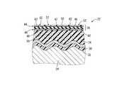
- the principal part expanded sectional view of the arm of the robot which comprises the robot cooperation apparatus shown in FIG. The disassembled perspective view of the collision detection sensor provided in the arm shown in FIG.
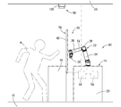
- operation of the safety device in the robot cooperation apparatus of FIG. The front view which shows the robot cooperation apparatus provided with the safety device as 2nd embodiment of this invention.
- the top view of the robot cooperation apparatus shown in FIG. The front view which shows the robot cooperation apparatus provided with the safety device as 3rd embodiment of this invention.
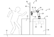
- the robot cooperation device 12 includes a robot 14 as an automatic device and a common work table 16.
- the vertical direction means the vertical direction in FIG. 2 in principle.
- the robot 14 has a structure in which an arm 22 as a moving unit is provided with respect to a support base 20 installed on a floor 18.
- the arm 22 has a multi-joint structure in which a plurality of links 24 are connected by a joint portion 26 so as to be relatively displaceable, and an end effector 28 is provided at the tip. Furthermore, the arm 22 is rotatably attached to the upper surface of the support base 20 at the base end.
- shield layers 30 are provided on the outer side of the link 24, the joint portion 26, and the end effector 28 of the arm 22, respectively.
- the shield layer 30 is provided to shield electromagnetic waves radiated from the arms 22 to the outside, and is formed to include a conductive metal such as iron, copper, or an aluminum alloy. .
- the shield layer 30 is disposed so as to cover the outer surface of the link 24 by attaching a support 32 described later to the surface of the link 24.
- the link 24 in the arm 22 is illustrated as an example, but the shield layer 30, an elastic cushion layer 34 described later, and a collision detection sensor 36 described later are also applied to the joint portion 26 and the end effector 28. Etc. are provided in the same manner as the link 24.
- the shield layer 30 of the present embodiment is, for example, a flexible resin film formed of polyethylene terephthalate (PET) or the like by a paint in which metal powder is dispersed in a base material such as rubber or synthetic resin.
- the surface is formed by a method such as silk screen printing.
- the shield layer 30 may be formed of a metal thin plate or mesh, or may be obtained by forming a coating film by directly spraying the surface of the link 24 with a paint in which metal powder is dispersed in the base material. You can also.
- the thickness of the support 32 is not particularly limited as long as the support 32 can be flexibly deformed.
- the inner surface on the link 24 side has a shape corresponding to the outer surface of the link 24 with unevenness, and the outer surface on the opposite side to the link 24 is a flat surface.
- the shield layer 30 and the support body 32 are arranged between the elastic cushion layer 34 and the link 24.
- both the shield layer 30 and the support body 32 are flexible and sufficiently thin, and are linked. Since the elastic cushion layer 34 is disposed along the outer surface of the link 24, the elastic cushion layer 34 is substantially directly superimposed on the outer surface of the link 24. 4 schematically shows the irregularities on the outer surface of the link 24, the irregularities on the outer surface of the link 24 include, for example, the control circuit and wiring arrangement of the arm 22, the design of the link housing, and the screw. It can be formed by a stop structure or the like.
- a collision detection sensor 36 constituting a collision detection means of the safety device 10 is superimposed on the outer side of the elastic cushion layer 34 in the arm 22.
- the collision detection sensor 36 of the present embodiment is a contact detection sensor that detects the contact of the operator A with the arm 22, and in this embodiment, a capacitance type planar pressure sensor is employed.
- the collision detection sensor 36 may employ various known detection type contact detection sensors. For example, an impact sensor using piezoelectric ceramics, a touch sensor such as a resistive film type, an infrared type, or a surface acoustic wave type, a contact type Any of a flow sensor, a membrane switch, and the like that detect the air flow due to deformation of the elastic layer can be employed.
- a sensor built in the robot 14 can be used as the collision detection sensor 36.
- the robot 14 includes a force sensor, a torque sensor, an encoder sensor, or the like, these sensors are used.
- the collision detection sensor 36 may be provided so as to cover substantially the entire arm 22, but may be provided so as to cover only a tip portion that can enter a dangerous area 70 described later, for example.
- the collision detection sensor 36 of the present embodiment includes a first electrode sheet 44 including a plurality of first electrodes 42 arranged in parallel on both surfaces of the dielectric layer 40, and a plurality of first electrodes 42. It has a structure in which each one of the second electrode sheet 48 provided with two electrodes 46 in parallel is superposed and fixed.
- the dielectric layer 40 is an elastically deformable sheet-like electrical insulator formed of rubber or resin elastomer, and is preferably formed of non-foamed rubber that hardly changes in volume.
- the dielectric layer 40 can be integrally formed with a first electrode sheet 44 and a second electrode sheet 48 described later.
- the first electrode sheet 44 has a structure in which a plurality of strip-like first electrodes 42 having conductivity are formed in parallel with respect to the base body 50 that is made of an electrically insulating sheet.
- the first electrode 42 is formed by mixing an elastic material such as rubber with a conductive material such as carbon filler or metal powder, and is capable of stretching and deforming.
- the first electrode 42 can be formed on the substrate 50 by screen printing or the like.
- the 1st electrode sheet 44 and the 2nd electrode sheet 48 are piled up from each one side of the thickness direction with respect to the dielectric material layer 40, and are mutually fixed by means, such as adhesion and welding.
- a collision detection sensor 36 is formed.
- the longitudinal direction of the first electrode 42 and the longitudinal direction of the second electrode 46 are different from each other.
- the first electrode 42 and the second electrode 46 cross each other through the dielectric layer 40.
- pressure detecting portions 52 for detecting the pressure acting in the facing direction based on the change in capacitance are respectively formed at the crossing facing portions of the first electrode 42 and the second electrode 46 (FIG. 4).
- the collision detection sensor 36 having a structure in which the plurality of pressure detection units 52 are arranged in a distributed manner is a capacitance type surface pressure sensor that detects the pressure acting on the surface based on a change in capacitance. ing.
- the collision detection sensor 36 having a rectangular sheet shape is shown, but the specific shape of the collision detection sensor 36 is appropriately set according to the shape of the arm 22 and the like.
- the 1st electrode 42 and the 2nd electrode 46 are not limited to strip
- a shared work table 16 is disposed next to the support table 20 that supports the robot 14.
- the shared workbench 16 is a workbench that is performed by both the robot 14 and the worker A described later.
- the shared workbench 16 is provided apart from the support table 20, but a part of the support table 20 is shared.
- the work table 16 may be used.
- a light curtain 56 that constitutes a dangerous state detection means of the safety device 10 is provided at the end of the shared work table 16 on the support table 20 side.
- the light curtain 56 which is a moving unit detecting means detects that the light beam 62 projected from the light projecting unit 58 toward the light receiving unit 60 is blocked, so that the light projecting unit 58 and the light receiving unit 60 are opposed to each other. It is possible to detect the approach of the arm 22 to the.
- the light projecting unit 58 and the light receiving unit 60 are provided at each corner of the shared work table 16 on the support table 20 side, so that the arm 22 enters the shared work table 16, in other words, the arm 22. An approach to a dangerous area 70 described later is detected by the light curtain 56.
- a plurality of light beams 62 extending in a substantially horizontal direction at a predetermined interval in the vertical direction are projected toward the light receiving unit 60, and the height of the arm 22 at what height the shared work table 16 is. It is possible to detect even if it goes up.
- a sensor control device 64 as a collision detection control device is connected to the light curtain 56.
- the sensor control device 64 switches the start and stop of detection by the collision detection sensor 36 based on the detection signal of the light curtain 56, and enables or disables the collision detection sensor 36 based on the detection signal of the light curtain 56.
- a sensor control signal is generated, and the sensor control signal is transmitted to the collision detection sensor 36. More specifically, the sensor control device 64 enables the collision detection sensor 36 based on the detection signal of the light curtain 56 that the arm 22 has been detected, while the detection signal of the light curtain 56 that has detected the arm 22 has been detected.
- the collision detection sensor 36 is invalidated based on the absence.
- the sensor control device 64 is connected to the light curtain 56 and the collision detection sensor 36 by wire or wirelessly.
- the sensor control device 64 is built in the support base 20 of the robot 14 and is connected to the light curtain 56. In addition to being connected wirelessly, it is connected to the collision detection sensor 36 by wire.
- an arm 22 is arranged on a support base 20 and a worker A is placed on the opposite side (left side in FIG. 3) across the shared work base 16 with respect to the support base 20. Is located.
- the arm 22 of the robot 14 according to the present embodiment is movable in the arm entry area 66 indicated by the alternate long and short dash line in FIG. 3, and a part of the arm entry area 66 extends on the common work table 16. .
- the arm entry area 66 of the present embodiment is set based on a pre-programmed movement range of the arm 22. For example, by setting the arm entry area 66 based on the maximum movable range of the arm 22, It is also possible to secure safety against unintended movement due to malfunction 22 or the like.
- a range in which the worker A can reach a part of the body into the common area 68 by reaching his / her hand is indicated by a one-dot chain line in FIG. 3 as the dangerous area 70 of the present embodiment.
- the dangerous area 70 In a state where the worker A is present in the danger area 70, at least a part of the worker A's body can enter the common area 68 due to a change in the posture of the worker A and the like. 22 and worker A may collide. In other words, when the worker A is located outside the dangerous area 70, the worker A does not collide with the arm 22 in the common area 68.
- the arm entry area 66, the common area 68, the dangerous area 70, and the like shown in the above embodiment are merely examples, and are appropriately set according to the work content and the work space.
- the shared area 68 is not necessarily limited to a mode set on the shared work table 16.
- the worker A is exemplified as the detection target detected by the collision detection means, but the detection target is not limited to a person, and may be an object. Further, in order to reduce the force acting upon contact with the moving part to be detected, it is desirable that a cushioning material such as the elastic cushion layer 34 is provided on the moving part, but the elastic cushion layer 34 is not essential. .
Landscapes
- Engineering & Computer Science (AREA)
- Mechanical Engineering (AREA)
- General Engineering & Computer Science (AREA)
- Robotics (AREA)
- Radar, Positioning & Navigation (AREA)
- Remote Sensing (AREA)
- Multimedia (AREA)
- Human Computer Interaction (AREA)
- Manipulator (AREA)
Abstract
La présente invention concerne un dispositif de sécurité qui présente une nouvelle structure et qui peut assurer la sécurité en cas de collisions entre une partie mobile d'un dispositif automatique et un opérateur ou autre, et qui peut améliorer l'efficacité de fonctionnement du dispositif automatique en empêchant une détection erronée. Ce dispositif de sécurité (10), qui enraie un danger provoqué par des collisions entre une partie mobile (22) d'un dispositif automatique (14) et une cible de détection A, est équipé d'un moyen de détection de collision (36) afin de détecter l'approche/le contact de la partie mobile (22) et de la cible de détection A ; un dispositif de commande de partie mobile (54) qui accélère/décélère ou qui arrête le mouvement de la partie mobile (22) sur la base d'un signal de détection provenant du moyen de détection de collision (36). La présente invention est également pourvue : d'un moyen de détection d'un état dangereux (56) dans lequel une zone de danger, où la partie mobile (22) et la cible de détection A peuvent entrer en collision, est établie, et qui détecte si la partie mobile (22) et/ou la cible de détection A est située dans la zone de danger (70) ; d'un dispositif de commande de détection de collision (64) qui valide ou réfute, sur la base du signal de détection provenant du moyen de détection d'état dangereux (56), la détection, par le moyen de détection de collision (36), de l'approche/du contact de la partie mobile (22) et de la cible de détection A.
Priority Applications (3)
| Application Number | Priority Date | Filing Date | Title |
|---|---|---|---|
| CN201880029889.2A CN110603123A (zh) | 2017-06-13 | 2018-02-15 | 安全装置 |
| EP18818924.5A EP3608068A4 (fr) | 2017-06-13 | 2018-02-15 | Dispositif de sécurité |
| US16/565,413 US20200001460A1 (en) | 2017-06-13 | 2019-09-09 | Safety device |
Applications Claiming Priority (2)
| Application Number | Priority Date | Filing Date | Title |
|---|---|---|---|
| JP2017-116252 | 2017-06-13 | ||
| JP2017116252A JP2019000930A (ja) | 2017-06-13 | 2017-06-13 | 安全装置 |
Related Child Applications (1)
| Application Number | Title | Priority Date | Filing Date |
|---|---|---|---|
| US16/565,413 Continuation US20200001460A1 (en) | 2017-06-13 | 2019-09-09 | Safety device |
Publications (1)
| Publication Number | Publication Date |
|---|---|
| WO2018230036A1 true WO2018230036A1 (fr) | 2018-12-20 |
Family
ID=64660602
Family Applications (1)
| Application Number | Title | Priority Date | Filing Date |
|---|---|---|---|
| PCT/JP2018/005198 WO2018230036A1 (fr) | 2017-06-13 | 2018-02-15 | Dispositif de sécurité |
Country Status (5)
| Country | Link |
|---|---|
| US (1) | US20200001460A1 (fr) |
| EP (1) | EP3608068A4 (fr) |
| JP (1) | JP2019000930A (fr) |
| CN (1) | CN110603123A (fr) |
| WO (1) | WO2018230036A1 (fr) |
Cited By (2)
| Publication number | Priority date | Publication date | Assignee | Title |
|---|---|---|---|---|
| EP3725183A1 (fr) * | 2019-04-18 | 2020-10-21 | Loctek Inc. | Système de commande de table élévatrice électrique et procédé de reconnaissance de résistance |
| EP3978210A4 (fr) * | 2019-05-28 | 2023-02-22 | OMRON Corporation | Système de surveillance de sécurité, dispositif de commande de surveillance de sécurité et procédé de surveillance de sécurité |
Families Citing this family (7)
| Publication number | Priority date | Publication date | Assignee | Title |
|---|---|---|---|---|
| JP6850538B2 (ja) * | 2016-02-08 | 2021-03-31 | 川崎重工業株式会社 | 作業ロボット |
| JP6922486B2 (ja) * | 2017-07-06 | 2021-08-18 | 株式会社デンソーウェーブ | ロボットの制御装置 |
| JP7243603B2 (ja) * | 2019-12-09 | 2023-03-22 | トヨタ自動車株式会社 | 搬送ロボットシステム |
| JP7421346B2 (ja) * | 2020-01-17 | 2024-01-24 | 川崎重工業株式会社 | 安全装置、自走式ロボットシステム、及び制御方法 |
| US11981517B2 (en) * | 2021-03-30 | 2024-05-14 | Dexterity, Inc. | Robotic line kitting system safety features |
| US11897706B2 (en) | 2021-03-30 | 2024-02-13 | Dexterity, Inc. | Robotic system with zone-based control |
| CN113369709A (zh) * | 2021-06-10 | 2021-09-10 | 广东宏石激光技术股份有限公司 | 一种降低交换台刹车冲击的方法及其系统 |
Citations (5)
| Publication number | Priority date | Publication date | Assignee | Title |
|---|---|---|---|---|
| JPS585208B2 (ja) | 1973-07-18 | 1983-01-29 | モンテジソン ソシエタ パ− アシオネ | 1− アザ −2− ヒドロキシベンゾアントロンノ セイゾウホウ |
| JPH05345293A (ja) * | 1992-06-15 | 1993-12-27 | Yaskawa Electric Corp | 産業用ロボットの衝突防止方法 |
| JP2010188515A (ja) * | 2009-01-26 | 2010-09-02 | Fanuc Ltd | 人間とロボットとの協調動作領域を有する生産システム |
| JP2010234495A (ja) * | 2009-03-31 | 2010-10-21 | National Institute Of Advanced Industrial Science & Technology | 安全制御装置、ロボット、システム、プログラム、及び、記録媒体 |
| WO2016103308A1 (fr) * | 2014-12-26 | 2016-06-30 | 川崎重工業株式会社 | Système de robot |
Family Cites Families (7)
| Publication number | Priority date | Publication date | Assignee | Title |
|---|---|---|---|---|
| US5280622A (en) * | 1992-07-17 | 1994-01-18 | Mitsubishi Semiconductor America, Inc. | Combined light beam and ultrasonic transducer safety sensing system |
| JP5035768B2 (ja) * | 2006-04-18 | 2012-09-26 | 独立行政法人産業技術総合研究所 | 人間ロボット共存作業用安全装置 |
| CN104428107B (zh) * | 2012-07-10 | 2016-06-29 | 西门子公司 | 机器人布置和用于控制机器人的方法 |
| DE202013105036U1 (de) * | 2013-11-08 | 2015-02-10 | Daimler Ag | Erfassungseinrichtung |
| JP6517567B2 (ja) * | 2015-03-31 | 2019-05-22 | 日本電産サンキョー株式会社 | サーボモータ制御装置及び衝突検出方法 |
| JP6678396B2 (ja) * | 2015-05-19 | 2020-04-08 | アズビル株式会社 | 衝突検知装置 |
| DE102015114463A1 (de) * | 2015-08-31 | 2017-03-02 | Kuka Systems Gmbh | Sicherheitseinrichtung und Sicherheitsverfahren |
-
2017
- 2017-06-13 JP JP2017116252A patent/JP2019000930A/ja not_active Withdrawn
-
2018
- 2018-02-15 EP EP18818924.5A patent/EP3608068A4/fr not_active Withdrawn
- 2018-02-15 WO PCT/JP2018/005198 patent/WO2018230036A1/fr unknown
- 2018-02-15 CN CN201880029889.2A patent/CN110603123A/zh not_active Withdrawn
-
2019
- 2019-09-09 US US16/565,413 patent/US20200001460A1/en not_active Abandoned
Patent Citations (5)
| Publication number | Priority date | Publication date | Assignee | Title |
|---|---|---|---|---|
| JPS585208B2 (ja) | 1973-07-18 | 1983-01-29 | モンテジソン ソシエタ パ− アシオネ | 1− アザ −2− ヒドロキシベンゾアントロンノ セイゾウホウ |
| JPH05345293A (ja) * | 1992-06-15 | 1993-12-27 | Yaskawa Electric Corp | 産業用ロボットの衝突防止方法 |
| JP2010188515A (ja) * | 2009-01-26 | 2010-09-02 | Fanuc Ltd | 人間とロボットとの協調動作領域を有する生産システム |
| JP2010234495A (ja) * | 2009-03-31 | 2010-10-21 | National Institute Of Advanced Industrial Science & Technology | 安全制御装置、ロボット、システム、プログラム、及び、記録媒体 |
| WO2016103308A1 (fr) * | 2014-12-26 | 2016-06-30 | 川崎重工業株式会社 | Système de robot |
Non-Patent Citations (1)
| Title |
|---|
| See also references of EP3608068A4 * |
Cited By (2)
| Publication number | Priority date | Publication date | Assignee | Title |
|---|---|---|---|---|
| EP3725183A1 (fr) * | 2019-04-18 | 2020-10-21 | Loctek Inc. | Système de commande de table élévatrice électrique et procédé de reconnaissance de résistance |
| EP3978210A4 (fr) * | 2019-05-28 | 2023-02-22 | OMRON Corporation | Système de surveillance de sécurité, dispositif de commande de surveillance de sécurité et procédé de surveillance de sécurité |
Also Published As
| Publication number | Publication date |
|---|---|
| US20200001460A1 (en) | 2020-01-02 |
| EP3608068A4 (fr) | 2020-07-15 |
| EP3608068A1 (fr) | 2020-02-12 |
| JP2019000930A (ja) | 2019-01-10 |
| CN110603123A (zh) | 2019-12-20 |
Similar Documents
| Publication | Publication Date | Title |
|---|---|---|
| WO2018230036A1 (fr) | Dispositif de sécurité | |
| WO2018173380A1 (fr) | Dispositif capteur | |
| JP6687573B2 (ja) | ロボットシステム | |
| JP4648486B2 (ja) | 人間とロボットとの協調動作領域を有する生産システム | |
| US20190368950A1 (en) | Sensor device | |
| JP6392910B2 (ja) | ロボットの安全確保動作機能を備えた人間協働ロボットシステム | |
| US9669548B2 (en) | Mobile collaborative robot | |
| JP6364096B2 (ja) | ロボットシステム | |
| WO2018173366A1 (fr) | Dispositif de détection | |
| JP2017030081A (ja) | 産業用ロボットシステムおよびその制御方法 | |
| JP7329902B2 (ja) | ロボット制御装置、ロボットシステム、ロボット制御方法、および、ロボット制御プログラム | |
| JP2012040626A (ja) | 人間協調ロボットシステム | |
| KR20100023722A (ko) | 자율 이동 장치 | |
| JP2018103345A (ja) | ロボットシステム | |
| CN110576455B (zh) | 多自由度影像机器人用模块化碰撞检测及保护装置 | |
| JP2022516903A (ja) | 医療撮像装置のための補充の衝突検出および防止システム | |
| CN112192617A (zh) | 多桁架传输系统的防碰撞控制方法和多桁架传输系统 | |
| CN113246831A (zh) | 作业系统 | |
| JP2005059161A (ja) | ロボット制御装置 | |
| JP2019058990A (ja) | ロボットシステム | |
| JP6448474B2 (ja) | 感圧センサおよび感圧センサを備えたロボット | |
| WO2020090342A1 (fr) | Dispositif capteur | |
| CN216464644U (zh) | 机器人控制装置 | |
| WO2021193932A1 (fr) | Capteur de capacité électrostatique, unité de capteur et robot | |
| JP2009285775A (ja) | 操作インタフェースを含む部分が操作者に対して移動可能な装置を制御するための技術 |
Legal Events
| Date | Code | Title | Description |
|---|---|---|---|
| 121 | Ep: the epo has been informed by wipo that ep was designated in this application |
Ref document number: 18818924 Country of ref document: EP Kind code of ref document: A1 |
|
| NENP | Non-entry into the national phase |
Ref country code: DE |