WO2018230036A1 - Safety device - Google Patents
Safety device Download PDFInfo
- Publication number
- WO2018230036A1 WO2018230036A1 PCT/JP2018/005198 JP2018005198W WO2018230036A1 WO 2018230036 A1 WO2018230036 A1 WO 2018230036A1 JP 2018005198 W JP2018005198 W JP 2018005198W WO 2018230036 A1 WO2018230036 A1 WO 2018230036A1
- Authority
- WO
- WIPO (PCT)
- Prior art keywords
- detection
- arm
- collision
- area
- moving part
- Prior art date
Links
Images


Classifications
-
- B—PERFORMING OPERATIONS; TRANSPORTING
- B25—HAND TOOLS; PORTABLE POWER-DRIVEN TOOLS; MANIPULATORS
- B25J—MANIPULATORS; CHAMBERS PROVIDED WITH MANIPULATION DEVICES
- B25J19/00—Accessories fitted to manipulators, e.g. for monitoring, for viewing; Safety devices combined with or specially adapted for use in connection with manipulators
- B25J19/02—Sensing devices
- B25J19/021—Optical sensing devices
- B25J19/023—Optical sensing devices including video camera means
-
- B—PERFORMING OPERATIONS; TRANSPORTING
- B25—HAND TOOLS; PORTABLE POWER-DRIVEN TOOLS; MANIPULATORS
- B25J—MANIPULATORS; CHAMBERS PROVIDED WITH MANIPULATION DEVICES
- B25J13/00—Controls for manipulators
- B25J13/08—Controls for manipulators by means of sensing devices, e.g. viewing or touching devices
- B25J13/081—Touching devices, e.g. pressure-sensitive
-
- B—PERFORMING OPERATIONS; TRANSPORTING
- B25—HAND TOOLS; PORTABLE POWER-DRIVEN TOOLS; MANIPULATORS
- B25J—MANIPULATORS; CHAMBERS PROVIDED WITH MANIPULATION DEVICES
- B25J19/00—Accessories fitted to manipulators, e.g. for monitoring, for viewing; Safety devices combined with or specially adapted for use in connection with manipulators
- B25J19/06—Safety devices
-
- B—PERFORMING OPERATIONS; TRANSPORTING
- B25—HAND TOOLS; PORTABLE POWER-DRIVEN TOOLS; MANIPULATORS
- B25J—MANIPULATORS; CHAMBERS PROVIDED WITH MANIPULATION DEVICES
- B25J9/00—Programme-controlled manipulators
- B25J9/16—Programme controls
- B25J9/1628—Programme controls characterised by the control loop
- B25J9/1651—Programme controls characterised by the control loop acceleration, rate control
-
- B—PERFORMING OPERATIONS; TRANSPORTING
- B25—HAND TOOLS; PORTABLE POWER-DRIVEN TOOLS; MANIPULATORS
- B25J—MANIPULATORS; CHAMBERS PROVIDED WITH MANIPULATION DEVICES
- B25J9/00—Programme-controlled manipulators
- B25J9/16—Programme controls
- B25J9/1674—Programme controls characterised by safety, monitoring, diagnostic
- B25J9/1676—Avoiding collision or forbidden zones
-
- F—MECHANICAL ENGINEERING; LIGHTING; HEATING; WEAPONS; BLASTING
- F16—ENGINEERING ELEMENTS AND UNITS; GENERAL MEASURES FOR PRODUCING AND MAINTAINING EFFECTIVE FUNCTIONING OF MACHINES OR INSTALLATIONS; THERMAL INSULATION IN GENERAL
- F16P—SAFETY DEVICES IN GENERAL; SAFETY DEVICES FOR PRESSES
- F16P3/00—Safety devices acting in conjunction with the control or operation of a machine; Control arrangements requiring the simultaneous use of two or more parts of the body
- F16P3/12—Safety devices acting in conjunction with the control or operation of a machine; Control arrangements requiring the simultaneous use of two or more parts of the body with means, e.g. feelers, which in case of the presence of a body part of a person in or near the danger zone influence the control or operation of the machine
- F16P3/14—Safety devices acting in conjunction with the control or operation of a machine; Control arrangements requiring the simultaneous use of two or more parts of the body with means, e.g. feelers, which in case of the presence of a body part of a person in or near the danger zone influence the control or operation of the machine the means being photocells or other devices sensitive without mechanical contact
- F16P3/141—Safety devices acting in conjunction with the control or operation of a machine; Control arrangements requiring the simultaneous use of two or more parts of the body with means, e.g. feelers, which in case of the presence of a body part of a person in or near the danger zone influence the control or operation of the machine the means being photocells or other devices sensitive without mechanical contact using sound propagation, e.g. sonar
-
- F—MECHANICAL ENGINEERING; LIGHTING; HEATING; WEAPONS; BLASTING
- F16—ENGINEERING ELEMENTS AND UNITS; GENERAL MEASURES FOR PRODUCING AND MAINTAINING EFFECTIVE FUNCTIONING OF MACHINES OR INSTALLATIONS; THERMAL INSULATION IN GENERAL
- F16P—SAFETY DEVICES IN GENERAL; SAFETY DEVICES FOR PRESSES
- F16P3/00—Safety devices acting in conjunction with the control or operation of a machine; Control arrangements requiring the simultaneous use of two or more parts of the body
- F16P3/12—Safety devices acting in conjunction with the control or operation of a machine; Control arrangements requiring the simultaneous use of two or more parts of the body with means, e.g. feelers, which in case of the presence of a body part of a person in or near the danger zone influence the control or operation of the machine
- F16P3/14—Safety devices acting in conjunction with the control or operation of a machine; Control arrangements requiring the simultaneous use of two or more parts of the body with means, e.g. feelers, which in case of the presence of a body part of a person in or near the danger zone influence the control or operation of the machine the means being photocells or other devices sensitive without mechanical contact
- F16P3/142—Safety devices acting in conjunction with the control or operation of a machine; Control arrangements requiring the simultaneous use of two or more parts of the body with means, e.g. feelers, which in case of the presence of a body part of a person in or near the danger zone influence the control or operation of the machine the means being photocells or other devices sensitive without mechanical contact using image capturing devices
-
- F—MECHANICAL ENGINEERING; LIGHTING; HEATING; WEAPONS; BLASTING
- F16—ENGINEERING ELEMENTS AND UNITS; GENERAL MEASURES FOR PRODUCING AND MAINTAINING EFFECTIVE FUNCTIONING OF MACHINES OR INSTALLATIONS; THERMAL INSULATION IN GENERAL
- F16P—SAFETY DEVICES IN GENERAL; SAFETY DEVICES FOR PRESSES
- F16P3/00—Safety devices acting in conjunction with the control or operation of a machine; Control arrangements requiring the simultaneous use of two or more parts of the body
- F16P3/12—Safety devices acting in conjunction with the control or operation of a machine; Control arrangements requiring the simultaneous use of two or more parts of the body with means, e.g. feelers, which in case of the presence of a body part of a person in or near the danger zone influence the control or operation of the machine
- F16P3/14—Safety devices acting in conjunction with the control or operation of a machine; Control arrangements requiring the simultaneous use of two or more parts of the body with means, e.g. feelers, which in case of the presence of a body part of a person in or near the danger zone influence the control or operation of the machine the means being photocells or other devices sensitive without mechanical contact
- F16P3/144—Safety devices acting in conjunction with the control or operation of a machine; Control arrangements requiring the simultaneous use of two or more parts of the body with means, e.g. feelers, which in case of the presence of a body part of a person in or near the danger zone influence the control or operation of the machine the means being photocells or other devices sensitive without mechanical contact using light grids
-
- F—MECHANICAL ENGINEERING; LIGHTING; HEATING; WEAPONS; BLASTING
- F16—ENGINEERING ELEMENTS AND UNITS; GENERAL MEASURES FOR PRODUCING AND MAINTAINING EFFECTIVE FUNCTIONING OF MACHINES OR INSTALLATIONS; THERMAL INSULATION IN GENERAL
- F16P—SAFETY DEVICES IN GENERAL; SAFETY DEVICES FOR PRESSES
- F16P3/00—Safety devices acting in conjunction with the control or operation of a machine; Control arrangements requiring the simultaneous use of two or more parts of the body
- F16P3/12—Safety devices acting in conjunction with the control or operation of a machine; Control arrangements requiring the simultaneous use of two or more parts of the body with means, e.g. feelers, which in case of the presence of a body part of a person in or near the danger zone influence the control or operation of the machine
- F16P3/14—Safety devices acting in conjunction with the control or operation of a machine; Control arrangements requiring the simultaneous use of two or more parts of the body with means, e.g. feelers, which in case of the presence of a body part of a person in or near the danger zone influence the control or operation of the machine the means being photocells or other devices sensitive without mechanical contact
- F16P3/148—Safety devices acting in conjunction with the control or operation of a machine; Control arrangements requiring the simultaneous use of two or more parts of the body with means, e.g. feelers, which in case of the presence of a body part of a person in or near the danger zone influence the control or operation of the machine the means being photocells or other devices sensitive without mechanical contact using capacitive technology
Definitions
- the present invention relates to a safety device for preventing a danger caused by a collision between an automatic device such as an industrial robot and a detection target such as an operator.
- automatic devices such as industrial robots and automatic guided vehicles (AGV) are generally used in factories and the like, for example, by promoting industrial automation.
- An automatic device is a moving part that can move in order to perform a predetermined operation, such as an arm of an industrial robot.
- Patent Document 1 discloses a safety device that can avoid a collision by controlling the operation of the gripper arm of the operating device based on the detection results of the first sensor device and the second sensor device.
- the safety device includes a first sensor device having a detection range whose distance from the operation device is small, and a second sensor device having a detection range whose distance from the operation device is larger than that of the first sensor device.
- the present invention has been made in the background of the above-mentioned circumstances, and its solution is to detect the approach or contact of an operator or the like with respect to the moving part of the automatic device to ensure safety, and to detect errors. It is an object of the present invention to provide a safety device having a novel structure capable of realizing the excellent work efficiency of an automatic device by preventing the above-described problem.
- a state detection means and a collision detection control device for enabling or disabling detection of the approach or contact between the moving part and the detection target by the collision detection means based on a detection signal of the dangerous state detection means.
- a collision detection control device for enabling or disabling detection of the approach or contact between the moving part and the detection target by the collision detection means based on a detection signal of the dangerous state detection means.
- the safety device having the structure according to the first aspect, based on the detection result of the approach or contact between the moving unit of the automatic device such as the robot and the detection target such as the worker by the collision detection unit, By controlling acceleration / deceleration and stop of the movement of the moving unit, it is possible to avoid collision between the moving unit and a detection target, reduce impact force at the time of collision, and the like. If the moving unit control device that controls acceleration / deceleration or stopping of the moving unit reduces the moving speed of the moving unit based on the detection signal of the collision detection means that detects the proximity of the moving unit and the detection target, The working efficiency can also be improved by increasing the moving speed of the moving unit when the approaching unit is separated from the detection target and the approach is not detected.
- the dangerous state detecting means includes a moving part detecting means for detecting an intrusion of the moving part with respect to the dangerous area.
- the moving part detection means it is possible to grasp whether or not the moving part of the automatic device has entered the dangerous area by the moving part detection means and whether or not the moving part is in a state of entering the dangerous area.
- the collision detection means is invalidated because a collision between the moving part and the detection target cannot occur. be able to.
- the detection target detecting means grasps whether or not the detection target such as the worker has entered the dangerous area, or whether or not the detection target is about to enter the dangerous area. If the detection target is located away from the danger area and there is no possibility of entering the detection target danger area, the collision between the moving part and the detection target cannot occur. can do.
- both the moving unit and the detection target of the automatic device can enter the dangerous area. It includes a common area, and the dangerous state detection means detects entry of both the moving unit and the detection target into the common area.
- the state in which both the moving unit and the detection target have entered the common area or the state to enter the common area is detected by the dangerous state detection unit, and based on the detection signal of the dangerous state detection unit
- the collision detection by the collision detection means can be made effective by limiting it to a more necessary state. Therefore, unnecessary deceleration and stop of the moving part due to erroneous detection of the collision detection means can be avoided more effectively, and the working efficiency of the automatic device can be improved.
- the shared area is configured by a plurality of divided areas
- the dangerous state detection means includes the moving unit and the detection target. An approach to one of the divided areas is detected.
- the shared area is divided into a plurality of divided areas, and the collision occurs only when the moving unit and the detection target are located in one divided area or when entering the one divided area.
- the detection means can be effective. Therefore, the detection by the collision detection means can be effectively limited to situations where the risk of collision is higher, and the deceleration and stop of the moving part due to erroneous detection of the collision detection means can be prevented more effectively. .
- the collision detection unit includes a contact detection sensor that detects contact of the detection target with the moving unit.
- the contact detection sensor detects a contact between the moving unit and the detection target
- the moving unit control device stops the moving unit based on a detection signal of the contact detection sensor.
- the collision detection unit includes an approach detection sensor that detects the approach of the detection target to the moving unit.
- the moving unit control device decelerates the movement of the moving unit based on the detection signal of the proximity detecting sensor when the proximity detecting sensor detects the approach between the moving unit and the detection target. It is.
- the impact force at the time of the collision between the moving unit and the detection target is further increased.
- a speed control for adjusting a moving speed of the moving unit based on a detection signal of the dangerous state detecting means is provided.
- the dangerous state detection means detects entry into at least one dangerous area of the moving part and the detection target
- the speed control device reduces the moving speed of the moving part by the speed control device, and the impact force at the time of the collision can be reduced, and the collision between the moving unit and the detection target can be more effectively prevented.
- control such as changing or stopping the moving speed of the moving unit is performed based on the detection result of the collision detection unit that detects the approach or contact between the moving unit and the detection target.
- the safety can be improved by reducing the impact force at the time of collision of the detection target or avoiding the collision.
- a dangerous state detection means for detecting that at least one of the moving part and the detection target is located in a dangerous area where there is a risk of collision is provided, and collision detection is performed based on the detection result of the dangerous state detection means. Whether the collision detection by the means is valid or invalid is switched.
- the front view of the robot cooperation apparatus shown in FIG. The top view of the robot cooperation apparatus shown in FIG.
- the principal part expanded sectional view of the arm of the robot which comprises the robot cooperation apparatus shown in FIG. The disassembled perspective view of the collision detection sensor provided in the arm shown in FIG.
- operation of the safety device in the robot cooperation apparatus of FIG. The front view which shows the robot cooperation apparatus provided with the safety device as 2nd embodiment of this invention.
- the top view of the robot cooperation apparatus shown in FIG. The front view which shows the robot cooperation apparatus provided with the safety device as 3rd embodiment of this invention.
- the robot cooperation device 12 includes a robot 14 as an automatic device and a common work table 16.
- the vertical direction means the vertical direction in FIG. 2 in principle.
- the robot 14 has a structure in which an arm 22 as a moving unit is provided with respect to a support base 20 installed on a floor 18.
- the arm 22 has a multi-joint structure in which a plurality of links 24 are connected by a joint portion 26 so as to be relatively displaceable, and an end effector 28 is provided at the tip. Furthermore, the arm 22 is rotatably attached to the upper surface of the support base 20 at the base end.
- shield layers 30 are provided on the outer side of the link 24, the joint portion 26, and the end effector 28 of the arm 22, respectively.
- the shield layer 30 is provided to shield electromagnetic waves radiated from the arms 22 to the outside, and is formed to include a conductive metal such as iron, copper, or an aluminum alloy. .
- the shield layer 30 is disposed so as to cover the outer surface of the link 24 by attaching a support 32 described later to the surface of the link 24.
- the link 24 in the arm 22 is illustrated as an example, but the shield layer 30, an elastic cushion layer 34 described later, and a collision detection sensor 36 described later are also applied to the joint portion 26 and the end effector 28. Etc. are provided in the same manner as the link 24.
- the shield layer 30 of the present embodiment is, for example, a flexible resin film formed of polyethylene terephthalate (PET) or the like by a paint in which metal powder is dispersed in a base material such as rubber or synthetic resin.
- the surface is formed by a method such as silk screen printing.
- the shield layer 30 may be formed of a metal thin plate or mesh, or may be obtained by forming a coating film by directly spraying the surface of the link 24 with a paint in which metal powder is dispersed in the base material. You can also.
- the thickness of the support 32 is not particularly limited as long as the support 32 can be flexibly deformed.
- the inner surface on the link 24 side has a shape corresponding to the outer surface of the link 24 with unevenness, and the outer surface on the opposite side to the link 24 is a flat surface.
- the shield layer 30 and the support body 32 are arranged between the elastic cushion layer 34 and the link 24.
- both the shield layer 30 and the support body 32 are flexible and sufficiently thin, and are linked. Since the elastic cushion layer 34 is disposed along the outer surface of the link 24, the elastic cushion layer 34 is substantially directly superimposed on the outer surface of the link 24. 4 schematically shows the irregularities on the outer surface of the link 24, the irregularities on the outer surface of the link 24 include, for example, the control circuit and wiring arrangement of the arm 22, the design of the link housing, and the screw. It can be formed by a stop structure or the like.
- a collision detection sensor 36 constituting a collision detection means of the safety device 10 is superimposed on the outer side of the elastic cushion layer 34 in the arm 22.
- the collision detection sensor 36 of the present embodiment is a contact detection sensor that detects the contact of the operator A with the arm 22, and in this embodiment, a capacitance type planar pressure sensor is employed.
- the collision detection sensor 36 may employ various known detection type contact detection sensors. For example, an impact sensor using piezoelectric ceramics, a touch sensor such as a resistive film type, an infrared type, or a surface acoustic wave type, a contact type Any of a flow sensor, a membrane switch, and the like that detect the air flow due to deformation of the elastic layer can be employed.
- a sensor built in the robot 14 can be used as the collision detection sensor 36.
- the robot 14 includes a force sensor, a torque sensor, an encoder sensor, or the like, these sensors are used.
- the collision detection sensor 36 may be provided so as to cover substantially the entire arm 22, but may be provided so as to cover only a tip portion that can enter a dangerous area 70 described later, for example.
- the collision detection sensor 36 of the present embodiment includes a first electrode sheet 44 including a plurality of first electrodes 42 arranged in parallel on both surfaces of the dielectric layer 40, and a plurality of first electrodes 42. It has a structure in which each one of the second electrode sheet 48 provided with two electrodes 46 in parallel is superposed and fixed.
- the dielectric layer 40 is an elastically deformable sheet-like electrical insulator formed of rubber or resin elastomer, and is preferably formed of non-foamed rubber that hardly changes in volume.
- the dielectric layer 40 can be integrally formed with a first electrode sheet 44 and a second electrode sheet 48 described later.
- the first electrode sheet 44 has a structure in which a plurality of strip-like first electrodes 42 having conductivity are formed in parallel with respect to the base body 50 that is made of an electrically insulating sheet.
- the first electrode 42 is formed by mixing an elastic material such as rubber with a conductive material such as carbon filler or metal powder, and is capable of stretching and deforming.
- the first electrode 42 can be formed on the substrate 50 by screen printing or the like.
- the 1st electrode sheet 44 and the 2nd electrode sheet 48 are piled up from each one side of the thickness direction with respect to the dielectric material layer 40, and are mutually fixed by means, such as adhesion and welding.
- a collision detection sensor 36 is formed.
- the longitudinal direction of the first electrode 42 and the longitudinal direction of the second electrode 46 are different from each other.
- the first electrode 42 and the second electrode 46 cross each other through the dielectric layer 40.
- pressure detecting portions 52 for detecting the pressure acting in the facing direction based on the change in capacitance are respectively formed at the crossing facing portions of the first electrode 42 and the second electrode 46 (FIG. 4).
- the collision detection sensor 36 having a structure in which the plurality of pressure detection units 52 are arranged in a distributed manner is a capacitance type surface pressure sensor that detects the pressure acting on the surface based on a change in capacitance. ing.
- the collision detection sensor 36 having a rectangular sheet shape is shown, but the specific shape of the collision detection sensor 36 is appropriately set according to the shape of the arm 22 and the like.
- the 1st electrode 42 and the 2nd electrode 46 are not limited to strip
- a shared work table 16 is disposed next to the support table 20 that supports the robot 14.
- the shared workbench 16 is a workbench that is performed by both the robot 14 and the worker A described later.
- the shared workbench 16 is provided apart from the support table 20, but a part of the support table 20 is shared.
- the work table 16 may be used.
- a light curtain 56 that constitutes a dangerous state detection means of the safety device 10 is provided at the end of the shared work table 16 on the support table 20 side.
- the light curtain 56 which is a moving unit detecting means detects that the light beam 62 projected from the light projecting unit 58 toward the light receiving unit 60 is blocked, so that the light projecting unit 58 and the light receiving unit 60 are opposed to each other. It is possible to detect the approach of the arm 22 to the.
- the light projecting unit 58 and the light receiving unit 60 are provided at each corner of the shared work table 16 on the support table 20 side, so that the arm 22 enters the shared work table 16, in other words, the arm 22. An approach to a dangerous area 70 described later is detected by the light curtain 56.
- a plurality of light beams 62 extending in a substantially horizontal direction at a predetermined interval in the vertical direction are projected toward the light receiving unit 60, and the height of the arm 22 at what height the shared work table 16 is. It is possible to detect even if it goes up.
- a sensor control device 64 as a collision detection control device is connected to the light curtain 56.
- the sensor control device 64 switches the start and stop of detection by the collision detection sensor 36 based on the detection signal of the light curtain 56, and enables or disables the collision detection sensor 36 based on the detection signal of the light curtain 56.
- a sensor control signal is generated, and the sensor control signal is transmitted to the collision detection sensor 36. More specifically, the sensor control device 64 enables the collision detection sensor 36 based on the detection signal of the light curtain 56 that the arm 22 has been detected, while the detection signal of the light curtain 56 that has detected the arm 22 has been detected.
- the collision detection sensor 36 is invalidated based on the absence.
- the sensor control device 64 is connected to the light curtain 56 and the collision detection sensor 36 by wire or wirelessly.
- the sensor control device 64 is built in the support base 20 of the robot 14 and is connected to the light curtain 56. In addition to being connected wirelessly, it is connected to the collision detection sensor 36 by wire.
- an arm 22 is arranged on a support base 20 and a worker A is placed on the opposite side (left side in FIG. 3) across the shared work base 16 with respect to the support base 20. Is located.
- the arm 22 of the robot 14 according to the present embodiment is movable in the arm entry area 66 indicated by the alternate long and short dash line in FIG. 3, and a part of the arm entry area 66 extends on the common work table 16. .
- the arm entry area 66 of the present embodiment is set based on a pre-programmed movement range of the arm 22. For example, by setting the arm entry area 66 based on the maximum movable range of the arm 22, It is also possible to secure safety against unintended movement due to malfunction 22 or the like.
- a range in which the worker A can reach a part of the body into the common area 68 by reaching his / her hand is indicated by a one-dot chain line in FIG. 3 as the dangerous area 70 of the present embodiment.
- the dangerous area 70 In a state where the worker A is present in the danger area 70, at least a part of the worker A's body can enter the common area 68 due to a change in the posture of the worker A and the like. 22 and worker A may collide. In other words, when the worker A is located outside the dangerous area 70, the worker A does not collide with the arm 22 in the common area 68.
- the arm entry area 66, the common area 68, the dangerous area 70, and the like shown in the above embodiment are merely examples, and are appropriately set according to the work content and the work space.
- the shared area 68 is not necessarily limited to a mode set on the shared work table 16.
- the worker A is exemplified as the detection target detected by the collision detection means, but the detection target is not limited to a person, and may be an object. Further, in order to reduce the force acting upon contact with the moving part to be detected, it is desirable that a cushioning material such as the elastic cushion layer 34 is provided on the moving part, but the elastic cushion layer 34 is not essential. .
Abstract
The present invention provides a safety device which has a novel structure and which can ensure safety against collisions between a moving part of an automatic device and an operator or the like, and improve the operation efficiency of the automatic device by preventing erroneous detection. This safety device 10, which prevents danger caused by collisions between a moving part 22 of an automatic device 14 and a detection target A, is provided with a collision detection means 36 for detecting the approach/contact of the moving part 22 and the detection target A; and a moving part control device 54 which accelerates/decelerates or stops the movement of the moving part 22 on the basis of a detection signal from the collision detection means 36. The present invention is also provided with: a dangerous state detection means 56 in which a danger region 70, where the moving part 22 and the detection target A can collide, is set, and which detects whether at least one among the moving part 22 and the detection target A is located in the danger region 70; and a collision detection control device 64 which validates or invalidates, on the basis of the detection signal from the dangerous state detection means 56, the detection, by the collision detection means 36, of the approach/contact of the moving part 22 and the detection target A.
Description
本発明は、産業用ロボットなどの自動装置と作業者などの検出対象との衝突による危険を防止する安全装置に関するものである。
The present invention relates to a safety device for preventing a danger caused by a collision between an automatic device such as an industrial robot and a detection target such as an operator.
従来から、例えば産業の自動化の推進によって、工場などでは産業用ロボットや無人搬送車(AGV)などの自動装置が一般的に用いられている。このような自動装置は、産業用ロボットのアームなどのように、全体乃至は一部が所定の作業を実行するために移動可能な移動部とされている。
Conventionally, automatic devices such as industrial robots and automatic guided vehicles (AGV) are generally used in factories and the like, for example, by promoting industrial automation. Such an automatic device is a moving part that can move in order to perform a predetermined operation, such as an arm of an industrial robot.
ところで、人間の作業者と同じ空間で作業を行う協働ロボットなどの自動装置の採用が増えるに従って、自動装置の移動部と作業者の衝突を安全柵に代わる手段で防いで、安全性の向上を図ることが必要となってきている。例えば、産業用ロボットと作業者が同じ空間で作業を行う場合には、産業用ロボットのアームなどが動く際に、アームなどが作業者自身や作業者が使う工具などの他部材と衝突することによる事故の発生を防止し、接触時に作業者の負傷やアームなどの物の損傷を回避できることが重要である。
By the way, as the adoption of automatic devices such as collaborative robots that perform work in the same space as human workers increases, safety is improved by preventing the moving parts of the automatic devices and workers from colliding with means instead of safety fences. It is necessary to plan. For example, when an industrial robot and an operator work in the same space, when the arm of the industrial robot moves, the arm collides with the worker himself or other members such as tools used by the operator. It is important to prevent accidents caused by accidents and to avoid injury of workers and damage to objects such as arms during contact.
そこで、特許第5805208号公報(特許文献1)には、操作装置のグリッパアームの動作を第1センサ装置と第2センサ装置の検出結果に基づいて制御することで、衝突を回避し得る安全装置が提案されている。この安全装置は、操作装置からの距離が小さい検出範囲を有する第1センサ装置と、第1センサ装置よりも操作装置からの距離が大きい検出範囲を有する第2センサ装置とを備えており、第2センサ装置が反応した場合に操作装置の速度を通常よりも低減させると共に、第1センサ装置が反応した場合には、操作装置の動作を停止させることにより、操作装置と作業者などとの接触を防止する。
Therefore, Japanese Patent No. 5805208 (Patent Document 1) discloses a safety device that can avoid a collision by controlling the operation of the gripper arm of the operating device based on the detection results of the first sensor device and the second sensor device. Has been proposed. The safety device includes a first sensor device having a detection range whose distance from the operation device is small, and a second sensor device having a detection range whose distance from the operation device is larger than that of the first sensor device. When the two-sensor device reacts, the speed of the operating device is reduced than usual, and when the first sensor device reacts, the operation device is stopped so that the operation device contacts the operator. To prevent.
しかしながら、特許文献1の安全装置では、操作装置のグリッパアームと作業者が相互に衝突し得ない位置にいる場合にも、第1センサ装置と第2センサ装置による検出が継続的に実行されることから、第1センサ装置と第2センサ装置の誤検出による操作装置の減速や停止が発生することで、作業効率が低下するおそれがあった。特に操作装置に設けられた第1センサ装置は、操作装置の駆動による振動などが入力されることから、誤検出による操作装置の不必要な停止が比較的に問題になり易い。
However, in the safety device disclosed in Patent Document 1, detection by the first sensor device and the second sensor device is continuously performed even when the gripper arm of the operating device and the operator are in a position where they cannot collide with each other. For this reason, there is a possibility that the working efficiency may be reduced due to the occurrence of deceleration or stop of the operating device due to erroneous detection of the first sensor device and the second sensor device. In particular, the first sensor device provided in the operating device receives vibrations due to the driving of the operating device, etc., so unnecessary stoppage of the operating device due to erroneous detection is relatively problematic.
本発明は、上述の事情を背景に為されたものであって、その解決課題は、自動装置の移動部に対する作業者などの接近乃至は接触を検出して安全性を確保できると共に、誤検出の防止によって自動装置の優れた作業効率も実現できる、新規な構造の安全装置を提供することにある。
The present invention has been made in the background of the above-mentioned circumstances, and its solution is to detect the approach or contact of an operator or the like with respect to the moving part of the automatic device to ensure safety, and to detect errors. It is an object of the present invention to provide a safety device having a novel structure capable of realizing the excellent work efficiency of an automatic device by preventing the above-described problem.
以下、このような課題を解決するために為された本発明の態様を記載する。なお、以下に記載の各態様において採用される構成要素は、可能な限り任意の組み合わせで採用可能である。
Hereinafter, embodiments of the present invention made to solve such problems will be described. In addition, the component employ | adopted in each aspect as described below is employable by arbitrary combinations as much as possible.
すなわち、本発明の第一の態様は、自動装置に設けられた移動部と移動可能な検出対象との衝突による危険を防止する安全装置であって、前記自動装置の前記移動部には前記検出対象の接近乃至は接触を検出する衝突検出手段が設けられていると共に、該衝突検出手段の検出信号に基づいて該移動部の移動を加減速又は停止する移動部制御装置が設けられている一方、該自動装置の該移動部と該検出対象とが衝突し得る危険領域が設定されていると共に、該移動部と該検出対象の少なくとも一方が該危険領域に位置するか否かを検出する危険状態検出手段が設けられており、該衝突検出手段による該移動部と該検出対象の接近乃至は接触の検出を該危険状態検出手段の検出信号に基づいて有効又は無効とする衝突検出制御装置が設けられていることを、特徴とする。
That is, the first aspect of the present invention is a safety device that prevents a danger caused by a collision between a moving unit provided in an automatic device and a movable detection target, and the detection unit includes the detection unit in the moving unit of the automatic device. While a collision detection means for detecting approach or contact of an object is provided, a moving part control device for accelerating / decelerating or stopping the movement of the moving part based on a detection signal of the collision detecting means is provided. A danger area in which the moving part of the automatic device and the detection target can collide is set, and a risk of detecting whether at least one of the moving part and the detection target is located in the dangerous area. There is provided a state detection means, and a collision detection control device for enabling or disabling detection of the approach or contact between the moving part and the detection target by the collision detection means based on a detection signal of the dangerous state detection means. Provided The Rukoto, and features.
このような第一の態様に従う構造とされた安全装置によれば、衝突検出手段によるロボットなどの自動装置の移動部と作業者などの検出対象との接近乃至は接触の検出結果に基づいて、移動部の移動の加減速や停止を制御することにより、それら移動部と検出対象の衝突の回避や衝突時の衝撃力の低減などが図られる。なお、移動部の加減速又は停止を制御する移動部制御装置が、移動部と検出対象の接近を検出した衝突検出手段の検出信号に基づいて移動部の移動速度を低減する場合には、移動部と検出対象が離れて接近が検出されなくなった場合に移動部の移動速度を増すことで、作業効率の向上を図ることもできる。
According to the safety device having the structure according to the first aspect, based on the detection result of the approach or contact between the moving unit of the automatic device such as the robot and the detection target such as the worker by the collision detection unit, By controlling acceleration / deceleration and stop of the movement of the moving unit, it is possible to avoid collision between the moving unit and a detection target, reduce impact force at the time of collision, and the like. If the moving unit control device that controls acceleration / deceleration or stopping of the moving unit reduces the moving speed of the moving unit based on the detection signal of the collision detection means that detects the proximity of the moving unit and the detection target, The working efficiency can also be improved by increasing the moving speed of the moving unit when the approaching unit is separated from the detection target and the approach is not detected.
さらに、衝突検出手段による衝突の検出は、移動部と検出対象の少なくとも一方が衝突の危険性がある危険領域に位置した状態において有効とされるようになっており、移動部と検出対象の両方が危険領域外に位置して衝突の危険性がない状態では、衝突検出手段による衝突の検出が無効とされる。これにより、衝突検出手段の誤検出に起因する移動部の不必要な減速や停止が生じ難くなって、自動装置による作業の効率向上などが図られる。
Furthermore, the collision detection by the collision detection means is effective when at least one of the moving unit and the detection target is located in a dangerous area where there is a risk of collision. In the state where there is no danger of collision because it is located outside the danger area, the collision detection by the collision detection means is invalidated. As a result, unnecessary deceleration and stop of the moving part due to erroneous detection of the collision detection means are less likely to occur, and the efficiency of work by the automatic device is improved.
本発明の第二の態様は、第一の態様に記載された安全装置において、前記危険状態検出手段が前記危険領域に対する前記移動部の進入を検出する移動部検出手段を含んでいるものである。
According to a second aspect of the present invention, in the safety device described in the first aspect, the dangerous state detecting means includes a moving part detecting means for detecting an intrusion of the moving part with respect to the dangerous area. .
第二の態様によれば、移動部検出手段によって自動装置の移動部が危険領域に進入した状態であるか否かや、危険領域に進入しようとしている状態であるか否かを把握することができて、移動部が危険領域から離れて位置して移動部の危険領域への進入の可能性がない状態では、移動部と検出対象の衝突が生じ得ないことから衝突検出手段を無効にすることができる。
According to the second aspect, it is possible to grasp whether or not the moving part of the automatic device has entered the dangerous area by the moving part detection means and whether or not the moving part is in a state of entering the dangerous area. In a state where the moving part is located away from the dangerous area and there is no possibility of the moving part entering the dangerous area, the collision detection means is invalidated because a collision between the moving part and the detection target cannot occur. be able to.
本発明の第三の態様は、第一又は第二の態様に記載された安全装置において、前記危険状態検出手段が前記危険領域に対する前記検出対象の進入を検出する検出対象検出手段を含んでいるものである。
According to a third aspect of the present invention, in the safety device described in the first or second aspect, the dangerous state detection means includes detection target detection means for detecting the detection target entering the dangerous area. Is.
第三の態様によれば、検出対象検出手段によって作業者などの検出対象が危険領域に進入した状態であるか否かや、危険領域に進入しようとしている状態であるか否かを把握することができて、検出対象が危険領域から離れて位置して検出対象の危険領域への進入の可能性がない状態では、移動部と検出対象の衝突が生じ得ないことから衝突検出手段を無効にすることができる。
According to the third aspect, the detection target detecting means grasps whether or not the detection target such as the worker has entered the dangerous area, or whether or not the detection target is about to enter the dangerous area. If the detection target is located away from the danger area and there is no possibility of entering the detection target danger area, the collision between the moving part and the detection target cannot occur. can do.
本発明の第四の態様は、第一~第三の何れか1つの態様に記載された安全装置において、前記危険領域は前記自動装置の前記移動部と前記検出対象との両方が進入可能な共用領域を含んでおり、前記危険状態検出手段は該移動部と該検出対象の両方の該共用領域に対する進入を検出するものである。
According to a fourth aspect of the present invention, in the safety device according to any one of the first to third aspects, both the moving unit and the detection target of the automatic device can enter the dangerous area. It includes a common area, and the dangerous state detection means detects entry of both the moving unit and the detection target into the common area.
第四の態様によれば、移動部と検出対象の両方が共用領域に進入した状態や共用領域に進入しようとする状態を危険状態検出手段によって検出して、危険状態検出手段の検出信号に基づいて衝突検出手段の有効と無効を切り替えることにより、衝突検出手段による衝突の検出をより必要性の高い状態に限定して有効とすることができる。従って、衝突検出手段の誤検出による移動部の不必要な減速や停止がより効果的に回避されて、自動装置の作業効率の向上が図られる。
According to the fourth aspect, the state in which both the moving unit and the detection target have entered the common area or the state to enter the common area is detected by the dangerous state detection unit, and based on the detection signal of the dangerous state detection unit By switching between valid and invalid of the collision detection means, the collision detection by the collision detection means can be made effective by limiting it to a more necessary state. Therefore, unnecessary deceleration and stop of the moving part due to erroneous detection of the collision detection means can be avoided more effectively, and the working efficiency of the automatic device can be improved.
本発明の第五の態様は、第四の態様に記載された安全装置において、前記共用領域が複数の区分領域によって構成されていると共に、前記危険状態検出手段は該移動部と該検出対象の一つの該区分領域に対する進入を検出するものである。
According to a fifth aspect of the present invention, in the safety device according to the fourth aspect, the shared area is configured by a plurality of divided areas, and the dangerous state detection means includes the moving unit and the detection target. An approach to one of the divided areas is detected.
第五の態様によれば、共用領域を複数の区分領域に区分けして、移動部と検出対象が一つの区分領域に位置している場合或いは一つの区分領域に進入しようとしている場合にのみ衝突検出手段を有効とすることができる。従って、衝突検出手段による検出をより衝突の危険性が高い状況に限定して有効とすることができて、衝突検出手段の誤検出による移動部の減速や停止を一層効果的に防ぐことができる。
According to the fifth aspect, the shared area is divided into a plurality of divided areas, and the collision occurs only when the moving unit and the detection target are located in one divided area or when entering the one divided area. The detection means can be effective. Therefore, the detection by the collision detection means can be effectively limited to situations where the risk of collision is higher, and the deceleration and stop of the moving part due to erroneous detection of the collision detection means can be prevented more effectively. .
本発明の第六の態様は、第一~第五の何れか1つの態様に記載された安全装置において、前記衝突検出手段が前記検出対象の前記移動部に対する接触を検出する接触検出センサを有しており、該接触検出センサがそれら移動部と検出対象の接触を検出した場合に該接触検出センサの検出信号に基づいて前記移動部制御装置が該移動部を停止するようにしたものである。
According to a sixth aspect of the present invention, in the safety device according to any one of the first to fifth aspects, the collision detection unit includes a contact detection sensor that detects contact of the detection target with the moving unit. When the contact detection sensor detects a contact between the moving unit and the detection target, the moving unit control device stops the moving unit based on a detection signal of the contact detection sensor. .
第六の態様によれば、検出対象の移動部に対する接触を検出した場合に移動部を停止させることによって、移動部と検出対象の衝突時に作用する衝撃力を低減することができる。しかも、接触時に作用する圧力などを接触検出センサによって検出することで、誤検出の頻度を比較的に少なくすることができる。
According to the sixth aspect, it is possible to reduce the impact force that acts when the moving unit and the detection target collide by stopping the moving unit when contact with the moving unit to be detected is detected. In addition, the frequency of erroneous detection can be relatively reduced by detecting the pressure acting at the time of contact by the contact detection sensor.
本発明の第七の態様は、第一~第六の何れか1つの態様に記載された安全装置において、前記衝突検出手段が前記検出対象の前記移動部に対する接近を検出する接近検出センサを有しており、該接近検出センサがそれら移動部と検出対象の接近を検出した場合に該接近検出センサの検出信号に基づいて前記移動部制御装置が該移動部の移動を減速するようにしたものである。
According to a seventh aspect of the present invention, in the safety device according to any one of the first to sixth aspects, the collision detection unit includes an approach detection sensor that detects the approach of the detection target to the moving unit. The moving unit control device decelerates the movement of the moving unit based on the detection signal of the proximity detecting sensor when the proximity detecting sensor detects the approach between the moving unit and the detection target. It is.
第七の態様によれば、移動部と検出対象が接触する前の接近状態において移動部の移動速度を低減乃至は移動を停止することにより、移動部と検出対象の衝突時の衝撃力をより効果的に低減することができると共に、移動部と検出対象の衝突を未然に防ぐことも可能となる。
According to the seventh aspect, by reducing or stopping the movement speed of the moving unit in the approaching state before the moving unit and the detection target come into contact, the impact force at the time of the collision between the moving unit and the detection target is further increased. In addition to being able to reduce effectively, it is also possible to prevent a collision between the moving unit and the detection target.
本発明の第八の態様は、第一~第七の何れか1つの態様に記載された安全装置において、前記移動部の移動速度を前記危険状態検出手段の検出信号に基づいて調節する速度制御装置が設けられているものである。
According to an eighth aspect of the present invention, in the safety device according to any one of the first to seventh aspects, a speed control for adjusting a moving speed of the moving unit based on a detection signal of the dangerous state detecting means. A device is provided.
第八の態様によれば、例えば、危険状態検出手段が移動部と検出対象の少なくとも一方の危険領域への進入を検出した場合に、速度制御装置によって移動部の移動速度を低減することにより、衝突時の衝撃力の低減を図ることができると共に、移動部と検出対象の衝突をより効果的に未然に防ぐことも可能となる。
According to the eighth aspect, for example, when the dangerous state detection means detects entry into at least one dangerous area of the moving part and the detection target, by reducing the moving speed of the moving part by the speed control device, The impact force at the time of the collision can be reduced, and the collision between the moving unit and the detection target can be more effectively prevented.
本発明によれば、移動部と検出対象との接近乃至は接触を検出する衝突検出手段の検出結果に基づいて、移動部の移動速度の変更や停止といった制御がなされることから、移動部と検出対象の衝突時の衝撃力の低減や衝突の回避などによって安全性の向上が図られる。更に、移動部と検出対象の少なくとも一方が衝突の危険性がある危険領域に位置していることを検出する危険状態検出手段が設けられており、危険状態検出手段の検出結果に基づいて衝突検出手段による衝突の検出の有効と無効が切り替えられる。従って、移動部と検出対象の衝突の危険性がある状態では、衝突検出手段による安全性の確保が図られると共に、移動部と検出対象の衝突の危険性がない状態では、衝突検出手段の誤検出による移動部の不必要な停止が防止されて、自動装置の作業効率の向上が図られる。
According to the present invention, control such as changing or stopping the moving speed of the moving unit is performed based on the detection result of the collision detection unit that detects the approach or contact between the moving unit and the detection target. The safety can be improved by reducing the impact force at the time of collision of the detection target or avoiding the collision. Furthermore, a dangerous state detection means for detecting that at least one of the moving part and the detection target is located in a dangerous area where there is a risk of collision is provided, and collision detection is performed based on the detection result of the dangerous state detection means. Whether the collision detection by the means is valid or invalid is switched. Therefore, in a state where there is a risk of collision between the moving unit and the detection target, safety is ensured by the collision detection unit, and in a state where there is no risk of collision between the moving unit and the detection target, an error of the collision detection unit occurs. Unnecessary stopping of the moving part due to detection is prevented, and the working efficiency of the automatic apparatus is improved.
以下、本発明の実施形態について、図面を参照しつつ説明する。
Hereinafter, embodiments of the present invention will be described with reference to the drawings.
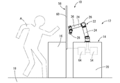
図1~3には、本発明の第一の実施形態としての安全装置10を備えたロボット協働装置12が示されている。ロボット協働装置12は、自動装置としてのロボット14と共用作業台16を備えている。なお、以下の説明において、上下方向とは、原則として、図2中の上下方向を言う。
1 to 3 show a robot cooperating apparatus 12 having a safety device 10 as a first embodiment of the present invention. The robot cooperation device 12 includes a robot 14 as an automatic device and a common work table 16. In the following description, the vertical direction means the vertical direction in FIG. 2 in principle.
ロボット14は、床18に設置された支持台20に対して、移動部としてのアーム22が設けられた構造を有している。アーム22は、複数のリンク24を関節部26によって相対変位可能に連結した多関節構造を有しており、先端にエンドエフェクタ28が設けられている。更に、アーム22は、基端が支持台20の上面に回転可能に取り付けられている。
The robot 14 has a structure in which an arm 22 as a moving unit is provided with respect to a support base 20 installed on a floor 18. The arm 22 has a multi-joint structure in which a plurality of links 24 are connected by a joint portion 26 so as to be relatively displaceable, and an end effector 28 is provided at the tip. Furthermore, the arm 22 is rotatably attached to the upper surface of the support base 20 at the base end.
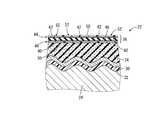
また、アーム22のリンク24や関節部26、エンドエフェクタ28の外側には、それぞれシールド層30が設けられている。シールド層30は、図4に示すように、アーム22から外側へ放射される電磁波などを遮るために設けられており、例えば鉄や銅、アルミニウム合金などの導電性金属を含んで形成されている。そして、シールド層30は、後述する支持体32をリンク24の表面に貼り付けることにより、リンク24の外面を覆うように配されている。なお、図4では、アーム22におけるリンク24が例として図示されているが、関節部26やエンドエフェクタ28に対しても、シールド層30や後述する弾性クッション層34、同じく後述する衝突検出センサ36などがリンク24と同様に設けられる。
Further, shield layers 30 are provided on the outer side of the link 24, the joint portion 26, and the end effector 28 of the arm 22, respectively. As shown in FIG. 4, the shield layer 30 is provided to shield electromagnetic waves radiated from the arms 22 to the outside, and is formed to include a conductive metal such as iron, copper, or an aluminum alloy. . The shield layer 30 is disposed so as to cover the outer surface of the link 24 by attaching a support 32 described later to the surface of the link 24. In FIG. 4, the link 24 in the arm 22 is illustrated as an example, but the shield layer 30, an elastic cushion layer 34 described later, and a collision detection sensor 36 described later are also applied to the joint portion 26 and the end effector 28. Etc. are provided in the same manner as the link 24.
本実施形態のシールド層30は、例えば、金属粉末をゴムや合成樹脂などの基材に分散させてなる塗料によって、ポリエチレンテレフタレート(PET)などで形成された柔軟な樹脂フィルムである支持体32の表面に対して、シルクスクリーン印刷などの方法で形成されている。更に、シールド層30は、金属の薄板やメッシュで形成しても良いし、金属粉末を基材に分散させた塗料をリンク24の表面に直接吹き付けるなどして塗膜を形成することで得ることもできる。また、支持体32の厚さは、支持体32が柔軟に変形可能とされていれば、特に限定されるものではない。
The shield layer 30 of the present embodiment is, for example, a flexible resin film formed of polyethylene terephthalate (PET) or the like by a paint in which metal powder is dispersed in a base material such as rubber or synthetic resin. The surface is formed by a method such as silk screen printing. Further, the shield layer 30 may be formed of a metal thin plate or mesh, or may be obtained by forming a coating film by directly spraying the surface of the link 24 with a paint in which metal powder is dispersed in the base material. You can also. The thickness of the support 32 is not particularly limited as long as the support 32 can be flexibly deformed.
また、シールド層30の外側には、弾性クッション層34が設けられている。弾性クッション層34は、ゴムや樹脂エラストマなどで形成されており、好適には、連続気泡又は独立気泡の発泡体、或いはそれら連続気泡と独立気泡の混在した発泡体とされている。弾性クッション層34の形成材料は、特に限定されないが、例えば、半硬質の発泡ウレタンなどが好適に採用され得る。尤も、弾性クッション層34は、非発泡のゴムや樹脂エラストマで形成されていても良い。
Further, an elastic cushion layer 34 is provided outside the shield layer 30. The elastic cushion layer 34 is formed of rubber, resin elastomer, or the like, and is preferably an open cell or closed cell foam, or a foam in which these open cells and closed cells are mixed. Although the material for forming the elastic cushion layer 34 is not particularly limited, for example, semi-rigid urethane foam or the like can be suitably employed. However, the elastic cushion layer 34 may be formed of non-foamed rubber or resin elastomer.
本実施形態の弾性クッション層34は、リンク24側となる内面が、凹凸のあるリンク24の外面に対応する形状とされていると共に、リンク24と反対側となる外面が平面とされている。なお、本実施形態では、シールド層30および支持体32が弾性クッション層34とリンク24の間に配されているが、シールド層30および支持体32は何れも柔軟且つ十分に薄肉とされてリンク24の外面に沿って配されることから、弾性クッション層34は実質的にリンク24の外面に対して直接的に重ね合わされている。また、図4では、リンク24の外面の凹凸が概略的に図示されているが、リンク24の外面の凹凸は、例えば、アーム22の制御回路や配線の配設、リンク筐体のデザインやねじ止め構造などによって形成され得る。
In the elastic cushion layer 34 of the present embodiment, the inner surface on the link 24 side has a shape corresponding to the outer surface of the link 24 with unevenness, and the outer surface on the opposite side to the link 24 is a flat surface. In this embodiment, the shield layer 30 and the support body 32 are arranged between the elastic cushion layer 34 and the link 24. However, both the shield layer 30 and the support body 32 are flexible and sufficiently thin, and are linked. Since the elastic cushion layer 34 is disposed along the outer surface of the link 24, the elastic cushion layer 34 is substantially directly superimposed on the outer surface of the link 24. 4 schematically shows the irregularities on the outer surface of the link 24, the irregularities on the outer surface of the link 24 include, for example, the control circuit and wiring arrangement of the arm 22, the design of the link housing, and the screw. It can be formed by a stop structure or the like.
さらに、アーム22における弾性クッション層34の外側には、安全装置10の衝突検出手段を構成する衝突検出センサ36が重ね合わされている。本実施形態の衝突検出センサ36は、アーム22に対する作業者Aの接触を検出する接触検出センサであって、本実施形態では静電容量型の面状感圧センサが採用されている。尤も、衝突検出センサ36は、各種公知の検出方式の接触検出センサを採用可能であり、例えば、圧電セラミックスを用いた衝撃センサ、抵抗膜方式や赤外線方式や表面弾性波方式などのタッチセンサ、接触時の弾性層の変形による空気の流れを検出する流量センサ、メンブレンスイッチなどをいずれも採用できる。更に、衝突検出センサ36としてロボット14に内蔵されるセンサを利用することも可能であり、例えば、ロボット14に力覚センサやトルクセンサ、エンコーダセンサなどが内蔵されている場合には、それらのセンサを衝突検出センサ36として利用することもできる。なお、衝突検出センサ36は、アーム22の略全体を覆うように設けられていても良いが、例えば、後述する危険領域70に進入し得る先端部分のみを覆うように設けられていても良い。
Further, a collision detection sensor 36 constituting a collision detection means of the safety device 10 is superimposed on the outer side of the elastic cushion layer 34 in the arm 22. The collision detection sensor 36 of the present embodiment is a contact detection sensor that detects the contact of the operator A with the arm 22, and in this embodiment, a capacitance type planar pressure sensor is employed. However, the collision detection sensor 36 may employ various known detection type contact detection sensors. For example, an impact sensor using piezoelectric ceramics, a touch sensor such as a resistive film type, an infrared type, or a surface acoustic wave type, a contact type Any of a flow sensor, a membrane switch, and the like that detect the air flow due to deformation of the elastic layer can be employed. Furthermore, a sensor built in the robot 14 can be used as the collision detection sensor 36. For example, when the robot 14 includes a force sensor, a torque sensor, an encoder sensor, or the like, these sensors are used. Can also be used as the collision detection sensor 36. The collision detection sensor 36 may be provided so as to cover substantially the entire arm 22, but may be provided so as to cover only a tip portion that can enter a dangerous area 70 described later, for example.
本実施形態の衝突検出センサ36は、図5に示すように、誘電体層40の両面に対して、複数の第一の電極42を並列的に備える第一の電極シート44と、複数の第二の電極46を並列的に備える第二の電極シート48との各一方を重ね合わせて固着した構造を有している。
As shown in FIG. 5, the collision detection sensor 36 of the present embodiment includes a first electrode sheet 44 including a plurality of first electrodes 42 arranged in parallel on both surfaces of the dielectric layer 40, and a plurality of first electrodes 42. It has a structure in which each one of the second electrode sheet 48 provided with two electrodes 46 in parallel is superposed and fixed.
誘電体層40は、ゴムや樹脂エラストマで形成された弾性変形可能なシート状の電気絶縁体であって、好適には、体積変化が殆ど生じない非発泡のゴムで形成されている。なお、誘電体層40は、後述する第一の電極シート44および第二の電極シート48に一体形成され得る。
The dielectric layer 40 is an elastically deformable sheet-like electrical insulator formed of rubber or resin elastomer, and is preferably formed of non-foamed rubber that hardly changes in volume. The dielectric layer 40 can be integrally formed with a first electrode sheet 44 and a second electrode sheet 48 described later.
第一の電極シート44は、電気絶縁性でシート状とされた基体50に対して、導電性を有する帯状の第一の電極42の複数が並列的に形成された構造を有している。第一の電極42は、ゴムなどの弾性材料にカーボンフィラーや金属粉などの導電材料を混合して形成されており、伸縮変形可能とされている。なお、第一の電極42は、基体50に対して、スクリーン印刷などによって形成され得る。
The first electrode sheet 44 has a structure in which a plurality of strip-like first electrodes 42 having conductivity are formed in parallel with respect to the base body 50 that is made of an electrically insulating sheet. The first electrode 42 is formed by mixing an elastic material such as rubber with a conductive material such as carbon filler or metal powder, and is capable of stretching and deforming. The first electrode 42 can be formed on the substrate 50 by screen printing or the like.
第二の電極シート48は、第一の電極シート44と同様に、電気絶縁性でシート状とされた基体50に対して、導電性で伸縮変形可能な帯状の第二の電極46が並列的に複数形成された構造を有している。第二の電極46の形成材料や基体50への形成方法などは、第一の電極42と同様である。
Similarly to the first electrode sheet 44, the second electrode sheet 48 has a strip-like second electrode 46 that is electrically conductive and stretchable and deformable in parallel with the base body 50 that is electrically insulating and sheet-like. A plurality of structures are formed. The material for forming the second electrode 46 and the method for forming it on the substrate 50 are the same as those for the first electrode 42.
そして、第一の電極シート44と第二の電極シート48が、誘電体層40に対して厚さ方向の各一方側から重ね合わされて、接着や溶着などの手段によって相互に固着されることにより、衝突検出センサ36が形成されている。かかる誘電体層40と第一,第二の電極シート44,48の重ね合わせ状態において、第一の電極42の長手方向と第二の電極46の長手方向が互いに異なる方向とされており、それら第一の電極42と第二の電極46が誘電体層40を介して相互に交差対向している。これにより、第一の電極42と第二の電極46の交差対向部分には、対向方向に作用する圧力を静電容量の変化に基づいて検出する圧力検出部52がそれぞれ形成されている(図4参照)。従って、複数の圧力検出部52が分散して配置された構造を有する衝突検出センサ36は、面に作用する圧力を静電容量の変化に基づいて検出する静電容量型の面圧センサとされている。なお、図5では、矩形シート状の衝突検出センサ36が示されているが、衝突検出センサ36の具体的な形状は、アーム22の形状などに応じて適宜に設定される。
And the 1st electrode sheet 44 and the 2nd electrode sheet 48 are piled up from each one side of the thickness direction with respect to the dielectric material layer 40, and are mutually fixed by means, such as adhesion and welding. A collision detection sensor 36 is formed. In the overlapping state of the dielectric layer 40 and the first and second electrode sheets 44 and 48, the longitudinal direction of the first electrode 42 and the longitudinal direction of the second electrode 46 are different from each other. The first electrode 42 and the second electrode 46 cross each other through the dielectric layer 40. As a result, pressure detecting portions 52 for detecting the pressure acting in the facing direction based on the change in capacitance are respectively formed at the crossing facing portions of the first electrode 42 and the second electrode 46 (FIG. 4). Accordingly, the collision detection sensor 36 having a structure in which the plurality of pressure detection units 52 are arranged in a distributed manner is a capacitance type surface pressure sensor that detects the pressure acting on the surface based on a change in capacitance. ing. In FIG. 5, the collision detection sensor 36 having a rectangular sheet shape is shown, but the specific shape of the collision detection sensor 36 is appropriately set according to the shape of the arm 22 and the like.
そして、各複数の第一の電極42と第二の電極46に対して所定の検出用電流が走査的に流されることにより、各圧力検出部52の静電容量が検出されるようになっている。なお、第一の電極42と第二の電極46は、帯状に限定されず、例えばそれぞれ独立した複数のスポット状とされて、各別に対向するように配置されていても良い。
Then, a predetermined detection current is caused to flow through each of the plurality of first electrodes 42 and the second electrodes 46, whereby the capacitance of each pressure detection unit 52 is detected. Yes. In addition, the 1st electrode 42 and the 2nd electrode 46 are not limited to strip | belt shape, For example, it is set as the some independent spot shape, for example, and may be arrange | positioned so that it may mutually oppose.
また、衝突検出センサ36には、移動部制御装置としてのアーム制御装置54が接続されている。アーム制御装置54は、衝突検出センサ36による衝突検出信号に基づいてアーム22の減速や緊急停止などを実行するものであって、本実施形態では、図2に示すようにロボット14の支持台20に内蔵されている。なお、アーム制御装置54は、衝突検出センサ36に対して有線で接続されていても良いし、無線で接続されていても良い。
Further, an arm control device 54 as a moving unit control device is connected to the collision detection sensor 36. The arm control device 54 executes deceleration or emergency stop of the arm 22 based on the collision detection signal from the collision detection sensor 36. In this embodiment, as shown in FIG. Built in. Note that the arm control device 54 may be connected to the collision detection sensor 36 by wire or may be connected wirelessly.
また、ロボット14を支持する支持台20の隣には、共用作業台16が配置されている。共用作業台16は、ロボット14と後述する作業者Aの両方がする作業台であって、本実施形態では支持台20に対して離れて設けられているが、支持台20の一部が共用作業台16とされていても良い。
In addition, a shared work table 16 is disposed next to the support table 20 that supports the robot 14. The shared workbench 16 is a workbench that is performed by both the robot 14 and the worker A described later. In this embodiment, the shared workbench 16 is provided apart from the support table 20, but a part of the support table 20 is shared. The work table 16 may be used.
また、共用作業台16における支持台20側の端部には、安全装置10の危険状態検出手段を構成するライトカーテン56が設けられている。移動部検出手段であるライトカーテン56は、投光部58から受光部60に向けて投射された光線62が遮られたことを検出することで、それら投光部58と受光部60の対向間に対するアーム22の進入を検出することができる。そして、投光部58と受光部60が共用作業台16における支持台20側の各一方の角部に設けられることで、アーム22の共用作業台16上への進入、換言すればアーム22の後述する危険領域70への進入がライトカーテン56によって検出されるようになっている。なお、投光部58からは、上下に所定の間隔で略水平方向に延びる複数条の光線62が受光部60へ向けて投射されており、アーム22がどのような高さで共用作業台16上へ進入しても検出可能とされている。
Further, a light curtain 56 that constitutes a dangerous state detection means of the safety device 10 is provided at the end of the shared work table 16 on the support table 20 side. The light curtain 56 which is a moving unit detecting means detects that the light beam 62 projected from the light projecting unit 58 toward the light receiving unit 60 is blocked, so that the light projecting unit 58 and the light receiving unit 60 are opposed to each other. It is possible to detect the approach of the arm 22 to the. The light projecting unit 58 and the light receiving unit 60 are provided at each corner of the shared work table 16 on the support table 20 side, so that the arm 22 enters the shared work table 16, in other words, the arm 22. An approach to a dangerous area 70 described later is detected by the light curtain 56. From the light projecting unit 58, a plurality of light beams 62 extending in a substantially horizontal direction at a predetermined interval in the vertical direction are projected toward the light receiving unit 60, and the height of the arm 22 at what height the shared work table 16 is. It is possible to detect even if it goes up.
さらに、ライトカーテン56には、衝突検出制御装置としてのセンサ制御装置64が接続されている。センサ制御装置64は、衝突検出センサ36による検出の開始と停止をライトカーテン56の検出信号に基づいて切り替えるものであって、ライトカーテン56の検出信号に基づいて衝突検出センサ36を有効又は無効とするセンサ制御信号を生成して、該センサ制御信号を衝突検出センサ36へ送信するようになっている。より具体的には、センサ制御装置64は、アーム22を検出したというライトカーテン56の検出信号に基づいて衝突検出センサ36を有効にする一方、アーム22を検出したというライトカーテン56の検出信号がないことに基づいて衝突検出センサ36を無効にする。
Furthermore, a sensor control device 64 as a collision detection control device is connected to the light curtain 56. The sensor control device 64 switches the start and stop of detection by the collision detection sensor 36 based on the detection signal of the light curtain 56, and enables or disables the collision detection sensor 36 based on the detection signal of the light curtain 56. A sensor control signal is generated, and the sensor control signal is transmitted to the collision detection sensor 36. More specifically, the sensor control device 64 enables the collision detection sensor 36 based on the detection signal of the light curtain 56 that the arm 22 has been detected, while the detection signal of the light curtain 56 that has detected the arm 22 has been detected. The collision detection sensor 36 is invalidated based on the absence.
なお、センサ制御装置64は、ライトカーテン56や衝突検出センサ36に対して有線又は無線で接続されており、本実施形態では、ロボット14の支持台20に内蔵されて、ライトカーテン56に対して無線で接続されていると共に、衝突検出センサ36に対して有線で接続されている。
The sensor control device 64 is connected to the light curtain 56 and the collision detection sensor 36 by wire or wirelessly. In the present embodiment, the sensor control device 64 is built in the support base 20 of the robot 14 and is connected to the light curtain 56. In addition to being connected wirelessly, it is connected to the collision detection sensor 36 by wire.
かくの如き構成を有するロボット協働装置12は、支持台20にアーム22が配されていると共に、支持台20に対する共用作業台16を挟んで反対側(図3中の左側)に作業者Aが位置する。そして、本実施形態のロボット14のアーム22は、図3中に一点鎖線で示すアーム進入エリア66を移動可能とされており、アーム進入エリア66の一部が共用作業台16上に広がっている。本実施形態のアーム進入エリア66は、予めプログラミングされたアーム22の移動範囲に基づいて設定されているが、例えば、アーム22の最大可動範囲に基づいてアーム進入エリア66を設定することで、アーム22の誤作動などによる意図しない動きに対する安全性の確保を図ることもできる。
In the robot cooperating apparatus 12 having such a configuration, an arm 22 is arranged on a support base 20 and a worker A is placed on the opposite side (left side in FIG. 3) across the shared work base 16 with respect to the support base 20. Is located. The arm 22 of the robot 14 according to the present embodiment is movable in the arm entry area 66 indicated by the alternate long and short dash line in FIG. 3, and a part of the arm entry area 66 extends on the common work table 16. . The arm entry area 66 of the present embodiment is set based on a pre-programmed movement range of the arm 22. For example, by setting the arm entry area 66 based on the maximum movable range of the arm 22, It is also possible to secure safety against unintended movement due to malfunction 22 or the like.
一方、作業者Aは、共用作業台16上の全体に対して腕などの体の少なくとも一部を進入させることが可能であることから、アーム進入エリア66における共用作業台16上に広がる部分は、アーム22と作業者Aの両方が進入可能な共用領域68とされている。この共用領域68は、アーム22と作業者Aが衝突し得る領域であって、アーム22と作業者Aの衝突は、アーム22と作業者Aの両方が共用領域68に位置している状態でのみ発生する。なお、図3では、共用領域68に斜線のハッチングを付した。
On the other hand, since the worker A can enter at least a part of the body such as an arm with respect to the entire shared workbench 16, the portion extending on the shared workbench 16 in the arm entry area 66 is The common area 68 into which both the arm 22 and the worker A can enter is used. The common area 68 is an area where the arm 22 and the worker A can collide, and the collision between the arm 22 and the worker A is in a state where both the arm 22 and the worker A are located in the common area 68. Only occurs. In FIG. 3, the shared area 68 is hatched.
また、作業者Aが手を伸ばすなどして体の一部を共用領域68に進入させ得る範囲が、本実施形態の危険領域70として図3中に一点鎖線で示されている。この危険領域70に作業者Aが存在している状態では、作業者Aの姿勢の変化などによって作業者Aの体の少なくとも一部が共用領域68に進入し得ることから、共用領域68においてアーム22と作業者Aが衝突し得る。換言すれば、作業者Aが危険領域70の外側に位置している場合には、作業者Aが共用領域68でアーム22と衝突することはない。
In addition, a range in which the worker A can reach a part of the body into the common area 68 by reaching his / her hand is indicated by a one-dot chain line in FIG. 3 as the dangerous area 70 of the present embodiment. In a state where the worker A is present in the danger area 70, at least a part of the worker A's body can enter the common area 68 due to a change in the posture of the worker A and the like. 22 and worker A may collide. In other words, when the worker A is located outside the dangerous area 70, the worker A does not collide with the arm 22 in the common area 68.
この共用領域68におけるロボット14のアーム22と作業者Aとの衝突に対する安全性が、衝突検出手段としての衝突検出センサ36と移動部検出手段としてのライトカーテン56の検出結果に基づいてアーム22の移動を制御する安全装置10によって確保されている。
The safety against the collision between the arm 22 of the robot 14 and the worker A in the common area 68 is based on the detection result of the collision detection sensor 36 as the collision detection unit and the light curtain 56 as the moving unit detection unit. Secured by a safety device 10 that controls movement.
すなわち、図6のフローチャートにも示すように、先ず、ステップ(以下、S)1において、ロボット14を起動して、ロボット14のアーム22による作業を開始すると共に、アーム22と作業者Aの衝突による危険を防止する安全装置10を起動する。
That is, as shown in the flowchart of FIG. 6, first, in step (hereinafter, “S”) 1, the robot 14 is activated to start work by the arm 22 of the robot 14, and the arm 22 and the worker A collide. The safety device 10 that prevents the danger caused by is activated.
次に、S2において、ロボット14のアーム22が共用領域68を含む危険領域70へ進入したか否かを、ライトカーテン56の検出信号に基づいて判定する。S2においてアーム22が危険領域70へ進入したと判定された場合(S2=Y)には、S3において、センサ制御信号がセンサ制御装置64から衝突検出センサ36へ送信されて、衝突検出センサ36による接触の検出を開始する。なお、S2においてアーム22が危険領域70へ進入したと判定された場合(S2=Y)に、例えば、アーム制御装置54がライトカーテン56の検出信号に基づいてアーム22を減速して、アーム22と作業者Aの衝突に備えるようにしても良く、この場合には、移動部制御装置としてのアーム制御装置54が速度制御装置を兼ねる。
Next, in S <b> 2, it is determined based on the detection signal of the light curtain 56 whether or not the arm 22 of the robot 14 has entered the dangerous area 70 including the common area 68. If it is determined in S2 that the arm 22 has entered the dangerous area 70 (S2 = Y), a sensor control signal is transmitted from the sensor control device 64 to the collision detection sensor 36 in S3, and the collision detection sensor 36 Initiate contact detection. When it is determined in S2 that the arm 22 has entered the dangerous area 70 (S2 = Y), for example, the arm control device 54 decelerates the arm 22 based on the detection signal of the light curtain 56, and the arm 22 In this case, the arm control device 54 as the moving unit control device also serves as the speed control device.
一方、S2において、アーム22の危険領域70への進入が検出されない場合(S2=N)には、S2の判定を再度実行する。なお、S2の判定を再度実行する前に、所定の待機時間を設けて、S2の判定を所定の時間間隔で実行するようにしても良い。
On the other hand, when the entry of the arm 22 into the dangerous area 70 is not detected in S2 (S2 = N), the determination in S2 is executed again. Note that a predetermined waiting time may be provided before the determination of S2 is performed again, and the determination of S2 may be performed at predetermined time intervals.
次に、S3において検出を開始した衝突検出センサ36の検出信号に基づいて、S4において、アーム22に対する接触の有無を判定する。S4において接触したと判定された場合(S4=Y)には、S5において、アーム制御装置54がアーム22の移動を緊急停止して、衝突時の衝撃力を軽減する。更に、アーム22と作業者Aの接触を解消した後で、S6において、ロボット14を再起動して、アーム22による作業を再開させる。なお、S6におけるロボット14の再起動は、衝突検出センサ36の検出結果に基づいて自動的に実行されるようにしても良いが、安全性の向上を図るためには、再始動スイッチを操作するなど人による操作を要することが望ましい。
Next, based on the detection signal of the collision detection sensor 36 that started detection in S3, the presence or absence of contact with the arm 22 is determined in S4. If it is determined in S4 that the contact has occurred (S4 = Y), in S5, the arm controller 54 urgently stops the movement of the arm 22 to reduce the impact force at the time of the collision. Further, after the contact between the arm 22 and the worker A is eliminated, the robot 14 is restarted in S6, and the work by the arm 22 is resumed. Note that the restart of the robot 14 in S6 may be automatically executed based on the detection result of the collision detection sensor 36, but in order to improve safety, the restart switch is operated. It is desirable to require human operation.
一方、S4において接触していないと判定された場合(S4=N)には、S7において、ロボット14のアーム22が危険領域70に位置しているか否かを、ライトカーテン56の検出信号に基づいて判定する。S7においてアーム22が危険領域70に留まっていると判定された場合(S7=Y)には、S4において、衝突検出センサ36に対する接触の有無を再度判定する。S7においてアーム22が危険領域70から外れた位置へ移動したと判定された場合(S7=N)には、S8においてセンサ制御装置64が衝突検出センサ36による接触の検出を停止する。
On the other hand, if it is determined in S4 that it is not in contact (S4 = N), whether or not the arm 22 of the robot 14 is located in the dangerous area 70 is determined based on the detection signal of the light curtain 56 in S7. Judgment. If it is determined in S7 that the arm 22 remains in the dangerous area 70 (S7 = Y), the presence or absence of contact with the collision detection sensor 36 is determined again in S4. If it is determined in S7 that the arm 22 has moved to a position outside the dangerous area 70 (S7 = N), the sensor control device 64 stops detecting contact by the collision detection sensor 36 in S8.
次に、S9において、アーム22の作業工程が完了しているか否かを判定する。アーム22の作業工程が完了していると判定された場合(S9=Y)には、S10において、アーム22および安全装置10を停止し、安全装置10による衝突の検出を終了する。一方、アーム22の作業工程が完了していないと判定された場合(S9=N)には、S2以降の処理を再度実行する。なお、S2およびS9からも分かるように、本実施形態のアーム22は、作業の開始時と終了時において、アーム進入エリア66における危険領域70を外れた領域に位置している。尤も、アーム22は、作業の開始時と終了時において、危険領域70に位置していても良い。
Next, in S9, it is determined whether or not the work process of the arm 22 has been completed. When it is determined that the work process of the arm 22 is completed (S9 = Y), the arm 22 and the safety device 10 are stopped in S10, and the detection of the collision by the safety device 10 is ended. On the other hand, when it is determined that the work process of the arm 22 has not been completed (S9 = N), the processes after S2 are executed again. As can be seen from S2 and S9, the arm 22 of the present embodiment is located in a region outside the danger region 70 in the arm entry area 66 at the start and end of the work. However, the arm 22 may be located in the dangerous area 70 at the start and end of the work.
図6のフローチャートからも理解されるように、ロボット14のアーム22が危険領域70に位置している状態では、アーム22と作業者Aの衝突が発生し得ることから、センサ制御装置64が衝突検出センサ36によるアーム22に対する接触の検出を有効にする。これにより、アーム22と作業者Aの接触が衝突検出センサ36によって検出されると、アーム制御装置54が衝突検出センサ36の検出信号に基づいてアーム22の移動を制御することで、衝突時の衝撃力が低減されて衝突に対する安全性の向上が図られる。
As can be understood from the flowchart of FIG. 6, in the state where the arm 22 of the robot 14 is located in the dangerous area 70, the collision between the arm 22 and the worker A can occur. The detection of the contact with respect to the arm 22 by the detection sensor 36 is made effective. As a result, when the contact between the arm 22 and the worker A is detected by the collision detection sensor 36, the arm control device 54 controls the movement of the arm 22 based on the detection signal of the collision detection sensor 36. The impact force is reduced and the safety against collision is improved.
一方、ロボット14のアーム22が危険領域70を外れて位置している状態では、アーム22と作業者Aの衝突が発生し得ないことから、センサ制御装置64が衝突検出センサ36によるアーム22に対する接触の検出を無効にする。これにより、衝突検出センサ36の誤検出によるロボット14の不必要な停止などを防ぐことができて、ロボット14の作業効率の向上が図られる。
On the other hand, in a state where the arm 22 of the robot 14 is located outside the danger area 70, the collision between the arm 22 and the worker A cannot occur. Disable contact detection. Thereby, an unnecessary stop of the robot 14 due to erroneous detection of the collision detection sensor 36 can be prevented, and the work efficiency of the robot 14 can be improved.
しかも、ロボット14のアーム22と作業者Aの両方が危険領域70に位置していることのみをもってアーム22を停止すると、ロボット14の作業効率が著しく低下するおそれがあるが、本実施形態では、アーム22と作業者Aの両方が危険領域70に位置している場合にもアーム22は停止されず、アーム22と作業者Aの接触をもってアーム22が停止されるようになっている。このように、アーム22の危険領域70への進入を検出したライトカーテン56の検出信号に基づいて、衝突の危険性に対応するために衝突検出センサ36による接触の検出を開始した後、アーム22と作業者Aの接触を検出した衝突検出センサ36の検出信号に基づいてアーム22を停止することにより、アーム22の停止頻度が低減されて、アーム22による作業の効率化が図られる。
Moreover, if the arm 22 is stopped only because both the arm 22 of the robot 14 and the worker A are located in the dangerous area 70, the working efficiency of the robot 14 may be significantly reduced. Even when both the arm 22 and the worker A are located in the dangerous area 70, the arm 22 is not stopped, and the arm 22 is stopped when the arm 22 contacts the worker A. Thus, based on the detection signal of the light curtain 56 that has detected the entry of the arm 22 into the dangerous area 70, after detecting the contact by the collision detection sensor 36 in order to cope with the danger of the collision, the arm 22 By stopping the arm 22 based on the detection signal of the collision detection sensor 36 that detects the contact between the worker A and the worker A, the frequency of stopping the arm 22 is reduced, and the work efficiency of the arm 22 is improved.
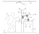
図7,8には、本発明の第二の実施形態としての安全装置80を備えたロボット協働装置82が示されている。以下の説明において、第一の実施形態と実質的に同一の部材および部位については、図中に同一の符号を付すことで説明を省略する。
7 and 8 show a robot cooperation device 82 including a safety device 80 as a second embodiment of the present invention. In the following description, members and portions that are substantially the same as those of the first embodiment are denoted by the same reference numerals in the drawings, and the description thereof is omitted.
すなわち、本実施形態の安全装置80は、ロボット14のアーム22が危険領域70へ進入したことを検出するライトカーテン56と、アーム22と作業者Aの接触を検出する衝突検出センサ36に加えて、作業者Aが共用作業台16の近くに位置することを検出する検出対象検出手段としてのエリアセンサ84を備えている。
That is, the safety device 80 according to the present embodiment includes the light curtain 56 that detects that the arm 22 of the robot 14 has entered the dangerous area 70 and the collision detection sensor 36 that detects contact between the arm 22 and the worker A. An area sensor 84 is provided as a detection target detecting means for detecting that the worker A is located near the shared work table 16.
エリアセンサ84は、共用作業台16における作業者A側(図7中の左側)の側面に設けられて、作業者A側へ向けて所定の範囲に及ぶ光線を投射するようになっており、当該光線を作業者Aが遮ることによって、作業者Aが共用作業台16の近くに位置することを検出可能とされている。
The area sensor 84 is provided on a side surface of the shared work table 16 on the worker A side (left side in FIG. 7), and projects a light beam that reaches a predetermined range toward the worker A side. It is possible to detect that the worker A is located near the common work table 16 by the worker A blocking the light beam.
エリアセンサ84の検出範囲86は、例えば、作業者Aが腕などを伸ばして共用作業台16上に設定された共用領域68に達し得る危険領域70に位置している場合に、作業者Aの存在を検出することができるように設定される。換言すれば、エリアセンサ84の検出範囲86は、作業者Aがエリアセンサ84の検出範囲86外に位置している状態において、作業者Aが共用領域68に進入し得ず、作業者Aとロボット14のアーム22との衝突が生じ得ないように設定されていることが望ましい。なお、エリアセンサ84の検出範囲86は、共用作業台16の外周側に広がる危険領域70を網羅するように設定されることが望ましいが、必ずしも危険領域70と一致している必要はなく、危険領域70よりも広い範囲で設定され得る。
The detection range 86 of the area sensor 84 is, for example, when the worker A is positioned in the danger area 70 where the arm A or the like is extended and can reach the common area 68 set on the common work table 16. It is set so that presence can be detected. In other words, the detection range 86 of the area sensor 84 is such that the worker A cannot enter the common area 68 when the worker A is located outside the detection range 86 of the area sensor 84. It is desirable that the setting is made so that a collision with the arm 22 of the robot 14 cannot occur. The detection range 86 of the area sensor 84 is preferably set so as to cover the dangerous area 70 that extends to the outer peripheral side of the shared workbench 16, but does not necessarily need to coincide with the dangerous area 70. It can be set in a wider range than the area 70.
もっとも、検出対象検出手段は、例示したような光学式のエリアセンサ84に限定されるものではなく、例えば、光線に代えて超音波を使用する超音波式のエリアセンサや、カメラによって撮影された映像を処理することで作業者Aの位置を特定するもの、床18に敷設されて作用する荷重に基づいて作業者Aの位置を特定するマットセンサなどを採用することもできる。
However, the detection target detection means is not limited to the optical area sensor 84 as illustrated, and is taken by, for example, an ultrasonic area sensor that uses ultrasonic waves instead of light rays or a camera. It is also possible to employ a sensor that identifies the position of the worker A by processing the video, a mat sensor that identifies the position of the worker A based on a load that is laid on the floor 18 and acts.
そして、本実施形態に係るロボット協働装置82の安全装置80では、センサ制御装置64が、ライトカーテン56がアーム22の共用領域68への進入を検出した検出信号と、エリアセンサ84が作業者Aの共用作業台16への接近を検出した検出信号とに基づいて、衝突検出センサ36による検出の有効と無効を切り替えるようになっている。
In the safety device 80 of the robot cooperation device 82 according to the present embodiment, the sensor control device 64 detects the detection signal that the light curtain 56 has entered the common area 68 of the arm 22 and the area sensor 84 is an operator. The detection by the collision detection sensor 36 is switched between valid and invalid based on the detection signal that detects the approach to the shared work table 16 of A.
すなわち、ロボット14のアーム22が共用領域68に位置していると共に、作業者Aが共用領域68に達し得る危険領域70に位置している場合には、共用領域68においてアーム22と作業者Aの衝突が生じ得ることから、センサ制御装置64が衝突検出センサ36による検出を有効として、衝突による危険を低減乃至は回避する。
That is, when the arm 22 of the robot 14 is located in the common area 68 and the worker A is located in the danger area 70 where the common area 68 can be reached, the arm 22 and the worker A in the common area 68. Therefore, the sensor control device 64 enables the detection by the collision detection sensor 36 to reduce or avoid the danger due to the collision.
一方、アーム22が共用領域68に位置していることがライトカーテン56によって検出されたとしても、作業者Aがエリアセンサ84の検出範囲86の外側に位置していることが検出された場合には、作業者Aが共用領域68に進入することがなく、共用領域68におけるアーム22と作業者Aの衝突は生じ得ない。それ故、この場合には、センサ制御装置64が衝突検出センサ36による検出を無効として、衝突検出センサ36の誤検出によるアーム22の不必要な停止を回避する。
On the other hand, even if it is detected by the light curtain 56 that the arm 22 is located in the common area 68, when it is detected that the worker A is located outside the detection range 86 of the area sensor 84. The worker A does not enter the common area 68, and the arm 22 and the worker A in the common area 68 cannot collide with each other. Therefore, in this case, the sensor control device 64 invalidates the detection by the collision detection sensor 36 and avoids unnecessary stop of the arm 22 due to erroneous detection of the collision detection sensor 36.
同様に、作業者Aがエリアセンサ84の検出範囲86内に位置していると共に、アーム22が共用領域68の外側に位置している場合にも、アーム22と作業者Aの衝突が生じ得ないことから、センサ制御装置64は衝突検出センサ36による検出を無効とする。
Similarly, when the worker A is located within the detection range 86 of the area sensor 84 and the arm 22 is located outside the common area 68, the arm 22 and the worker A may collide. Therefore, the sensor control device 64 invalidates the detection by the collision detection sensor 36.
このように、本実施形態によれば、ロボット14のアーム22が共用領域68に位置しているか否かだけでなく、作業者Aが危険領域70に位置し得るか否かも参照して、衝突検出センサ36による検出の有効と無効を切り替えることから、より衝突の危険性が大きい場合に限定して衝突検出センサ36を有効にすることができる。従って、衝突検出センサ36の誤検出によるアーム22の停止などがより有利に回避されて、ロボット14の作業効率の向上が効果的に実現される。
As described above, according to the present embodiment, not only whether or not the arm 22 of the robot 14 is located in the common area 68 but also whether or not the worker A can be located in the dangerous area 70 is determined. Since the detection by the detection sensor 36 is switched between valid and invalid, the collision detection sensor 36 can be validated only when the risk of collision is greater. Therefore, stopping of the arm 22 due to erroneous detection of the collision detection sensor 36 is more advantageously avoided, and improvement of the working efficiency of the robot 14 is effectively realized.
図9,10には、本発明の第三の実施形態としての安全装置90を備えるロボット協働装置92が示されている。
9 and 10 show a robot cooperation device 92 including a safety device 90 as a third embodiment of the present invention.
本実施形態では、ロボット14のアーム22と作業者Aの両方が進入し得る共用領域68が、図10中に一点鎖線で示した境界94を挟んだ両側である第一の区分領域96aと第二の区分領域96bによって構成されている。
In the present embodiment, the common area 68 into which both the arm 22 of the robot 14 and the worker A can enter is the first divided area 96a and the first divided area 96a on both sides of the boundary 94 shown by the one-dot chain line in FIG. It is constituted by two divided regions 96b.
さらに、安全装置90は、図9に示すように、区分領域検出手段としての撮像検出装置98を備えている。撮像検出装置98は、アーム22と作業者Aが第一の区分領域96aと第二の区分領域96bの何れに位置しているかを、例えば天井99に取り付けられたカメラ100によって上側(図9中の上側)から撮影した映像に基づいて検出するものである。この撮像検出装置98は、アーム22と作業者Aの両方が共用領域68に位置しているか否かと、アーム22と作業者Aが同じ区分領域96に位置しているか否かを検出して、検出信号をセンサ制御装置64へ送信するようになっている。
Furthermore, as shown in FIG. 9, the safety device 90 includes an imaging detection device 98 as a segmented region detection means. The imaging detection device 98 determines whether the arm 22 and the worker A are located in the first partitioned area 96a or the second partitioned area 96b by, for example, the camera 100 attached to the ceiling 99 (in FIG. 9). It is detected based on the video taken from above. The imaging detection device 98 detects whether both the arm 22 and the worker A are located in the common area 68, and whether the arm 22 and the worker A are located in the same divided area 96, A detection signal is transmitted to the sensor control device 64.
そして、アーム22と作業者Aが同じ区分領域96に位置している場合には、アーム22と作業者Aが衝突するおそれがあることから、センサ制御装置64が撮像検出装置98の検出信号に基づいて衝突検出センサ36による接触の検出を有効とする。これにより、アーム22と作業者Aの衝突時に、衝突検出センサ36の検出結果に基づいてアーム22が緊急停止せしめられて、衝突時の衝撃力が低減される。
When the arm 22 and the worker A are located in the same segmented area 96, the arm 22 and the worker A may collide, and therefore the sensor control device 64 uses the detection signal of the imaging detection device 98 as a detection signal. Based on this, the detection of contact by the collision detection sensor 36 is validated. As a result, when the arm 22 collides with the worker A, the arm 22 is urgently stopped based on the detection result of the collision detection sensor 36, and the impact force at the time of the collision is reduced.
一方、アーム22と作業者Aが互いに異なる区分領域96に位置している場合には、アーム22と作業者Aが衝突するおそれがないことから、センサ制御装置64が撮像検出装置98の検出信号に基づいて衝突検出センサ36による接触の検出を無効とする。これにより、衝突検出センサ36の誤検出に起因するアーム22の不必要な停止が回避されて、ロボット14の作業効率の向上が図られる。
On the other hand, when the arm 22 and the worker A are located in different divided areas 96, there is no possibility that the arm 22 and the worker A collide with each other, so that the sensor control device 64 detects the detection signal of the imaging detection device 98. Based on the above, the detection of contact by the collision detection sensor 36 is invalidated. Thereby, unnecessary stop of the arm 22 due to erroneous detection of the collision detection sensor 36 is avoided, and the work efficiency of the robot 14 is improved.
特に本実施形態では、アーム22と作業者Aの両方が共用領域68に位置している状態であっても、それらアーム22と作業者Aが第一の区分領域96aと第二の区分領域96bの各一方に位置している場合には、アーム22と作業者Aの衝突が生じないことから、衝突検出センサ36が無効とされる。それ故、衝突検出センサ36の誤検出によるアーム22の減速や停止がより効率よく回避されて、作業効率の向上が有利に実現される。
In particular, in the present embodiment, even when both the arm 22 and the worker A are located in the common area 68, the arm 22 and the worker A have the first divided area 96a and the second divided area 96b. Since the arm 22 and the worker A do not collide, the collision detection sensor 36 is invalidated. Therefore, deceleration and stop of the arm 22 due to erroneous detection of the collision detection sensor 36 can be avoided more efficiently, and work efficiency can be advantageously improved.
なお、第三の実施形態では、共用領域68が二つの区分領域96a,96bに区分けされた態様を例示したが、共用領域68を三つ以上の区分領域に区分けして、アーム22と作業者Aが一つの区分領域に位置している場合にのみ衝突検出センサ36を有効とすることもできる。
In the third embodiment, the common area 68 is divided into two divided areas 96a and 96b. However, the shared area 68 is divided into three or more divided areas, and the arm 22 and the worker are separated. The collision detection sensor 36 can be validated only when A is located in one segmented area.
さらに、第三の実施形態では、共用領域68が平面的に二つの区分領域96a,96bに区分けされた態様を例示したが、共用領域68を高さ方向(図9中の上下方向)でも区分けして、高さ方向でアーム22と作業者Aが同じ区分領域に位置しているか否かを検出するようにしても良い。なお、第三の実施形態で示した共用領域68の平面的な区分けと、上記した共用領域68の高さ方向での区分けとを組み合わせて、複数の区分領域を三次元的に配することもできる。
Furthermore, in the third embodiment, an example in which the shared area 68 is planarly divided into two divided areas 96a and 96b is illustrated. However, the shared area 68 is also divided in the height direction (vertical direction in FIG. 9). Then, it may be detected whether the arm 22 and the worker A are located in the same section area in the height direction. It is also possible to arrange a plurality of divided areas in a three-dimensional manner by combining the planar division of the shared area 68 shown in the third embodiment and the above-described division of the shared area 68 in the height direction. it can.
また、共用領域68を複数に区分けすることなく、アーム22と作業者Aの両方が共用領域68に位置しているか否かを、撮像検出装置98によって検出するようにしても良い。これによれば、アーム22と作業者Aの両方が共用領域68に位置していることを検出した場合に、衝突の危険性があると判定して衝突検出センサ36を有効にすることで、十分な安全性の確保と優れた作業効率とを両立して実現できると共に、撮像検出装置98において映像処理の簡単化などが図られ得る。
Further, it may be detected by the imaging detection device 98 whether or not both the arm 22 and the worker A are located in the common area 68 without dividing the common area 68 into a plurality. According to this, when it is detected that both the arm 22 and the worker A are located in the common area 68, it is determined that there is a risk of collision, and the collision detection sensor 36 is enabled, Ensuring sufficient safety and excellent work efficiency can be realized at the same time, and image processing can be simplified in the imaging detection device 98.
また、第三の実施形態では、区分領域検出手段としての撮像検出装置98によって、アーム22と作業者Aが何れの区分領域96に進入しているかを検出可能とされていたが、区分領域検出手段は、撮像検出装置98のようなカメラ100による撮影映像を利用するものに限定されない。
Further, in the third embodiment, the imaging detection device 98 as the divided area detection means can detect which divided area 96 the arm 22 and the worker A have entered. The means is not limited to one that uses a video image taken by the camera 100 such as the imaging detection device 98.
具体的には、例えば、アーム22が何れの区分領域96に位置しているかを検出する区分領域検出手段として、アーム22の関節部26の角度を検出する角度センサなどを採用すると共に、作業者Aが何れの区分領域96に位置しているかを検出する区分領域検出手段として、床18に敷設されるマットセンサなどを採用することもできる。この場合には、作業者Aの床18上での位置はマットセンサに作用する荷重に基づいて検出可能であるが、作業者Aの姿勢(例えば作業者Aが手をどちら向きに伸ばしているかなど)を検出できないことから、例えば、作業者Aの検出位置に基づいて作業者Aの手などが到達可能であると推定される範囲の全体を作業者Aの位置として、衝突検出センサ36による検出の要否を判定する。従って、作業者Aが第一,第二の区分領域96a,96bの両方に到達可能な位置でマットセンサによって検出された場合には、第一,第二の区分領域96a,96bの何れかに対するアーム22の進入が検出されることで、衝突検出センサ36による検出が有効になる。
Specifically, for example, an angle sensor or the like that detects the angle of the joint portion 26 of the arm 22 is employed as a segmented region detection unit that detects in which segmented region 96 the arm 22 is located. A mat sensor or the like laid on the floor 18 may be employed as the segment area detecting means for detecting which segment area 96 A is located in. In this case, the position of the worker A on the floor 18 can be detected based on the load acting on the mat sensor, but the posture of the worker A (for example, the direction in which the worker A extends the hand) For example, based on the detection position of the worker A, the collision detection sensor 36 uses the entire range estimated to be reachable by the worker A as the position of the worker A. The necessity of detection is determined. Accordingly, when the worker A is detected by the mat sensor at a position where the worker A can reach both the first and second divided regions 96a and 96b, the worker A is directed to either the first or second divided region 96a or 96b. By detecting the approach of the arm 22, the detection by the collision detection sensor 36 becomes effective.
ところで、図10に一点鎖線で示すように、第一,第二の区分領域96a,96bの周囲に第一,第二の進入予測領域102a,102bを設定して、アーム22と作業者Aの両方が第一,第二の進入予測領域102a,102bの何れか一方に進入したことを撮像検出装置98によって検出した場合に、アーム22および作業者Aが同じ区分領域96に進入しようとしていると判定して、衝突検出センサ36を有効にすることもできる。要するに、第三の実施形態では、アーム22と作業者Aの両方が一つの区分領域96に進入した状態を進入と略同時に検出する構成に限定されず、アーム22と作業者Aの両方が一つの区分領域96に進入しようとしていることを進入前に検出する構成を採用することもできる。
By the way, as shown by the one-dot chain line in FIG. 10, the first and second approach prediction areas 102a and 102b are set around the first and second segment areas 96a and 96b, and the arm 22 and the operator A's When the imaging detection device 98 detects that both have entered one of the first and second approach prediction areas 102a and 102b, the arm 22 and the worker A are about to enter the same section area 96. It is also possible to validate the collision detection sensor 36. In short, in the third embodiment, the present invention is not limited to the configuration in which both the arm 22 and the worker A detect the state in which the arm 22 and the worker A have entered one segmented region 96 almost simultaneously with the entry, and both the arm 22 and the worker A have one It is also possible to adopt a configuration in which it is detected before entering that one of the two divided areas 96 is about to enter.
上記のような第一,第二の進入予測領域102a,102bを設ける場合には、撮像検出装置98がアーム22および作業者Aが第一,第二の進入予測領域102a,102bの何れか一方に進入したことを検出して、撮像検出装置98の検出結果からアーム22および作業者Aの同じ区分領域96への進入が予測される場合に、センサ制御装置64が撮像検出装置98の検出信号に基づいて衝突検出センサ36を有効にする。一方、撮像検出装置98が、アーム22と作業者Aが第一,第二の進入予測領域102a,102bの各一方に進入したことや、アーム22と作業者Aの少なくとも一方が第一,第二の進入予測領域102a,102bの何れにも進入していないことを検出して、撮像検出装置98の検出結果からアーム22および作業者Aの同じ区分領域96への進入が予測されない場合には、センサ制御装置64が撮像検出装置98の検出信号に基づいて衝突検出センサ36を無効にする。
When providing the first and second approach prediction areas 102a and 102b as described above, the imaging detection device 98 is either the arm 22 and the operator A is one of the first or second approach prediction areas 102a and 102b. Is detected, and the sensor control device 64 detects the detection signal of the imaging detection device 98 when the detection result of the imaging detection device 98 predicts the entry of the arm 22 and the worker A into the same segmented region 96. The collision detection sensor 36 is validated based on the above. On the other hand, the imaging detection device 98 indicates that the arm 22 and the worker A have entered one of the first and second approach prediction areas 102a and 102b, and that at least one of the arm 22 and the worker A is the first and second. When it is detected that the vehicle has not entered any of the two predicted entry areas 102a and 102b, and it is not predicted that the arm 22 and the worker A will enter the same divided area 96 from the detection result of the imaging detection device 98. The sensor control device 64 invalidates the collision detection sensor 36 based on the detection signal of the imaging detection device 98.
このような第一,第二の進入予測領域102a,102bを備えた態様によれば、アーム22および作業者Aが一つの区分領域96へ進入することを予測して衝突検出センサ36を有効にすることで、例えば、アーム22および作業者Aが一つの区分領域96への進入と略同時に衝突した場合などにも、衝突に対する安全性を確保することができる。
According to such an aspect including the first and second approach prediction areas 102a and 102b, the collision detection sensor 36 is made effective by predicting that the arm 22 and the worker A enter the one section area 96. By doing so, for example, even when the arm 22 and the worker A collide almost simultaneously with the entry into one sectioned region 96, safety against the collision can be ensured.
なお、このようなアーム22および作業者Aの特定領域への進入を進入前に検出して、衝突検出センサ36を進入前に有効とする態様は、必ずしも第三の実施形態の区分領域96に対してのみ適用されるものではなく、他の領域への進入を検出する場合にも、領域への進入前の検出が可能である。例えば、境界94で区分けされていない共用領域68に対するアーム22および作業者Aの進入を検出する場合には、共用領域68の周囲に進入予測領域102を設定することで、アーム22および作業者Aの共用領域68への進入を進入前に検出することができる。また、例えば、第一の実施形態において、危険領域70からロボット14に近い側へ離れた位置にライトカーテン56を配することによって、アーム22の危険領域70への進入をライトカーテン56で進入前に検出することもできる。
In addition, the aspect which detects the approach to the specific area | region of such an arm 22 and the worker A before approaching and makes the collision detection sensor 36 effective before approaching is not necessarily in the division area 96 of 3rd embodiment. However, the present invention is not applied only to the case, and even when an entry to another area is detected, detection before entering the area is possible. For example, when detecting the approach of the arm 22 and the worker A to the common area 68 that is not separated by the boundary 94, the arm 22 and the worker A are set by setting the approach prediction area 102 around the common area 68. It is possible to detect entry into the common area 68 before entering. Further, for example, in the first embodiment, the light curtain 56 is arranged at a position away from the danger area 70 toward the side closer to the robot 14, so that the arm 22 enters the danger area 70 before entering the light curtain 56. It can also be detected.
以上、本発明の実施形態について詳述してきたが、本発明はその具体的な記載によって限定されない。例えば、衝突検出手段を構成する衝突検出センサ36としては、接触検出センサに代えて或いは加えて、作業者Aの接近をアーム22への接触前に検出可能な接近検出センサを採用することもできる。この接近検出センサは、例えば、第一の実施形態で示した静電容量型センサや電気抵抗型センサなどの検出精度を調節することによっても実現可能であるし、赤外線センサなどの接触検出センサとは別構造のセンサとすることもできる。
As mentioned above, although embodiment of this invention has been explained in full detail, this invention is not limited by the specific description. For example, as the collision detection sensor 36 constituting the collision detection means, an approach detection sensor that can detect the approach of the worker A before contacting the arm 22 can be employed instead of or in addition to the contact detection sensor. . This proximity detection sensor can be realized by adjusting the detection accuracy of the capacitance type sensor or the electric resistance type sensor shown in the first embodiment. Can be a sensor of another structure.
このように衝突検出センサ36として接近検出センサを採用する場合には、接近検出センサの検出信号に基づいたアーム22と作業者Aの接近判定の結果に応じて、アーム制御装置54がアーム22の移動速度を調節する。これにより、アーム22と作業者Aの接触よりも前に衝突に備えたアーム22の減速や停止が可能となって、アーム22と作業者Aの衝突時の衝撃力をより小さくできると共に、衝突を未然に防ぐことも可能となり得る。なお、アーム22と作業者Aの接近を検出した接近検出センサの検出信号に基づいてアーム22を減速させた後で、アーム22と作業者Aが離れて、接近検出センサによるアーム22と作業者Aの接近検出が解除される場合には、接近検出センサの検出信号がないことに基づいて、アーム制御装置54がアーム22を減速前の移動速度まで加速するようにしても良い。
Thus, when the proximity detection sensor is employed as the collision detection sensor 36, the arm control device 54 determines whether the arm 22 is in accordance with the result of the approach determination between the arm 22 and the worker A based on the detection signal of the proximity detection sensor. Adjust the moving speed. As a result, the arm 22 can be decelerated and stopped in preparation for the collision before the contact between the arm 22 and the worker A, and the impact force at the time of the collision between the arm 22 and the worker A can be further reduced. It can also be possible to prevent this. In addition, after decelerating the arm 22 based on the detection signal of the approach detection sensor that detects the approach of the arm 22 and the worker A, the arm 22 and the worker A are separated and the arm 22 and the worker by the approach detection sensor are separated. When the approach detection of A is canceled, the arm control device 54 may accelerate the arm 22 to the moving speed before deceleration based on the absence of the detection signal of the approach detection sensor.
前記実施形態では、複数の圧力検出部52を備えて面圧分布を測定可能な衝突検出センサ36を例示したが、例えば、接触の方向などを把握する必要がない場合などには、リンク24の表面全体を覆う一つの圧力検出部52だけを備えた接触検出センサを採用することもできる。
In the above-described embodiment, the collision detection sensor 36 that includes the plurality of pressure detection units 52 and can measure the surface pressure distribution is illustrated. However, for example, when it is not necessary to grasp the contact direction, the link 24 A contact detection sensor including only one pressure detection unit 52 that covers the entire surface may be employed.
前記実施形態では、移動部検出手段としてライトカーテン56を例示したが、例えば、カメラによって撮影される映像、角度センサによって検出されたアーム22の各関節部26の角度、距離センサによって検出されたアーム22と共用作業台16の距離などに基づいて、アーム22の共用領域68への進入を検出することもできる。
In the above-described embodiment, the light curtain 56 is exemplified as the moving unit detecting unit. However, for example, an image captured by a camera, an angle of each joint portion 26 of the arm 22 detected by an angle sensor, and an arm detected by a distance sensor. The approach of the arm 22 into the common area 68 can also be detected based on the distance between the common work platform 16 and the arm 22.
また、前記実施形態に示したアーム進入エリア66や共用領域68、危険領域70などは、あくまでも例示であって、作業内容や作業スペースなどに応じて適宜に設定される。また、例えば、共用領域68は、必ずしも共用作業台16上に設定される態様に限定されない。
Further, the arm entry area 66, the common area 68, the dangerous area 70, and the like shown in the above embodiment are merely examples, and are appropriately set according to the work content and the work space. Further, for example, the shared area 68 is not necessarily limited to a mode set on the shared work table 16.
前記実施形態では、衝突検出手段によって検出する検出対象として作業者Aを例示したが、検出対象は人に限定されず、物であっても良い。また、検出対象の移動部への接触時に作用する力を低減するために、弾性クッション層34のような緩衝材が移動部に設けられていることが望ましいが、弾性クッション層34は必須ではない。
In the above embodiment, the worker A is exemplified as the detection target detected by the collision detection means, but the detection target is not limited to a person, and may be an object. Further, in order to reduce the force acting upon contact with the moving part to be detected, it is desirable that a cushioning material such as the elastic cushion layer 34 is provided on the moving part, but the elastic cushion layer 34 is not essential. .
また、衝突検出手段が装着される自動装置は、前記実施形態に示した産業用ロボットに限定されず、例えば、医療用乃至は介護用のロボットや無人搬送車(AGV)などであっても良い。なお、前記実施形態では、自動装置の一部であるアーム22が移動部とされる構造を例示したが、例えば自動装置がAGVである場合には、自動装置の全体が移動部とされる。
The automatic device to which the collision detection means is attached is not limited to the industrial robot shown in the above embodiment, and may be, for example, a medical or nursing robot or an automated guided vehicle (AGV). . In the above embodiment, the structure in which the arm 22 that is a part of the automatic device is the moving unit is illustrated. However, for example, when the automatic device is an AGV, the entire automatic device is the moving unit.
10,80,90:安全装置、14:ロボット(自動装置)、22:アーム(移動部)、36:衝突検出センサ(衝突検出手段、接触検出センサ、接近検出センサ)、54:アーム制御装置(移動部制御装置、速度制御装置)、56:ライトカーテン(危険状態検出手段、移動部検出手段)、64:センサ制御装置(衝突検出制御装置)、68:共用領域、70:危険領域、84:エリアセンサ(検出対象検出手段)、96a:第一の区分領域、96b:第二の区分領域
10, 80, 90: safety device, 14: robot (automatic device), 22: arm (moving unit), 36: collision detection sensor (collision detection means, contact detection sensor, approach detection sensor), 54: arm control device ( Moving part control device, speed control device) 56: Light curtain (dangerous state detection means, moving part detection means), 64: Sensor control device (collision detection control device), 68: Shared area, 70: Dangerous area, 84: Area sensor (detection target detection means), 96a: first partitioned area, 96b: second partitioned area
Claims (8)
- 自動装置に設けられた移動部と移動可能な検出対象との衝突による危険を防止する安全装置であって、
前記自動装置の前記移動部には前記検出対象の接近乃至は接触を検出する衝突検出手段が設けられていると共に、該衝突検出手段の検出信号に基づいて該移動部の移動を加減速又は停止する移動部制御装置が設けられている一方、
該自動装置の該移動部と該検出対象とが衝突し得る危険領域が設定されていると共に、該移動部と該検出対象の少なくとも一方が該危険領域に位置するか否かを検出する危険状態検出手段が設けられており、
該衝突検出手段による該移動部と該検出対象の接近乃至は接触の検出を該危険状態検出手段の検出信号に基づいて有効又は無効とする衝突検出制御装置が設けられていることを特徴とする安全装置。 A safety device for preventing a danger caused by a collision between a moving part provided in an automatic device and a movable detection target,
The moving part of the automatic device is provided with a collision detection means for detecting the approach or contact of the detection target, and the movement of the moving part is accelerated / decelerated or stopped based on the detection signal of the collision detection means. While a moving unit control device is provided,
A dangerous state in which a dangerous region where the moving unit and the detection target of the automatic device may collide is set, and at least one of the moving unit and the detection target is detected in the dangerous region Detection means are provided,
There is provided a collision detection control device for enabling or disabling detection of the approach or contact between the moving part and the detection target by the collision detection means based on a detection signal of the dangerous state detection means. Safety device. - 前記危険状態検出手段が前記危険領域に対する前記移動部の進入を検出する移動部検出手段を含んでいる請求項1に記載の安全装置。 2. The safety device according to claim 1, wherein the dangerous state detecting means includes a moving part detecting means for detecting an approach of the moving part to the dangerous area.
- 前記危険状態検出手段が前記危険領域に対する前記検出対象の進入を検出する検出対象検出手段を含んでいる請求項1又は2に記載の安全装置。 3. The safety device according to claim 1 or 2, wherein the dangerous state detection means includes detection target detection means for detecting an approach of the detection target to the dangerous area.
- 前記危険領域は前記自動装置の前記移動部と前記検出対象との両方が進入可能な共用領域を含んでおり、前記危険状態検出手段は該移動部と該検出対象の両方の該共用領域に対する進入を検出する請求項1~3の何れか一項に記載の安全装置。 The dangerous area includes a common area where both the moving part and the detection target of the automatic device can enter, and the dangerous state detection means enters both the moving part and the detection target into the common area. The safety device according to any one of claims 1 to 3, wherein the safety device is detected.
- 前記共用領域が複数の区分領域によって構成されていると共に、前記危険状態検出手段は該移動部と該検出対象の一つの該区分領域に対する進入を検出する請求項4に記載の安全装置。 The safety device according to claim 4, wherein the common area is configured by a plurality of divided areas, and the dangerous state detecting means detects an entry of the moving unit and the detection target into one of the divided areas.
- 前記衝突検出手段が前記検出対象の前記移動部に対する接触を検出する接触検出センサを有しており、該接触検出センサがそれら移動部と検出対象の接触を検出した場合に該接触検出センサの検出信号に基づいて前記移動部制御装置が該移動部を停止するようにした請求項1~5の何れか一項に記載の安全装置。 The collision detection means has a contact detection sensor for detecting contact of the detection target with the moving part, and the contact detection sensor detects when the contact detection sensor detects contact between the movement part and the detection target. The safety device according to any one of claims 1 to 5, wherein the moving unit control device stops the moving unit based on a signal.
- 前記衝突検出手段が前記検出対象の前記移動部に対する接近を検出する接近検出センサを有しており、該接近検出センサがそれら移動部と検出対象の接近を検出した場合に該接近検出センサの検出信号に基づいて前記移動部制御装置が該移動部の移動を減速するようにした請求項1~6の何れか一項に記載の安全装置。 The collision detection means has an approach detection sensor for detecting the approach of the detection object to the moving part, and the approach detection sensor detects the approach when the approach detection sensor detects the approach of the movement part to the detection object. The safety device according to any one of claims 1 to 6, wherein the moving unit control device decelerates the movement of the moving unit based on a signal.
- 前記移動部の移動速度を前記危険状態検出手段の検出信号に基づいて調節する速度制御装置が設けられている請求項1~7の何れか一項に記載の安全装置。 The safety device according to any one of claims 1 to 7, further comprising a speed control device that adjusts a moving speed of the moving unit based on a detection signal of the dangerous state detecting means.
Priority Applications (3)
| Application Number | Priority Date | Filing Date | Title |
|---|---|---|---|
| EP18818924.5A EP3608068A4 (en) | 2017-06-13 | 2018-02-15 | Safety device |
| CN201880029889.2A CN110603123A (en) | 2017-06-13 | 2018-02-15 | Safety device |
| US16/565,413 US20200001460A1 (en) | 2017-06-13 | 2019-09-09 | Safety device |
Applications Claiming Priority (2)
| Application Number | Priority Date | Filing Date | Title |
|---|---|---|---|
| JP2017-116252 | 2017-06-13 | ||
| JP2017116252A JP2019000930A (en) | 2017-06-13 | 2017-06-13 | Safety device |
Related Child Applications (1)
| Application Number | Title | Priority Date | Filing Date |
|---|---|---|---|
| US16/565,413 Continuation US20200001460A1 (en) | 2017-06-13 | 2019-09-09 | Safety device |
Publications (1)
| Publication Number | Publication Date |
|---|---|
| WO2018230036A1 true WO2018230036A1 (en) | 2018-12-20 |
Family
ID=64660602
Family Applications (1)
| Application Number | Title | Priority Date | Filing Date |
|---|---|---|---|
| PCT/JP2018/005198 WO2018230036A1 (en) | 2017-06-13 | 2018-02-15 | Safety device |
Country Status (5)
| Country | Link |
|---|---|
| US (1) | US20200001460A1 (en) |
| EP (1) | EP3608068A4 (en) |
| JP (1) | JP2019000930A (en) |
| CN (1) | CN110603123A (en) |
| WO (1) | WO2018230036A1 (en) |
Cited By (2)
| Publication number | Priority date | Publication date | Assignee | Title |
|---|---|---|---|---|
| EP3725183A1 (en) * | 2019-04-18 | 2020-10-21 | Loctek Inc. | Electric lift table control system and method for resistance back-off |
| EP3978210A4 (en) * | 2019-05-28 | 2023-02-22 | OMRON Corporation | Safety monitoring system, safety monitoring control device, and safety monitoring method |
Families Citing this family (7)
| Publication number | Priority date | Publication date | Assignee | Title |
|---|---|---|---|---|
| JP6850538B2 (en) * | 2016-02-08 | 2021-03-31 | 川崎重工業株式会社 | Working robot |
| JP6922486B2 (en) * | 2017-07-06 | 2021-08-18 | 株式会社デンソーウェーブ | Robot control device |
| JP7243603B2 (en) * | 2019-12-09 | 2023-03-22 | トヨタ自動車株式会社 | Transfer robot system |
| JP7421346B2 (en) * | 2020-01-17 | 2024-01-24 | 川崎重工業株式会社 | Safety equipment, self-propelled robot system, and control method |
| US11897706B2 (en) | 2021-03-30 | 2024-02-13 | Dexterity, Inc. | Robotic system with zone-based control |
| US20220315353A1 (en) * | 2021-03-30 | 2022-10-06 | Dexterity, Inc. | Robotic line kitting system safety features |
| CN113369709A (en) * | 2021-06-10 | 2021-09-10 | 广东宏石激光技术股份有限公司 | Method and system for reducing brake impact of exchange |
Citations (5)
| Publication number | Priority date | Publication date | Assignee | Title |
|---|---|---|---|---|
| JPS585208B2 (en) | 1973-07-18 | 1983-01-29 | モンテジソン ソシエタ パ− アシオネ | 1-Aza-2-Hydroxybenzanthrone |
| JPH05345293A (en) * | 1992-06-15 | 1993-12-27 | Yaskawa Electric Corp | Collision prevention of industrial robot |
| JP2010188515A (en) * | 2009-01-26 | 2010-09-02 | Fanuc Ltd | Production system having cooperating process area between human and robot |
| JP2010234495A (en) * | 2009-03-31 | 2010-10-21 | National Institute Of Advanced Industrial Science & Technology | Safety controller, robot, system, program and recording medium |
| WO2016103308A1 (en) * | 2014-12-26 | 2016-06-30 | 川崎重工業株式会社 | Robot system |
Family Cites Families (7)
| Publication number | Priority date | Publication date | Assignee | Title |
|---|---|---|---|---|
| US5280622A (en) * | 1992-07-17 | 1994-01-18 | Mitsubishi Semiconductor America, Inc. | Combined light beam and ultrasonic transducer safety sensing system |
| JP5035768B2 (en) * | 2006-04-18 | 2012-09-26 | 独立行政法人産業技術総合研究所 | Safety device for human robot coexistence work |
| CN104428107B (en) * | 2012-07-10 | 2016-06-29 | 西门子公司 | The method that robot arranges and is used for controlling robot |
| DE202013105036U1 (en) * | 2013-11-08 | 2015-02-10 | Daimler Ag | detector |
| JP6517567B2 (en) * | 2015-03-31 | 2019-05-22 | 日本電産サンキョー株式会社 | Servo motor control device and collision detection method |
| JP6678396B2 (en) * | 2015-05-19 | 2020-04-08 | アズビル株式会社 | Collision detection device |
| DE102015114463A1 (en) * | 2015-08-31 | 2017-03-02 | Kuka Systems Gmbh | Safety device and safety procedures |
-
2017
- 2017-06-13 JP JP2017116252A patent/JP2019000930A/en not_active Withdrawn
-
2018
- 2018-02-15 WO PCT/JP2018/005198 patent/WO2018230036A1/en unknown
- 2018-02-15 CN CN201880029889.2A patent/CN110603123A/en not_active Withdrawn
- 2018-02-15 EP EP18818924.5A patent/EP3608068A4/en not_active Withdrawn
-
2019
- 2019-09-09 US US16/565,413 patent/US20200001460A1/en not_active Abandoned
Patent Citations (5)
| Publication number | Priority date | Publication date | Assignee | Title |
|---|---|---|---|---|
| JPS585208B2 (en) | 1973-07-18 | 1983-01-29 | モンテジソン ソシエタ パ− アシオネ | 1-Aza-2-Hydroxybenzanthrone |
| JPH05345293A (en) * | 1992-06-15 | 1993-12-27 | Yaskawa Electric Corp | Collision prevention of industrial robot |
| JP2010188515A (en) * | 2009-01-26 | 2010-09-02 | Fanuc Ltd | Production system having cooperating process area between human and robot |
| JP2010234495A (en) * | 2009-03-31 | 2010-10-21 | National Institute Of Advanced Industrial Science & Technology | Safety controller, robot, system, program and recording medium |
| WO2016103308A1 (en) * | 2014-12-26 | 2016-06-30 | 川崎重工業株式会社 | Robot system |
Non-Patent Citations (1)
| Title |
|---|
| See also references of EP3608068A4 * |
Cited By (2)
| Publication number | Priority date | Publication date | Assignee | Title |
|---|---|---|---|---|
| EP3725183A1 (en) * | 2019-04-18 | 2020-10-21 | Loctek Inc. | Electric lift table control system and method for resistance back-off |
| EP3978210A4 (en) * | 2019-05-28 | 2023-02-22 | OMRON Corporation | Safety monitoring system, safety monitoring control device, and safety monitoring method |
Also Published As
| Publication number | Publication date |
|---|---|
| EP3608068A4 (en) | 2020-07-15 |
| EP3608068A1 (en) | 2020-02-12 |
| US20200001460A1 (en) | 2020-01-02 |
| CN110603123A (en) | 2019-12-20 |
| JP2019000930A (en) | 2019-01-10 |
Similar Documents
| Publication | Publication Date | Title |
|---|---|---|
| WO2018230036A1 (en) | Safety device | |
| WO2018173380A1 (en) | Sensor device | |
| JP6687573B2 (en) | Robot system | |
| JP4648486B2 (en) | Production system with cooperative operation area between human and robot | |
| US20190368950A1 (en) | Sensor device | |
| JP6392910B2 (en) | Human collaborative robot system with robot safety ensuring function | |
| US9669548B2 (en) | Mobile collaborative robot | |
| JP6364096B2 (en) | Robot system | |
| US10828791B2 (en) | Human-cooperative industrial robot including protection member | |
| WO2018173366A1 (en) | Sensor device | |
| JP7329902B2 (en) | ROBOT CONTROL DEVICE, ROBOT SYSTEM, ROBOT CONTROL METHOD, AND ROBOT CONTROL PROGRAM | |
| JP2012040626A (en) | Human cooperation robot system | |
| KR20100023722A (en) | Self-controlling movement device | |
| JP2018103345A (en) | Robot system | |
| JP6008612B2 (en) | Wirelessly operated vehicle remote control system | |
| JP2022516903A (en) | Replenishment collision detection and prevention system for medical imaging equipment | |
| CN112192617A (en) | Anti-collision control method of multi-truss transmission system and multi-truss transmission system | |
| CN113246831A (en) | Operation system | |
| US20190091864A1 (en) | Robot system | |
| JP2005059161A (en) | Robot control device | |
| CN110576455B (en) | Modularized collision detection and protection device for multi-degree-of-freedom image robot | |
| CN209514412U (en) | A kind of AGV active safety protection whole system | |
| JP6448474B2 (en) | Pressure sensor and robot with pressure sensor | |
| WO2020090342A1 (en) | Sensor device | |
| WO2021193932A1 (en) | Electrostatic capacitance sensor, sensor unit, and robot |
Legal Events
| Date | Code | Title | Description |
|---|---|---|---|
| 121 | Ep: the epo has been informed by wipo that ep was designated in this application |
Ref document number: 18818924 Country of ref document: EP Kind code of ref document: A1 |
|
| NENP | Non-entry into the national phase |
Ref country code: DE |