WO2018225504A1 - 吸引装置 - Google Patents
吸引装置 Download PDFInfo
- Publication number
- WO2018225504A1 WO2018225504A1 PCT/JP2018/019756 JP2018019756W WO2018225504A1 WO 2018225504 A1 WO2018225504 A1 WO 2018225504A1 JP 2018019756 W JP2018019756 W JP 2018019756W WO 2018225504 A1 WO2018225504 A1 WO 2018225504A1
- Authority
- WO
- WIPO (PCT)
- Prior art keywords
- container
- suction device
- suction
- hole
- pump
- Prior art date
- Legal status (The legal status is an assumption and is not a legal conclusion. Google has not performed a legal analysis and makes no representation as to the accuracy of the status listed.)
- Ceased
Links
Images


Classifications
-
- A—HUMAN NECESSITIES
- A61—MEDICAL OR VETERINARY SCIENCE; HYGIENE
- A61C—DENTISTRY; APPARATUS OR METHODS FOR ORAL OR DENTAL HYGIENE
- A61C17/00—Devices for cleaning, polishing, rinsing or drying teeth, teeth cavities or prostheses; Saliva removers; Dental appliances for receiving spittle
- A61C17/06—Saliva removers; Accessories therefor
- A61C17/065—Saliva removers; Accessories therefor characterised by provisions for processing the collected matter, e.g. for separating solids or air
Definitions
- the present invention relates to a suction device used for cleaning the oral cavity.
- suction devices include a device body with a built-in suction pump, and a container for storing aspirated material (intraoral cleaning fluid, eating bowl, etc.) sucked by the suction force of the suction pump.
- the container is detachably provided.
- a motor-driven pump such as a rotary pump
- a large pump must be used. For this reason, many conventional suction devices are large and heavy (see, for example, Patent Documents 1 and 2).
- the suction device itself tends to collapse. For example, there is a possibility that a tube connected to the suction device is pulled during use and the suction device falls, or the suction device is fallen due to accumulation of aspirated material in the container and a change in the center of gravity. When the suction device falls down, the suction material stored in the container flows toward the suction pump, which may cause the suction pump to break down.
- an object of the present invention is to provide a suction device that achieves downsizing and is less likely to cause adverse effects due to downsizing.
- the suction device includes a suction pump, a container, and a container.
- the accommodating body accommodates the suction pump and has an intake hole communicating with the suction pump.
- the container has an exhaust hole connected to the intake hole and an inflow hole into which the suctioned material flows. Then, in a top view, the container and the container are arranged side by side in the first direction, the occupied area of the container is smaller than the occupied area of the container, and in the second direction perpendicular to both the first direction and the vertical direction
- the maximum width of the container is smaller than the maximum width of the container.
- the size of the container is smaller than that of the container by making the occupied area of the container smaller than the occupied area of the container in a top view.
- the container and the container are arranged side by side in the first direction when viewed from above, and the maximum width of the container is made smaller than the maximum width of the container in the second direction.
- the full width tends to be smaller than the full width in the first direction. Therefore, even if the suction device falls down for some reason, the direction in which the suction device falls is easily regulated in a narrow direction (the same direction as the second direction or the opposite direction) in the suction device.
- the full width in the second direction of the container and the container is smaller than the full width in the first direction. According to this configuration, even if the suction device falls down for some reason, the direction in which the suction device falls is easily restricted to a narrow direction (the same direction as the second direction or the opposite direction) in the suction device.
- the maximum width of the container is smaller than the maximum width of the container in the first direction. According to this configuration, the size of the container is smaller than that of the container.
- the exhaust hole is disposed in a central region in the second direction of the upper surface of the container after the direction of falling is regulated as described above. According to this configuration, even when the suction device falls, the exhaust hole is arranged at a position about half the maximum width from the lower end position of the container when the suction device falls. For this reason, even when the suction device falls down, the suction material stored in the container is difficult to reach the exhaust hole, and therefore, the suction material can be prevented from flowing to the suction hole side.
- the container has a shape in which the width in the second direction becomes smaller as the container is separated from the container.
- the side surface of the container opposite to the container is tapered toward the first direction. Therefore, when the posture in which the container is under the container is considered as the posture in which the suction device has fallen, the posture becomes unstable because the tapered side faces down. . Therefore, even if the suction device falls down for some reason, the fallen posture is easily restricted to a posture in which the container and the container are arranged side by side (posture in the same direction as or in the opposite direction to the second direction).
- the suction device according to the present invention further includes a protruding portion coupled to the container and protruding to the opposite side of the container.
- the protrusion serves as a support when the suction device is about to fall in the first direction. Therefore, the protrusion functions as one of means for regulating the direction in which the suction device falls.
- the suction device according to the present invention further includes a hold unit coupled to the container, and the container is held in a predetermined positional relationship with respect to the container by the hold unit.
- a container and a container can be unitized.
- the distance between the exhaust hole and the intake hole is shorter than the distance between the inflow hole and the intake hole. According to this configuration, piping such as a tube connecting the exhaust hole and the intake hole can be shortened, and as a result, pressure loss between the exhaust hole and the intake hole can be reduced.
- the suction pump is disposed on the upper part of the container. According to this configuration, the suction pump approaches the exhaust hole provided in the container. Therefore, the pressure loss between the exhaust hole and the suction pump can be reduced.
- the suction pump has a flat plate shape, and its main plane faces the side surface of the container. According to this configuration, the width of the container in the first direction can be reduced according to the thickness of the suction pump.
- the suction pump is preferably a piezoelectric pump. According to this configuration, the suction pump can be significantly reduced in size, thickness, and weight as compared with the conventional motor-driven pump.
- the suction device according to the present invention further includes a mounting table on which the container is mounted and coupled to the lower part of the container, and a power supply unit provided inside the mounting table.
- a relatively heavy battery can be disposed in the lower portion of the suction device as the power supply unit. Thereby, the gravity center of the suction device can be lowered, and as a result, the suction device can be made difficult to fall.
- downsizing is realized and adverse effects due to downsizing are less likely to occur.
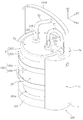
- FIG. 1 is a perspective view conceptually showing the suction device according to the first embodiment.
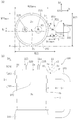
- FIG. 2A is a top view conceptually showing the suction device according to the first embodiment, and
- FIG. 2B is a side view conceptually showing the suction device.
- FIG. 3 is a perspective view in which the inside of the container is exposed by omitting a part of the container included in the suction device.
- FIG. 4 is a perspective view conceptually showing the suction device according to the second embodiment.
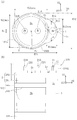
- FIG. 5A is a top view conceptually showing the suction device according to the second embodiment, and FIG. 5B is a side view conceptually showing the suction device.
- FIG. 1 is a perspective view conceptually showing a suction device according to a first embodiment.
- 2A and 2B are a top view and a side view conceptually showing the suction device, respectively.
- the suction device includes a housing 1 that houses a suction pump P (see FIG. 3), and a container 2 that stores a suction object.
- the container 1 and the container 2 are arrange
- the first direction D1 is a horizontal direction in the normal installation state of the suction device.
- FIG. 3 is a perspective view in which the inside of the container 1 is exposed by omitting a part of the container 1.
- the suction device includes a holder 100 that holds the container 2, and the container 1 is configured as a part of the holder 100. And the holder 100 is provided with the mounting base 101, the holding
- FIG. Before describing the details of the holder 100, first, the container 2 will be described.
- the container 2 has an exhaust hole 21A connected to the intake hole 11 and an inflow hole 21B through which the suctioned material flows.
- the container 2 includes a bottomed cylindrical bottle 201 and a lid 202 that seals the opening of the bottle 201.
- the upper surface 2a of the container 2 is comprised by the lid
- the exhaust hole 21A and the inflow hole 21B are configured as follows.
- the upper surface 2a of the container 2 is provided with a cylindrical protrusion 22A and a protrusion 22B communicating with the inside of the container 2, and the exhaust hole 21A and the inflow hole 21B are configured by the protrusions 22A and 22B, respectively.
- one end part T1a which the tube T1 for connection piping has is connected with the protrusion part 22A by friction engagement.
- One end T2a of the suction treatment tube T2 is connected to the protrusion 22B by friction engagement.
- the exhaust holes 21A and the inflow holes 21B are not limited to the above-described configurations, and various modifications can be made.
- the exhaust hole 21 ⁇ / b> A may be a through hole opened in the upper surface 2 a of the container 2. In this case, by inserting the end portion T1a of the tube T1 into the through hole, the end portion T1a of the tube T1 is connected to the exhaust hole 21A by friction engagement.
- the inflow hole 21 ⁇ / b> B may be a through hole opened in the upper surface 2 a of the container 2.
- the mounting table 101 is a table on which the container 2 is mounted, and is coupled to the lower part of the container 1.
- the mounting table 101 is formed with a bottom receiving portion 101a into which the bottom of the container 2 is fitted.
- a battery (not shown) that is a power supply unit to the suction pump P and the like is provided inside the mounting table 101.
- a relatively heavy battery is placed under the holder 100 (that is, under the suction device), thereby lowering the center of gravity of the suction device, and as a result, stabilizing the arrangement of the suction device. Can do. Therefore, the suction device itself is unlikely to fall down.
- the suction device may receive power supply from the outside.
- the suction device may receive power supply from a commercial power source via an AC-DC adapter.
- the holding unit 102 is coupled to the container 1, and enables the container 2 to be attached to and detached from the holder 100, while the container 2 is placed in a predetermined positional relationship with the container 1 when the container 2 is installed in the holder 100. Makes it possible to hold. That is, the holding unit 102 unitizes the container 1 and the container 2.
- the hold unit 102 is an annular frame that surrounds at least a part of the side surface 2b of the container 2 in the height direction D3 (in this embodiment, the vertical direction).
- the holding unit 102 is not limited to the one that surrounds the side surface 2b of the container 2 as long as the degree of freedom of the container 2 in the holder 100 can be constrained.
- the holding unit 102 may hold the container 2 from both sides.
- the predetermined positional relationship formed by the hold unit 102 will be described below as needed.
- the handle 103 is coupled to the container 1 and allows the holder 100 to be held by hand.
- the container 1 is a rectangular parallelepiped housing case that houses the suction pump P, and a handle portion 103 is provided on a side surface 1c opposite to the container 2 of the four side surfaces.
- the handle portion 103 has a shape that can be firmly grasped from the side with respect to the holder 100 like the handle portion of the cup.
- the container 1 has an intake hole 11 that communicates with the suction pump P.
- the container 1 is a rectangular parallelepiped-shaped storage case as described above, and the upper surface 1a thereof is disposed at a position that coincides with the upper surface 2a of the container 2 in the height direction D3.
- An intake hole 11 is provided in the upper surface 1 a of the container 1.
- the container 1 has one side surface 1b (a side surface opposite to the side surface 1c) of the four side surfaces facing the side surface 2b of the container 2 and in contact with or in proximity to the side surface 2b. Has been placed. Therefore, in this embodiment, the container 1 is arrange
- the shape of the container 1 is not limited to a rectangular parallelepiped shape, and various modifications are possible as in a second embodiment (see FIG. 4) described later.
- the container 1 is not limited to the case where the upper surface 1a coincides with the upper surface 2a of the container 2 in the height direction D3, and various modifications are possible.
- the upper surface 1a may be lower than the upper surface 2a or the upper surface 1a may be higher than the upper surface 2a within an allowable range while considering reduction of pressure loss during suction by the suction pump P and downsizing of the suction device. May be.
- the intake hole 11 is configured as follows. That is, a cylindrical protrusion 12 communicating with the inside of the container 1 is provided on the upper surface 1 a of the container 1, and the intake hole 11 is configured by the protrusion 12. And the other end part T1b which the tube T1 for connection piping has is connected with the projection part 12 by friction engagement.
- the exhaust hole 21A is connected to the intake hole 11, and the inside of the container 2 communicates with the suction pump P via the tube T1.
- the configuration of the intake hole 11 is not limited to the configuration described above, and various modifications can be made.
- the intake hole 11 may be a through-hole opened in the upper surface 1 a of the container 1. In this case, by inserting the end portion T1b of the tube T1 into the through hole, the end portion T1b of the tube T1 is connected to the intake hole 11 by friction engagement.
- the suction pump P is disposed at the top of the container 1, and the suction part 81 of the suction pump P is directly inserted into the protrusion 12 from below (FIG. 2B). (See FIG. 3). In this way, the pressure loss between the exhaust hole 21 ⁇ / b> A and the suction part 81 is reduced by bringing the suction part 81 closer to the exhaust hole 21 ⁇ / b> A provided in the container 2.
- the exhaust hole 21A is disposed in the container 2 or the container 2 is installed with respect to the holder 100 so that the distance between the exhaust hole 21A and the intake hole 11 is shortened. It is preferable. Specifically, the exhaust hole 21A is preferably disposed so that the distance between the exhaust hole 21A and the intake hole 11 is shorter than the distance between the inflow hole 21B and the intake hole 11 (see FIG. 2A). ). Thereby, the tube T1 connecting the exhaust hole 21A and the intake hole 11 can be shortened, and as a result, the pressure loss between the exhaust hole 21A and the intake hole 11 is reduced.
- the suction hole 81 may be formed by the suction portion 81 by causing the suction portion 81 of the suction pump P to protrude from the upper surface 1 a of the container 1 instead of the protrusion 12 described above.
- the tube T1 is directly connected to the suction part 81 of the suction pump P.
- the suction pump P is a piezoelectric pump and has a flat plate shape.
- the piezoelectric pump is a pump capable of generating a high discharge pressure by vibrating the diaphragm at high speed with a piezoelectric element, and is significantly reduced in size, thickness, and weight as compared with a conventional motor-driven pump. Has been realized.
- the suction pump P is accommodated in the container 1 so that the main plane 83 faces the side surface 2b of the container 2 (see FIGS. 2A and 2B). Thereby, the width W11 (distance between the side surface 1b and the side surface 1c) of the container 1 in the first direction D1 can be reduced according to the thickness of the suction pump P.
- the posture of the suction pump P when accommodated in the container 1 is not limited to the posture in which the main plane 83 is opposed to the side surface 2b of the container 2, and various modifications are possible.
- the main plane 83 may be directed upward or downward within an allowable range while considering reduction of pressure loss during suction by the suction pump P and downsizing of the suction device, and the main plane 83 may be directed in the second direction. You may point to D2.
- the container 1 and the container 2 are arranged side by side in the first direction D1 as described above, and further have the following relationship.
- the occupied area of the container 1 is smaller than the occupied area of the container 2 in a top view (see FIG. 2A). That is, since the suction pump P is significantly reduced in size as compared with the conventional pump, the container 1 can be remarkably reduced according to the size of the suction pump P. Thereby, the maximum width W11max of the container 1 is smaller than the maximum width W21max of the container 2 in the first direction D1, and as a result, the occupied area of the container 1 is smaller than the occupied area of the container 2. Therefore, according to the suction device of the present embodiment, a significant downsizing is realized as compared with the conventional suction device.
- the maximum width W12max of the container 1 is smaller than the maximum width W22max of the container 2.
- the container 1 is arranged in the first direction D1 with respect to the circular container 2 in a top view, and the maximum width W12max of the container 1 is smaller than the maximum width W22max of the container 2.
- the full width Wf2 in the second direction D2 is smaller than the full width Wf1 in the first direction D1. Therefore, even if the suction device falls down for some reason, the direction in which the suction device falls is restricted to a narrow direction (here, the same direction as or opposite to the second direction D2) in the suction device.
- the exhaust hole 21A is preferably arranged in the central region Rc (see FIG. 2 (A)) in the second direction D2 of the upper surface 2a of the container 2 after the direction of falling is regulated in this way. .
- the exhaust hole 21A is arranged at a position about half the maximum width W22max from the lower end position of the container 2 when it falls. For this reason, even when the suction device falls down, the suction material stored in the container 2 is unlikely to reach the exhaust hole 21A, and therefore it is possible to prevent the suction material from flowing to the intake hole 11 side. Therefore, according to the suction device of the present embodiment, adverse effects due to downsizing are less likely to occur.
- the exhaust hole 21A and the inflow hole 21B are arranged in the first direction D1 (see FIG. 2A). Therefore, even when the suction device falls down in the regulated direction, the suction material stored in the container 2 is unlikely to reach either the exhaust hole 21A or the inflow hole 21B. While preventing the flow, the sucked material can be prevented from flowing backward from the inflow hole 21B.
- the exhaust holes 21A and the intake holes 11 are arranged in the first direction D1 (see FIG. 2A). Therefore, the tube T1 connected to these is arranged in a state extending in the first direction D1 when viewed from above. According to such an arrangement of the tube T1, even if the suctioned material reaches the exhaust hole 21A when the suction device falls in the regulated direction, the suctioned material is difficult to flow through the tube T1, and therefore It is possible to prevent the suctioned material from flowing to the intake hole 11 side.
- the handle portion 103 is provided on the side surface 1c of the container 1 (the outer surface opposite to the container 2). Therefore, the handle portion 103 protrudes from the container 1 in the first direction D1, and serves as a support when the suction device tries to fall down in the first direction D1. Therefore, the handle portion 103 functions as one of means for regulating the direction in which the suction device falls.
- the container 1 is not limited to the handle portion 103 and may be provided with a protruding portion having another shape as long as the direction in which the suction device falls can be regulated.
- the container 1 and the holder 100 having the container 1 as a part of the configuration may have other shapes.
- an example thereof will be described as a second embodiment.
- FIG. 4 is a perspective view conceptually showing the suction device according to the second embodiment.
- FIGS. 5A and 5B are a top view and a side view conceptually showing the suction device, respectively.
- the container 1 may have a curved outer surface.
- the container 1 has a side surface 1b close to the container 2 curved in a concave shape along the side surface 2b of the container 2 and a side surface 1c opposite to the container 2 facing the first direction D1 when viewed from above. Is curved in a convex shape.
- the container 1 has a shape in which the width W12 in the second direction D2 decreases as the distance from the container 2 increases. Note that the following relationship between the container 1 and the container 2 is the same as that in the first embodiment, and a detailed description thereof will be omitted.
- the container 1 and the container 2 are arranged side by side in the first direction D1.
- the occupied area of the container 1 is occupied by the container 2 in a top view (see FIG. 5A). Points smaller than area (3) Points in which the maximum width W12max of the container 1 is smaller than the maximum width W22max of the container 2 in the second direction D2.
- the suction device of the present embodiment a remarkable downsizing can be realized as in the first embodiment.
- the total width Wf2 in the second direction D2 is smaller than the total width Wf1 in the first direction D1. Therefore, even if the suction device falls for some reason, the direction in which the suction device falls is restricted to a narrow direction (here, the same direction as or opposite to the second direction D2) in the suction device, and the suction object is moved toward the intake hole 11 side. Can be prevented from flowing.
- the side surface 1c on the opposite side of the container 2 from the side surface of the container 1 is tapered toward the first direction D1. Therefore, when the posture in which the container 1 is below the container 2 is considered as the posture in which the suction device has fallen, the posture is such that the tapered side surface 1c is down. Become stable. Therefore, even if the suction device falls for some reason, the fallen posture is a posture in which the container 1 and the container 2 are arranged side by side (that is, a posture in which the container 1 falls in the same direction or in the opposite direction to the second direction D2). It becomes easy to be regulated.
- the holder 100 has a cage shape and a shape close to an elliptical shape when viewed from above.
- the hold part 102 is comprised from the support part 102a and the enclosure part 102b.
- the support portion 102 a is coupled to the mounting table 101 at a position opposite to the container 1 with respect to the container 2, and has a plate shape curved along the side surface 2 b of the container 2. 1 to the same height.
- the enclosure portion 102b extends from the container 1 to the support portion 102a along the side surface 2b of the container 2, and both ends are coupled to the container 1 and the support portion 102a, respectively.
- two enclosure portions 102b are provided in the height direction D3.
- a suspension member 103A (see FIG. 4) is used as the handle portion 103.
- the suspension member 103A has both ends at the outer surfaces of the container 1 and the support portion 102a so that the suction device can be hung on a hook or the like in a normal installation posture. Is attached. Therefore, by hanging the suspension member 103A on a hook or the like, it is possible to prevent overturning during suction during use.
- each part of the suction device is not limited to the shape described in the above embodiment, and is appropriately modified into various shapes that can regulate the direction in which the suction device falls while realizing downsizing of the suction device. be able to.
- the direction in which the suction device is tilted is not limited to the same direction or the opposite direction to the second direction D2, and may be regulated in the opposite direction to the container 1 with respect to the container 2, for example.
- the suction pump P is not limited to a piezoelectric pump, and various small pumps capable of exhibiting a desired suction force required by a suction device can be used.
- the suction pump P may be provided at the center or lower part of the container 1.
- the suction device may be characterized in that the suction pump P is disposed on the upper part of the container 1 without considering the relationship between the container 1 and the container 2 described above. Then, the above-described components (including the relationship between the container 1 and the container 2) may be appropriately added to the suction device, with the main feature thereof.
Landscapes
- Health & Medical Sciences (AREA)
- Dentistry (AREA)
- Epidemiology (AREA)
- Life Sciences & Earth Sciences (AREA)
- Animal Behavior & Ethology (AREA)
- General Health & Medical Sciences (AREA)
- Public Health (AREA)
- Veterinary Medicine (AREA)
- Containers And Packaging Bodies Having A Special Means To Remove Contents (AREA)
- External Artificial Organs (AREA)
Abstract
吸引装置は、吸引ポンプと、収容体(1)と、容器(2)と、を備える。収容体(1)は、吸引ポンプを収容するものであって、吸引ポンプに通じる吸気孔(11)を有する。容器(2)は、吸気孔(11)に接続される排気孔(21A)と、吸引物が流入する流入孔(21B)と、を有する。そして、上面視で、収容体(1)と容器(2)とが第1方向(D1)に並んで配置され、収容体(1)の占有面積が容器(2)の占有面積より小さく、第1方向(D1)及び鉛直方向(高さ方向(D3))の何れにも垂直な第2方向(D2)において収容体(1)の最大幅(W12max)が容器(2)の最大幅(W22max)より小さい。
Description
本発明は、口腔内の洗浄等に用いられる吸引装置に関する。
吸引装置の多くは、吸引ポンプが内蔵された装置本体と、吸引ポンプの吸引力で吸い込んだ吸引物(口腔内の洗浄液や食べ滓等)が貯留される容器と、を備え、装置本体に対して容器が着脱可能に設けられている。従来、吸引ポンプには、モータ駆動のポンプ(ロータリポンプ等)が用いられていた。しかし、吸引装置で必要とされる所望の吸引力を得るためには、ポンプとして大型のものを使用せざるを得なかった。このため、従来の吸引装置には、大型で重たいものが多かった(例えば、特許文献1、2参照)。
近年、介護を要する人の口腔内の洗浄等に用いられる吸引装置が増えてきている。この様な吸引装置は、例えば、病院内において頻繁に持ち運びしなければならず、又、在宅ケアで処置を行う場合には訪問先まで運搬しなければならない。このため、大型で重たい吸引装置は不便であり、ユーザには小型で軽い吸引装置が望まれている。
しかしながら、吸引装置を小型化すると、吸引装置自体が倒れ易くなる。例えば、吸引装置に連結されているチューブ等が使用時に引っ張れて吸引装置が倒れたり、容器に吸引物が貯まって重心が変化することで吸引装置が倒れたりする虞がある。そして、吸引装置が倒れると、容器に貯留されている吸引物が吸引ポンプの方へ流れ込み、それが原因となって吸引ポンプが故障する虞がある。
そこで本発明の目的は、小型化を実現すると共に小型化による弊害が生じ難い吸引装置を提供することである。
本発明に係る吸引装置は、吸引ポンプと、収容体と、容器と、を備える。収容体は、吸引ポンプを収容するものであって、吸引ポンプに通じる吸気孔を有する。容器は、吸気孔に接続される排気孔と、吸引物が流入する流入孔と、を有する。そして、上面視で、収容体と容器とが第1方向に並んで配置され、収容体の占有面積が容器の占有面積より小さく、第1方向及び鉛直方向の何れにも垂直な第2方向において収容体の最大幅が容器の最大幅より小さい。
上記吸引装置によれば、上面視で収容体の占有面積を容器の占有面積より小さくすることにより、収容体のサイズが、容器よりも小さくなる。又、上面視で、収容体と容器とを第1方向に並べて配置し、第2方向において収容体の最大幅を容器の最大幅より小さくすることにより、収容体及び容器について、第2方向の全幅が第1方向の全幅より小さくなり易い。よって、吸引装置が何らかの原因で倒れたとしても、倒れる方向が、吸引装置において幅の狭い方向(第2方向と同方向又は逆方向)に規制され易くなる。
本発明に係る吸引装置では、収容体及び容器について、第2方向の全幅が第1方向の全幅より小さいことが好ましい。この構成によれば、吸引装置が何らかの原因で倒れたとしても、倒れる方向が、吸引装置において幅の狭い方向(第2方向と同方向又は逆方向)に規制され易くなる。
本発明に係る吸引装置では、第1方向において収容体の最大幅が容器の最大幅より小さいことが好ましい。この構成によれば、収容体のサイズが、容器よりも小さくなる。
本発明に係る吸引装置では、上述した様に倒れる方向が規制された上で、排気孔は、容器の上面のうちの第2方向についての中央領域内に配置されることが好ましい。この構成によれば、吸引装置が倒れた場合でも、倒れたときの容器の下端位置から最大幅の約半分の高さの位置に排気孔が配される。このため、吸引装置が倒れた場合でも、容器に貯留されている吸引物が排気孔に到達し難く、従って、吸気孔側へ吸引物が流れることを防止することができる。
本発明に係る吸引装置では、収容体は、容器から離れるに従って第2方向の幅が小さくなる形状であることが好ましい。この構成によれば、収容体の側面のうちの容器とは反対側の側面が、第1方向に向けて先細りの形状となる。従って、吸引装置が倒れた姿勢として収容体が容器の下になった姿勢を考えた場合、その姿勢は、先細り形状の側面を下にしたものとなるため、倒れた姿勢としては不安定になる。よって、吸引装置が何らかの原因で倒れたとしても、倒れた姿勢が、収容体と容器とが横に並んだ姿勢(第2方向と同方向又は逆方向に倒れた姿勢)に規制され易くなる。
本発明に係る吸引装置は、収容体に結合された突出部であって容器とは反対側に突出したものを更に備えることが好ましい。この構成によれば、突出部は、吸引装置が第1方向へ倒れようとしたときの支えになる。よって、突出部は、吸引装置の倒れる方向を規制する手段の1つとして機能する。
本発明に係る吸引装置は、収容体に結合されたホールド部を更に備え、当該ホールド部により、容器が、収容体に対する所定の位置関係で保持されることが好ましい。この構成によれば、容器と収容体とをユニット化することができる。
本発明に係る吸引装置では、排気孔と吸気孔との距離が、流入孔と吸気孔との距離より短いことが好ましい。この構成によれば、排気孔と吸気孔とを接続するチューブ等の配管を短くすることができ、その結果として、排気孔と吸気孔との間の圧力損失を低減することができる。
本発明に係る吸引装置では、吸引ポンプは、収容体の上部に配置されることが好ましい。この構成によれば、吸引ポンプが、容器に設けられた排気孔に近づく。よって、排気孔と吸引ポンプとの間の圧力損失を低減することができる。
本発明に係る吸引装置では、吸引ポンプは、平板状であり、その主平面が容器の側面と対向することが好ましい。この構成によれば、第1方向における収容体の幅を、吸引ポンプの厚さに応じて小さくすることができる。
本発明に係る吸引装置では、吸引ポンプは圧電ポンプであることが好ましい。この構成によれば、吸引ポンプについて、従来のモータ駆動のポンプに比較して顕著な小型化、薄型化、及び軽量化を実現することができる。
本発明に係る吸引装置は、容器が載置される載置台であって収容体の下部に結合されたものと、載置台の内部に設けられた電力供給部と、を更に備えることが好ましい。この構成によれば、電力供給部として例えば比較的重量が重い電池を吸引装置の下部に配置することができる。これにより、吸引装置の重心を下げ、その結果として、吸引装置を倒れ難くすることができる。
本発明によれば、小型化が実現されると共に小型化による弊害が生じ難くなる。
[1]第1実施形態
図1は、第1実施形態に係る吸引装置を概念的に示した斜視図である。又、図2(A)及び図2(B)はそれぞれ、吸引装置を概念的に示した上面図及び側面図である。図1~図2(B)に示される様に、吸引装置は、吸引ポンプP(図3参照)を収容する収容体1と、吸引物を貯留する容器2と、を備える。そして、収容体1と容器2とは、上面視(図2(A)参照)で、第1方向D1に並んで配置されている。ここで、第1方向D1は、吸引装置の通常の設置状態において水平方向となる方向である。尚、図3は、収容体1の一部を省略することで当該収容体1の内部を露出させた斜視図である。
図1は、第1実施形態に係る吸引装置を概念的に示した斜視図である。又、図2(A)及び図2(B)はそれぞれ、吸引装置を概念的に示した上面図及び側面図である。図1~図2(B)に示される様に、吸引装置は、吸引ポンプP(図3参照)を収容する収容体1と、吸引物を貯留する容器2と、を備える。そして、収容体1と容器2とは、上面視(図2(A)参照)で、第1方向D1に並んで配置されている。ここで、第1方向D1は、吸引装置の通常の設置状態において水平方向となる方向である。尚、図3は、収容体1の一部を省略することで当該収容体1の内部を露出させた斜視図である。
本実施形態では、吸引装置は、容器2を保持するホルダ100を備え、当該ホルダ100の一部として収容体1が構成されている。そして、ホルダ100は、収容体1の他に、載置台101と、ホールド部102と、把手部103(特許請求の範囲に記載の「突出部」に相当)と、を備える。ホルダ100の詳細を説明する前に、先ず、容器2について説明する。
容器2は、吸気孔11に接続される排気孔21Aと、吸引物が流入する流入孔21Bと、を有する。本実施形態では、容器2は、有底筒状のボトル201と、当該ボトル201の開口部を封止する蓋202と、から構成されている。そして、蓋202によって容器2の上面2aが構成されており、当該上面2aに排気孔21A及び流入孔21Bが設けられている。より具体的には、排気孔21A及び流入孔21Bは、上面2aの中心位置Pc(図2(A)参照)を挟んで両側の位置に配されている。
容器2において、排気孔21A及び流入孔21Bは次の様に構成されている。即ち、容器2の上面2aには、容器2の内部に連通した筒状の突起部22A及び突起部22Bが設けられており、当該突起部22A及び22Bにより排気孔21A及び流入孔21Bがそれぞれ構成されている。そして、突起部22Aには、接続配管用のチューブT1が有する一方の端部T1aが、摩擦係合によって連結されている。又、突起部22Bには、吸引処置用のチューブT2が有する一方の端部T2aが、摩擦係合によって連結されている。
尚、排気孔21A及び流入孔21Bの構成は、上述した構成に限らず、種々の変形が可能である。例えば、排気孔21Aは、容器2の上面2aに開口した貫通孔であってもよい。この場合、当該貫通孔にチューブT1の端部T1aを差し込むことにより、チューブT1の端部T1aが排気孔21Aに摩擦係合で連結される。同様に、流入孔21Bも、容器2の上面2aに開口した貫通孔であってもよい。
次に、ホルダ100について説明する。載置台101は、容器2が載置される台であって収容体1の下部に結合されている。そして、載置台101には、容器2の底部が嵌まる底受け部101aが形成されている。載置台101の内部には、吸引ポンプP等への電力供給部である電池(不図示)が設けられている。この様に比較的重量の重い電池がホルダ100の下部(即ち、吸引装置の下部)に配置されることにより、吸引装置の重心を下げ、その結果として、吸引装置の配置状態を安定化させることができる。よって、吸引装置自体が倒れ難くなる。尚、吸引装置は、外部から電力供給を受けてもよい。例えば、吸引装置は、商用電源からAC-DCアダプタを介して電力供給を受けてもよい。
ホールド部102は、収容体1に結合されており、ホルダ100への容器2の着脱を可能にしつつ、ホルダ100への容器2の設置時に、容器2を、収容体1に対する所定の位置関係で保持することを可能にする。即ち、ホールド部102により、収容体1と容器2とがユニット化される。具体的には、ホールド部102は、容器2の側面2bのうちの高さ方向D3(本実施形態では、鉛直方向)における少なくとも一部を包囲する円環状の枠体である。尚、ホールド部102は、ホルダ100内での容器2の自由度を束縛できればよく、容器2の側面2bを包囲するものに限らず、例えば容器2を両側から把持するものであってもよい。尚、ホールド部102によって形成される上記所定の位置関係については、以下において随時説明する。
把手部103は、収容体1に結合されており、ホルダ100を手で持つことを可能にする。本実施形態では、収容体1は、吸引ポンプPを収容する直方体形状の収容ケースであり、その4つの側面のうちの容器2とは反対側の側面1cに把手部103が設けられている。本実施形態では、把手部103は、カップの把手部の様に、ホルダ100に対して横からしっかりと握ることが可能な形状である。
収容体1は、吸引ポンプPに通じる吸気孔11を有する。本実施形態では、収容体1は、上述した様に直方体形状の収容ケースであり、その上面1aが、高さ方向D3において容器2の上面2aと一致する位置に配されている。そして、収容体1の上面1aに吸気孔11が設けられている。
又、収容体1は、4つの側面のうちの1つの側面1b(側面1cとは反対側の側面)を、容器2の側面2bに対向させると共に当該側面2bに接触又は近接させた状態で、配置されている。よって、本実施形態では、収容体1は、側面1bと側面1cとが第1方向D1に垂直な面となる様に、配置されている。更に、収容体1について、第1方向D1における幅W11が、第1方向D1及び高さ方向D3の何れにも垂直な第2方向D2における幅W12より小さくなっている。
尚、収容体1の形状は、直方体形状に限らず、例えば後述する第2実施形態(図4参照)の様に種々の変形が可能である。又、収容体1は、高さ方向D3において上面1aが容器2の上面2aに一致したものに限らず、種々の変形が可能である。例えば、吸引ポンプPによる吸引時の圧力損失の低減や吸引装置の小型化を考慮しつつ、許容できる範囲で、上面1aを上面2aより低くしてもよいし、上面1aを上面2aより高くしてもよい。
収容体1において、吸気孔11は次の様に構成されている。即ち、収容体1の上面1aには、収容体1の内部に連通した筒状の突起部12が設けられており、当該突起部12により吸気孔11が構成されている。そして、突起部12には、接続配管用のチューブT1が有する他方の端部T1bが、摩擦係合によって連結されている。これにより、排気孔21Aが吸気孔11に接続され、容器2の内部がチューブT1を介して吸引ポンプPに連通している。
従って、吸引装置の動作時には、吸引ポンプPの吸引力で容器2内の空気が排気孔21Aから排出され、これにより、容器2の内圧が低下する。そして、当該内圧の低下によって容器2の外部との間に圧力差が生じ、その結果として、チューブT2の先端に吸引力が生じる。その吸引力でチューブT2の先端から吸い込まれた吸引物(口腔内の洗浄液や食べ滓等)は、流入孔21Bを通じて容器2内に流入し、当該容器2に貯留される。このとき、吸引装置が通常の配置状態で使用されていれば、吸引物は自身の重さで容器2の底部に貯まるため、排気孔21Aを通じて吸気孔11側へ吸引物が流れることはない。
尚、吸気孔11の構成は、上述した構成に限らず、種々の変形が可能である。例えば、吸気孔11は、収容体1の上面1aに開口した貫通孔であってもよい。この場合、当該貫通孔にチューブT1の端部T1bを差し込むことにより、チューブT1の端部T1bが吸気孔11に摩擦係合で連結される。
収容体1の内部では、吸引ポンプPが収容体1の上部に配置されると共に、吸引ポンプPの吸引部81が突起部12に下方から直接的に差し込まれている(図2(B)、図3参照)。この様に、吸引部81が、容器2に設けられた排気孔21Aに近づけられることにより、排気孔21Aと吸引部81との間の圧力損失が低減される。
圧力損失を低減するという観点からは、排気孔21Aと吸気孔11との距離が短くなる様に、排気孔21Aが容器2に配置されるか、或いは、ホルダ100に対して容器2が設置されることが好ましい。具体的には、排気孔21Aと吸気孔11との距離が、流入孔21Bと吸気孔11との距離より短くなる様に、排気孔21Aが配されることが好ましい(図2(A)参照)。これにより、排気孔21Aと吸気孔11とを接続するチューブT1を短くすることができ、その結果として、排気孔21Aと吸気孔11との間の圧力損失が低減される。
尚、上述した突起部12に代えて、吸引ポンプPの吸引部81を収容体1の上面1aから突出させることにより、当該吸引部81により吸気孔11が形成されてもよい。この場合、チューブT1は、吸引ポンプPの吸引部81に直接的に連結される。
本実施形態では、吸引ポンプPは、圧電ポンプであり、形状が平板状である。ここで、圧電ポンプは、圧電素子でダイアフラムを高速振動させることにより高い吐出圧を生じることが可能なポンプであり、従来のモータ駆動のポンプに比較して顕著な小型化、薄型化、及び軽量化が実現されている。
そして、吸引ポンプPは、その主平面83が容器2の側面2bと対向する様に収容体1に収容されている(図2(A)及び図2(B)参照)。これにより、第1方向D1における収容体1の幅W11(側面1bと側面1cとの間の距離)を、吸引ポンプPの厚さに応じて小さくすることができる。尚、収容体1への収容時の吸引ポンプPの姿勢は、主平面83を容器2の側面2bに対向させた姿勢に限らず、種々の変形が可能である。例えば、吸引ポンプPによる吸引時の圧力損失の低減や吸引装置の小型化を考慮しつつ、許容できる範囲で、主平面83を上方又は下方に向けてもよいし、主平面83を第2方向D2に向けてもよい。
上記吸引装置において、収容体1と容器2とは、上述した様に第1方向D1に並んで配置されており、更に以下の関係を有する。
上面視(図2(A)参照)で、収容体1の占有面積が容器2の占有面積より小さい。即ち、吸引ポンプPが、従来のポンプに比較して顕著に小型化であるため、収容体1も吸引ポンプPのサイズに応じて著しく小さくすることができる。これにより、第1方向D1において収容体1の最大幅W11maxが容器2の最大幅W21maxより小さくなり、その結果として、収容体1の占有面積が容器2の占有面積より小さくなっている。よって、本実施形態の吸引装置によれば、従来の吸引装置に比較して顕著な小型化が実現される。
更に、第2方向D2において、収容体1の最大幅W12maxが容器2の最大幅W22maxより小さい。具体的には、上面視で円形状の容器2に対して収容体1が第1方向D1に並んで配置され、且つ、収容体1の最大幅W12maxが容器2の最大幅W22maxより小さくなることで、収容体1及び容器2について、第2方向D2の全幅Wf2が第1方向D1の全幅Wf1より小さくなる。よって、吸引装置が何らかの原因で倒れたとしても、倒れる方向が、吸引装置において幅の狭い方向(ここでは、第2方向D2と同方向又は逆方向)に規制される。
この様に倒れる方向が規制された上で、排気孔21Aは、容器2の上面2aのうちの第2方向D2についての中央領域Rc(図2(A)参照)内に配置されることが好ましい。これにより、吸引装置が倒れた場合でも、倒れたときの容器2の下端位置から最大幅W22maxの約半分の高さの位置に排気孔21Aが配される。このため、吸引装置が倒れた場合でも、容器2に貯留されている吸引物が排気孔21Aに到達し難く、従って、吸気孔11側へ吸引物が流れることを防止することができる。よって、本実施形態の吸引装置によれば、小型化による弊害が生じ難くなる。
本実施形態では、好ましい態様として、排気孔21Aと流入孔21Bとが第1方向D1に並んで配置されている(図2(A)参照)。よって、規制された方向へ吸引装置が倒れた場合でも、容器2に貯留されている吸引物が排気孔21A及び流入孔21Bの何れにも到達し難く、従って、吸気孔11側へ吸引物が流れることを防止しつつ、吸引物が流入孔21Bから逆流することを防止することができる。
更に、本実施形態では、好ましい態様として、排気孔21Aと吸気孔11とが第1方向D1に並んで配置されている(図2(A)参照)。よって、これらに連結されたチューブT1は、上面視で第1方向D1に延びた状態で配置される。この様なチューブT1の配置によれば、規制された方向へ吸引装置が倒れたときに吸引物が排気孔21Aに到達することがあったとしても、吸引物はチューブT1内を流れ難く、従って吸気孔11側へ吸引物が流れることを防止することができる。
本実施形態では、上述した様に、収容体1の側面1c(容器2とは反対側の外面)に把手部103が設けられている。従って、把手部103は、収容体1から第1方向D1に突出しており、吸引装置が第1方向D1へ倒れようとしたときの支えになる。よって、把手部103は、吸引装置の倒れる方向を規制する手段の1つとして機能する。尚、収容体1には、吸引装置の倒れる方向を規制できるものであれば、把手部103に限らず、他の形状である突出部が設けられていてもよい。
[2]第2実施形態
上記吸引装置において、収容体1、並びに当該収容体1を構成の一部とするホルダ100は、他の形状であってもよい。以下、その一例を、第2実施形態として説明する。
上記吸引装置において、収容体1、並びに当該収容体1を構成の一部とするホルダ100は、他の形状であってもよい。以下、その一例を、第2実施形態として説明する。
図4は、第2実施形態に係る吸引装置を概念的に示した斜視図である。又、図5(A)及び図5(B)はそれぞれ、吸引装置を概念的に示した上面図及び側面図である。図4~図5(B)に示される様に、収容体1は、外面が湾曲した形状であってもよい。本実施形態では、収容体1は、上面視で、容器2に近い側面1bが容器2の側面2bに沿って凹状に湾曲し、容器2とは反対側の側面1cが第1方向D1に向けて凸状に湾曲している。
即ち、収容体1は、容器2から離れるに従って第2方向D2の幅W12が小さくなる形状である。尚、収容体1と容器2との以下の関係については、第1実施形態と同様であるので、詳細な説明は省略する。
(1)収容体1と容器2とが、第1方向D1に並んで配置されている点
(2)上面視(図5(A)参照)で、収容体1の占有面積が容器2の占有面積より小さい点
(3)第2方向D2において、収容体1の最大幅W12maxが容器2の最大幅W22maxより小さい点
(2)上面視(図5(A)参照)で、収容体1の占有面積が容器2の占有面積より小さい点
(3)第2方向D2において、収容体1の最大幅W12maxが容器2の最大幅W22maxより小さい点
よって、本実施形態の吸引装置においても、第1実施形態と同様、顕著な小型化を実現することができる。又、収容体1及び容器2について、第2方向D2の全幅Wf2が第1方向D1の全幅Wf1より小さくなる。よって、吸引装置が何らかの原因で倒れたとしても、倒れる方向が、吸引装置において幅の狭い方向(ここでは、第2方向D2と同方向又は逆方向)に規制され、吸気孔11側へ吸引物が流れることを防止することができる。
更に、本実施形態の吸引装置によれば、収容体1の側面のうちの容器2とは反対側の側面1cが、第1方向D1に向けて先細りの形状となる。従って、吸引装置が倒れた姿勢として収容体1が容器2の下になった姿勢を考えた場合、その姿勢は、先細り形状の側面1cを下にしたものとなるため、倒れた姿勢としては不安定になる。よって、吸引装置が何らかの原因で倒れたとしても、倒れた姿勢が、収容体1と容器2とが横に並んだ姿勢(即ち、第2方向D2と同方向又は逆方向に倒れた姿勢)に規制され易くなる。
本実施形態では、ホルダ100は、かご形状であると共に、上面視で楕円形状に近い形状である。具体的には、ホールド部102が、支持部102aと囲い部102bとから構成されている。ここで、支持部102aは、容器2に対して収容体1とは反対側の位置で載置台101に結合されており、容器2の側面2bに沿って湾曲した板状であると共に、収容体1と同じ高さまで延びている。囲い部102bは、容器2の側面2bに沿って収容体1から支持部102aまで延びており、両端部が収容体1及び支持部102aにそれぞれ結合されている。本実施形態では、囲い部102bは、高さ方向D3において2つ設けられている。
更に、把手部103として、吊下げ部材103A(図4参照)が用いられている。具体的には、吊下げ部材103Aは、吸引装置を通常の設置姿勢のままでフック等に引っ掛けて吊り下げることが可能となる様に、両端部が収容体1及び支持部102aのそれぞれの外面に取り付けられている。よって、吊下げ部材103Aをフック等に引っ掛けることにより、使用時における吸引時の転倒を防止することができる。
[3]他の実施形態
吸引装置の各部の形状は、上記実施形態で説明した形状に限らず、吸引装置の小型化を実現しつつ吸引装置の倒れる方向を規制できる様々な形状に適宜変形することができる。又、吸引装置の倒れる方向は、第2方向D2と同方向又は逆方向に限らず、例えば、容器2に対して収容体1とは逆方向に規制されてもよい。
吸引装置の各部の形状は、上記実施形態で説明した形状に限らず、吸引装置の小型化を実現しつつ吸引装置の倒れる方向を規制できる様々な形状に適宜変形することができる。又、吸引装置の倒れる方向は、第2方向D2と同方向又は逆方向に限らず、例えば、容器2に対して収容体1とは逆方向に規制されてもよい。
吸引ポンプPには、圧電ポンプに限らず、吸引装置で必要とされる所望の吸引力を発揮することが可能な種々の小型ポンプを用いることができる。
吸引装置において、ある程度の圧力損失を許容することできる場合には、吸引ポンプPは、収容体1の中央部や下部に設けられてもよい。
吸引装置は、上述した収容体1と容器2との関係を考慮せず、吸引ポンプPが収容体1の上部に配置されたことを特徴としてもよい。そして、吸引装置には、その特徴をメインとしつつ、上述した各部構成(収容体1と容器2との関係を含む)が適宜加えられてもよい。
上述の実施形態の説明は、すべての点で例示であって、制限的なものではないと考えられるべきである。本発明の範囲は、上述の実施形態ではなく、特許請求の範囲によって示される。更に、本発明の範囲には、特許請求の範囲と均等の意味及び範囲内での全ての変更が含まれることが意図される。
1 収容体
1a 上面
1b、1c 側面
2 容器
2a 上面
2b 側面
P 吸引ポンプ
11 吸気孔
12 突起部
21A 排気孔
21B 流入孔
22A、22B 突起部
81 吸引部
83 主平面
D1 第1方向
D2 第2方向
D3 高さ方向
Pc 中心位置
Rc 中央領域
T1、T2 チューブ
T1a、T1b、T2a 端部
W11、W12 幅
W11max、W12max、W21max、W22max 最大幅
Wf1、Wf2 全幅
100 ホルダ
101 載置台
101a 底受け部
102 ホールド部
102a 支持部
102b 囲い部
103 把手部、(突出部)
103A 吊下げ部材
201 ボトル
202 蓋
1a 上面
1b、1c 側面
2 容器
2a 上面
2b 側面
P 吸引ポンプ
11 吸気孔
12 突起部
21A 排気孔
21B 流入孔
22A、22B 突起部
81 吸引部
83 主平面
D1 第1方向
D2 第2方向
D3 高さ方向
Pc 中心位置
Rc 中央領域
T1、T2 チューブ
T1a、T1b、T2a 端部
W11、W12 幅
W11max、W12max、W21max、W22max 最大幅
Wf1、Wf2 全幅
100 ホルダ
101 載置台
101a 底受け部
102 ホールド部
102a 支持部
102b 囲い部
103 把手部、(突出部)
103A 吊下げ部材
201 ボトル
202 蓋
Claims (12)
- 吸引ポンプと、
前記吸引ポンプを収容する収容体であって、前記吸引ポンプに通じる吸気孔を有する収容体と、
前記吸気孔に接続される排気孔と、吸引物が流入する流入孔と、を有する容器と、
を備え、
上面視で、前記収容体と前記容器とが第1方向に並んで配置され、前記収容体の占有面積が前記容器の占有面積より小さく、前記第1方向及び鉛直方向の何れにも垂直な第2方向において前記収容体の最大幅が前記容器の最大幅より小さい、吸引装置。 - 前記収容体及び前記容器について、前記第2方向の全幅が前記第1方向の全幅より小さい、請求項1に記載の吸引装置。
- 前記第1方向において前記収容体の最大幅が前記容器の最大幅より小さい、請求項1又は2に記載の吸引装置。
- 前記排気孔は、前記容器の上面のうちの前記第2方向についての中央領域内に配置される、請求項1~3の何れかに記載の吸引装置。
- 前記収容体は、前記容器から離れるに従って前記第2方向の幅が小さくなる形状である、請求項1~4の何れかに記載の吸引装置。
- 前記収容体に結合されており、前記容器とは反対側に突出した突出部を更に備える、請求項1~5に記載の吸引装置。
- 前記収容体に結合されており、前記容器を、前記収容体に対する所定の位置関係で保持するホールド部を更に備える、請求項1~6の何れかに記載の吸引装置。
- 前記排気孔と前記吸気孔との距離は、前記流入孔と前記吸気孔との距離より短い、請求項1~7の何れかに記載の吸引装置。
- 前記吸引ポンプは、前記収容体の上部に配置される、請求項1~8の何れかに記載の吸引装置。
- 前記吸引ポンプは、平板状であり、その主平面が前記容器の側面と対向する、請求項1~9の何れかに記載の吸引装置。
- 前記吸引ポンプは圧電ポンプである、請求項1~10の何れかに記載の吸引装置。
- 前記収容体の下部に結合されており、前記容器が載置される載置台と、
前記載置台の内部に設けられた電力供給部と、
を更に備える、請求項1~11の何れかに記載の吸引装置。
Priority Applications (1)
| Application Number | Priority Date | Filing Date | Title |
|---|---|---|---|
| JP2019523434A JP7120231B2 (ja) | 2017-06-09 | 2018-05-23 | 吸引装置 |
Applications Claiming Priority (2)
| Application Number | Priority Date | Filing Date | Title |
|---|---|---|---|
| JP2017-114435 | 2017-06-09 | ||
| JP2017114435 | 2017-06-09 |
Publications (1)
| Publication Number | Publication Date |
|---|---|
| WO2018225504A1 true WO2018225504A1 (ja) | 2018-12-13 |
Family
ID=64565821
Family Applications (1)
| Application Number | Title | Priority Date | Filing Date |
|---|---|---|---|
| PCT/JP2018/019756 Ceased WO2018225504A1 (ja) | 2017-06-09 | 2018-05-23 | 吸引装置 |
Country Status (2)
| Country | Link |
|---|---|
| JP (1) | JP7120231B2 (ja) |
| WO (1) | WO2018225504A1 (ja) |
Citations (5)
| Publication number | Priority date | Publication date | Assignee | Title |
|---|---|---|---|---|
| JPH10295803A (ja) * | 1997-04-28 | 1998-11-10 | Osami Shibuya | 排液吸引装置 |
| JPH11226115A (ja) * | 1998-02-16 | 1999-08-24 | Sumitomo Bakelite Co Ltd | 医療用低圧吸引排出装置 |
| US20040024360A1 (en) * | 2000-08-28 | 2004-02-05 | Andy Greter | Suction pump |
| CN105107031A (zh) * | 2015-07-20 | 2015-12-02 | 河南亚都实业有限公司 | 一种负压指示引流瓶 |
| JP2016137190A (ja) * | 2015-01-29 | 2016-08-04 | 株式会社群馬コイケ | 医療用吸引器 |
Family Cites Families (1)
| Publication number | Priority date | Publication date | Assignee | Title |
|---|---|---|---|---|
| JP5722422B1 (ja) * | 2013-12-27 | 2015-05-20 | 大研医器株式会社 | 吸引器具及び制御ユニット |
-
2018
- 2018-05-23 WO PCT/JP2018/019756 patent/WO2018225504A1/ja not_active Ceased
- 2018-05-23 JP JP2019523434A patent/JP7120231B2/ja active Active
Patent Citations (5)
| Publication number | Priority date | Publication date | Assignee | Title |
|---|---|---|---|---|
| JPH10295803A (ja) * | 1997-04-28 | 1998-11-10 | Osami Shibuya | 排液吸引装置 |
| JPH11226115A (ja) * | 1998-02-16 | 1999-08-24 | Sumitomo Bakelite Co Ltd | 医療用低圧吸引排出装置 |
| US20040024360A1 (en) * | 2000-08-28 | 2004-02-05 | Andy Greter | Suction pump |
| JP2016137190A (ja) * | 2015-01-29 | 2016-08-04 | 株式会社群馬コイケ | 医療用吸引器 |
| CN105107031A (zh) * | 2015-07-20 | 2015-12-02 | 河南亚都实业有限公司 | 一种负压指示引流瓶 |
Also Published As
| Publication number | Publication date |
|---|---|
| JP7120231B2 (ja) | 2022-08-17 |
| JPWO2018225504A1 (ja) | 2020-01-23 |
Similar Documents
| Publication | Publication Date | Title |
|---|---|---|
| JP6282262B2 (ja) | アトマイザシステム | |
| ES2225634T3 (es) | Conjunto de atomizador de liquidos autoportante. | |
| TW201737951A (zh) | 醫用吸取泵 | |
| JP2006141987A (ja) | 自動収尿装置 | |
| EP2745858A1 (en) | Homecare suction device | |
| WO2018225504A1 (ja) | 吸引装置 | |
| JP2013106558A (ja) | ペット用水飲み器 | |
| JP4975372B2 (ja) | 薬剤霧化器 | |
| JP5722421B1 (ja) | 貯留容器 | |
| JP2008296936A (ja) | 液体揮散容器 | |
| CN215460700U (zh) | 一体式穿戴式吸奶器 | |
| CN218007892U (zh) | 防倾倒液体散发装置及灭蚊装置 | |
| JP2021060192A (ja) | 霧化器 | |
| WO2021066096A1 (ja) | 霧化器 | |
| JPS6253668A (ja) | ブレストポンプ | |
| KR102908791B1 (ko) | 압력홀이 적용된 물병을 구비한 비강흡인기 | |
| JP2001174049A (ja) | 天井埋込型空気調和機 | |
| JPH0511869Y2 (ja) | ||
| JP5028137B2 (ja) | 薬剤拡散装置 | |
| CN215818567U (zh) | 一种防摔的蓝牙耳机充电盒 | |
| CN221712895U (zh) | 一种重力球 | |
| JP7579320B2 (ja) | 飲料サーバー及び吸水ユニット | |
| JP4685422B2 (ja) | 薬剤容器の固定構造 | |
| JP4685421B2 (ja) | 拡散器 | |
| CN212436088U (zh) | 一种服务器固定装置 |
Legal Events
| Date | Code | Title | Description |
|---|---|---|---|
| 121 | Ep: the epo has been informed by wipo that ep was designated in this application |
Ref document number: 18814362 Country of ref document: EP Kind code of ref document: A1 |
|
| ENP | Entry into the national phase |
Ref document number: 2019523434 Country of ref document: JP Kind code of ref document: A |
|
| NENP | Non-entry into the national phase |
Ref country code: DE |
|
| 122 | Ep: pct application non-entry in european phase |
Ref document number: 18814362 Country of ref document: EP Kind code of ref document: A1 |