WO2018225402A1 - 電力変換装置及びそのデバッグ方法 - Google Patents
電力変換装置及びそのデバッグ方法 Download PDFInfo
- Publication number
- WO2018225402A1 WO2018225402A1 PCT/JP2018/016239 JP2018016239W WO2018225402A1 WO 2018225402 A1 WO2018225402 A1 WO 2018225402A1 JP 2018016239 W JP2018016239 W JP 2018016239W WO 2018225402 A1 WO2018225402 A1 WO 2018225402A1
- Authority
- WO
- WIPO (PCT)
- Prior art keywords
- control unit
- wiring
- communication line
- power conversion
- connector
- Prior art date
- Legal status (The legal status is an assumption and is not a legal conclusion. Google has not performed a legal analysis and makes no representation as to the accuracy of the status listed.)
- Ceased
Links
Images


Classifications
-
- B—PERFORMING OPERATIONS; TRANSPORTING
- B60—VEHICLES IN GENERAL
- B60L—PROPULSION OF ELECTRICALLY-PROPELLED VEHICLES; SUPPLYING ELECTRIC POWER FOR AUXILIARY EQUIPMENT OF ELECTRICALLY-PROPELLED VEHICLES; ELECTRODYNAMIC BRAKE SYSTEMS FOR VEHICLES IN GENERAL; MAGNETIC SUSPENSION OR LEVITATION FOR VEHICLES; MONITORING OPERATING VARIABLES OF ELECTRICALLY-PROPELLED VEHICLES; ELECTRIC SAFETY DEVICES FOR ELECTRICALLY-PROPELLED VEHICLES
- B60L3/00—Electric devices on electrically-propelled vehicles for safety purposes; Monitoring operating variables, e.g. speed, deceleration or energy consumption
- B60L3/0023—Detecting, eliminating, remedying or compensating for drive train abnormalities, e.g. failures within the drive train
- B60L3/0084—Detecting, eliminating, remedying or compensating for drive train abnormalities, e.g. failures within the drive train relating to control modules
-
- B—PERFORMING OPERATIONS; TRANSPORTING
- B60—VEHICLES IN GENERAL
- B60L—PROPULSION OF ELECTRICALLY-PROPELLED VEHICLES; SUPPLYING ELECTRIC POWER FOR AUXILIARY EQUIPMENT OF ELECTRICALLY-PROPELLED VEHICLES; ELECTRODYNAMIC BRAKE SYSTEMS FOR VEHICLES IN GENERAL; MAGNETIC SUSPENSION OR LEVITATION FOR VEHICLES; MONITORING OPERATING VARIABLES OF ELECTRICALLY-PROPELLED VEHICLES; ELECTRIC SAFETY DEVICES FOR ELECTRICALLY-PROPELLED VEHICLES
- B60L3/00—Electric devices on electrically-propelled vehicles for safety purposes; Monitoring operating variables, e.g. speed, deceleration or energy consumption
- B60L3/0023—Detecting, eliminating, remedying or compensating for drive train abnormalities, e.g. failures within the drive train
- B60L3/003—Detecting, eliminating, remedying or compensating for drive train abnormalities, e.g. failures within the drive train relating to inverters
-
- B—PERFORMING OPERATIONS; TRANSPORTING
- B60—VEHICLES IN GENERAL
- B60L—PROPULSION OF ELECTRICALLY-PROPELLED VEHICLES; SUPPLYING ELECTRIC POWER FOR AUXILIARY EQUIPMENT OF ELECTRICALLY-PROPELLED VEHICLES; ELECTRODYNAMIC BRAKE SYSTEMS FOR VEHICLES IN GENERAL; MAGNETIC SUSPENSION OR LEVITATION FOR VEHICLES; MONITORING OPERATING VARIABLES OF ELECTRICALLY-PROPELLED VEHICLES; ELECTRIC SAFETY DEVICES FOR ELECTRICALLY-PROPELLED VEHICLES
- B60L3/00—Electric devices on electrically-propelled vehicles for safety purposes; Monitoring operating variables, e.g. speed, deceleration or energy consumption
- B60L3/0023—Detecting, eliminating, remedying or compensating for drive train abnormalities, e.g. failures within the drive train
- B60L3/0038—Detecting, eliminating, remedying or compensating for drive train abnormalities, e.g. failures within the drive train relating to sensors
-
- B—PERFORMING OPERATIONS; TRANSPORTING
- B60—VEHICLES IN GENERAL
- B60L—PROPULSION OF ELECTRICALLY-PROPELLED VEHICLES; SUPPLYING ELECTRIC POWER FOR AUXILIARY EQUIPMENT OF ELECTRICALLY-PROPELLED VEHICLES; ELECTRODYNAMIC BRAKE SYSTEMS FOR VEHICLES IN GENERAL; MAGNETIC SUSPENSION OR LEVITATION FOR VEHICLES; MONITORING OPERATING VARIABLES OF ELECTRICALLY-PROPELLED VEHICLES; ELECTRIC SAFETY DEVICES FOR ELECTRICALLY-PROPELLED VEHICLES
- B60L3/00—Electric devices on electrically-propelled vehicles for safety purposes; Monitoring operating variables, e.g. speed, deceleration or energy consumption
- B60L3/12—Recording operating variables ; Monitoring of operating variables
-
- G—PHYSICS
- G06—COMPUTING OR CALCULATING; COUNTING
- G06F—ELECTRIC DIGITAL DATA PROCESSING
- G06F11/00—Error detection; Error correction; Monitoring
- G06F11/36—Prevention of errors by analysis, debugging or testing of software
- G06F11/3698—Environments for analysis, debugging or testing of software
-
- G—PHYSICS
- G06—COMPUTING OR CALCULATING; COUNTING
- G06F—ELECTRIC DIGITAL DATA PROCESSING
- G06F13/00—Interconnection of, or transfer of information or other signals between, memories, input/output devices or central processing units
- G06F13/38—Information transfer, e.g. on bus
- G06F13/40—Bus structure
- G06F13/4004—Coupling between buses
- G06F13/4022—Coupling between buses using switching circuits, e.g. switching matrix, connection or expansion network
-
- H—ELECTRICITY
- H02—GENERATION; CONVERSION OR DISTRIBUTION OF ELECTRIC POWER
- H02M—APPARATUS FOR CONVERSION BETWEEN AC AND AC, BETWEEN AC AND DC, OR BETWEEN DC AND DC, AND FOR USE WITH MAINS OR SIMILAR POWER SUPPLY SYSTEMS; CONVERSION OF DC OR AC INPUT POWER INTO SURGE OUTPUT POWER; CONTROL OR REGULATION THEREOF
- H02M7/00—Conversion of AC power input into DC power output; Conversion of DC power input into AC power output
- H02M7/42—Conversion of DC power input into AC power output without possibility of reversal
- H02M7/44—Conversion of DC power input into AC power output without possibility of reversal by static converters
- H02M7/48—Conversion of DC power input into AC power output without possibility of reversal by static converters using discharge tubes with control electrode or semiconductor devices with control electrode
-
- H—ELECTRICITY
- H02—GENERATION; CONVERSION OR DISTRIBUTION OF ELECTRIC POWER
- H02P—CONTROL OR REGULATION OF ELECTRIC MOTORS, ELECTRIC GENERATORS OR DYNAMO-ELECTRIC CONVERTERS; CONTROLLING TRANSFORMERS, REACTORS OR CHOKE COILS
- H02P27/00—Arrangements or methods for the control of AC motors characterised by the kind of supply voltage
- H02P27/04—Arrangements or methods for the control of AC motors characterised by the kind of supply voltage using variable-frequency supply voltage, e.g. inverter or converter supply voltage
- H02P27/06—Arrangements or methods for the control of AC motors characterised by the kind of supply voltage using variable-frequency supply voltage, e.g. inverter or converter supply voltage using DC to AC converters or inverters
-
- H—ELECTRICITY
- H04—ELECTRIC COMMUNICATION TECHNIQUE
- H04L—TRANSMISSION OF DIGITAL INFORMATION, e.g. TELEGRAPHIC COMMUNICATION
- H04L12/00—Data switching networks
- H04L12/28—Data switching networks characterised by path configuration, e.g. LAN [Local Area Networks] or WAN [Wide Area Networks]
- H04L12/40—Bus networks
-
- G—PHYSICS
- G06—COMPUTING OR CALCULATING; COUNTING
- G06F—ELECTRIC DIGITAL DATA PROCESSING
- G06F11/00—Error detection; Error correction; Monitoring
- G06F11/07—Responding to the occurrence of a fault, e.g. fault tolerance
- G06F11/0703—Error or fault processing not based on redundancy, i.e. by taking additional measures to deal with the error or fault not making use of redundancy in operation, in hardware, or in data representation
- G06F11/0706—Error or fault processing not based on redundancy, i.e. by taking additional measures to deal with the error or fault not making use of redundancy in operation, in hardware, or in data representation the processing taking place on a specific hardware platform or in a specific software environment
- G06F11/0736—Error or fault processing not based on redundancy, i.e. by taking additional measures to deal with the error or fault not making use of redundancy in operation, in hardware, or in data representation the processing taking place on a specific hardware platform or in a specific software environment in functional embedded systems, i.e. in a data processing system designed as a combination of hardware and software dedicated to performing a certain function
- G06F11/0739—Error or fault processing not based on redundancy, i.e. by taking additional measures to deal with the error or fault not making use of redundancy in operation, in hardware, or in data representation the processing taking place on a specific hardware platform or in a specific software environment in functional embedded systems, i.e. in a data processing system designed as a combination of hardware and software dedicated to performing a certain function in a data processing system embedded in automotive or aircraft systems
-
- G—PHYSICS
- G06—COMPUTING OR CALCULATING; COUNTING
- G06F—ELECTRIC DIGITAL DATA PROCESSING
- G06F11/00—Error detection; Error correction; Monitoring
- G06F11/07—Responding to the occurrence of a fault, e.g. fault tolerance
- G06F11/0703—Error or fault processing not based on redundancy, i.e. by taking additional measures to deal with the error or fault not making use of redundancy in operation, in hardware, or in data representation
- G06F11/079—Root cause analysis, i.e. error or fault diagnosis
-
- H—ELECTRICITY
- H04—ELECTRIC COMMUNICATION TECHNIQUE
- H04L—TRANSMISSION OF DIGITAL INFORMATION, e.g. TELEGRAPHIC COMMUNICATION
- H04L12/00—Data switching networks
- H04L12/28—Data switching networks characterised by path configuration, e.g. LAN [Local Area Networks] or WAN [Wide Area Networks]
- H04L12/40—Bus networks
- H04L2012/40208—Bus networks characterized by the use of a particular bus standard
- H04L2012/40215—Controller Area Network CAN
-
- H—ELECTRICITY
- H04—ELECTRIC COMMUNICATION TECHNIQUE
- H04L—TRANSMISSION OF DIGITAL INFORMATION, e.g. TELEGRAPHIC COMMUNICATION
- H04L12/00—Data switching networks
- H04L12/28—Data switching networks characterised by path configuration, e.g. LAN [Local Area Networks] or WAN [Wide Area Networks]
- H04L12/40—Bus networks
- H04L2012/40267—Bus for use in transportation systems
- H04L2012/40273—Bus for use in transportation systems the transportation system being a vehicle
-
- Y—GENERAL TAGGING OF NEW TECHNOLOGICAL DEVELOPMENTS; GENERAL TAGGING OF CROSS-SECTIONAL TECHNOLOGIES SPANNING OVER SEVERAL SECTIONS OF THE IPC; TECHNICAL SUBJECTS COVERED BY FORMER USPC CROSS-REFERENCE ART COLLECTIONS [XRACs] AND DIGESTS
- Y02—TECHNOLOGIES OR APPLICATIONS FOR MITIGATION OR ADAPTATION AGAINST CLIMATE CHANGE
- Y02T—CLIMATE CHANGE MITIGATION TECHNOLOGIES RELATED TO TRANSPORTATION
- Y02T90/00—Enabling technologies or technologies with a potential or indirect contribution to GHG emissions mitigation
- Y02T90/10—Technologies relating to charging of electric vehicles
- Y02T90/16—Information or communication technologies improving the operation of electric vehicles
Definitions
- the present invention relates to a power conversion device and a debugging method thereof.
- a power conversion device for driving a motor As a main example of computerization of this vehicle part, there is a power conversion device for driving a motor.
- a power conversion apparatus according to an electric power steering apparatus as disclosed in Patent Document 1 executes a correction process of a resolver detection signal for detecting a rotation state of a motor.
- An object of the present invention is to achieve both ease of operation and security in an environment that is easy for the user when used in a debug mode such as parameter correction.
- a power converter includes a control unit that controls an inverter circuit unit and is connected to an information control communication line, a resolver that detects rotation of a rotor of a motor, and wiring that is connected to the control unit, and the control unit Activates a debug mode for changing the program of the control unit based on a debug start signal acquired via the information control communication line and the wiring.
- the power converter debugging method includes an information control communication line connected to a control unit that controls the inverter circuit unit, a resolver that detects rotation of the rotor of the motor, and wiring for connecting the control unit.
- a first step of connecting by a relay connection unit; a second step of transmitting a debug start signal to the control unit via the information control communication line and the wiring; a third step of receiving a debug completion signal; and the relay A fourth step of electrically disconnecting the connection unit from the information control communication line or the wiring, and a fifth step of transmitting a debug signal related to driving of the motor to the control unit via the information control communication line (S306). And comprising.
- FIG. 1 is a system diagram showing a configuration of an automobile. It is a circuit block diagram of the power converter device 100 and its periphery. It is the detailed circuit block diagram of the power converter device 100 which concerns on this embodiment, and its periphery. It is a communication timing diagram at the time of debug mode. 10 is a flowchart corresponding to a procedure manual for a user who uses a debug mode. It is an embodiment relating to the connection of the relay connection unit 113. It is other embodiment regarding the connection of the relay connection part 113.
- FIG. FIG. 6 is a block diagram showing an equipment environment at the time of the debugging work described above with reference to FIG.
- FIG. 1 is a system configuration diagram illustrating the HEV 200 system.
- HEV 200 is an automobile that travels by rotating motor 210 using engine 230 and power conversion device 100 as power.
- the power converter 100 converts the power supplied from the battery 280 and supplies it to the motor 210, and controls the motor 210 in accordance with a torque command received from the controller 270.
- the motor 210 rotates using the engine 230 or the power conversion device 100 as power and causes the HEV 200 to travel.
- the power split mechanism 220 is a mechanism that, when rotating the motor 210, connects the engine 230 and the motor 210 when the engine 230 is used as power, and disconnects the engine 230 and the motor 210 when not using the engine 230 as power. is there.
- Engine 230 is controlled by engine ECU 240 to rotate motor 210.
- Engine ECU 240 receives a command from control controller 270 and controls engine 230.
- the EPS ECU 250 receives an instruction from the controller 270 and controls the electric steering.
- the brake ECU 260 receives a command from the controller 270 and controls the brake.
- the controller 270 is a main controller of the HEV 200 that transmits information to the power converter 100, the motor 210, the engine ECU 240, the EPS ECU 250, the brake ECU 260, the battery 280, and the information communication line 290.
- the battery 280 is a power source that supplies electric power as the power of the motor 210 via the power conversion device 100.
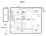
- FIG. 2 is a circuit block diagram of the power conversion apparatus 100 and its surroundings.
- the high-voltage power supply circuit unit 101 (HV Power Supply) is a power supply unit that converts power supplied from the battery 280 to the power conversion device 100 and supplies power to the gate drive circuit unit 106 (Gate Driver).
- the control unit 103 performs PWM control on the gate drive circuit unit 106 based on the motor angle information transmitted from the RD converter 105 and the torque command commanded from the control controller 270 via the CAN transceiver 104. It is a control part which performs control.
- the CAN transceiver 104 is a transformer unit for transmitting information to both the control device connected to the bus of the information communication line 290 and the control unit 103.
- the RD converter 105 sends an excitation signal to the motor 210, receives a SIN signal or COS signal excited in the motor 210, converts it into angle information, and transmits the digitized RDC signal to the control unit 103.
- the gate drive circuit unit 106 is a driver unit that supplies current to the motor 210 in accordance with a PWM control signal from the control unit 103.
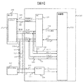
- FIG. 3 is a detailed circuit block diagram of the power conversion apparatus 100 according to the present embodiment and its surroundings.
- Excitation signal_P108 and excitation signal_N109, SIN_P118 and SIN_N119, COS_P120 and COS_N121, Hi114, and Lo115 are differential signal wirings formed in pairs.
- the resolver 211 is an angle detection unit that excites SIN_P118 and SIN_N119, COS_P120 and COS_N121 from the excitation signal_P108 and the excitation signal_N109 in the motor 210 and returns angle information to the RD converter 105.
- SIN_P 118 and SIN_N 119, COS_P 120 and COS_N 121 are directly input not only to the RD converter 105 but also to the control unit 103, and are used as redundant detection means when the RD converter 105 becomes defective.
- the relay connection units 110 to 113 are not connected during a normal operation in which the motor 210 rotates, but are connected only during a debugging mode such as soft reprogramming, internal state analysis, and internal voltage parameter change of the power conversion device 100.
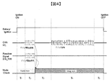
- FIG. 4 is a communication timing diagram in the debug mode.
- the debug start signal transmitted from the information control communication 107 in the period T2 is input to the control unit 103 via Hi 114 and Lo 115, and input to the control unit 103 via SIN_P 118 and SIN_N 119.
- This mode is activated only when inputs are made simultaneously with a route to be transmitted.
- SIN_118 and SIN_N119 are taken as an example, but even if Hi114 and Lo115 are connected to COS_P120 and COS_N121, they can be similarly started in the debug mode, or SIN_P118, SIN_N119 and COS_P120, COS_N121 are used. Even if they are connected simultaneously with Hi114 and Lo115, they can be similarly activated in the debug mode.
- FIG. 5 is a flowchart corresponding to a procedure manual for a user who uses the debug mode. An example of the operating environment when using the debug mode is shown in FIG.
- the user first connects the relay connection unit before turning on the power (S300), transmits a debug start signal (S302), confirms that the transmission is completed (S303), and then the user performs debugging work that requires motor driving. (S304), if YES, it is necessary to remove the relay connection unit and start debugging (S305, S306). If NO, the user can start debugging as it is. Yes (S307).
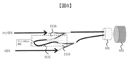
- FIG. 6 shows an embodiment relating to the connection of the relay connection unit 113.
- the connector terminal portion 402 is a connection portion that is provided on the outer surface of the power conversion apparatus 100 and into which a harness connector 401 including a wire that connects to the outside is inserted.
- the relay connection unit 113A and the relay connection unit 113B are terminals provided for relay connection between the SIN_P 118 and the Hi 114, and are connected to the relay line 113C to establish a connection between the SIN_P 118 and the Hi 114.
- the user can connect one end and the other end of the plurality of signal lines of the harness connector 401 outside the power conversion device 100, and use the debug mode without having to disassemble and use the power conversion device 100. Can do.
- the relay connection unit 113 is taken as an example, but the same configuration can be applied to the relay connection units 110 to 112.
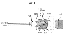
- FIG. 7 shows another embodiment relating to the connection of the relay connection unit 113.
- the relay connector 113D is an example of connection of the relay connection unit 113.
- the connector pin 113G and the connector pin 113H are members for connecting the harness connector 401 and the connector terminal portion 402 when the harness connector 401 is inserted.
- the switch 113F can connect the wiring 113K and the wiring 113J when turned on, and can disconnect the wiring 113K and the wiring 113J when turned off.
- the switch 113F is turned on, the SIN_P 118 and the Hi 114 can be relay-connected via the wiring 113K and the wiring 113J.
- the switch 113F is turned on and used, and in the process of S305, the switch 113F is turned off and used, thereby enabling debugging.
- relay connector 113D as shown in FIG. 7 as an intermediate connection means, it is easy to use the debug mode without special measures for the connector terminal portion 402, the harness connector 401, and the wiring that are usually used by the user. Can be launched.
- the operation can be performed by starting the debug mode. If the switch 113F is turned off during the subsequent debugging, the debugging can be performed while the resolver 211 (the motor 210) is driven. It can be used without adverse effects.
- the relay connection unit 113 is taken as an example, but the same configuration can be applied to the relay connection units 110 to 112.
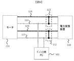
- FIG. 8 is a block diagram showing the equipment environment during the debugging work described above with reference to FIG.
- the debugging PC 500 is connected to the Hi 114 and the Low 115, and can transmit a debugging start signal to the power conversion apparatus 100 and monitor the transmission result.
- the user can use the debug mode by connecting the relay connection unit 112 or the relay connection unit 113.
- debugging PC 500 can be used in place of other devices connected by a bus such as the controller 270.
- the debug mode When the debug mode is activated only by the debug start signal flowing through the information communication lines 114 and 115, the security is impaired. However, the user can easily activate the debug mode with high security simply by inserting the relay connection units 110 to 113. it can.
- DESCRIPTION OF SYMBOLS 100 Power converter device 101 ... High voltage power supply circuit part, 102 ... Low voltage power supply circuit part, 103 ... Control part, 104 ... CAN transceiver, 105 ... RD converter, 106 ... Gate drive circuit part, 107 ... Information control communication, 108 ... excitation signal_P, 109 ... excitation signal_N, 110 ... relay connection, 111 ... relay connection, 112 ... relay connection, 113 ... relay connection, 113A ... relay connection, 113B ... relay connection, 113C ... Relay wire, 113D ... Relay connector, 113F ... Switch, 113G ... Connector pin, 113H ... Connector pin, 113J ...
Landscapes
- Engineering & Computer Science (AREA)
- Power Engineering (AREA)
- Theoretical Computer Science (AREA)
- Life Sciences & Earth Sciences (AREA)
- Sustainable Development (AREA)
- Sustainable Energy (AREA)
- Transportation (AREA)
- Mechanical Engineering (AREA)
- General Engineering & Computer Science (AREA)
- Physics & Mathematics (AREA)
- Computer Hardware Design (AREA)
- General Physics & Mathematics (AREA)
- Mathematical Physics (AREA)
- Computer Networks & Wireless Communication (AREA)
- Signal Processing (AREA)
- Quality & Reliability (AREA)
- Electric Propulsion And Braking For Vehicles (AREA)
- Control Of Ac Motors In General (AREA)
- Inverter Devices (AREA)
- Power Steering Mechanism (AREA)
- Control Of Electric Motors In General (AREA)
Abstract
パラメータ補正等のデバックモードで起動させて使用する場合、ユーザにとって安易な環境で操作できる容易性とセキュリティ性を両立することである。 本発明に係る電力変換装置は、インバータ回路部を制御するとともに情報制御通信線と繋がる制御部と、モータのロータの回転を検出するレゾルバと前記制御部と繋ぐ配線と、を備え、前記制御部は、前記情報制御通信線及び前記配線を介して取得されるデバッグ開始信号に基づき、当該制御部のプログラムを変更するデバッグモードを起動する。
Description
本発明は、電力変換装置及びそのデバッグ方法に関する。
ハイブリッド自動車や電気自動車の普及に伴い、車両の部品の電動化及び電子化が急速に進められている。この車両部品の電子化の主な例としては、モータを駆動するための電力変換装置がある。例えば、特許文献1に示されるような電動パワーステアリング装置に係る電力変換装置は、モータの回転状態を検出するためのレゾルバの検出信号の補正処理を実行している。
ところで、電力変換装置のパラメータ補正、ソフトリプログラミング、内部状態解析など、特殊動作を行うためのデバックモードで起動させて使用する場合、ユーザにとって安易な環境で操作できる容易性が求められる。しかしながら、通常使用時には想定し得ない起動環境で構成するセキュリティ性も必要である。
本発明の課題は、パラメータ補正等のデバックモードで起動させて使用する場合、ユーザにとって安易な環境で操作できる容易性とセキュリティ性を両立することである。
本発明に係る電力変換装置は、インバータ回路部を制御するとともに情報制御通信線と繋がる制御部と、モータのロータの回転を検出するレゾルバと前記制御部と繋ぐ配線と、を備え、前記制御部は、前記情報制御通信線及び前記配線を介して取得されるデバッグ開始信号に基づき、当該制御部のプログラムを変更するデバッグモードを起動する。
また本発明に係る電力変換装置のデバッグ方法は、インバータ回路部を制御する制御部と繋がる情報制御通信線と、モータのロータの回転を検出するレゾルバと当該制御部と繋ぐための配線と、を中継接続部により接続する第1工程と、前記情報制御通信線と前記配線を介してデバッグ開始信号を当該制御部に送信する第2工程と、デバッグ完了信号を受信する第3工程と、前記中継接続部を前記情報制御通信線又は前記配線から電気的に遮断させる第4工程と、前記情報制御通信線を介して前記モータの駆動に関するデバッグ信号を前記制御部に送信する第5工程(S306)と、を備える。
本発明により、パラメータ補正等のデバックモードで起動させて使用する際の容易性とセキュリティ性を両立することができる。
以下、図面を用いて本発明の実施例を説明する。
図1は、HEV200のシステムを説示するシステム構成図である。
HEV200は、エンジン230や電力変換装置100を動力としてモータ210を回転させることで走行する自動車である。
電力変換装置100は、バッテリ280から供給される電力を変換してモータ210に供給し、制御コントローラ270から受けるトルク指令に従ってモータ210を制御する。モータ210は、エンジン230または電力変換装置100を動力として回転し、HEV200を走行させる。
動力分割機構220は、モータ210を回転させる際、エンジン230を動力として使用する場合にはエンジン230とモータ210を接続し、エンジン230を動力として使用しない場合はエンジン230とモータ210を切り離す機構である。
エンジン230は、エンジンECU240から制御されて、モータ210を回転させる。エンジンECU240は、制御コントローラ270から指令を受け、エンジン230を制御する。
EPS用ECU250は、制御コントローラ270から指令を受け、電動ステアリングを制御する。ブレーキECU260は、制御コントローラ270から指令を受け、ブレーキを制御する。
制御コントローラ270は、電力変換装置100、モータ210、エンジンECU240、EPS用ECU250、ブレーキECU260、バッテリ280と情報通信ライン290で双方に情報を伝達するHEV200の主となる制御コントローラである。
バッテリ280は、モータ210の動力となる電力を電力変換装置100を経て供給する電源である。
図2は、電力変換装置100とその周辺の回路ブロック図である。
高電圧電源回路部101(HV Power Supply)は、バッテリ280から電力変換装置100に供給される電力を変換し、ゲート駆動回路部106(Gate Driver)に電力供給する電源部である。
低電圧電源回路部102(LV Power Supply)、HEV200の低電圧電源(Low Volt Battery)から電力変換装置100に供給される電力を変換し、制御部103、CANトランシーバー104(CAN Transceiver)、RDコンバータ105(R/D Converter)に電力供給する電源部である。
制御部103は、RDコンバータ105から伝達されるモータ角度情報と、制御コントローラ270からCANトランシーバー104を経由して指令されるトルク指令とを元にゲート駆動回路部106に対してPWM制御を行い電流制御を行う制御部である。
CANトランシーバー104は、情報通信ライン290のバスに繋がる制御機器と制御部103と双方に情報を伝達するためのトランス部である。
RDコンバータ105はモータ210に励磁信号を送り、モータ210内で励磁されたSIN信号やCOS信号を受信して角度情報に変換し、デジタル化されたRDC信号を制御部103に伝達する。
ゲート駆動回路部106は、制御部103からのPWM制御信号により、モータ210に電流を流すドライバ部である。
図3は、本実施形態に係る電力変換装置100とその周辺の詳細回路ブロック図である。
励磁信号_P108と励磁信号_N109、SIN_P118とSIN_N119、COS_P120とCOS_N121、Hi114、Lo115はそれぞれ対になって成り立つ差動信号配線である。
レゾルバ211は、モータ210内で励磁信号_P108と励磁信号_N109からSIN_P118とSIN_N119、COS_P120とCOS_N121を励磁してRDコンバータ105に角度情報を返す角度検知部である。
SIN_P118とSIN_N119、COS_P120とCOS_N121はRDコンバータ105だけでなく、制御部103にも直接入力され、RDコンバータ105が不良となった場合の冗長検知手段として使われる。
中継接続部110ないし113は、モータ210が回転する通常動作時には接続されないが、電力変換装置100のソフトリプログラミング、内部状態解析、内部電圧パラメータ変更などのデバックモード時にのみ接続される。
図4は、デバックモード時の通信タイミング図である。
図3に示されるデバックモードは、情報制御通信107からT2期間で発信されるデバック開始信号が、Hi114とLo115を経て制御部103に入力される経路と、SIN_P118とSIN_N119を経て制御部103に入力される経路とで同時に入力される場合にのみ起動するモードである。
なお、ここではSIN_118とSIN_N119を例に挙げたが、Hi114とLo115がCOS_P120とCOS_N121と接続されて用いられても同様にデバックモードで起動することができるし、或いは、SIN_P118、SIN_N119とCOS_P120、COS_N121とがHi114、Lo115と同時に接続されても同様にデバックモードで起動することができる。
図5は、デバックモードを利用するユーザのための手順マニュアルに対応するフローチャートである。なお、デバックモードを利用する際の操作環境例については図8で示す。
ユーザは、まず電源投入前に中継接続部を接続し(S300)、デバック開始信号を送信して(S302)、送信が完了したことを確認したら(S303)、ユーザはモータ駆動が必要なデバック作業を行うか否かを判断し(S304)、YESであれば、中継接続部を外してデバックを開始する必要があり(S305、S306)、Noであれば、ユーザはそのままデバックを開始することができる(S307)。
図6は、中継接続部113の接続に関する実施形態である。
コネクタ端子部402は電力変換装置100の外面に設けられ、外部と接続する線を備えるハーネスコネクタ401が挿入される接続部である。
中継接続部113Aと中継接続部113Bは、SIN_P118とHi114を中継接続するために設けられた端子であり、中継線113Cと接続されることで、SIN_P118とHi114の接続を確立させる。
これにより、電力変換装置100の外側で、ユーザはハーネスコネクタ401の複数の信号線の一端と他端を接続することができ、電力変換装置100を分解して使う必要なくデバックモードを使用することができる。
なお図6中では、中継接続部113を例にあげているが、中継接続部110ないし112も同様の構成を適用できる。
図7は、中継接続部113の接続に関する他の実施形態である。中継コネクタ113Dは、中継接続部113の接続の一例である。
コネクタピン113G及びコネクタピン113Hは、ハーネスコネクタ401が挿入されることでハーネスコネクタ401とコネクタ端子部402と接続させるための部材である。
スイッチ113Fは、オンされると配線113Kと配線113Jを接続し、オフされると配線113Kと配線113Jを切り離すことができる。スイッチ113Fがオンされると、配線113Kと配線113Jを経由してSIN_P118とHi114を中継接続することができる。図5で前述したS300の工程では、スイッチ113Fをオンして使用し、S305の工程では、スイッチ113Fをオフして使用することで、デバック作業を可能にする。
中継接続する手段として、図7のような中継コネクタ113Dを間に入れて使うことで、普段ユーザが使うコネクタ端子部402とハーネスコネクタ401およびその配線に特別な工夫を施すことなく手軽にデバックモードを起動することができる。
また、スイッチ113Fがオンされているときは、デバックモード起動で動作させることができ、その後のデバック中にスイッチ113Fをオフして使用すれば、レゾルバ211(モータ210)を駆動しながら行うデバックに悪影響を及ぼすことなく使用することができる。
なお図7中では、中継接続部113を例にあげているが、中継接続部110ないし112も同様の構成を適用できる。
図8は、図5で前述したデバック作業時の設備環境を示したブロック図である。
デバック用PC500は、Hi114とLow115と接続されており、デバック開始信号を電力変換装置100に送信し、送信結果をモニタすることができる。ユーザは中継接続部112や中継接続部113を接続してデバックモードを使用することができる。
なお、デバック用PC500は、制御コントローラ270などバスで繋がっている他機器を代用して使用することも可能である。
電力変換装置100のパラメータ補正、ソフトリプロ、内部状態解析など、特殊動作を行うためのデバックモードで起動させて使用する場合、ユーザにとって安易な環境で操作できる容易性が求められるが、通常使用時には想定し得ない起動環境で構成するセキュリティ性も必要である。
図3に示されたように、情報制御通信線に対応するHi114及びLo115とレゾルバ211と制御部103を繋ぐ配線に対応するSIN_P118、SIN_N119、COS_P120、COS_N121を中継接続するという環境で使用すると、情報通信線に対応するHi114及びLo115に流れるデバック開始信号がレゾルバ211と制御部103を繋ぐSIN_P118、SIN_N119、COS_P120、COS_N121をも経由することになり、これらのデバック開始信号が同時に制御部103に入力されたときのみデバックモードが起動する。
情報通信線114、115に流れるデバック開始信号だけでデバックモードが起動するとセキュリティ性が損なわれるが、中継接続部110ないし113を入れるだけで容易にかつ高いセキュリティ性でユーザはデバックモード起動することができる。
100…電力変換装置、101…高電圧電源回路部、102…低電圧電源回路部、103…制御部、104…CANトランシーバー、105…RDコンバータ、106…ゲート駆動回路部、107…情報制御通信、108…励磁信号_P、109…励磁信号_N、110…中継接続部、111…中継接続部、112…中継接続部、113…中継接続部、113A…中継接続部、113B…中継接続部、113C…中継線、113D…中継コネクタ、113F…スイッチ、113G…コネクタピン、113H…コネクタピン、113J…配線、113K…配線、114…Hi、115…Lo、116…シリアル通信、117…RDC信号、118…SIN_P、119…SIN_N、120…COS_P、121…COS_N、200…HEV、210…モータ、211…レゾルバ、220…動力分割機構、230…エンジン、240…エンジンECU、250…EPS用ECU、260…ブレーキECU、270…制御コントローラ、280…バッテリ、290…情報通信ライン、401…ハーネスコネクタ、402…コネクタ端子部、500…デバック用PC
Claims (5)
- インバータ回路部を制御するとともに情報制御通信線と繋がる制御部と、
モータのロータの回転を検出するレゾルバと前記制御部と繋ぐ配線と、を備え、
前記制御部は、前記情報制御通信線及び前記配線を介して取得されるデバッグ開始信号に基づき、
当該制御部のプログラムを変更するデバッグモードを起動する電力変換装置。 - 請求項1に記載の電力変換装置であって、
前記制御部を収納するハウジングと、
前記ハウジングの一部に設けられかつ前記情報制御通信線を介して前記制御部と接続される第1コネクタと、
前記ハウジングの収納空間の外側に配置される複数の信号線と繋がるとともに前記第1コネクタと接続される第2コネクタと、備え、
前記配線は、一端と他端が前記複数の信号線のいずれか2つとそれぞれ接続される電力変換装置。 - 請求項1に記載の電力変換装置であって、
前記制御部を収納するハウジングと、
前記ハウジングの一部に設けられかつ前記情報制御通信線を介して前記制御部と接続される第1コネクタと、
前記ハウジングの収納空間の外側に配置される複数の信号線と繋がる第2コネクタと前記第1コネクタとの間に接続される中継コネクタと、を備え、
前記中継コネクタは、前記複数の信号線に接続されるとともに前記第1コネクタに接続される複数の端子を有し、
前記配線は、一端と他端が前記複数の端子のいずれか2つとそれぞれ接続される電力変換装置。 - 請求項3に記載の電力変換装置であって、
前記配線に接続されかつ信号を遮断及び導通させるスイッチ部を有する電力変換装置。 - インバータ回路部を制御する制御部と繋がる情報制御通信線と、モータのロータの回転を検出するレゾルバと当該制御部と繋ぐための配線と、を中継接続部により接続する第1工程と、
前記情報制御通信線と前記配線を介してデバッグ開始信号を当該制御部に送信する第2工程と、
デバッグ完了信号を受信する第3工程と、
前記中継接続部を前記情報制御通信線又は前記配線から電気的に遮断させる第4工程と、
前記情報制御通信線を介して前記モータの駆動に関するデバッグ信号を前記制御部に送信する第5工程と、を備える電力変換装置のデバッグ方法。
Priority Applications (3)
| Application Number | Priority Date | Filing Date | Title |
|---|---|---|---|
| US16/620,037 US20200094681A1 (en) | 2017-06-07 | 2018-04-20 | Electric Power Conversion Device and Method for Debugging the Same |
| DE112018002370.2T DE112018002370T5 (de) | 2017-06-07 | 2018-04-20 | Vorrichtung für die Umsetzung elektrischer Leistung und Verfahren zur Behebung ihrer Fehler |
| JP2019523385A JP6838245B2 (ja) | 2017-06-07 | 2018-04-20 | 電力変換装置及びそのデバッグ方法 |
Applications Claiming Priority (2)
| Application Number | Priority Date | Filing Date | Title |
|---|---|---|---|
| JP2017-112201 | 2017-06-07 | ||
| JP2017112201 | 2017-06-07 |
Publications (1)
| Publication Number | Publication Date |
|---|---|
| WO2018225402A1 true WO2018225402A1 (ja) | 2018-12-13 |
Family
ID=64566858
Family Applications (1)
| Application Number | Title | Priority Date | Filing Date |
|---|---|---|---|
| PCT/JP2018/016239 Ceased WO2018225402A1 (ja) | 2017-06-07 | 2018-04-20 | 電力変換装置及びそのデバッグ方法 |
Country Status (4)
| Country | Link |
|---|---|
| US (1) | US20200094681A1 (ja) |
| JP (1) | JP6838245B2 (ja) |
| DE (1) | DE112018002370T5 (ja) |
| WO (1) | WO2018225402A1 (ja) |
Citations (3)
| Publication number | Priority date | Publication date | Assignee | Title |
|---|---|---|---|---|
| JP2008090390A (ja) * | 2006-09-29 | 2008-04-17 | Matsushita Electric Ind Co Ltd | マイコンデバッグシステムおよびマイクロコンピュータ |
| JP2011097679A (ja) * | 2009-10-27 | 2011-05-12 | Jtekt Corp | 回転角検出装置の製造方法、回転角検出装置、モータ制御装置及び電動パワーステアリング装置 |
| JP2012244637A (ja) * | 2011-05-13 | 2012-12-10 | Denso Corp | モータ駆動装置 |
-
2018
- 2018-04-20 DE DE112018002370.2T patent/DE112018002370T5/de not_active Withdrawn
- 2018-04-20 WO PCT/JP2018/016239 patent/WO2018225402A1/ja not_active Ceased
- 2018-04-20 US US16/620,037 patent/US20200094681A1/en not_active Abandoned
- 2018-04-20 JP JP2019523385A patent/JP6838245B2/ja not_active Expired - Fee Related
Patent Citations (3)
| Publication number | Priority date | Publication date | Assignee | Title |
|---|---|---|---|---|
| JP2008090390A (ja) * | 2006-09-29 | 2008-04-17 | Matsushita Electric Ind Co Ltd | マイコンデバッグシステムおよびマイクロコンピュータ |
| JP2011097679A (ja) * | 2009-10-27 | 2011-05-12 | Jtekt Corp | 回転角検出装置の製造方法、回転角検出装置、モータ制御装置及び電動パワーステアリング装置 |
| JP2012244637A (ja) * | 2011-05-13 | 2012-12-10 | Denso Corp | モータ駆動装置 |
Also Published As
| Publication number | Publication date |
|---|---|
| JPWO2018225402A1 (ja) | 2020-03-19 |
| JP6838245B2 (ja) | 2021-03-03 |
| US20200094681A1 (en) | 2020-03-26 |
| DE112018002370T5 (de) | 2020-01-23 |
Similar Documents
| Publication | Publication Date | Title |
|---|---|---|
| US10336365B2 (en) | Electromechanical power steering system | |
| US12325471B2 (en) | Steering apparatus | |
| CN102917940B (zh) | 控制系统及电动动力转向控制装置 | |
| JP4939355B2 (ja) | 車載空気調和機用インバータシステム | |
| US11807316B2 (en) | Power steering apparatus | |
| CN104731082A (zh) | 一种接口转换装置及车载诊断系统 | |
| WO2017159277A1 (ja) | 制御システム | |
| CN111162697A (zh) | 马达控制装置 | |
| JP5385240B2 (ja) | 電動車の電気系統制御システム | |
| JP4368031B2 (ja) | 伝達比可変操舵装置 | |
| JP6838245B2 (ja) | 電力変換装置及びそのデバッグ方法 | |
| CN111771130B (zh) | 安全开关输入诊断装置以及作业机械 | |
| CN105539429A (zh) | 一种泊车辅助系统 | |
| CN113391624B (zh) | 一种车辆动力域控制系统及方法、存储介质、计算机设备 | |
| EP3187394B1 (en) | Power-assisted steering system and mobile inspection device | |
| US10594248B2 (en) | Adaptive steering torque control | |
| JP6296403B2 (ja) | インバータユニットおよび電動車両 | |
| JP5949103B2 (ja) | インバータユニットおよび電動車両 | |
| JP2021035814A (ja) | 車両用制御装置 | |
| JP4715856B2 (ja) | 電源システムの故障判定方法 | |
| JP3886950B2 (ja) | 車両の操舵制御装置 | |
| JP3346627B2 (ja) | 回転座席制御方法 | |
| WO2017122709A1 (ja) | シフトバイワイヤ制御装置、電源システム、シフトバイワイヤ制御方法 | |
| JP4670769B2 (ja) | 多相モータの駆動システム | |
| JP2011239561A (ja) | 充電システム |
Legal Events
| Date | Code | Title | Description |
|---|---|---|---|
| 121 | Ep: the epo has been informed by wipo that ep was designated in this application |
Ref document number: 18814355 Country of ref document: EP Kind code of ref document: A1 |
|
| ENP | Entry into the national phase |
Ref document number: 2019523385 Country of ref document: JP Kind code of ref document: A |
|
| 122 | Ep: pct application non-entry in european phase |
Ref document number: 18814355 Country of ref document: EP Kind code of ref document: A1 |