WO2018221076A1 - 燃料噴射弁及びエンジンシステム - Google Patents
燃料噴射弁及びエンジンシステム Download PDFInfo
- Publication number
- WO2018221076A1 WO2018221076A1 PCT/JP2018/016524 JP2018016524W WO2018221076A1 WO 2018221076 A1 WO2018221076 A1 WO 2018221076A1 JP 2018016524 W JP2018016524 W JP 2018016524W WO 2018221076 A1 WO2018221076 A1 WO 2018221076A1
- Authority
- WO
- WIPO (PCT)
- Prior art keywords
- fuel injection
- injection hole
- fuel
- hole group
- valve
- Prior art date
- Legal status (The legal status is an assumption and is not a legal conclusion. Google has not performed a legal analysis and makes no representation as to the accuracy of the status listed.)
- Ceased
Links
Images




Classifications
-
- F—MECHANICAL ENGINEERING; LIGHTING; HEATING; WEAPONS; BLASTING
- F02—COMBUSTION ENGINES; HOT-GAS OR COMBUSTION-PRODUCT ENGINE PLANTS
- F02B—INTERNAL-COMBUSTION PISTON ENGINES; COMBUSTION ENGINES IN GENERAL
- F02B31/00—Modifying induction systems for imparting a rotation to the charge in the cylinder
- F02B31/04—Modifying induction systems for imparting a rotation to the charge in the cylinder by means within the induction channel, e.g. deflectors
-
- F—MECHANICAL ENGINEERING; LIGHTING; HEATING; WEAPONS; BLASTING
- F02—COMBUSTION ENGINES; HOT-GAS OR COMBUSTION-PRODUCT ENGINE PLANTS
- F02B—INTERNAL-COMBUSTION PISTON ENGINES; COMBUSTION ENGINES IN GENERAL
- F02B23/00—Other engines characterised by special shape or construction of combustion chambers to improve operation
- F02B23/08—Other engines characterised by special shape or construction of combustion chambers to improve operation with positive ignition
- F02B23/10—Other engines characterised by special shape or construction of combustion chambers to improve operation with positive ignition with separate admission of air and fuel into cylinder
-
- F—MECHANICAL ENGINEERING; LIGHTING; HEATING; WEAPONS; BLASTING
- F02—COMBUSTION ENGINES; HOT-GAS OR COMBUSTION-PRODUCT ENGINE PLANTS
- F02B—INTERNAL-COMBUSTION PISTON ENGINES; COMBUSTION ENGINES IN GENERAL
- F02B31/00—Modifying induction systems for imparting a rotation to the charge in the cylinder
- F02B31/04—Modifying induction systems for imparting a rotation to the charge in the cylinder by means within the induction channel, e.g. deflectors
- F02B31/06—Movable means, e.g. butterfly valves
-
- F—MECHANICAL ENGINEERING; LIGHTING; HEATING; WEAPONS; BLASTING
- F02—COMBUSTION ENGINES; HOT-GAS OR COMBUSTION-PRODUCT ENGINE PLANTS
- F02D—CONTROLLING COMBUSTION ENGINES
- F02D41/00—Electrical control of supply of combustible mixture or its constituents
- F02D41/02—Circuit arrangements for generating control signals
- F02D41/04—Introducing corrections for particular operating conditions
-
- F—MECHANICAL ENGINEERING; LIGHTING; HEATING; WEAPONS; BLASTING
- F02—COMBUSTION ENGINES; HOT-GAS OR COMBUSTION-PRODUCT ENGINE PLANTS
- F02D—CONTROLLING COMBUSTION ENGINES
- F02D43/00—Conjoint electrical control of two or more functions, e.g. ignition, fuel-air mixture, recirculation, supercharging or exhaust-gas treatment
-
- F—MECHANICAL ENGINEERING; LIGHTING; HEATING; WEAPONS; BLASTING
- F02—COMBUSTION ENGINES; HOT-GAS OR COMBUSTION-PRODUCT ENGINE PLANTS
- F02D—CONTROLLING COMBUSTION ENGINES
- F02D45/00—Electrical control not provided for in groups F02D41/00 - F02D43/00
-
- F—MECHANICAL ENGINEERING; LIGHTING; HEATING; WEAPONS; BLASTING
- F02—COMBUSTION ENGINES; HOT-GAS OR COMBUSTION-PRODUCT ENGINE PLANTS
- F02F—CYLINDERS, PISTONS OR CASINGS, FOR COMBUSTION ENGINES; ARRANGEMENTS OF SEALINGS IN COMBUSTION ENGINES
- F02F1/00—Cylinders; Cylinder heads
- F02F1/24—Cylinder heads
- F02F1/42—Shape or arrangement of intake or exhaust channels in cylinder heads
-
- F—MECHANICAL ENGINEERING; LIGHTING; HEATING; WEAPONS; BLASTING
- F02—COMBUSTION ENGINES; HOT-GAS OR COMBUSTION-PRODUCT ENGINE PLANTS
- F02M—SUPPLYING COMBUSTION ENGINES IN GENERAL WITH COMBUSTIBLE MIXTURES OR CONSTITUENTS THEREOF
- F02M61/00—Fuel-injectors not provided for in groups F02M39/00 - F02M57/00 or F02M67/00
- F02M61/14—Arrangements of injectors with respect to engines; Mounting of injectors
-
- F—MECHANICAL ENGINEERING; LIGHTING; HEATING; WEAPONS; BLASTING
- F02—COMBUSTION ENGINES; HOT-GAS OR COMBUSTION-PRODUCT ENGINE PLANTS
- F02M—SUPPLYING COMBUSTION ENGINES IN GENERAL WITH COMBUSTIBLE MIXTURES OR CONSTITUENTS THEREOF
- F02M61/00—Fuel-injectors not provided for in groups F02M39/00 - F02M57/00 or F02M67/00
- F02M61/16—Details not provided for in, or of interest apart from, the apparatus of groups F02M61/02 - F02M61/14
- F02M61/18—Injection nozzles, e.g. having valve seats; Details of valve member seated ends, not otherwise provided for
-
- Y—GENERAL TAGGING OF NEW TECHNOLOGICAL DEVELOPMENTS; GENERAL TAGGING OF CROSS-SECTIONAL TECHNOLOGIES SPANNING OVER SEVERAL SECTIONS OF THE IPC; TECHNICAL SUBJECTS COVERED BY FORMER USPC CROSS-REFERENCE ART COLLECTIONS [XRACs] AND DIGESTS
- Y02—TECHNOLOGIES OR APPLICATIONS FOR MITIGATION OR ADAPTATION AGAINST CLIMATE CHANGE
- Y02T—CLIMATE CHANGE MITIGATION TECHNOLOGIES RELATED TO TRANSPORTATION
- Y02T10/00—Road transport of goods or passengers
- Y02T10/10—Internal combustion engine [ICE] based vehicles
- Y02T10/12—Improving ICE efficiencies
Definitions
- the present invention relates to a fuel injection valve used in an internal combustion engine such as a gasoline engine, and an engine system.
- Patent Document 2 describes a technique for optimizing spraying in a low rotation region where air flow is small.
- Patent Document 2 optimizes spraying in a low rotation region where air flow is small.
- the technique disclosed in Patent Document 2 there is no description about the case where the high-speed flow is unevenly distributed when the tumble control valve is closed, and it has been difficult to form a highly homogeneous gas mixture and reduce wall adhesion.
- an object of the present invention is to provide a fuel injection valve capable of forming highly homogeneous fuel spray in the combustion chamber and reducing wall surface adhesion.
- the fuel injection valve of the present invention is a fuel injection valve that injects fuel directly into a combustion chamber.
- the center axis of the fuel injection hole is directed toward the tip of the spark plug from the center of the upper surface of the piston.
- a first injection hole group, and a second injection hole group in which a central axis of the fuel injection hole is directed toward the center of the upper surface of the piston with respect to the spark plug tip, and the fuel injection hole of the first injection hole group Is configured to be larger than the flow rate of the spray injected from the fuel injection holes of the second injection hole group and to reduce the penetration.
- 1 is a sectional view of an internal combustion engine according to a first embodiment of the present invention (when a tumble control valve is opened). 1 is a sectional view of an internal combustion engine according to a first embodiment of the present invention (when a tumble control valve is closed). It is the figure which showed the fuel injection of the internal combustion engine which concerns on 1st Example of this invention. 1 is a view showing an air-fuel mixture immediately after fuel injection of an internal combustion engine according to a first embodiment of the present invention.
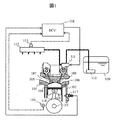
- FIG. 1 is a diagram showing an outline of the configuration of a direct injection engine. The basic operation of the direct injection engine will be described with reference to FIG.
- a combustion chamber 104 is formed by a cylinder head 101, a cylinder block 102, and a piston 103 inserted into the cylinder block 102, and an intake pipe 105 and an exhaust pipe 106 are branched into two toward the fuel chamber 104. It is connected.
- An intake valve 107 is provided at the opening of the intake pipe 105, and an exhaust valve 108 is provided at the opening of the exhaust pipe 106, and operates so as to open and close by a cam operation method.
- the piston 103 is connected to the crankshaft 115 via a connecting rod 114, and the engine speed can be detected by the crank angle sensor 116.
- the value of the rotational speed is sent to an ECU (Engine Control Unit) 118.
- a cell motor (not shown) is connected to the crankshaft 115, and when starting the engine, the crankshaft 115 can be rotated and started by the cell motor.
- the cylinder block 102 is provided with a water temperature sensor 117 and can detect the temperature of engine coolant (not shown). The temperature of the engine cooling water is sent to the ECU 118.
- FIG. 1 shows only one cylinder, but a collector (not shown) is provided upstream of the intake pipe 105 to distribute air to each cylinder.
- An air flow sensor and a throttle valve are provided upstream of the collector, and the amount of air taken into the fuel chamber 104 can be adjusted by the opening of the throttle valve.
- Fuel is stored in the fuel tank 109 and sent to the high-pressure fuel pump 111 by the feed pump 110.
- the feed pump 110 boosts the fuel to about 0.3 MPa and sends it to the high-pressure fuel pump 111.
- the fuel boosted by the high pressure fuel pump 111 is sent to the common rail 112.
- the high pressure fuel pump 111 boosts the fuel to about 30 MPa and sends it to the common rail 112.
- a fuel pressure sensor 113 is provided on the common rail 112 to detect fuel pressure (fuel pressure). The value of the fuel pressure is sent to the ECU 118.
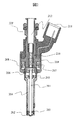
- FIG. 2 is a diagram showing an example of an electromagnetic fuel injection valve as an example of the fuel injection valve of the present embodiment.
- the basic operation of the injection device will be described with reference to FIG.
- the fuel is supplied from the fuel supply port 212 and supplied to the inside of the fuel injection valve.
- the electromagnetic fuel injection valve 119 shown in FIG. 2 is a normally closed electromagnetic drive type, and when the coil 208 is not energized, the valve body 201 is urged by the spring 210 and the nozzle body 204 is welded or the like. The fuel is sealed by being pressed against the joined sheet member 202.
- a plurality of fuel injection holes 301 are formed on the downstream side of the seat portion of the seat member 202 on which the valve body seat portion of the valve body 201 is seated. At this time, in the in-cylinder fuel injection valve, the supplied fuel pressure is in the range of about 1 MPa to 50 MPa.
- valve body seat portion of the valve body 201 is separated from the seat portion of the seat member 202, and a gap is generated between them.
- high-pressure fuel is injected through the fuel injection hole formed in the seat member 202.
- the energy given as the fuel pressure is converted into kinetic energy and injected into the fuel injection hole vacated at the lower end of the fuel injection valve.
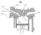
- FIG. 3 is an enlarged view of the inside of the combustion chamber having the same cross section as FIG.
- a fuel injection valve 119 is provided on the radial side surface of the cylinder.
- the spark plug 120 is provided in the vicinity of the exhaust pipe 106 at the upper surface in the axial direction of the cylinder.
- a partition wall 121 is attached to the intake port 105.
- the partition wall 121 is configured to partition the passage of the intake port 105 vertically in the cylinder axis direction. That is, the air flow path of the intake port 105 is divided into an upper flow path and a lower flow path by the partition wall 121.
- the tumble control valve 122 is disposed on the upstream side of the partition wall 121 and is controlled so that a part of the flow path of the intake port 105 is opened and closed. Specifically, the tumble control valve 122 opens and closes the lower flow path of the intake port 105 formed by the partition wall 121.
- the ECU 118 can monitor the signal of the sensor and control the operation of devices such as the first fuel injection valve 119, the spark plug 120, the high-pressure fuel pump 111, and the tumble control valve 122.
- devices such as the first fuel injection valve 119, the spark plug 120, the high-pressure fuel pump 111, and the tumble control valve 122.
- the ROM of the ECU 118 set values of various devices corresponding to commonly used engine speed, water temperature, and air-fuel ratio are recorded as map data.
- the tumble control valve 122 is in an open state, and a flow 123 passing through the upper flow path of the partition wall 121 and a flow 124 passing through the lower flow path of the partition wall are formed in the intake stroke.
- FIG. 4 is a view showing a state in which the tumble control valve 122 is closed in the same cross section as FIG.
- a flow 125 passing through the upper flow path of the partition wall 121 provided to the intake port 105 forms a strong flow in the combustion chamber.
- the flow 126 in the lower flow path becomes weaker than the flow 125 by being blocked by the partition wall 121.
- the central axis 127 of the valve is extended to the upper part of the piston and the region in the combustion chamber is divided into the region 128 and the region 129, a strong flow is formed in the region 128 and weak in the region 129 in the intake stroke. A flow is formed.
- FIG. 5 is a schematic view when fuel is injected from the fuel injection valve 119 while the piston 103 is descending in the same cross section as FIG.
- the fuel spray 130 is injected from the injector 119 into the region 128 where the flow is strong, and the fuel spray 131 is injected into the region 129 where the flow is weak. That is, in the injector 119 that directly injects fuel into the combustion chamber 104, the first injection hole group 140 in which the center shaft 305 of the fuel injection hole 301 is directed to the spark plug tip 120a side from the piston upper surface center 103a, and the fuel There is a second injection hole group 141 in which the central axis of the injection hole is directed to the piston upper surface center 103a side from the spark plug tip 120a.
- the fuel spray 130 is injected from the fuel injection holes (301a, 301b, 301c) of the first injection hole group 140, and the fuel spray 131 is injected from the fuel injection holes (301d, 301e, 301f) of the second injection hole group 141.
- the fuel spray 130 indicates fuel spray from one of the fuel injection holes (301a, 301b, 301c) of the first injection hole group 140.
- the fuel spray 131 indicates the second injection hole group 141.
- the fuel spray from one of the fuel injection holes (301d, 301e, 301f) is shown.
- Reference numeral 132 denotes the spray direction of the central axis of the fuel spray 130, which is substantially the same direction as the central axis of the fuel injection holes (301 a, 301 b, 301 c) of the first injection hole group 140.
- 133 indicates the spray direction of the central axis of the fuel spray 131, which is substantially the same as the central axis of the fuel injection holes (301d, 301e, 301f) of the second injection hole group 141.
- the fuel injection holes (301a, 301b, 301c) of the first injection hole group 140 are the fuel injection holes of the second injection hole group 141 when the piston 103 is at the bottom dead center.
- (301d, 301e, 301f) is configured to be larger than the flow rate of the spray injected and to decrease the penetration. That is, in the region 128 having a strong flow, the fuel injection flow rate of the fuel injection holes (301a, 301b, 301c) of the first injection hole group 140 is larger than that of the spray to the region 129 and the penetration force of the spray is high. (Penetration) should be reduced.
- the fuel spray 131 in the second injection hole group 141 has a smaller flow rate than the spray to the region 128 due to the fuel injection holes (301d, 301e, 301f), and the dispersion by the flow. Therefore, the penetration force (penetration) of the spray is made stronger than that of the fuel spray 130. Thereby, the fuel can be diffused by the momentum of the fuel spray 131.
- the spray injected from the injection holes of the first injection hole group is larger than the flow rate of the spray injected from the injection holes of the second injection hole group, and the penetration is reduced, so that the flow is reduced.
- the strong region 128 and the weakly flowing region 129 it is possible to realize spraying with excellent dispersibility and a small amount of adhesion.
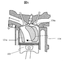
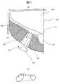
- FIG. 6 is a diagram showing a region where fuel exists immediately after fuel injection. Since the fuel spray 130 has a large flow rate, the fuel distribution 130a is formed in a wide range, and the fuel spray 131 forms the fuel distribution 131a in a region where the flow is weak. At this time, the fuel distribution moves in the forward tumble direction by the tumble 134 formed in the cylinder in the forward tumble direction (clockwise direction in the figure).
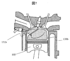
- FIG. 7 is a view showing the fuel distribution in the fuel chamber during the compression stroke in which the piston 103 operates in the upward direction (initial stage of the compression stroke).
- the fuel distribution 130a and the fuel distribution 131a move in the forward tumble direction to form a fuel distribution 130b and a fuel distribution 131b, respectively.
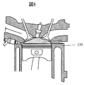
- FIG. 8 shows the fuel distribution in the latter half of the compression stroke.
- the fuel distribution 130b and the fuel distribution 131b form a homogeneous mixture 135 in the fuel chamber.
- the fuel injection valve according to the present embodiment includes the first injection hole group 140 in which the central axis 303 of the fuel injection hole 301 is directed toward the spark plug tip portion 120a with respect to the piston upper surface center 103a, and the fuel A central axis 303 of the injection hole 301 has a second injection hole group 141 that is directed to the piston upper surface center 103a side of the spark plug tip part 120a.
- the fuel injection holes (301a, 301b, 301c) of the first injection hole group 140 are larger than the flow rate of the spray injected from the fuel injection holes (301d, 301e, 301f) of the second injection hole group 141, and Configured to reduce penetration.
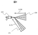
- FIG. 9 shows the fuel spray 130 injected from the fuel injection holes (301a, 301b, 301c) of the first injection hole group 140 provided to the fuel injection valve 119, and the fuel injection holes (301d) of the second injection hole group 141.
- , 301e, 301f) are schematic views of fuel spray 131 injected.
- L130 represents the penetration of the fuel spray 130 injected from the fuel injection holes (301a, 301b, 301c) of the first injection hole group 140
- L131 represents the fuel injection holes (301d, 301e, 301f) of the second injection hole group 141. Represents the penetration of the fuel spray 131 injected from the fuel.
- the spray injected from the fuel injection holes (301a, 301b, 301c) of the first injection hole group 140 is more than the flow rate of the spray injected from the fuel injection holes (301d, 301e, 301f) of the second injection hole group 141.
- the penetration L130 is configured to be larger than the penetration L131.
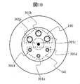
- FIG. 10 is an enlarged view of the tip of the fuel injection valve.
- the first injection hole group 140 is composed of three fuel injection holes (301a, 301b, 301c)
- the second injection hole group 141 is composed of three fuel injection holes (301d, 301e, 301f).
- This is a multi-hole fuel injection valve with injection holes.
- the number of fuel injection holes in each injection hole group (140, 141) is not limited to three.
- the fuel injection holes (301a, 301b, 301c) of the first injection hole group 140 and the fuel injection holes (301d, 301e, 301f) of the second injection hole group 141 have different hole diameters.
- the diameters of the fuel injection holes (301d, 301e, 301f) of the second injection hole group 141 are smaller than the fuel injection holes (301a, 301b, 301c) of the first injection hole group 140. Composed. Thereby, the spray injected from the fuel injection holes (301a, 301b, 301c) of the first injection hole group 140 is compared with the spray injected from the fuel injection holes (301d, 301e, 301f) of the second injection hole group 141. The flow rate can be increased.
- the minimum cross-sectional area in the direction perpendicular to the central axis 303 of the fuel injection holes (301a, 301b, 301c) of the second injection hole group 141 is the center of the fuel injection holes (301a, 301b, 301c) of the first injection hole group 140. It may be said that it is configured to be smaller than the minimum cross-sectional area in the direction perpendicular to the axis 303.
- FIG. 11 is an enlarged cross-sectional view of the tip of the fuel injection valve parallel to the injection hole shaft 303 of the fuel injection holes (301a, 301b, 301c) belonging to the first injection hole group 140 and the valve body shaft 305.
- the tip of the fuel injection valve is composed of a valve body 201, a seat member 202, a sac chamber 302, and a valve seat surface 304.
- the fuel passes through the gap between the valve body 201 and the seat member 202 and flows into the fuel injection hole (301a, 301b, 301c) through the path of the flow 311 or passes through the path of the flow 312 through the sac chamber 302. It flows into the fuel injection holes (301a, 301b, 301c).
- the fuel injection holes (301a, 301b, 301c) of the first injection hole group 140 are configured so that the cross-sectional area increases toward the outlet. As the flow path expands toward the outlet, the flow velocity in the main flow direction decreases, and the injection direction 306 at the outlet of the injection hole increases, resulting in a decrease in penetration.
- FIG. 12 is an enlarged view of the vicinity of the fuel injection valve of the fuel spray 130 injected from the first injection hole group 140 and the fuel spray 131 injected from the second injection hole group 141.
- the fuel injection holes (301a, 301b, 301c) of the first injection hole group 140 have a taper that expands toward the outlet, and the spray spreads downstream from the injection hole outlet, thereby reducing penetration. .
- the fuel injection holes (301a, 301b, 301c) of the first injection hole group 140 have a taper whose cross-sectional area increases toward the injection outlet, so that the fuel injection holes (301d, 301e) of the second injection hole group 141 , 301f), it is possible to inject the fuel spray 130 having a lower penetration than the fuel spray 131 injected from the fuel spray 131.
- the fuel injection holes (301d, 301e, 301f) of the second injection hole group 141 may have a throttle taper shape in which the cross-sectional area decreases toward the injection hole outlet.
- FIG. 13 is a diagram showing fuel injection when the tumble control valve 122 is open.
- the inflow 124 from the lower part of the partition wall 121 is generated, so that a strong downward flow is formed.
- the fuel spray injected from the fuel injection holes (301a, 301b, 301c) belonging to the first injection hole group 140 which has a low penetration force, flows downwardly against the flow and is sufficiently dispersed in the combustion chamber.
- the penetration force of the spray can be increased and the fuel can be sufficiently dispersed in the combustion chamber.
- the opening degree of the tumble control valve 122 is increased, it is possible to form a homogeneous air-fuel mixture in the combustion chamber by controlling the fuel supply pressure to be increased. Specifically, the high-pressure fuel pump 111 that supplies fuel to the common rail 112 is controlled so that the supplied fuel becomes high.
- FIG. 15 shows the relationship between the tumble control valve 122 and the fuel supply pressure.
- the ECU 118 which is a control device for the internal combustion engine, increases the opening degree of the tumble control valve 122 when the required load is high. At this time, by increasing the fuel supply pressure in accordance with the opening degree of the tumble control valve 122, the penetration force of the spray injected from the fuel injection holes (301a, 301b, 301c) of the first injection hole group 140 is increased and combustion is performed. A homogeneous air-fuel mixture can be formed in the room.
- the control mode is changed to the lean homogeneous combustion mode and the opening degree of the tumble control valve 122 is reduced.
- the fuel supply pressure is lowered, and the penetration force of the spray injected from the fuel injection holes (301a, 301b, 301c) of the first injection hole group 140 is reduced. Control.
- the partition 121 that divides the air flow path vertically in the axial direction of the cylinder is provided in the intake port 105 on the air inlet side of the cylinder.
- a throttle valve 122 for opening and closing the lower flow path of the partition wall 121 is provided.
- the engine system preferably includes a control unit (ECU) that controls to increase the fuel pressure supplied to the fuel injection valve 119 as the opening of the throttle valve 122 is increased.
- ECU control unit
- a fuel injection valve or an engine system that is highly homogeneous and reduces wall surface adhesion when the flow path of the intake port 105 is throttled and a high-speed flow is formed in the combustion chamber is provided. Is possible.
- a fuel injection valve according to a second embodiment of the present invention will be described below with reference to FIGS. Since the basic configurations of the first embodiment, the in-cylinder injection engine, and the fuel injection valve are the same, the description thereof is omitted. Moreover, since the same code
- the cross section in the direction perpendicular to the nozzle hole axis is formed in an oval shape, and the major axis direction of the oval shape is formed by a torsion injection hole that varies depending on the injection hole axis direction.
- Other configurations are the same as those of the first embodiment.
- the fuel injection holes (301d ′, 301e ′, 301f ′) belonging to the second injection hole group 144 in which the center axis of the fuel injection holes is directed to the piston upper surface center 103a side of the spark plug tip 120a are the same as those in the first embodiment.
- the fuel injection holes (301d, 301e, 301f) it is formed in a perfect circle shape.
- the oval shape is a shape including an oval shape, an oval shape, an oval shape, or the like, but in this embodiment, an oval shape is particularly desirable.
- an ellipse will be described as an example, but the present invention is not limited to this.
- FIG. 16 is an enlarged view of the tip of the fuel injection valve, similar to FIG.
- the first injection hole group 143 includes elliptical injection holes (301a ′, 301b ′, 301c ′).
- FIG. 17A shows an enlarged cross-sectional view of the tip of the fuel injection valve, similar to FIG.
- the cross section in the direction perpendicular to the central axis 303 of the elliptical injection holes (301a ′, 301b ′, 301c ′) is configured as an ellipse.
- a part of the cross section may be a perfect circle.
- FIG. 17B shows a cross-sectional shape at the injection hole inlet and the injection hole outlet.
- the cross section of the injection hole inlet of the elliptical nozzle holes (301a ′, 301b ′, 301c ′) is configured with a perfect circle, and the cross section of the injection hole outlet is configured with an ellipse.
- the major axis direction of the ellipse is a torsion injection hole that varies depending on the injection hole axial direction.
- the flow through the torsion injection hole forms a rotational flow (swirl) around the axis of the injection hole.
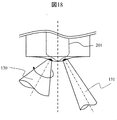
- FIG. 18 is an enlarged view of the vicinity of the fuel injection valve of the fuel spray 130 injected from the first injection hole group 143 and the fuel spray 131 injected from the second injection hole group 144.
- the 1st injection hole group 143 is comprised by the twist injection hole (301a ', 301b', 301c '), and penetration will fall because spray spreads downstream from an injection hole exit. That is, the fuel injection holes (301 a ′, 301 b ′, 301 c ′) of the first injection hole group 143 are configured with an ellipse in a cross section perpendicular to the injection hole axis 303, and the major axis direction of the ellipse depends on the injection hole axial direction.
- all the fuel injection holes (301d) of the second injection hole group 144 are compared with the minimum cross-sectional area of all the fuel injection holes (301a ′, 301b ′, 301c ′) of the first injection hole group 143. It is desirable that the minimum cross-sectional area of ', 301e', 301f ') is reduced. Thereby, compared with the fuel spray 133 injected from the fuel injection hole (301d ', 301e', 301f ') of the 2nd injection hole group 144, the flow volume is large and the spray with a small penetration can be injected.
- Valve body guide 206 ... Anchor 207 ... Core 208 ... Coil 209 ... Yoke 210 ... Spring 211 ... Connector 212 ... Fuel supply port 301 ... Injection hole 302 ... Suck chamber 303 ... injection hole central axis 304 ... valve seat surface 305 ... valve element central axis 306 ... velocity vector 307 at the injection hole outlet ... at the injection hole outlet Flows from the velocity vector 311 ... seat portion 312 ... flows from the suction chamber side
Landscapes
- Engineering & Computer Science (AREA)
- Chemical & Material Sciences (AREA)
- Combustion & Propulsion (AREA)
- Mechanical Engineering (AREA)
- General Engineering & Computer Science (AREA)
- Fuel-Injection Apparatus (AREA)
- Combustion Methods Of Internal-Combustion Engines (AREA)
- Cylinder Crankcases Of Internal Combustion Engines (AREA)
- Electrical Control Of Air Or Fuel Supplied To Internal-Combustion Engine (AREA)
- Combined Controls Of Internal Combustion Engines (AREA)
Abstract
本発明の目的は、燃焼室内に高均質な燃料噴霧が形成でき、かつ壁面付着を低減する燃料噴射弁を提供することにある。このため本発明の燃料噴射弁は、燃焼室に直接、燃料を噴射する燃料噴射弁において、燃料噴射孔の中心軸がピストン上面中心よりも点火プラグ先端部の側を指向する第1噴射孔グループと、燃料噴射孔の中心軸が前記点火プラグ先端部よりも前記ピストン上面中心の側を指向する第2噴射孔グループを有し、前記第1噴射孔グループの燃料噴射孔は、前記第2噴射孔グループの燃料噴射孔から噴射される噴霧の流量よりも大きく、かつペネトレーションが小さくなるように構成される。
Description
本発明は、ガソリンエンジン等の内燃機関に用いられる燃料噴射弁、及びエンジンシステムに関する。
近年、自動車におけるガソリンエンジンは燃費改善の要求が高まっており、燃費に優れたエンジンとして、燃焼室内に燃料を直接噴射し、噴射された燃料と吸入空気との混合気を点火プラグで点火して爆発させる筒内噴射式エンジンが普及してきている。しかし、筒内噴射式エンジンは噴射地点から壁面までの距離が短いために燃料が燃焼室内に付着しやすく、温度の低い壁面に付着した燃料が不完全燃焼することで発生する粒子状物質(Particulate Matter:PM)の抑制が課題となっている。この課題を解決するためには、燃焼室内の混合気形成の最適化が必要である。
また、近年では、燃料と空気との理論混合比(ストイキ)よりも空気の比率を高くする希薄(リーン)燃焼を行い、冷却損失を低減し熱効率を向上する技術が注目されている。しかしながら、リーン燃焼では、燃焼室内の燃焼速度が低下することによってエンジンの効率が低下したり、異常燃焼が起こるなどの問題がある。この問題を解決するため、例えば特許文献1には、吸気ポートにバルブを設置し、希薄燃焼時に流路を絞り高速流を偏在させ、燃焼室内の流動(タンブル)を強化することで、燃焼速度を向上する技術が記載されている。一方で、希薄混合気を筒内に均質に分布させて燃焼する、均質希薄燃焼の高効率化のためには、均質度が高く、壁面への付着量の小さい噴霧の実現が求められる。特許文献2には、空気流動の小さい低回転領域での噴霧を最適化する技術が記載されている。
特許文献2に開示されている技術は、空気流動の小さい低回転領域での噴霧を最適化する。しかしながら、特許文献2に開示されている技術には、タンブル制御バルブ閉弁時の高速流が偏在する場合についての記載はなく、高均質混合気の形成と壁面付着の低減は困難であった。
以上の課題を鑑みて、本発明の目的は、燃焼室内に高均質な燃料噴霧が形成でき、かつ壁面付着を低減する燃料噴射弁を提供することにある。
上記課題を解決するために、本発明の燃料噴射弁は、燃焼室に直接、燃料を噴射する燃料噴射弁において、燃料噴射孔の中心軸がピストン上面中心よりも点火プラグ先端部の側を指向する第1噴射孔グループと、燃料噴射孔の中心軸が前記点火プラグ先端部よりも前記ピストン上面中心の側を指向する第2噴射孔グループを有し、前記第1噴射孔グループの燃料噴射孔は、前記第2噴射孔グループの燃料噴射孔から噴射される噴霧の流量よりも大きく、かつペネトレーションが小さくなるように構成される。
本発明によれば、燃焼室内に高均質な燃料噴霧が形成でき、かつ壁面付着を低減する燃料噴射弁を提供することができる。本発明のその他の構成、作用、効果については以下の実施例において詳細に説明する。
以下、本発明に係る実施例を説明する。
本発明の第1の実施例に係る内燃機関および燃料噴射弁(インジェクタ)について、図1と図2を用いて以下説明する。
図1は、筒内噴射式エンジンの構成の概要を示した図である。図1を用いて筒内噴射式エンジンの基本的な動作を説明する。図1において、シリンダヘッド101とシリンダブロック102、シリンダブロック102に挿入されたピストン103により燃焼室104が形成され、燃料室104に向けて吸気管105と排気管106がそれぞれ2つに分岐して接続されている。吸気管105の開口部には吸気弁107が、排気管106の開口部には排気弁108がそれぞれ設けられ、カム動作方式により開閉するように動作する。
図1は、筒内噴射式エンジンの構成の概要を示した図である。図1を用いて筒内噴射式エンジンの基本的な動作を説明する。図1において、シリンダヘッド101とシリンダブロック102、シリンダブロック102に挿入されたピストン103により燃焼室104が形成され、燃料室104に向けて吸気管105と排気管106がそれぞれ2つに分岐して接続されている。吸気管105の開口部には吸気弁107が、排気管106の開口部には排気弁108がそれぞれ設けられ、カム動作方式により開閉するように動作する。
ピストン103はコンロッド114を介してクランク軸115と連結されており、クランク角センサ116によりエンジン回転数を検知できる。回転数の値はECU(エンジンコントロールユニット)118に送られる。クランク軸115には図示しないセルモータが連結され、エンジン始動時にはセルモータによりクランク軸115を回転させ始動することができる。シリンダブロック102には水温センサ117が備えられ、図示しないエンジン冷却水の温度を検知できる。エンジン冷却水の温度はECU118に送られる。
図1は1気筒のみの記述だが、吸気管105の上流には図示しないコレクタが備えられ、気筒ごとに空気を分配する。コレクタの上流には図示しないエアフローセンサとスロットル弁が備えられ、燃料室104に吸入される空気量をスロットル弁の開度によって調節できる。
燃料は燃料タンク109に貯蔵され、フィードポンプ110によって高圧燃料ポンプ111に送られる。フィードポンプ110は燃料を0.3MPa程度まで昇圧して高圧燃料ポンプ111に送る。高圧燃料ポンプ111により昇圧された燃料はコモンレール112に送られる。高圧燃料ポンプ111は燃料を30MPa程度まで昇圧してコモンレール112に送る。コモンレール112には燃圧センサ113が設けられ、燃料圧力(燃圧)を検知する。燃圧の値はECU118に送られる。
図2は、本実施例の燃料噴射弁の例として、電磁式燃料噴射弁の例を示す図である。図2を用いて噴射装置の基本的な動作を説明する。図2において、燃料は燃料供給口212から供給され、燃料噴射弁の内部に供給される。図2に示す電磁式燃料噴射弁119は、通常時閉型の電磁駆動式であって、コイル208に通電がないときには、弁体201がスプリング210によって付勢され、ノズル体204に溶接などで接合されたシート部材202に押し付けられ、燃料がシールされるようになっている。弁体201の弁体シート部が着座するシート部材202のシート部の下流側には複数の燃料噴射孔301(噴射孔)が形成される。このとき、筒内噴射用燃料噴射弁では、供給される燃料圧力がおよそ1MPaから50MPaの範囲である。
コネクタ211を介してコイル208に通電されると、電磁弁の磁気回路を構成するコア(固定コア)207、ヨーク209、アンカー206に磁束密度を生じて、空隙のあるコア207とアンカー206の間に磁気吸引力を生じる。磁気吸引力が、スプリング210の付勢力と前述の燃料圧力による下流方向への付勢力を合算した付勢力よりも大きくなると、弁体201はガイド部材203、弁体ガイド205にガイドされながらアンカー206によってコア207側に吸引され、開弁状態となる。開弁状態となると、シート部材202のシート部から弁体201の弁体シート部が離座するため、これらの間に隙間が生じる。これにより高圧の燃料がシート部材202に形成された燃料噴射孔を介して、噴射される。燃料の噴射が開始されると、燃料圧力として与えられたエネルギは運動エネルギに変換され、燃料噴射弁下端部に空いた燃料噴射孔に至り噴射される。
図3は、図1と同じ断面の、燃焼室内の拡大図である。気筒の径方向側面部に燃料噴射弁119が備えられている。点火プラグ120は気筒の軸方向上面部で排気管106の近傍に備えられている。吸気ポート105には隔壁121が取り付けられる。この隔壁121は吸気ポート105の通路を気筒軸方向おいて上下に仕切るように構成される。つまり、吸気ポート105の空気流路が隔壁121により上側流路と下側流路とに分けられる。タンブル制御バルブ122は隔壁121の上流側に配置され、吸気ポート105の流路の一部が開閉されるように制御される。具体的にはタンブル制御バルブ122は隔壁121によって形成される吸気ポート105の下側流路の開閉を行う。
ECU118はセンサの信号をモニタし、第1の燃料噴射弁119や点火プラグ120、高圧燃料ポンプ111、タンブル制御バルブ122といったデバイスの作動を制御できる。ECU118のROMには一般的に用いられるエンジン回転数や水温、空燃比に応じた各種デバイスの設定値がマップデータとして記録されている。図3は、タンブル制御バルブ122が開き状態であり、吸気行程において隔壁121の上側流路を通る流れ123と隔壁の下部流路を通る流れ124が形成される。
図4は図3と同じ断面の、タンブル制御バルブ122が閉じた状態を示した図である。吸気ポート105に付与された隔壁121の上側流路を通る流れ125は、燃焼室内に強い流れを形成する。一方、隔壁121に阻害されることで、下側流路の流れ126は流れ125に比べて弱い流れとなる。このとき、バルブの中心軸127をピストン上部まで延在させて燃焼室内の領域を領域128と領域129に分けた場合、吸気行程において、領域128には強い流れが形成し、領域129には弱い流れが形成される。
図5は、図4と同じ断面において、ピストン103が下降中に燃料噴射弁119から燃料を噴射した場合の模式図である。インジェクタ119から流動の強い領域128へと燃料噴霧130を噴射し、流動の弱い領域129へと燃料噴霧131を噴射する。すなわち、燃焼室104に直接、燃料を噴射するインジェクタ119において、燃料噴射孔301の中心軸305がピストン上面中心103aよりも点火プラグ先端部120aの側を指向する第1噴射孔グループ140と、燃料噴射孔の中心軸が点火プラグ先端部120aよりもピストン上面中心103aの側を指向する第2噴射孔グループ141を有する。そして第1噴射孔グループ140の燃料噴射孔(301a、301b、301c)から燃料噴霧130を噴射し、第2噴射孔グループ141の燃料噴射孔(301d、301e、301f)から燃料噴霧131を噴射する。なお、燃料噴霧130は第1噴射孔グループ140の燃料噴射孔(301a、301b、301c)のうちの一つの燃料噴射孔からの燃料噴霧を示し、同様に燃料噴霧131は第2噴射孔グループ141の燃料噴射孔(301d、301e、301f)のうちの一つの燃料噴射孔からの燃料噴霧を示す。132は燃料噴霧130の中心軸の噴霧方向を示し、これは第1噴射孔グループ140の燃料噴射孔(301a、301b、301c)の中心軸とほぼ同様の方向である。同様に133は燃料噴霧131の中心軸の噴霧方向を示し、これは第2噴射孔グループ141の燃料噴射孔(301d、301e、301f)の中心軸とほぼ同様の方向である。
そして本実施例の燃料噴射弁は、ピストン103が下死点にいる状態において、第1噴射孔グループ140の燃料噴射孔(301a、301b、301c)は、第2噴射孔グループ141の燃料噴射孔(301d、301e、301f)から噴射される噴霧の流量よりも大きく、かつペネトレーションが小さくなるように構成される。つまり、流動の強い領域128に対しては、第1噴射孔グループ140の燃料噴射孔(301a、301b、301c)により領域129への噴霧に比べて燃料の噴射流量が大きく、かつ噴霧の貫徹力(ペネトレーション)が小さくなるようにする。これにより、強い流動による燃料の分散効果を得ることができ、かつシリンダへの燃料の付着を低減することができる。一方、流動の弱い領域129に対しては第2噴射孔グループ141の燃料噴射孔(301d、301e、301f)により、領域128への噴霧に比べて燃料噴霧131が小流量とし、また流れによる分散性も弱いため、噴霧の貫徹力(ペネトレーション)が燃料噴霧130に比べて強くなるようにする。これにより、燃料噴霧131の有する運動量で燃料を拡散させることができる。
すなわち、第1噴射孔グループの噴射孔から噴射される噴霧は、第2噴射孔グループの噴射孔から噴射される噴霧の流量よりも大きく、かつペネトレーションが小さくなるように構成することで、流動の強い領域128と流動の弱い領域129のそれぞれに対し、分散性に優れ、付着量の少ない噴霧を実現できる。
図6は、燃料噴射直後における燃料の存在領域を示した図である。燃料噴霧130は流量が多いために、広い範囲で燃料分布130aを形成し、燃料噴霧131は流動の弱い領域に燃料分布131aを形成する。このとき、筒内に形成された順タンブル方向(図の時計回り方向)のタンブル134によって、燃料分布は順タンブル方向に移動する。
図7は、ピストン103が上方向に動作する圧縮行程中(圧縮行程初期)の燃料室内の燃料分布を示した図である。燃料分布130aと燃料分布131aは順タンブル方向に移動し、それぞれ燃料分布130bと燃料分布131bを形成する。図8は圧縮行程後期の燃料分布を示した図である。燃料分布130bと燃料分布131bは、燃料室内に均質混合気135を形成する。
以上の通り本実施例の燃料噴射弁は、上記したように燃料噴射孔301の中心軸303がピストン上面中心103aよりも点火プラグ先端部120aの側を指向する第1噴射孔グループ140と、燃料噴射孔301の中心軸303が点火プラグ先端部120aよりもピストン上面中心103aの側を指向する第2噴射孔グループ141を有する。そして、第1噴射孔グループ140の燃料噴射孔(301a、301b、301c)は、第2噴射孔グループ141の燃料噴射孔(301d、301e、301f)から噴射される噴霧の流量よりも大きく、かつペネトレーションが小さくなるように構成される。これにより、流動の強い領域に対してはタンブル流による分散を、流動の弱い領域に対しては噴霧の運動量による分散を行う。よって、タンブル制御弁が閉まり高速流動が偏在する燃焼室においても、均質性の高く、壁面への付着の少ない混合気を形成することができる。
図9は、燃料噴射弁119に付与された第1噴射孔グループ140の燃料噴射孔(301a、301b、301c)から噴射される燃料噴霧130と、第2噴射孔グループ141の燃料噴射孔(301d、301e、301f)から噴射される燃料噴霧131の模式図である。L130は第1噴射孔グループ140の燃料噴射孔(301a、301b、301c)から噴射される燃料噴霧130のペネトレーションを表し、L131は第2噴射孔グループ141の燃料噴射孔(301d、301e、301f)から噴射される燃料噴霧131のペネトレーションを表す。第1噴射孔グループ140の燃料噴射孔(301a、301b、301c)から噴射される噴霧は、第2噴射孔グループ141の燃料噴射孔(301d、301e、301f)から噴射される噴霧の流量よりも大きく、かつペネトレーションL130がペネトレーションL131よりも小さくなるように構成される。
図10は、燃料噴射弁の先端の拡大図である。本実施例は、第1噴射孔グループ140が3つの燃料噴射孔(301a、301b、301c)からなり、第2噴射孔グループ141が3つの燃料噴射孔(301d、301e、301f)からなる、6噴射孔のマルチホール型の燃料噴射弁である。ただし、本発明は各噴射孔グループ(140、141)の燃料噴射孔の数が3つに限定されるものではない。本実施例において、第1噴射孔グループ140の燃料噴射孔(301a、301b、301c)と第2噴射孔グループ141の燃料噴射孔(301d、301e、301f)とが異なる孔径となるように構成される。具体的には第1噴射孔グループ140の燃料噴射孔(301a、301b、301c)に比べ、第2噴射孔グループ141の燃料噴射孔(301d、301e、301f)の孔径の方が小さくなるように構成される。これにより第2噴射孔グループ141の燃料噴射孔(301d、301e、301f)から噴射される噴霧に比べ、第1噴射孔グループ140の燃料噴射孔(301a、301b、301c)から噴射される噴霧の流量を大きくすることができる。第2噴射孔グループ141の燃料噴射孔(301a、301b、301c)の中心軸303に垂直な方向の最小断面積が、第1噴射孔グループ140の燃料噴射孔(301a、301b、301c)の中心軸303に垂直な方向の最小断面積と比べて小さくなるように構成されると言っても良い。
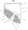
図11は、第1噴射孔グループ140に属する燃料噴射孔(301a、301b、301c)の噴射孔軸303と、弁体軸305に平行な、燃料噴射弁先端の拡大断面図である。燃料噴射弁先端は、弁体201、シート部材202、サック室302で、弁座面304などにより構成される。燃料は弁体201とシート部材202の隙間を通り、流れ311の経路を通って燃料噴射孔(301a、301b、301c)に流入するか、サック室302を経由し、流れ312の経路を通って燃料噴射孔(301a、301b、301c)に流入する。本実施例では、第1噴射孔グループ140の燃料噴射孔(301a、301b、301c)は、出口に向かって断面積が拡大するように構成される。出口に向かって流路が広がることで、主流方向の流速が低下するとともに、噴射孔出口での噴射方向306が広がり、ペネトレーションが低下する。
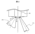
図12は、第1噴射孔グループ140から噴射される燃料噴霧130と、第2噴射孔グループ141から噴射される燃料噴霧131の、燃料噴射弁近傍の拡大図である。第1噴射孔グループ140の燃料噴射孔(301a、301b、301c)は上記したように出口に向かって広がりテーパを有しており、噴射孔出口より下流で噴霧が広がることで、ペネトレーションが低下する。すなわち、第1噴射孔グループ140の燃料噴射孔(301a、301b、301c)は噴射出口に向かって断面積が増加するテーパを有することで、第2噴射孔グループ141の燃料噴射孔(301d、301e、301f)から噴射される燃料噴霧131に比べ、ペネトレーションの小さい燃料噴霧130を噴射することができる。なお、第2噴射孔グループ141の燃料噴孔(301d、301e、301f)は、噴孔出口に向かって断面積が小さくなる、絞りテーパ形状としても良い。第2噴射孔グループ141の燃料噴孔(301d、301e、301f)を絞りテーパ形状とすることで、噴射孔出口での噴霧角が小さくなり、ペネトレーションが大きくなる。
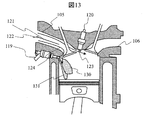
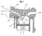
次に、タンブル制御バルブ122の開度による制御方法を、図13を用いて説明する。図13は、タンブル制御バルブ122が開き状態での、燃料噴射を表した図である。タンブル制御バルブ122が開いた状態では、隔壁121の下部からの流れ込み124が発生することで、下向きの強い流れが形成される。これにより、貫徹力の弱い、第1噴射孔グループ140に属する燃料噴射孔(301a、301b、301c)から噴射される燃料噴霧は、流れに負けて下向きに流れてしまい、燃焼室内に十分に分散されない。そこで、燃料噴射圧力を上昇させることで、図14に示すように、噴霧の貫徹力を上昇させ、燃焼室内に十分に燃料を分散させることができる。すなわち、タンブル制御バルブ122の開度を大きくするに従って、燃料の供給圧力を高めるように制御することで、燃焼室内に均質な混合気を形成することができる。具体的にはコモンレール112に燃料を供給する高圧燃料ポンプ111を制御することで供給燃料が高くなるように制御する。
図15に、タンブル制御バルブ122と燃料供給圧力の関係を示す。内燃機関の制御装置であるECU118は、要求負荷が高い場合には、タンブル制御バルブ122の開度を上げる。このとき、燃料供給圧力をタンブル制御バルブ122の開度に応じて上げることで、第1噴射孔グループ140の燃料噴射孔(301a、301b、301c)から噴射される噴霧の貫徹力を高め、燃焼室内に均質な混合気を形成することができる。一方、エンジンへの要求負荷が中・低負荷の場合には、リーン均質燃焼モードへと変わり、タンブル制御バルブ122の開度を小さくするように制御する。このとき、均質混合気と低付着量を両立するため、燃料供給圧力を下げ、第1噴射孔グループ140の燃料噴射孔(301a、301b、301c)から噴射される噴霧の貫徹力を下げるように制御する。
以上の通り図3に示したように、本実施例のエンジンシステムでは気筒の空気入口側の吸気ポート105に空気流路を気筒の軸方向上下に分ける隔壁121が設けられる。そしてこのエンジンシステムにおいて、隔壁121の下側流路を開閉する絞り弁122が設けられている。またこのエンジンシステムにおいて、低負荷、又は中負荷の状態で絞り弁122が閉じられるように制御する制御部を備えることが望ましい。またこのエンジンシステムにおいて、絞り弁122の開度を大きくするに従って、燃料噴射弁119に供給する燃料圧力を高めるように制御する制御部(ECU)を備えることが望ましい。
以上の本実施例によれば、吸気ポート105の流路を絞り燃焼室内に高速流が形成されている場合に、高均質で、壁面付着を低減する燃料噴射弁、又はエンジンシステムを提供することが可能となる。
本発明の第2の実施例に係る燃料噴射弁について、図16から図18を用いて以下説明する。実施例1と筒内噴射式エンジン、及び燃料噴射弁の基本的な構成は同じなので説明を省略する。また同様の符号は実施例1と同じ機能を示すため説明を省略する。本実施例に係る燃料噴射弁は、燃料噴射孔の中心軸がピストン上面中心103aよりも点火プラグ先端部120aの側を指向する第1噴射孔グループ143に属する燃料噴射孔(301a´、301b´、301c´)において、噴孔軸に垂直な方向の断面がオーバル形状で構成され、オーバル形状の長軸方向が噴射孔軸方向によって変化するねじり噴射孔により構成される。その他の構成は第1の実施例と同一とする。燃料噴射孔の中心軸が点火プラグ先端部120aよりもピストン上面中心103aの側を指向する第2噴射孔グループ144に属する燃料噴射孔(301d´、301e´、301f´)については実施例1の燃料噴射孔(301d、301e、301f)と同様に真円形状で形成される。なお、オーバル形状は卵形、長円形、又は楕円形などを含む形状であるが、本実施例では特に楕円形であることが望ましい。以下においては楕円を例として説明するが、本発明はこれに限定されるわけではない。
図16は、図10と同様の、燃料噴射弁先端の拡大図である。第2の実施例では、第1噴射孔グループ143が楕円噴孔(301a´、301b´、301c´)で構成される。図17(a)に、図11と同様の、燃料噴射弁先端の拡大断面図を示す。本実施例に係る燃料噴射弁では、楕円噴孔(301a´、301b´、301c´)の中心軸303に垂直な方向の断面は楕円で構成される。なお、断面の一部は真円としてもよい。図17(b)に、噴射孔入口と噴射孔出口での断面形状を示す。本実施例では、楕円噴孔(301a´、301b´、301c´)の噴射孔入口の断面は真円で構成し、噴射孔出口の断面を楕円で構成する。また、楕円の長軸方向は、噴射孔軸方向によって変化するねじり噴射孔である。ねじり噴射孔を通る流れは、噴射孔の軸周りの回転方向の流れ(スワール)を形成する。
図18は、第1噴射孔グループ143から噴射される燃料噴霧130と、第2噴射孔グループ144から噴射される燃料噴霧131の、燃料噴射弁近傍の拡大図である。第1噴射孔グループ143はねじり噴射孔(301a´、301b´、301c´)により構成され、噴射孔出口より下流で噴霧が広がることで、ペネトレーションが低下する。すなわち、第1噴射孔グループ143の燃料噴射孔(301a´、301b´、301c´)は噴孔軸303に垂直な方向の断面が楕円で構成され、楕円の長軸方向が噴射孔軸方向によって変化するねじり噴射孔により構成される。また実施例1と同様に第1噴射孔グループ143の全ての燃料噴射孔(301a´、301b´、301c´)の最小断面積と比べて第2噴射孔グループ144の全ての燃料噴射孔(301d´、301e´、301f´)の最小断面積が小さくなるように構成されることが望ましい。これにより、第2噴射孔グループ144の燃料噴射孔(301d´、301e´、301f´)から噴射される燃料噴霧133に比べ、流量は大きく、かつ、ペネトレーションの小さい噴霧を噴射することができる。
101…シリンダヘッド
102…シリンダブロック
103…ピストン
104…燃焼室
105…吸気管
106…排気管
107…吸気弁
108…排気弁
109…燃料タンク
110…フィードポンプ
111…高圧燃料ポンプ
112…コモンレール
113…燃圧センサ
114…コンロッド
115…クランク軸
116…クランク角センサ
117…水温センサ
118…ECU
119…燃料噴射弁
120…点火プラグ
121…隔壁
122…タンブル制御バルブ
123…隔壁上部流れ
124…隔壁下部流れ
125…隔壁上部流れ(タンブル制御バルブ閉状態時)
126…隔壁下部流れ(タンブル制御バルブ閉状態時)
127…吸気バルブ中心軸
128…強流動領域
129…弱流動領域
130…第1噴射孔グループの噴射孔からの噴霧
131…第2噴射孔グループの噴射孔からの噴霧
132…第1噴射孔グループの噴射孔からの噴霧方向
133…第2噴射孔グループの噴射孔からの噴霧方向
134…タンブル流
135…混合気
140…第1噴射孔グループの噴射孔
141…第2噴射孔グループの噴射孔
201…弁体
202…シート部材
203…ガイド部材
204…ノズル体
205…弁体ガイド
206…アンカー
207…コア
208…コイル
209…ヨーク
210…スプリング
211…コネクタ
212…燃料供給口
301…噴射孔
302…サック室
303…噴射孔中心軸
304…弁座面
305…弁体中心軸
306…噴孔出口での速度ベクトル
307…噴孔出口での速度ベクトル
311…シート部側からの流れ込み
312…サック室側からの流れ込み
Claims (10)
- 燃焼室に直接、燃料を噴射する燃料噴射弁において、燃料噴射孔の中心軸がピストン上面中心よりも点火プラグ先端部の側を指向する第1噴射孔グループと、燃料噴射孔の中心軸が前記点火プラグ先端部よりも前記ピストン上面中心の側を指向する第2噴射孔グループを有し、前記第1噴射孔グループの燃料噴射孔は、前記第2噴射孔グループの燃料噴射孔から噴射される噴霧の流量よりも大きく、かつペネトレーションが小さくなるように構成される燃料噴射弁。
- 請求項1に記載の燃料噴射弁において、前記第1噴射孔グループの燃料噴射孔は噴射出口に向かって断面積が増加するテーパを有するように構成された燃料噴射弁。
- 請求項1に記載の燃料噴射弁において、前記第2噴射孔グループの燃料噴射孔の中心軸に垂直な方向の最小断面積が、前記第1噴射孔グループの燃料噴射孔の中心軸に垂直な方向の最小断面積と比べて小さくなるように構成された燃料噴射弁。
- 請求項1に記載の燃料噴射弁において、前記第1噴射孔グループの燃料噴射孔の中心軸に垂直な方向の断面がオーバル形状であり、オーバル形状の長軸方向が噴射孔軸方向によって変化するねじり噴射孔により構成された燃料噴射弁。
- 請求項1に記載の燃料噴射弁において、前記第1噴射孔グループの燃料噴射孔の入口の断面が真円で構成され、出口の断面が楕円で構成された燃料噴射弁。
- 請求項1に記載の燃料噴射弁において、前記第1噴射孔グループの全ての燃料噴射孔の最小断面積と比べて前記第2噴射孔グループの全ての燃料噴射孔の最小断面積が小さくなるように構成された燃料噴射弁。
- 請求項1に記載の燃料噴射弁が気筒に取り付けられ、
前記気筒の空気入口側の吸気ポートに空気流路を前記気筒の軸方向上下に分ける隔壁が設けられたエンジンシステム。 - 請求項7に記載のエンジンシステムにおいて、
前記隔壁の下側流路を開閉する絞り弁が設けられたエンジンシステム。 - 請求項8に記載のエンジンシステムにおいて、
低負荷、又は中負荷の状態で前記絞り弁が閉じられるように制御する制御部を備えたエンジンシステム。 - 請求項8に記載のエンジンシステムにおいて、絞り弁の開度を大きくするに従って、前記燃料噴射弁に供給する燃料圧力を高めるように制御する制御部を備えたエンジンシステム。
Applications Claiming Priority (2)
| Application Number | Priority Date | Filing Date | Title |
|---|---|---|---|
| JP2017-107319 | 2017-05-31 | ||
| JP2017107319A JP6862284B2 (ja) | 2017-05-31 | 2017-05-31 | 燃料噴射弁及びエンジンシステム |
Publications (1)
| Publication Number | Publication Date |
|---|---|
| WO2018221076A1 true WO2018221076A1 (ja) | 2018-12-06 |
Family
ID=64455385
Family Applications (1)
| Application Number | Title | Priority Date | Filing Date |
|---|---|---|---|
| PCT/JP2018/016524 Ceased WO2018221076A1 (ja) | 2017-05-31 | 2018-04-24 | 燃料噴射弁及びエンジンシステム |
Country Status (2)
| Country | Link |
|---|---|
| JP (1) | JP6862284B2 (ja) |
| WO (1) | WO2018221076A1 (ja) |
Cited By (1)
| Publication number | Priority date | Publication date | Assignee | Title |
|---|---|---|---|---|
| CN117090721A (zh) * | 2022-05-20 | 2023-11-21 | 丰田自动车株式会社 | 燃料喷射装置 |
Families Citing this family (3)
| Publication number | Priority date | Publication date | Assignee | Title |
|---|---|---|---|---|
| JP7298484B2 (ja) * | 2020-01-10 | 2023-06-27 | トヨタ自動車株式会社 | 内燃機関の吸気構造 |
| JP7529580B2 (ja) * | 2021-01-19 | 2024-08-06 | 本田技研工業株式会社 | 内燃機関 |
| JP7632269B2 (ja) * | 2021-05-28 | 2025-02-19 | 株式会社デンソー | ガスエンジンの制御装置、及びプログラム |
Citations (7)
| Publication number | Priority date | Publication date | Assignee | Title |
|---|---|---|---|---|
| JPH10339151A (ja) * | 1997-06-11 | 1998-12-22 | Nissan Motor Co Ltd | 筒内直接噴射式火花点火エンジン |
| WO2000077359A1 (en) * | 1999-06-11 | 2000-12-21 | Hitachi, Ltd. | Cylinder injection engine and method of combusting the engine |
| JP2007092635A (ja) * | 2005-09-28 | 2007-04-12 | Mazda Motor Corp | 火花点火式直噴エンジン |
| JP2007315276A (ja) * | 2006-05-25 | 2007-12-06 | Nissan Motor Co Ltd | マルチホール型インジェクタ |
| JP2015025392A (ja) * | 2013-07-25 | 2015-02-05 | トヨタ自動車株式会社 | 燃料噴射弁 |
| JP2017044174A (ja) * | 2015-08-28 | 2017-03-02 | 日立オートモティブシステムズ株式会社 | 燃料噴射弁 |
| WO2017047248A1 (ja) * | 2015-09-17 | 2017-03-23 | 日立オートモティブシステムズ株式会社 | 燃料噴射制御装置 |
Family Cites Families (15)
| Publication number | Priority date | Publication date | Assignee | Title |
|---|---|---|---|---|
| JP3926989B2 (ja) * | 2001-02-01 | 2007-06-06 | 株式会社日立製作所 | 筒内噴射式火花点火エンジンの制御装置 |
| JP2005248857A (ja) * | 2004-03-04 | 2005-09-15 | Mitsubishi Electric Corp | 内燃機関の燃焼制御装置 |
| JP4542018B2 (ja) * | 2005-10-12 | 2010-09-08 | 日立オートモティブシステムズ株式会社 | エンジンの燃料噴射制御方法、及び、それに用いられるインジェクタを有するエンジン |
| JP2007138746A (ja) * | 2005-11-15 | 2007-06-07 | Hitachi Ltd | 燃料供給装置 |
| JP2007138779A (ja) * | 2005-11-16 | 2007-06-07 | Nissan Motor Co Ltd | 筒内噴射内燃機関 |
| JP2008075471A (ja) * | 2006-09-19 | 2008-04-03 | Nissan Motor Co Ltd | 内燃機関の燃料噴射制御装置 |
| JP2008151020A (ja) * | 2006-12-18 | 2008-07-03 | Hitachi Ltd | 段差を備えたピストンを有した筒内噴射エンジンと制御装置 |
| JP2009024683A (ja) * | 2007-07-24 | 2009-02-05 | Hitachi Ltd | 複数の噴孔を有するインジェクタ、当該インジェクタを備えた筒内ガソリン噴射型内燃機関とその制御方法 |
| JP2009085041A (ja) * | 2007-09-28 | 2009-04-23 | Hitachi Ltd | 燃料噴射装置 |
| JP2010101290A (ja) * | 2008-10-27 | 2010-05-06 | Denso Corp | 燃料噴射弁 |
| JP2010249125A (ja) * | 2009-03-23 | 2010-11-04 | Denso Corp | 燃料噴射弁 |
| US9435308B2 (en) * | 2011-07-11 | 2016-09-06 | Bosch Corporation | Fuel injection valve, internal combustion engine and fuel injection method |
| JP6138502B2 (ja) * | 2013-02-04 | 2017-05-31 | 日立オートモティブシステムズ株式会社 | 燃料噴射弁 |
| JP2016098702A (ja) * | 2014-11-20 | 2016-05-30 | 株式会社日本自動車部品総合研究所 | 燃料噴射弁 |
| JP2017031980A (ja) * | 2016-10-05 | 2017-02-09 | 株式会社デンソー | 燃料噴射弁 |
-
2017
- 2017-05-31 JP JP2017107319A patent/JP6862284B2/ja active Active
-
2018
- 2018-04-24 WO PCT/JP2018/016524 patent/WO2018221076A1/ja not_active Ceased
Patent Citations (7)
| Publication number | Priority date | Publication date | Assignee | Title |
|---|---|---|---|---|
| JPH10339151A (ja) * | 1997-06-11 | 1998-12-22 | Nissan Motor Co Ltd | 筒内直接噴射式火花点火エンジン |
| WO2000077359A1 (en) * | 1999-06-11 | 2000-12-21 | Hitachi, Ltd. | Cylinder injection engine and method of combusting the engine |
| JP2007092635A (ja) * | 2005-09-28 | 2007-04-12 | Mazda Motor Corp | 火花点火式直噴エンジン |
| JP2007315276A (ja) * | 2006-05-25 | 2007-12-06 | Nissan Motor Co Ltd | マルチホール型インジェクタ |
| JP2015025392A (ja) * | 2013-07-25 | 2015-02-05 | トヨタ自動車株式会社 | 燃料噴射弁 |
| JP2017044174A (ja) * | 2015-08-28 | 2017-03-02 | 日立オートモティブシステムズ株式会社 | 燃料噴射弁 |
| WO2017047248A1 (ja) * | 2015-09-17 | 2017-03-23 | 日立オートモティブシステムズ株式会社 | 燃料噴射制御装置 |
Cited By (1)
| Publication number | Priority date | Publication date | Assignee | Title |
|---|---|---|---|---|
| CN117090721A (zh) * | 2022-05-20 | 2023-11-21 | 丰田自动车株式会社 | 燃料喷射装置 |
Also Published As
| Publication number | Publication date |
|---|---|
| JP6862284B2 (ja) | 2021-04-21 |
| JP2018204445A (ja) | 2018-12-27 |
Similar Documents
| Publication | Publication Date | Title |
|---|---|---|
| KR100647754B1 (ko) | 실린더 내부 분사형 내연 기관의 연료 분사 장치 및 연료분사 방법 | |
| JP4170902B2 (ja) | シリンダ内直接噴射式内燃機関 | |
| JP6862284B2 (ja) | 燃料噴射弁及びエンジンシステム | |
| US11136954B2 (en) | Fuel injection valve | |
| US20120138712A1 (en) | Injector for vehicle | |
| JP2007231924A (ja) | 内燃機関用燃料噴射弁 | |
| JPH11159424A (ja) | 内燃機関の燃料噴射装置 | |
| JP5274701B1 (ja) | 筒内噴射式内燃機関の制御装置 | |
| JP5072765B2 (ja) | 火花点火式ガス燃料内燃機関 | |
| JP5783701B2 (ja) | 筒内噴射エンジンの制御装置 | |
| JP4224666B2 (ja) | 燃料噴射ノズルおよびその加工方法 | |
| JP2009002191A (ja) | 内燃機関の吸気制御装置 | |
| JP6568808B2 (ja) | 燃料噴射弁の制御装置 | |
| JP4349374B2 (ja) | 筒内噴射型内燃機関 | |
| JP7013133B2 (ja) | 車両用制御装置 | |
| JP2013181454A (ja) | 内燃機関の燃料噴射システム | |
| JP2009085041A (ja) | 燃料噴射装置 | |
| US10677208B2 (en) | Fuel injection device | |
| JP6695476B2 (ja) | 燃料噴射装置 | |
| JP2020012377A (ja) | 燃料噴射弁 | |
| JP4276955B2 (ja) | 燃料噴射システム | |
| JP3969156B2 (ja) | 内燃機関の燃料噴射制御装置 | |
| JP2010031684A (ja) | 火花点火式内燃機関 | |
| JP2008075538A (ja) | 燃料噴射装置 | |
| JP2004270450A (ja) | 内燃機関の燃料噴射装置および燃料噴射方法 |
Legal Events
| Date | Code | Title | Description |
|---|---|---|---|
| 121 | Ep: the epo has been informed by wipo that ep was designated in this application |
Ref document number: 18810060 Country of ref document: EP Kind code of ref document: A1 |
|
| NENP | Non-entry into the national phase |
Ref country code: DE |
|
| 122 | Ep: pct application non-entry in european phase |
Ref document number: 18810060 Country of ref document: EP Kind code of ref document: A1 |