WO2018216342A1 - Appareil de traitement d'informations, procédé de traitement d'informations et programme - Google Patents
Appareil de traitement d'informations, procédé de traitement d'informations et programme Download PDFInfo
- Publication number
- WO2018216342A1 WO2018216342A1 PCT/JP2018/012018 JP2018012018W WO2018216342A1 WO 2018216342 A1 WO2018216342 A1 WO 2018216342A1 JP 2018012018 W JP2018012018 W JP 2018012018W WO 2018216342 A1 WO2018216342 A1 WO 2018216342A1
- Authority
- WO
- WIPO (PCT)
- Prior art keywords
- light
- unit
- information processing
- processing apparatus
- projected
- Prior art date
Links
Images


Classifications
-
- G—PHYSICS
- G06—COMPUTING; CALCULATING OR COUNTING
- G06T—IMAGE DATA PROCESSING OR GENERATION, IN GENERAL
- G06T7/00—Image analysis
- G06T7/50—Depth or shape recovery
- G06T7/507—Depth or shape recovery from shading
-
- G—PHYSICS
- G06—COMPUTING; CALCULATING OR COUNTING
- G06T—IMAGE DATA PROCESSING OR GENERATION, IN GENERAL
- G06T7/00—Image analysis
- G06T7/70—Determining position or orientation of objects or cameras
- G06T7/73—Determining position or orientation of objects or cameras using feature-based methods
- G06T7/75—Determining position or orientation of objects or cameras using feature-based methods involving models
-
- G—PHYSICS
- G01—MEASURING; TESTING
- G01S—RADIO DIRECTION-FINDING; RADIO NAVIGATION; DETERMINING DISTANCE OR VELOCITY BY USE OF RADIO WAVES; LOCATING OR PRESENCE-DETECTING BY USE OF THE REFLECTION OR RERADIATION OF RADIO WAVES; ANALOGOUS ARRANGEMENTS USING OTHER WAVES
- G01S17/00—Systems using the reflection or reradiation of electromagnetic waves other than radio waves, e.g. lidar systems
- G01S17/86—Combinations of lidar systems with systems other than lidar, radar or sonar, e.g. with direction finders
-
- G—PHYSICS
- G01—MEASURING; TESTING
- G01S—RADIO DIRECTION-FINDING; RADIO NAVIGATION; DETERMINING DISTANCE OR VELOCITY BY USE OF RADIO WAVES; LOCATING OR PRESENCE-DETECTING BY USE OF THE REFLECTION OR RERADIATION OF RADIO WAVES; ANALOGOUS ARRANGEMENTS USING OTHER WAVES
- G01S17/00—Systems using the reflection or reradiation of electromagnetic waves other than radio waves, e.g. lidar systems
- G01S17/88—Lidar systems specially adapted for specific applications
- G01S17/89—Lidar systems specially adapted for specific applications for mapping or imaging
-
- G—PHYSICS
- G06—COMPUTING; CALCULATING OR COUNTING
- G06T—IMAGE DATA PROCESSING OR GENERATION, IN GENERAL
- G06T17/00—Three dimensional [3D] modelling, e.g. data description of 3D objects
-
- G—PHYSICS
- G06—COMPUTING; CALCULATING OR COUNTING
- G06T—IMAGE DATA PROCESSING OR GENERATION, IN GENERAL
- G06T7/00—Image analysis
- G06T7/20—Analysis of motion
- G06T7/246—Analysis of motion using feature-based methods, e.g. the tracking of corners or segments
- G06T7/251—Analysis of motion using feature-based methods, e.g. the tracking of corners or segments involving models
-
- G—PHYSICS
- G06—COMPUTING; CALCULATING OR COUNTING
- G06T—IMAGE DATA PROCESSING OR GENERATION, IN GENERAL
- G06T7/00—Image analysis
- G06T7/50—Depth or shape recovery
- G06T7/521—Depth or shape recovery from laser ranging, e.g. using interferometry; from the projection of structured light
-
- G—PHYSICS
- G06—COMPUTING; CALCULATING OR COUNTING
- G06T—IMAGE DATA PROCESSING OR GENERATION, IN GENERAL
- G06T7/00—Image analysis
- G06T7/70—Determining position or orientation of objects or cameras
- G06T7/73—Determining position or orientation of objects or cameras using feature-based methods
-
- H—ELECTRICITY
- H04—ELECTRIC COMMUNICATION TECHNIQUE
- H04N—PICTORIAL COMMUNICATION, e.g. TELEVISION
- H04N23/00—Cameras or camera modules comprising electronic image sensors; Control thereof
- H04N23/56—Cameras or camera modules comprising electronic image sensors; Control thereof provided with illuminating means
-
- G—PHYSICS
- G01—MEASURING; TESTING
- G01S—RADIO DIRECTION-FINDING; RADIO NAVIGATION; DETERMINING DISTANCE OR VELOCITY BY USE OF RADIO WAVES; LOCATING OR PRESENCE-DETECTING BY USE OF THE REFLECTION OR RERADIATION OF RADIO WAVES; ANALOGOUS ARRANGEMENTS USING OTHER WAVES
- G01S17/00—Systems using the reflection or reradiation of electromagnetic waves other than radio waves, e.g. lidar systems
- G01S17/88—Lidar systems specially adapted for specific applications
- G01S17/89—Lidar systems specially adapted for specific applications for mapping or imaging
- G01S17/894—3D imaging with simultaneous measurement of time-of-flight at a 2D array of receiver pixels, e.g. time-of-flight cameras or flash lidar
-
- G—PHYSICS
- G01—MEASURING; TESTING
- G01S—RADIO DIRECTION-FINDING; RADIO NAVIGATION; DETERMINING DISTANCE OR VELOCITY BY USE OF RADIO WAVES; LOCATING OR PRESENCE-DETECTING BY USE OF THE REFLECTION OR RERADIATION OF RADIO WAVES; ANALOGOUS ARRANGEMENTS USING OTHER WAVES
- G01S7/00—Details of systems according to groups G01S13/00, G01S15/00, G01S17/00
- G01S7/48—Details of systems according to groups G01S13/00, G01S15/00, G01S17/00 of systems according to group G01S17/00
- G01S7/483—Details of pulse systems
- G01S7/484—Transmitters
-
- G—PHYSICS
- G06—COMPUTING; CALCULATING OR COUNTING
- G06T—IMAGE DATA PROCESSING OR GENERATION, IN GENERAL
- G06T2207/00—Indexing scheme for image analysis or image enhancement
- G06T2207/10—Image acquisition modality
- G06T2207/10028—Range image; Depth image; 3D point clouds
-
- G—PHYSICS
- G06—COMPUTING; CALCULATING OR COUNTING
- G06T—IMAGE DATA PROCESSING OR GENERATION, IN GENERAL
- G06T2207/00—Indexing scheme for image analysis or image enhancement
- G06T2207/10—Image acquisition modality
- G06T2207/10141—Special mode during image acquisition
- G06T2207/10152—Varying illumination
-
- G—PHYSICS
- G06—COMPUTING; CALCULATING OR COUNTING
- G06T—IMAGE DATA PROCESSING OR GENERATION, IN GENERAL
- G06T2207/00—Indexing scheme for image analysis or image enhancement
- G06T2207/30—Subject of image; Context of image processing
- G06T2207/30196—Human being; Person
- G06T2207/30201—Face
Definitions
- the present disclosure relates to an information processing apparatus, an information processing method, and a program.
- the distance measurement range and distance measurement accuracy of a depth sensor that employs an active illumination method tend to depend on the power of the device that irradiates (projects) light, and stabilizes the distance estimation with the target object.
- power consumption may increase.
- an apparatus where the amount of power that can be used is limited such as a mobile device or a mobile device
- the influence accompanying an increase in power consumption appears more remarkably. From such a background, in the case of adopting the active irradiation method, it is required to realize a technology capable of achieving both stabilization of distance estimation with a target object and suppression of power consumption. Yes.
- the present disclosure proposes an information processing apparatus, an information processing method, and a program capable of achieving both stabilization of distance estimation with a target object and suppression of power consumption.
- the distance between the predetermined viewpoint and the object is estimated based on the detection result of the light projected from the predetermined light projecting unit toward the object in the real space and reflected by the object.
- a first estimation unit; a second estimation unit that estimates at least one of a position and orientation of the predetermined viewpoint in real space based on the estimation result of the distance; and at least of the position and orientation An information processing apparatus is provided that includes a control unit that controls the light projected from the light projecting unit according to a situation related to any estimation.
- the computer projects light from a predetermined light projecting unit toward an object in real space, and based on a detection result of light reflected by the object, between the predetermined viewpoint and the object. Estimating at least one of the position and orientation of the predetermined viewpoint in real space based on the estimation result of the distance, and at least one of the position and orientation There is provided an information processing method including controlling the light projected from the light projecting unit according to a situation relating to estimation.
- the computer projects between a predetermined viewpoint and the object based on a detection result of light projected from the predetermined light projecting unit toward the object in the real space and reflected by the object.
- Estimating at least one of the position and orientation of the predetermined viewpoint in real space based on the estimation result of the distance, and at least one of the position and orientation There is provided a program for executing the control of the light projected from the light projecting unit according to a situation relating to the estimation.
- an information processing apparatus capable of achieving both stabilization of distance estimation with respect to a target object and suppression of power consumption. Is provided.
- FIG. 1 is a diagram illustrating an example of a schematic system configuration of an information processing system according to an embodiment of the present disclosure. It is the block diagram which showed an example of the function structure of the information processing system which concerns on this embodiment. It is explanatory drawing for demonstrating the new area
- FIG. 3 is a functional block diagram illustrating a configuration example of a hardware configuration of an information processing apparatus configuring an information processing system according to an embodiment of the present disclosure.
- FIG. 1 is a diagram illustrating an example of a schematic system configuration of an information processing system according to the present embodiment.
- the information processing system 1 includes a moving body 200 that is a target of estimation of a position and orientation in real space, and an information processing apparatus 100.
- the information processing apparatus 100 and the moving body 200 are configured to be able to transmit and receive information to and from each other via a predetermined network, for example.
- the type of network connecting the information processing apparatus 100 and the moving body 200 is not particularly limited.
- the network N1 may be configured by a so-called wireless network such as a network based on a standard such as LTE and Wi-Fi (registered trademark).
- the network N1 may be configured by the Internet, a dedicated line, a LAN (Local Area Network), a WAN (Wide Area Network), or the like.
- the network N1 may include a plurality of networks, and at least a part of the network N1 may be configured as a wired network.
- reference numerals m111 and m112 schematically show an object located in the real space.
- an object located in the real space is also referred to as a “real object”.
- the moving body 200 corresponds to an object whose position and orientation are estimated in real space.
- a device that is worn and used by a user such as a glasses-type wearable device, a device that is configured to be portable such as a smartphone, and a movable device such as a vehicle
- the apparatus (moving body) etc. comprised by these are mentioned.
- the mobile body 200 includes various devices for acquiring information used for estimating the position and orientation of the mobile body 200 in the real space based on the so-called self-position estimation technique.
- the moving body 200 includes a depth sensor 210 and an imaging unit 230. Each of the depth sensor 210 and the imaging unit 230 may be held in the housing of the moving body 200.
- the depth sensor 210 acquires information for estimating a distance between a predetermined viewpoint and an object located in the real space (in other words, a distance between the moving body 200 and the object), and the acquired information Is transmitted to the information processing apparatus 100.
- information indicating the distance between a predetermined viewpoint and an object located in the real space is also referred to as “depth information”.
- the depth sensor 210 is configured as a depth sensor employing an active irradiation method. Therefore, for example, the depth sensor 210 projects light toward the object in the real space, and the object projected from the light projecting unit 213 (for example, the objects m111 and m112 shown in FIG. 1). And a detecting unit 211 that detects the light reflected by.
- the light projecting unit 213 a light source that projects light of a predetermined wavelength can be applied.
- the said light projection part 213 may be comprised so that control of the timing which projects light, the irradiation range of light, the irradiation direction of light, etc., for example.
- the detection unit 211 for example, an image sensor or a photoelectric sensor that can detect light with a predetermined wavelength (more specifically, light projected from the light projecting unit 213) can be applied. is there.
- the imaging unit 230 captures an image of an area in real space located in a predetermined direction with respect to the moving body 200, and transmits the captured image to the information processing apparatus 100.
- the imaging unit 230 may be configured to be able to capture an image of at least a part of an area from which information is acquired by the depth sensor 210 (that is, an area from which an object is estimated). . That is, at least one area from which the depth sensor 210 obtains information (hereinafter also referred to as “detection area”) and an area where an image is captured by the imaging unit 230 (hereinafter also referred to as “imaging area”).
- detection area at least one area from which the depth sensor 210 obtains information
- imaging area an area where an image is captured by the imaging unit 230
- the imaging unit 230 and the depth sensor 210 may be held with respect to the housing of the moving body 200 so that the units overlap.
- the information processing apparatus 100 can be configured as a server, for example.
- the information processing apparatus 100 moves each of the information acquired by the depth sensor 210 (that is, information for estimating the distance to the object) and the image captured by the imaging unit 230 via a predetermined network. Obtain from 200. Then, for example, the information processing apparatus 100 estimates the position and posture of the moving body 200 in the real space based on the self-position estimation technique using the acquired information and the image as inputs. In addition, the information processing apparatus 100 receives the acquired information and the image as input, and determines the position, posture, shape, and the like of an object (real object) existing in the real space around the moving body 200 based on 3D modeling technology. It may be reproduced as a three-dimensional model (hereinafter also referred to as “three-dimensional space model”).
- SLAM Simultaneous Localization and Mapping
- ICP Iterative Closest Point
- Visual Odometry an outline of a technique called SLAM will be described below.
- SLAM is a technology that performs self-position estimation and creation of an environmental map in parallel by using an imaging unit such as a camera, various sensors, an encoder, and the like.
- an imaging unit such as a camera, various sensors, an encoder, and the like.
- SLAM particularly Visual SLAM
- the position and orientation of the image pickup unit for example, information indicating a relative change based on the detection result of the sensor by providing various sensors such as an acceleration sensor and an angular velocity sensor in the apparatus holding the image pickup unit.
- various sensors such as an acceleration sensor and an angular velocity sensor in the apparatus holding the image pickup unit.
- the method is not necessarily limited to a method based on detection results of various sensors such as an acceleration sensor and an angular velocity sensor.
- examples of 3D modeling technology that reproduces the surrounding environment structure of a device as a three-dimensional space model include “Multiview Stereo” and “Structure from Motion”.
- the configuration described above is merely an example, and the system configuration of the information processing system 1 according to the present embodiment is not necessarily limited to the example illustrated in FIG.
- the moving body 200 and the information processing apparatus 100 may be configured integrally.
- at least a part of the depth sensor 210 and the imaging unit 230 may be provided outside the moving body 200.
- the depth sensor 210 and the imaging unit 230 are individually illustrated, but one of them may also function as the other.
- the imaging unit 230 may be configured as a so-called camera, and may also have a function as the depth sensor 210.
- the distance (depth information) from a predetermined device for example, the moving body 200
- a target point in the surrounding environment of the device can be stabilized.
- Depth estimation technology that employs an active irradiation method, such as “Structured Light”, “Patterned Light”, “Time of Flight”, etc., as an example of such a technology that makes it possible to stably estimate depth information.
- an active irradiation method such as “Structured Light”, “Patterned Light”, “Time of Flight”, etc.
- the power consumption tends to increase as compared to the case where the passive method without light projection on the object is adopted.
- the distance measurement range and distance measurement accuracy of an irradiation-type depth sensor tend to depend on the power of the device that irradiates (projects) light, and is proportional when the distance measurement range and distance measurement accuracy are further improved.
- power consumption also increases.
- the influence accompanying an increase in power consumption appears more remarkably.
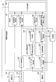
- FIG. 2 is a block diagram illustrating an example of a functional configuration of the information processing system 1 according to the present embodiment.
- the information processing system 1 includes an information processing apparatus 100, a depth sensor 210, an imaging unit 230, a storage unit 180, and a control memory 190.
- the depth sensor 210 and the imaging unit 230 correspond to the depth sensor 210 and the imaging unit 230 described above with reference to FIG.
- the storage unit 180 is a storage area for storing various data temporarily or permanently.
- the control memory 190 is a storage area for the information processing apparatus 100 to write various control information in order to control the operation of the depth sensor 210. That is, the depth sensor 210 switches an operation related to acquisition of information for distance estimation with an object in the real space based on control information (for example, a trigger or the like) written in the control memory 190. As a result, the information processing apparatus 100 can control the operation of the depth sensor 210 via the control memory 190.
- the information processing apparatus 100 includes a depth estimation unit 110, a self-position estimation unit 120, a determination unit 130, and a trigger generation unit 140.
- the depth estimation unit 110 acquires information corresponding to the detection result by the depth sensor 210 from the depth sensor 210, and estimates a distance between a predetermined viewpoint and an object located in the real space based on the acquired information.
- the depth estimation unit 110 can measure the distance to the subject (that is, the object) corresponding to the pixel according to the time measured for each pixel.
- the depth estimation unit 110 can measure the distance to the subject (that is, the object) for each pixel of the image sensor based on the change in the pattern obtained from the imaging result.
- the depth estimation unit 110 Based on the above configuration, the depth estimation unit 110 generates a depth map in which the estimation result of the distance between the predetermined viewpoint and the object located in the real space is mapped on the imaging plane, and the generated depth The map is output to the self-position estimation unit 120 (feature point extraction unit 122).
- the depth estimation unit 110 may output the generated depth map to the determination unit 130 (model shape determination unit 133) described later.
- the depth estimation unit 110 corresponds to an example of a “first estimation unit”.
- the self-position estimation unit 120 estimates at least one of the position and orientation of a predetermined target in real space. In this description, for convenience, the self-position estimation unit 120 estimates the position and orientation in real space of the moving body 200 in which the depth sensor 210 and the imaging unit 230 are held with respect to the housing illustrated in FIG. Shall.
- the self-position estimating unit 120 corresponds to an example of a “second estimating unit”.
- the self-position estimation unit 120 includes a corner point detection unit 121, a feature point extraction unit 122, a matching processing unit 123, a posture evaluation unit 124, a 3D model update unit 125, and a prediction unit. 126.
- the corner point detection unit 121 acquires an image captured by the imaging unit 230 (that is, an image in real space) from the imaging unit 230.
- the corner point detection unit 121 extracts, for example, texture information from the image by performing image analysis processing on the acquired image, and detects a corner point from the image based on the extracted texture information.
- the corner point corresponds to an intersection of a plurality of edges, in other words, it can be defined as a point where there are a plurality of distinct edges having different directions in the vicinity of a certain local area. Then, the corner point detection unit 121 outputs information indicating the detection result of the corner point from the acquired image to the feature point extraction unit 122.
- the feature point extraction unit 122 acquires a depth map from the depth estimation unit 110. In addition, the feature point extraction unit 122 acquires information indicating a corner point detection result from the corner point detection unit 121. The feature point extraction unit 122 extracts the information indicating the measurement result of the corresponding distance from the acquired depth map (in other words, depth information) and associates the detected corner points with each of the detected corner points. A feature point having accurate position information is defined. As described above, feature points are extracted from the image captured by the imaging unit 230. Then, the feature point extraction unit 122 outputs information indicating the feature point extraction result to the three-dimensional model update unit 125.
- the three-dimensional model update unit 125 acquires information indicating the feature point extraction result from the feature point extraction unit 122.
- the three-dimensional model update unit 125 integrates the extracted feature points into the three-dimensional space model based on the acquired information.
- the three-dimensional space model is a model that three-dimensionally reproduces the position, posture, shape, and the like of an object (real object) existing in the real space.
- the data integrated as a three-dimensional space model is held in the storage unit 180, for example.
- the three-dimensional model update unit 125 may acquire information indicating the estimation result of the position and posture of the moving body 200 in the real space from the posture evaluation unit 124 described later. In this case, the three-dimensional model update unit 125 may integrate the extracted feature points into the three-dimensional space model according to the position and orientation of the moving body 200 in the real space.
- a determination unit 130 (new) The area / new viewpoint determination unit 137) may be notified.
- the determination unit 130 determines whether information corresponding to the feature points newly integrated with the three-dimensional space model is included in the three-dimensional space model before integration. It becomes possible. Therefore, for example, the determination unit 130 determines whether or not the feature points have been extracted for a new region in which no feature points have been acquired in the past (hereinafter also referred to as “new region”), and whether or not new features have not been detected in the past. It is also possible to determine whether a correct viewpoint (hereinafter also referred to as “new viewpoint”) has been detected.
- the matching processing unit 123 and the posture evaluation unit 124 are based on the matching between the image captured by the imaging unit 230 and the three-dimensional space model stored in the storage unit 180, and the position of the moving body 200 in the real space. And a configuration for estimating the posture.
- the matching processing unit 123 acquires an image captured by the imaging unit 230 from the imaging unit 230. Based on information on tracking points (ie, feature points) included in the three-dimensional space model stored in the storage unit 180, the matching processing unit 123 determines the position on the image corresponding to the tracking points as the three-dimensional space. Calculation is performed based on matching between the model and the image. Then, the matching processing unit 123 outputs information indicating the matching result to the posture evaluation unit 124. The matching processing unit 123 may output information indicating the matching result to the determination unit 130 (feature point distribution determination unit 135) described later.
- the posture evaluation unit 124 estimates the position and posture of the imaging unit 230 (and eventually the moving body 200) in real space based on the result of the matching performed by the matching processing unit 123. Specifically, the posture evaluation unit 124, based on a predetermined algorithm, receives a pair of a tracking point three-dimensional position and a position on the image corresponding to the tracking point. Estimate position and orientation in real space. Examples of the algorithm include a PnP algorithm and an N-point algorithm.
- the posture evaluation unit 124 outputs information indicating the estimation result of the position and posture of the imaging unit 230 (and eventually the moving body 200) in the real space to the three-dimensional model update unit 125.
- the three-dimensional model update unit 125 may correct the three-dimensional position of the tracking point (that is, the feature point) included in the three-dimensional space model based on the estimation result.
- the prediction unit 126 refers to the three-dimensional space model (that is, the generated or updated three-dimensional space model) held in the storage unit 180, and sets the distribution of feature points (for example, points or surfaces) extracted in the past. Based on this, the depth information of the feature points predicted to be observed according to the current position and orientation of the imaging unit 230 (and thus the moving body 200) is extracted. Then, the prediction unit 126 outputs information indicating the extraction result of the depth information of the feature point to the determination unit 130 (model shape determination unit 133) described later as the prediction result of the depth information of the feature point.
- the determination unit 130 model shape determination unit 133
- the determination unit 130 determines various information related to the estimation of the position and orientation of the moving body 200 in the real space. For example, as illustrated in FIG. 2, the determination unit 130 includes at least one of an elapsed time determination unit 131, a model shape determination unit 133, a feature point distribution determination unit 135, and a new area / new viewpoint determination unit 137. May be included.
- the elapsed time determination unit 131 monitors the elapsed time (for example, the number of frames) after the depth sensor 210 (light projection unit 213) starts or ends the light projection, and the elapsed time is determined according to the monitoring result. It is determined whether or not the period has been exceeded. Then, the elapsed time determination unit 131 notifies the determination result to a trigger generation unit 140 described later.
- the elapsed time determination unit 131 when a period during which light projection is performed by the depth sensor 210 (hereinafter also referred to as “light projection period”) continues beyond a predetermined period, This is notified to the trigger generation unit 140.
- the elapsed time determination unit 131 generates a trigger when a period during which light is not projected by the depth sensor 210 (hereinafter also referred to as “light-out period”) exceeds a predetermined period. Notification to the unit 140.
- the model shape determination unit 133 acquires the prediction result of the depth information of the feature points predicted to be observed according to the current position and orientation of the moving body 200 from the prediction unit 126. Further, the model shape determination unit 133 acquires a depth map from the depth estimation unit 110. Note that the acquired depth map includes the depth information of each feature point actually observed according to the current position and orientation of the moving body 200. Then, the model shape determination unit 133 compares the acquired depth map (in other words, the actual observation result of the depth information of the feature point) with the prediction result of the depth information of the feature point that is predicted to be observed. Then, the trigger generation unit 140 is notified of the comparison result.
- the model shape determination unit 133 displays the observation result when the gap between the actual observation result of the depth information of the feature point and the prediction result of the depth information of the feature point exceeds a threshold value.
- the trigger generation unit 140 is notified that there is a gap between the prediction generation result and the prediction result.
- the feature point distribution determination unit 135 acquires information indicating a matching result between the image captured by the imaging unit 230 and the three-dimensional space model from the matching processing unit 123. Based on the matching result, the feature point distribution determination unit 135 determines the tracking state of the position and orientation of the imaging unit 230 (and thus the moving body 200) in the real space, and the trigger generation unit to be described later. 140 is notified.
- the feature point distribution determination unit 135 determines whether or not the number of feature points that have been successfully tracked is less than a threshold based on the result of the matching, and the determination result is used as a trigger generation unit. 140 may be notified. As another example, the feature point distribution determination unit 135 may evaluate the distribution of feature points that have been successfully tracked based on the matching result, and notify the trigger generation unit 140 of the evaluation result. . As a more specific example, the feature point distribution determination unit 135 generates information about a partial region in which the number of feature points is less than a threshold when the distribution of feature points that have been successfully tracked is biased. The unit 140 may be notified.
- the new area / new viewpoint determination unit 137 acquires information indicating the update result of the three-dimensional space model from the three-dimensional model update unit 125.
- the new area / new viewpoint determination unit 137 determines whether the feature point is extracted for the new area and whether a new viewpoint is detected according to the update result of the three-dimensional space model, and the determination result Is sent to a trigger generation unit 140 described later.
- FIG. 3 is an explanatory diagram for explaining a new area and a new viewpoint related to generation and update of a three-dimensional space model.
- spherical information divided into N equal parts is defined for a point group (or voxel volume) of one or more feature points included in the three-dimensional space model, and the position and orientation of the depth sensor 210 are defined.
- a flag is attached to an area where light is projected from the light projecting unit 213 in the spherical information.
- reference numerals 210a and 210b schematically indicate viewpoint positions indicating the relative position and orientation of the depth sensor 210 with respect to the spherical information defined as described above.
- the depth sensor 210 is positioned at the viewpoint position 210a, the light projected by the light projecting unit 213 of the depth sensor 210 is irradiated to the partial area to which the reference symbol R11 is attached in the spherical information. It becomes. That is, in this case, a flag is attached to the partial region R11.
- the depth sensor 210 when the depth sensor 210 is located at the viewpoint position 210b, the light projected by the light projecting unit 213 of the depth sensor 210 is irradiated to the partial area to which the reference symbol R13 is attached in the spherical information. It becomes. That is, in this case, a flag is attached to the partial region R13.
- the position and orientation of the depth sensor 210 have changed from the viewpoint position 210a to the viewpoint position 210b.
- the flag is not set in the partial region R13
- the feature point is not extracted from the partial region R13.
- the partial region R13 corresponds to a new region from which feature points have not been extracted
- the viewpoint position 210b corresponds to a newly detected new viewpoint.
- the trigger generation unit 140 controls the operation of the light projecting unit 213 of the depth sensor 210 via the control memory 190 according to various determination results by the determination unit 130. That is, the trigger generation unit 140 corresponds to an example of a “control unit”.
- the trigger generation unit 140 may switch the presence / absence of light projection by the light projecting unit 213 based on the determination result notified from the elapsed time determining unit 131. Specifically, the trigger generation unit 140 generates a trigger for limiting the light projection by the light projection unit 213 when the light projection period continues beyond a predetermined period, and the trigger is stored in the control memory. 190 is written. Similarly, when the extinguishing period continues beyond a predetermined period, the trigger generation unit 140 generates a trigger for starting light projection by the light projecting unit 213 and writes the trigger in the control memory 190. .
- the light projecting unit 213 intermittently projects light every predetermined period, and the power consumption is reduced compared to the case where the light projecting unit 213 continuously projects light. It can be kept low.
- the trigger generation unit 140 causes each of the plurality of light projecting units 213 (for example, the light projecting units 213 corresponding to the plurality of devices) to project light in a time-sharing manner. You may control the light projection timing of the optical part 213.
- the elapsed time determination unit 131 monitors the elapsed time after each depth sensor 210 (light projection unit 213) starts or ends the light projection, and the determination corresponding to each depth sensor 210 is performed. The result may be notified to the trigger generation unit 140. Accordingly, the trigger generation unit 140 can recognize the timing at which each depth sensor 210 projects light.
- the trigger generation unit 140 may limit light projection by the light projecting unit 213 based on the determination result notified from the model shape determining unit 133. Specifically, when the gap between the actual observation result of the depth information of the feature point and the prediction result of the depth information of the feature point exceeds the threshold, the trigger generation unit 140 projects the light projecting unit 213. The light may be projected on. In other cases, the trigger generation unit 140 may limit light projection by the light projecting unit 213. By such control, the opportunity for the light projecting unit 213 to project light is limited, so that power consumption can be reduced.
- the trigger generation unit 140 may limit light projection by the light projecting unit 213 based on the determination result notified from the feature point distribution determining unit 135. As a specific example, the trigger generation unit 140 may cause the light projecting unit 213 to project light when the number of feature points that have been successfully tracked is less than a threshold value. In other cases, the trigger generation unit 140 may limit light projection by the light projecting unit 213. By such control, the opportunity for the light projecting unit 213 to project light is limited, so that power consumption can be reduced.
- the trigger generation unit 140 performs limited light toward a partial region in which the number of feature points is less than a threshold value.
- the light projecting unit 213 may control the direction in which the light is projected and the irradiation range of the light. By such control, the amount of light projected by the light projecting unit 213 is limited, so that power consumption can be kept low.
- the trigger generation unit 140 may limit the light projection by the light projecting unit 213 based on the determination result notified from the new area / new viewpoint determination unit 137. As a specific example, the trigger generation unit 140 may cause the light projecting unit 213 to project light when a feature point is extracted for a new region or when a new viewpoint is detected. In other cases, the trigger generation unit 140 may limit light projection by the light projecting unit 213. By such control, the opportunity for the light projecting unit 213 to project light is limited, so that power consumption can be reduced.
- control related to the light projection by the light projecting unit 213 is merely an example, and the operation of the information processing apparatus 100 according to the present embodiment is not necessarily limited to the above-described example. That is, it is possible to control light projection by the light projecting unit 213 according to a situation that can be determined based on information that can be acquired in the process of estimating the position and orientation of the moving body 200 in real space. If so, the conditions for the determination and the contents of the control are not particularly limited.
- information obtained according to the distance (that is, the observation distance) between the moving body 200 (depth sensor 210) and a certain object in real space is different.
- information for example, information on feature points
- the moving body 200 and the target object are separated from each other, information (for example, information on feature points) can be acquired over the wide light projecting unit 213 area.
- the moving body 200 and the target object are located closer to each other, the area in the real space where information can be acquired is limited, but more detailed information about the target object is acquired. Is possible.
- information that has not been acquired due to the difference in observation distance for example, information on feature points
- the operation related to the light projection by the light projecting unit 213 may be controlled based on an instruction from the user via a predetermined input unit.
- the interval when the light projecting unit 213 projects light intermittently may be controlled based on an instruction from the user.
- the irradiation range of light projected from the light projecting unit 213 and the direction in which the light is projected may be controlled based on an instruction from the user. More specifically, when the information processing apparatus 100 receives a designation of ROI (Region of Interest) from the user, light is projected from the light projecting unit 213 toward an area in the real space corresponding to the ROI. As described above, the irradiation direction and irradiation range of the light may be controlled.
- ROI Region of Interest
- the configuration described above is merely an example, and the functional configuration of the information processing system 1 according to the present embodiment is not necessarily limited to the example illustrated in FIG.
- the information processing apparatus 100, the depth sensor 210, and the imaging unit 230 may be integrally configured.
- the storage unit 180 may be provided inside the information processing apparatus 100.
- some of the components of the information processing apparatus 100 may be provided outside the information processing apparatus 100.
- the depth estimation unit 110 may be provided on the depth sensor 210 side.
- some configurations of the self-position estimation unit 120, the determination unit 130, and the trigger generation unit 140 may be provided in another device such as a server.
- each function of the information processing apparatus 100 may be realized by cooperation of a plurality of apparatuses.
- FIGS. 4 and 5 are flowcharts illustrating an example of a flow of a series of processes of the information processing system 1 according to the present embodiment.
- the information processing apparatus 100 (matching processing unit 123) includes an image captured by the imaging unit 230 held in the moving body 200, a three-dimensional space model generated or updated in advance, Based on the matching between the positions, the position on the image corresponding to the tracking point is calculated (S101).
- the information processing apparatus 100 (posture evaluation unit 124) estimates the position and posture of the imaging unit 230 (and eventually the moving body 200) in real space based on the matching result (S103).
- the information processing apparatus 100 (three-dimensional model updating unit 125) corrects (optimizes) the three-dimensional position of the tracking point (that is, the feature point) included in the three-dimensional space model based on the estimation result. (S105).
- a trigger irradiation trigger
- the information processing apparatus 100 estimates the distance between the moving body 200 and an object located in the real space based on information corresponding to the detection result by the depth sensor 210, and the estimation result of the distance Generates a depth map mapped to the imaging plane.
- the information processing apparatus 100 corner point detection unit 121) extracts texture information from the image by performing image analysis processing on the image captured by the imaging unit 230 (that is, an image in real space). Then, a corner point is detected from the image based on the extracted texture information (S109).
- the information processing apparatus 100 extracts and associates information (in other words, depth information) indicating the measurement result of the corresponding distance from the acquired depth map with respect to each detected corner point.
- a feature point having three-dimensional position information is defined (S111).
- feature points are extracted from the image captured by the imaging unit 230.
- the information processing apparatus 100 three-dimensional model update unit 125
- the information processing apparatus 100 determines condition determination according to a predetermined situation relating to estimation of the position and orientation of the moving body 200 in the real space, and generates an irradiation trigger according to the determination result. (S200).
- the information processing apparatus 100 (elapsed time determination unit 131) monitors the elapsed time (for example, the number of frames) after the light projecting unit 213 of the depth sensor 210 starts or ends the light projection. It may be determined whether or not the elapsed time exceeds a predetermined period (S201).
- the information processing apparatus 100 determines the position and orientation of the moving body 200 in the real space based on the matching result between the image captured by the imaging unit 230 and the three-dimensional space model.
- the tracking state may be determined.
- the information processing apparatus 100 may determine whether or not the number of feature points that have been successfully tracked is less than a threshold value.
- the information processing apparatus 100 evaluates the distribution of feature points that have been successfully tracked, and if the distribution of feature points that have been successfully tracked is biased, the number of the feature points A partial region where is less than the threshold may be specified (S203).
- the information processing apparatus 100 determines whether or not the feature point has been extracted for the new region and whether or not a new viewpoint has been detected based on the update result of the three-dimensional space model. It may be done (S205).
- the information processing apparatus 100 refers to the three-dimensional space model and is observed according to the current position and orientation of the moving body 200 according to the distribution of feature points extracted in the past. Is extracted as the prediction result of the depth information (S207).
- the information processing apparatus 100 model shape determination unit 133) is observed with the depth map generated according to the current position and orientation of the moving body 200 (that is, the actual observation result of the depth information of the feature points).
- the prediction result of the depth information of the feature point that is predicted to be compared is compared. Thereby, the information processing apparatus 100 may determine whether or not the gap between the actual observation result of the depth information of the feature point and the prediction result of the depth information of the feature point exceeds a threshold value ( S209).
- the information processing apparatus 100 (the trigger generation unit 140) generates an irradiation trigger according to the above-described various determination results, and writes the generated irradiation trigger in the control memory 190, thereby projecting light by the light projecting unit 213.
- movement which concerns on is controlled (S211).
- the information processing apparatus 100 responds to a predetermined situation relating to the estimation of the position and orientation of the target apparatus (for example, the moving body 200) in the real space.
- the operation related to the light projection by the light projecting unit 213 is controlled.
- the information processing apparatus 100 controls, for example, a range in which light is projected by the light projecting unit 213 according to a situation (that is, an irradiation range), and thereby the amount of light to be projected. Can be limited. Further, the information processing apparatus 100 can also limit the trigger for light to be projected from the light projecting unit 213 according to the situation.
- the distance measurement range of the depth sensor 210 depends on the irradiation power of the light projected by the light projecting unit 213. Specifically, when the error amount in ranging is ⁇ L , the error amount ⁇ L is expressed by a relational expression shown as (Equation 1) below.
- the variable p corresponds to the amount of electrons emitted from the light projecting unit 213. Further, the amount of electrons depends on the irradiation power of light projected by the light projecting unit 213. From this, it can be seen that the error amount in distance measurement ⁇ depends on the irradiation power of the light projected by the light projecting unit 213.
- FIG. 6 is a diagram showing an example of a simulation result regarding the relationship between the average overhead power of the light projecting unit 213 and the error in distance measurement.
- the horizontal axis indicates the error (mm) in distance measurement
- the vertical axis indicates the average power (w) of the light source (that is, the light projecting unit 213).
- the higher the average power consumption of the light source the smaller the error that occurs in ranging.
- the shorter the pulse width of light projected from the light source that is, the shorter the interval of intermittent driving, the smaller the error that occurs in ranging.
- the power consumption is quadrupled by doubling the distance measurement accuracy, and the power consumption is quadrupled by doubling the distance measurement range.
- FIG. 7 is an explanatory diagram for explaining an example of conditions required for distance measurement according to the distance measurement range.
- the accuracy required when the distance measurement range is “1 m”, “5 m”, and “10 m” is shown.
- the distance measurement range when the distance measurement range is 1 m, an error of 0.5% or less is required as accuracy. As another example, when the distance measurement range is 5 m, an accuracy of 1.0% or less is required. As another example, when the distance measurement range is 10 m, the accuracy is required to be 5.0% or less.
- depth sensor according to the present embodiment corresponds to each use case illustrated in FIG. 7. Focusing on the case, it is summarized below.
- the estimated amount of power consumption is as shown in Table 1 below.
- Table 1 a minimum power consumption of 400 mW is required.
- the size of the target to be measured is about 50 cm, and the irradiation angle of light projected from the light source of the depth sensor according to the present embodiment is limited to 55 deg to 10 deg.
- FIG. 8 is a diagram showing an example of the relationship between the depth according to the irradiation angle of light and the irradiation range in the horizontal direction.
- the horizontal axis indicates the depth (m)
- the vertical axis indicates the irradiation range (m) in the horizontal direction.
- the depth corresponding to the irradiation angle and the horizontal irradiation range Shows the relationship.
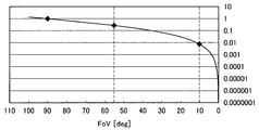
- FIG. 9 is a diagram showing an example of the relationship between the light irradiation angle and the power consumption.
- the irradiation angle is 90 degrees
- the relative change in power consumption according to the irradiation angle is shown. Shows an example of simulation results.
- the horizontal axis indicates the irradiation angle (deg)
- the vertical axis indicates the power consumption as a relative value.
- the power consumption can be limited to 1/35.
- the power consumption can be limited as shown in Table 2 below.
- the measurement is performed by limiting the irradiation angle (irradiation range) of the light projected from the light source of the depth sensor according to the situation. It is possible to suppress power consumption while maintaining distance accuracy.
- the information processing apparatus 100 detects a part such as a face, a hand, and a leg or a person itself as a target, and light is projected from the light projecting unit 213 toward a region where the target is detected.
- the irradiation direction and irradiation range of the light may be controlled.
- the information processing apparatus 100 detects a predetermined object from the image by performing image analysis on the image captured by the image capturing unit 230, and includes the image in which the object is detected. May be set as the ROI. In this case, the information processing apparatus 100 sets the irradiation direction and irradiation range of the light so that the light is partially projected from the light projecting unit 213 toward the real space region corresponding to the ROI. You may control.
- FIGS. 10 to 12 are explanatory diagrams for explaining the outline of the information processing system according to the modification, and show an example in which the irradiation range of light projected from the light projecting unit 213 is limited. Yes.
- FIG. 10 shows an example when a user's hand is detected as an object.
- the information processing apparatus 100 sets the region where the user's hand U211 is detected as the ROI, and the light is partially transmitted from the light projecting unit 213 toward the partial region R211 in the real space corresponding to the ROI.
- the irradiation direction and irradiation range of the light may be controlled so that the light is projected.
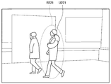
- FIG. 11 shows an example when a person (that is, the whole image of a person) is detected as an object.
- the information processing apparatus 100 sets an area where the person U221 is detected as an ROI, and partially projects light from the light projecting unit 213 toward the partial area R221 in the real space corresponding to the ROI.
- the irradiation direction and irradiation range of the light may be controlled so that the light is emitted.
- FIG. 12 shows an example when a user's face is detected as an object.
- an example in which a plurality of objects (that is, the user's face) is detected is illustrated.
- the faces U231 and U233 of each of the two users are detected.
- the information processing apparatus 100 individually sets the areas where the faces U231 and U233 are detected as ROIs, and sets the partial areas in the real space corresponding to the ROIs (that is, the partial areas R231 and R233).
- the irradiation direction and irradiation range of the light may be controlled so that the light is individually projected from the light projecting unit 213.
- a plurality of light sources arranged on the array as the light projecting unit 213 is used. May be provided.
- the information processing apparatus 100 individually controls the irradiation direction and the irradiation range of the light projected from each light source, so that light is directed toward each of the partial regions R231 and R233 corresponding to each ROI. May be controlled so that each is individually projected.
- the light projected from the light projecting unit 213 is dispersed by a plurality of movable mirrors using MEMS technology, so that light is directed toward each of the partial regions R231 and R233 corresponding to each ROI. You may control so that it may light separately.
- the movable mirror may be disposed inside the light projecting unit 213.
- FIG. 13 is a functional block diagram illustrating a configuration example of the hardware configuration of the information processing apparatus configuring the information processing system according to an embodiment of the present disclosure.
- the information processing apparatus 900 constituting the information processing system according to the present embodiment mainly includes a CPU 901, a ROM 902, and a RAM 903.
- the information processing apparatus 900 further includes a host bus 907, a bridge 909, an external bus 911, an interface 913, an input device 915, an output device 917, a storage device 919, a drive 921, and a connection port 923. And a communication device 925.
- the CPU 901 functions as an arithmetic processing unit and a control unit, and controls all or a part of the operation in the information processing apparatus 900 according to various programs recorded in the ROM 902, the RAM 903, the storage apparatus 919, or the removable recording medium 927.
- the ROM 902 stores programs used by the CPU 901, calculation parameters, and the like.
- the RAM 903 primarily stores programs used by the CPU 901, parameters that change as appropriate during execution of the programs, and the like. These are connected to each other by a host bus 907 constituted by an internal bus such as a CPU bus.
- a host bus 907 constituted by an internal bus such as a CPU bus.
- the host bus 907 is connected to an external bus 911 such as a PCI (Peripheral Component Interconnect / Interface) bus via a bridge 909.
- an input device 915, an output device 917, a storage device 919, a drive 921, a connection port 923, and a communication device 925 are connected to the external bus 911 via an interface 913.
- the input device 915 is an operation means operated by the user, such as a mouse, a keyboard, a touch panel, a button, a switch, a lever, and a pedal. Further, the input device 915 may be, for example, remote control means (so-called remote control) using infrared rays or other radio waves, or an external connection device such as a mobile phone or a PDA corresponding to the operation of the information processing device 900. 929 may be used. Furthermore, the input device 915 includes an input control circuit that generates an input signal based on information input by a user using the above-described operation means and outputs the input signal to the CPU 901, for example. A user of the information processing apparatus 900 can input various data and instruct a processing operation to the information processing apparatus 900 by operating the input device 915.
- the output device 917 is a device that can notify the user of the acquired information visually or audibly. Examples of such devices include CRT display devices, liquid crystal display devices, plasma display devices, EL display devices, display devices such as lamps, audio output devices such as speakers and headphones, printer devices, and the like.
- the output device 917 outputs results obtained by various processes performed by the information processing apparatus 900. Specifically, the display device displays results obtained by various processes performed by the information processing device 900 as text or images.
- the audio output device converts an audio signal composed of reproduced audio data, acoustic data, and the like into an analog signal and outputs the analog signal.
- the storage device 919 is a data storage device configured as an example of a storage unit of the information processing device 900.
- the storage device 919 includes, for example, a magnetic storage device such as an HDD (Hard Disk Drive), a semiconductor storage device, an optical storage device, or a magneto-optical storage device.
- the storage device 919 stores programs executed by the CPU 901 and various data.
- the drive 921 is a reader / writer for a recording medium, and is built in or externally attached to the information processing apparatus 900.
- the drive 921 reads information recorded on a removable recording medium 927 such as a mounted magnetic disk, optical disk, magneto-optical disk, or semiconductor memory, and outputs the information to the RAM 903.
- the drive 921 can also write a record to a removable recording medium 927 such as a magnetic disk, an optical disk, a magneto-optical disk, or a semiconductor memory that is mounted.
- the removable recording medium 927 is, for example, a DVD medium, an HD-DVD medium, a Blu-ray (registered trademark) medium, or the like.
- the removable recording medium 927 may be a compact flash (registered trademark) (CF: CompactFlash), a flash memory, an SD memory card (Secure Digital memory card), or the like. Further, the removable recording medium 927 may be, for example, an IC card (Integrated Circuit card) on which a non-contact IC chip is mounted, an electronic device, or the like.
- CF CompactFlash
- SD memory card Secure Digital memory card
- the connection port 923 is a port for directly connecting to the information processing apparatus 900.
- Examples of the connection port 923 include a USB (Universal Serial Bus) port, an IEEE 1394 port, a SCSI (Small Computer System Interface) port, and the like.
- As another example of the connection port 923 there are an RS-232C port, an optical audio terminal, an HDMI (registered trademark) (High-Definition Multimedia Interface) port, and the like.
- the communication device 925 is a communication interface configured with, for example, a communication device for connecting to a communication network (network) 931.
- the communication device 925 is, for example, a communication card for wired or wireless LAN (Local Area Network), Bluetooth (registered trademark), or WUSB (Wireless USB).
- the communication device 925 may be a router for optical communication, a router for ADSL (Asymmetric Digital Subscriber Line), a modem for various communication, or the like.
- the communication device 925 can transmit and receive signals and the like according to a predetermined protocol such as TCP / IP, for example, with the Internet or other communication devices.
- the communication network 931 connected to the communication device 925 is configured by a wired or wireless network, and may be, for example, the Internet, a home LAN, infrared communication, radio wave communication, satellite communication, or the like. .
- a computer program for realizing each function of the information processing apparatus 900 constituting the information processing system according to the present embodiment as described above can be produced and mounted on a personal computer or the like.
- a computer-readable recording medium storing such a computer program can be provided.
- the recording medium is, for example, a magnetic disk, an optical disk, a magneto-optical disk, a flash memory, or the like.
- the above computer program may be distributed via a network, for example, without using a recording medium.
- the number of computers that execute the computer program is not particularly limited.
- the computer program may be executed by a plurality of computers (for example, a plurality of servers) in cooperation with each other.
- the information processing apparatus 100 detects light reflected from the predetermined light projecting unit 213 toward the object in the real space. Based on the result, the distance between a predetermined viewpoint (in other words, the moving body 200 shown in FIG. 1) and the object is estimated. Further, the information processing apparatus 100 estimates at least one of the position and orientation of the predetermined viewpoint in the real space based on the estimation result of the distance. Then, the information processing apparatus 100 controls the light projected from the light projecting unit 213 in accordance with a situation regarding estimation of at least one of the position and orientation of the predetermined viewpoint.
- the information processing apparatus 100 may limit a period during which light is projected from the light projecting unit 213 according to the situation. As another example, the information processing apparatus 100 may limit the irradiation range of light projected from the light projecting unit 213 according to the situation.
- the information processing system 1 According to the configuration as described above, according to the information processing system 1 according to the present embodiment, even when the active irradiation method is used for estimating the distance to the target object, the accuracy related to the estimation is maintained. However, power consumption can be further reduced. That is, according to the information processing system according to the present embodiment, when the active irradiation method is employed, it is possible to achieve both stabilization of distance estimation with the target object and suppression of power consumption. Become.
- a first estimation unit configured to estimate a distance between a predetermined viewpoint and the object based on a detection result of light projected from the predetermined light projecting unit toward an object in real space and reflected by the object;
- a second estimation unit that estimates at least one of a position and a posture of the predetermined viewpoint in real space based on the estimation result of the distance;
- a control unit that controls the light projected from the light projecting unit according to a situation regarding estimation of at least one of the position and the posture;
- An information processing apparatus comprising: (2) The information processing apparatus according to (1), wherein the control unit limits a period during which the light is projected from the light projecting unit according to the situation.
- the information processing apparatus controls a period in which the light is projected by controlling the light to be projected intermittently from the light projecting unit.
- the control unit limits an irradiation range of the light projected from the light projecting unit according to the situation.
- the second estimation unit is based on the image captured by the imaging unit held at the predetermined viewpoint and the estimation result of the distance, and at least of the position and orientation of the predetermined viewpoint in real space.
- the second estimation unit extracts a feature point from the image, estimates at least one of the position and the posture based on the extraction result of the feature point,
- the control unit controls the light projected from the light projecting unit according to the extraction result of the feature points.
- the information processing apparatus according to (5).
- the control unit projects the light from the light projecting unit when the number of the feature points tracked according to a change in at least one of the position and the posture is less than a threshold value.
- the control unit may target the light from the light projecting unit to at least a partial region in which the number of the feature points to be tracked is less than a threshold among regions where the image is captured by the imaging unit.
- the information processing apparatus includes Generating or updating a three-dimensional space model in which the environment around the predetermined viewpoint is three-dimensionally restored based on the extraction result of the feature points; Based on the feature points newly extracted from the image and the three-dimensional space model generated or updated in the past, at least one of the position and the posture is estimated, The controller is Controlling the light projected from the light projecting unit based on the feature point newly extracted from the image and the three-dimensional space model generated or updated in the past, The information processing apparatus according to any one of (6) to (8).
- the control unit when information corresponding to the feature point extracted from the newly captured image is not included in the three-dimensional space model generated or updated in the past, from the light projecting unit The information processing apparatus according to (9), wherein the control is performed so that light is projected.
- the controller is At least one of the current position and the posture of the predetermined viewpoint estimated based on the newly captured image; At least one of the position and the posture estimated in the past with respect to the predetermined viewpoint based on the three-dimensional space model; Controlling the light projected from the light projecting unit based on the comparison result of The information processing apparatus according to (9).
- the control unit is configured to estimate the position of the feature point extracted from the newly captured image in the real space and the actual feature point according to the three-dimensional space model generated or updated in the past.
- the information processing apparatus according to (9), wherein the light is projected from the light projecting unit when the difference between the prediction result of the position in space and a threshold value is greater than or equal to a threshold value.
- the control unit limits an irradiation range of the light so that the light is projected toward the target when a predetermined target is captured as the object in the image.
- the information processing apparatus according to any one of 5) to (12).
- the light projecting unit and the imaging unit are held in a predetermined housing, The information processing apparatus according to any one of (5) to (13), wherein the second estimation unit estimates at least one of a position and a posture of the housing in real space. (15) The information processing apparatus according to any one of (5) to (14), wherein the first estimation unit estimates the distance based on an imaging result of the light by the imaging unit. (16) When there are a plurality of light projecting units, the control unit projects the light by each of the plurality of light projecting units so that the light is projected in a time-sharing manner from each of the plurality of light projecting units. The information processing apparatus according to any one of (5) to (15), wherein the timing is controlled.
- Information processing apparatus 110 Depth estimation part 120 Self-position estimation part 121 Corner point detection part 122 Feature point extraction part 123 Matching process part 124 Posture evaluation part 125 Dimensional model update part 126 Prediction part 130 Determination part 131 Elapsed time determination Unit 133 model shape determination unit 135 feature point distribution determination unit 137 new viewpoint determination unit 140 trigger generation unit 180 storage unit 190 control memory 200 moving body 210 depth sensor 211 detection unit 213 light projecting unit 230 imaging unit
Landscapes
- Engineering & Computer Science (AREA)
- Physics & Mathematics (AREA)
- General Physics & Mathematics (AREA)
- Theoretical Computer Science (AREA)
- Computer Vision & Pattern Recognition (AREA)
- Radar, Positioning & Navigation (AREA)
- Remote Sensing (AREA)
- Computer Networks & Wireless Communication (AREA)
- Electromagnetism (AREA)
- Multimedia (AREA)
- Geometry (AREA)
- Computer Graphics (AREA)
- Software Systems (AREA)
- Optics & Photonics (AREA)
- Signal Processing (AREA)
- Length Measuring Devices By Optical Means (AREA)
- Automatic Focus Adjustment (AREA)
- Studio Devices (AREA)
- Optical Radar Systems And Details Thereof (AREA)
- Image Analysis (AREA)
- Measurement Of Optical Distance (AREA)
Abstract
Priority Applications (3)
| Application Number | Priority Date | Filing Date | Title |
|---|---|---|---|
| EP18806584.1A EP3633407A4 (fr) | 2017-05-24 | 2018-03-26 | Appareil de traitement d'informations, procédé de traitement d'informations et programme |
| US16/608,522 US11232590B2 (en) | 2017-05-24 | 2018-03-26 | Information processing apparatus, information processing method, and program |
| JP2019519494A JP7103354B2 (ja) | 2017-05-24 | 2018-03-26 | 情報処理装置、情報処理方法、及びプログラム |
Applications Claiming Priority (2)
| Application Number | Priority Date | Filing Date | Title |
|---|---|---|---|
| JP2017102489 | 2017-05-24 | ||
| JP2017-102489 | 2017-05-24 |
Publications (1)
| Publication Number | Publication Date |
|---|---|
| WO2018216342A1 true WO2018216342A1 (fr) | 2018-11-29 |
Family
ID=64395443
Family Applications (1)
| Application Number | Title | Priority Date | Filing Date |
|---|---|---|---|
| PCT/JP2018/012018 WO2018216342A1 (fr) | 2017-05-24 | 2018-03-26 | Appareil de traitement d'informations, procédé de traitement d'informations et programme |
Country Status (4)
| Country | Link |
|---|---|
| US (1) | US11232590B2 (fr) |
| EP (1) | EP3633407A4 (fr) |
| JP (1) | JP7103354B2 (fr) |
| WO (1) | WO2018216342A1 (fr) |
Cited By (2)
| Publication number | Priority date | Publication date | Assignee | Title |
|---|---|---|---|---|
| WO2020195877A1 (fr) * | 2019-03-25 | 2020-10-01 | ソニー株式会社 | Système médical, dispositif de traitement du signal et procédé de traitement du signal |
| WO2021117595A1 (fr) * | 2019-12-13 | 2021-06-17 | ソニーグループ株式会社 | Dispositif de traitement d'informations, procédé de traitement d'informations et programme |
Families Citing this family (2)
| Publication number | Priority date | Publication date | Assignee | Title |
|---|---|---|---|---|
| KR102596053B1 (ko) * | 2018-08-27 | 2023-11-01 | 엘지이노텍 주식회사 | 영상 처리 장치 및 영상 처리 방법 |
| CN114080535A (zh) * | 2019-06-28 | 2022-02-22 | 佳能株式会社 | 测量设备、摄像设备、测量系统、控制方法以及程序 |
Citations (6)
| Publication number | Priority date | Publication date | Assignee | Title |
|---|---|---|---|---|
| JPH11160016A (ja) * | 1997-11-26 | 1999-06-18 | Fuji Xerox Co Ltd | 距離測定方法及び装置 |
| JP2003194962A (ja) | 2001-12-27 | 2003-07-09 | Sunx Ltd | 光電センサ |
| WO2007069726A1 (fr) * | 2005-12-16 | 2007-06-21 | Ihi Corporation | Procede et dispositif d'identification d'auto-positionnement, et procede et dispositif de mesure de forme tridimensionnelle |
| US20140240469A1 (en) * | 2013-02-28 | 2014-08-28 | Motorola Mobility Llc | Electronic Device with Multiview Image Capture and Depth Sensing |
| WO2016163227A1 (fr) * | 2015-04-06 | 2016-10-13 | ソニー株式会社 | Dispositif et procédé de commande, et programme |
| WO2016181687A1 (fr) * | 2015-05-14 | 2016-11-17 | ソニー株式会社 | Dispositif de traitement d'image, procédé de traitement d'image et programme |
Family Cites Families (36)
| Publication number | Priority date | Publication date | Assignee | Title |
|---|---|---|---|---|
| NO302055B1 (no) * | 1993-05-24 | 1998-01-12 | Metronor As | Fremgangsmåte og system for geometrimåling |
| JP3647376B2 (ja) * | 2001-01-31 | 2005-05-11 | キヤノン株式会社 | 視点位置検出装置、視点位置検出方法及び立体画像表示システム |
| JP4573085B2 (ja) * | 2001-08-10 | 2010-11-04 | 日本電気株式会社 | 位置姿勢認識装置とその位置姿勢認識方法、及び位置姿勢認識プログラム |
| JP2004312249A (ja) * | 2003-04-04 | 2004-11-04 | Olympus Corp | カメラ |
| CN1836184A (zh) * | 2003-08-21 | 2006-09-20 | 柯尼卡美能达精密光学株式会社 | 图像拾取装置 |
| JP4427389B2 (ja) * | 2004-06-10 | 2010-03-03 | 株式会社トプコン | 測量機 |
| JP5175562B2 (ja) * | 2008-01-28 | 2013-04-03 | シャープ株式会社 | 人物位置検出装置および空気調和機 |
| JP5150310B2 (ja) * | 2008-03-04 | 2013-02-20 | 株式会社トプコン | 地理データ収集装置 |
| US8659658B2 (en) * | 2010-02-09 | 2014-02-25 | Microsoft Corporation | Physical interaction zone for gesture-based user interfaces |
| US8934766B2 (en) * | 2010-05-25 | 2015-01-13 | Canon Kabushiki Kaisha | Image pickup apparatus |
| JP5624394B2 (ja) * | 2010-07-16 | 2014-11-12 | キヤノン株式会社 | 位置姿勢計測装置、その計測処理方法及びプログラム |
| JP5587137B2 (ja) * | 2010-10-29 | 2014-09-10 | キヤノン株式会社 | 測定装置及び測定方法 |
| KR101694797B1 (ko) * | 2010-12-21 | 2017-01-11 | 삼성전자주식회사 | 3차원 이미지 센서의 구동 방법 |
| JP5738005B2 (ja) * | 2011-03-01 | 2015-06-17 | 株式会社トプコン | 光波距離測定装置 |
| JP5738080B2 (ja) * | 2011-06-09 | 2015-06-17 | キヤノン株式会社 | 撮像装置及びその制御方法 |
| TWI575494B (zh) * | 2011-08-19 | 2017-03-21 | 半導體能源研究所股份有限公司 | 半導體裝置的驅動方法 |
| US9117281B2 (en) * | 2011-11-02 | 2015-08-25 | Microsoft Corporation | Surface segmentation from RGB and depth images |
| JP5895305B2 (ja) * | 2011-12-06 | 2016-03-30 | シーシーエス株式会社 | 検査用照明装置及び検査用照明方法 |
| JP2013126165A (ja) * | 2011-12-15 | 2013-06-24 | Fujitsu Ltd | 撮像装置、撮像方法及びプログラム |
| US9109888B2 (en) * | 2012-03-21 | 2015-08-18 | Honda Motor Co., Ltd. | Distance measuring system |
| US9398229B2 (en) * | 2012-06-18 | 2016-07-19 | Microsoft Technology Licensing, Llc | Selective illumination of a region within a field of view |
| US10067231B2 (en) * | 2012-10-05 | 2018-09-04 | Faro Technologies, Inc. | Registration calculation of three-dimensional scanner data performed between scans based on measurements by two-dimensional scanner |
| US20140139632A1 (en) * | 2012-11-21 | 2014-05-22 | Lsi Corporation | Depth imaging method and apparatus with adaptive illumination of an object of interest |
| US9041914B2 (en) * | 2013-03-15 | 2015-05-26 | Faro Technologies, Inc. | Three-dimensional coordinate scanner and method of operation |
| JP6316568B2 (ja) * | 2013-10-31 | 2018-04-25 | 株式会社トプコン | 測量システム |
| RU2628420C1 (ru) * | 2014-02-24 | 2017-08-16 | Ниссан Мотор Ко., Лтд. | Устройство вычисления собственного местоположения и способ вычисления собственного местоположения |
| CN104881860B (zh) * | 2014-02-28 | 2019-01-08 | 国际商业机器公司 | 基于照片进行定位的方法和装置 |
| GB201407270D0 (en) * | 2014-04-24 | 2014-06-11 | Cathx Res Ltd | 3D data in underwater surveys |
| GB2529846B (en) * | 2014-09-03 | 2019-02-20 | Dyson Technology Ltd | Illumination Control of a Vision System for a Mobile Robot |
| JP6520053B2 (ja) * | 2014-11-06 | 2019-05-29 | 株式会社デンソー | 光飛行型測距装置 |
| US10122449B2 (en) * | 2014-12-01 | 2018-11-06 | Infineon Technologies Ag | Access control devices and a transceiver device |
| JP6584226B2 (ja) * | 2015-08-26 | 2019-10-02 | 株式会社トプコン | 測定装置 |
| JP6775969B2 (ja) * | 2016-02-29 | 2020-10-28 | キヤノン株式会社 | 情報処理装置、情報処理方法、及びプログラム |
| WO2018042801A1 (fr) * | 2016-09-01 | 2018-03-08 | ソニーセミコンダクタソリューションズ株式会社 | Dispositif d'imagerie |
| WO2018151226A1 (fr) * | 2017-02-15 | 2018-08-23 | パイオニア株式会社 | Dispositif de balayage optique et procédé de commande |
| US10627518B2 (en) * | 2017-06-02 | 2020-04-21 | Pixart Imaging Inc | Tracking device with improved work surface adaptability |
-
2018
- 2018-03-26 JP JP2019519494A patent/JP7103354B2/ja active Active
- 2018-03-26 WO PCT/JP2018/012018 patent/WO2018216342A1/fr active Application Filing
- 2018-03-26 US US16/608,522 patent/US11232590B2/en active Active
- 2018-03-26 EP EP18806584.1A patent/EP3633407A4/fr active Pending
Patent Citations (6)
| Publication number | Priority date | Publication date | Assignee | Title |
|---|---|---|---|---|
| JPH11160016A (ja) * | 1997-11-26 | 1999-06-18 | Fuji Xerox Co Ltd | 距離測定方法及び装置 |
| JP2003194962A (ja) | 2001-12-27 | 2003-07-09 | Sunx Ltd | 光電センサ |
| WO2007069726A1 (fr) * | 2005-12-16 | 2007-06-21 | Ihi Corporation | Procede et dispositif d'identification d'auto-positionnement, et procede et dispositif de mesure de forme tridimensionnelle |
| US20140240469A1 (en) * | 2013-02-28 | 2014-08-28 | Motorola Mobility Llc | Electronic Device with Multiview Image Capture and Depth Sensing |
| WO2016163227A1 (fr) * | 2015-04-06 | 2016-10-13 | ソニー株式会社 | Dispositif et procédé de commande, et programme |
| WO2016181687A1 (fr) * | 2015-05-14 | 2016-11-17 | ソニー株式会社 | Dispositif de traitement d'image, procédé de traitement d'image et programme |
Non-Patent Citations (1)
| Title |
|---|
| See also references of EP3633407A4 |
Cited By (2)
| Publication number | Priority date | Publication date | Assignee | Title |
|---|---|---|---|---|
| WO2020195877A1 (fr) * | 2019-03-25 | 2020-10-01 | ソニー株式会社 | Système médical, dispositif de traitement du signal et procédé de traitement du signal |
| WO2021117595A1 (fr) * | 2019-12-13 | 2021-06-17 | ソニーグループ株式会社 | Dispositif de traitement d'informations, procédé de traitement d'informations et programme |
Also Published As
| Publication number | Publication date |
|---|---|
| US20210110574A1 (en) | 2021-04-15 |
| US11232590B2 (en) | 2022-01-25 |
| EP3633407A4 (fr) | 2020-06-10 |
| JP7103354B2 (ja) | 2022-07-20 |
| JPWO2018216342A1 (ja) | 2020-05-28 |
| EP3633407A1 (fr) | 2020-04-08 |
Similar Documents
| Publication | Publication Date | Title |
|---|---|---|
| KR101950641B1 (ko) | 향상된 안구 추적을 위한 장면 분석 | |
| CN110310329B (zh) | 操作显示设备的方法、信息处理系统及非暂时性存储介质 | |
| US10852847B2 (en) | Controller tracking for multiple degrees of freedom | |
| JP6228320B2 (ja) | 制約なしslam用のセンサベースのカメラ運動検出 | |
| US10529074B2 (en) | Camera pose and plane estimation using active markers and a dynamic vision sensor | |
| JP2024045273A (ja) | 非制約環境において人間の視線及びジェスチャを検出するシステムと方法 | |
| WO2018216342A1 (fr) | Appareil de traitement d'informations, procédé de traitement d'informations et programme | |
| CN110915208A (zh) | 使用深度传感器的虚拟现实环境边界 | |
| US10169880B2 (en) | Information processing apparatus, information processing method, and program | |
| CN109564467B (zh) | 具有音频、视觉和运动分析的数码相机 | |
| US10890600B2 (en) | Real-time visual-inertial motion tracking fault detection | |
| KR20170014491A (ko) | 움직임 인식 방법 및 움직임 인식 장치 | |
| WO2018223153A1 (fr) | Système et procédé de détection de profondeur stéréoscopique active | |
| WO2019021569A1 (fr) | Dispositif de traitement d'informations, procédé de traitement d'informations et programme | |
| US10679376B2 (en) | Determining a pose of a handheld object | |
| JP2015118442A (ja) | 情報処理装置、情報処理方法およびプログラム | |
| WO2021016051A1 (fr) | Reconstruction conjointe d'environnement et étalonnage de caméra | |
| US20200211275A1 (en) | Information processing device, information processing method, and recording medium | |
| US20230300290A1 (en) | Information display system, information display method, and non-transitory recording medium | |
| US20220030206A1 (en) | Information processing apparatus, information processing method, program, and projection system | |
| US20230326056A1 (en) | Information processing apparatus, information processing method, and program | |
| CN112711324B (zh) | 基于tof相机的手势交互方法及其系统 | |
| TWI460683B (zh) | The way to track the immediate movement of the head | |
| KR20240007245A (ko) | 증강 현실 안내식 깊이 추정 |
Legal Events
| Date | Code | Title | Description |
|---|---|---|---|
| 121 | Ep: the epo has been informed by wipo that ep was designated in this application |
Ref document number: 18806584 Country of ref document: EP Kind code of ref document: A1 |
|
| ENP | Entry into the national phase |
Ref document number: 2019519494 Country of ref document: JP Kind code of ref document: A |
|
| NENP | Non-entry into the national phase |
Ref country code: DE |
|
| WWE | Wipo information: entry into national phase |
Ref document number: 2018806584 Country of ref document: EP |
|
| ENP | Entry into the national phase |
Ref document number: 2018806584 Country of ref document: EP Effective date: 20200102 |