WO2018216293A1 - 内燃機関の制御装置 - Google Patents
内燃機関の制御装置 Download PDFInfo
- Publication number
- WO2018216293A1 WO2018216293A1 PCT/JP2018/007441 JP2018007441W WO2018216293A1 WO 2018216293 A1 WO2018216293 A1 WO 2018216293A1 JP 2018007441 W JP2018007441 W JP 2018007441W WO 2018216293 A1 WO2018216293 A1 WO 2018216293A1
- Authority
- WO
- WIPO (PCT)
- Prior art keywords
- opening
- closing timing
- valve
- exhaust
- timing
- Prior art date
- Legal status (The legal status is an assumption and is not a legal conclusion. Google has not performed a legal analysis and makes no representation as to the accuracy of the status listed.)
- Ceased
Links
Images




Classifications
-
- F—MECHANICAL ENGINEERING; LIGHTING; HEATING; WEAPONS; BLASTING
- F01—MACHINES OR ENGINES IN GENERAL; ENGINE PLANTS IN GENERAL; STEAM ENGINES
- F01L—CYCLICALLY OPERATING VALVES FOR MACHINES OR ENGINES
- F01L1/00—Valve-gear or valve arrangements, e.g. lift-valve gear
- F01L1/34—Valve-gear or valve arrangements, e.g. lift-valve gear characterised by the provision of means for changing the timing of the valves without changing the duration of opening and without affecting the magnitude of the valve lift
- F01L1/344—Valve-gear or valve arrangements, e.g. lift-valve gear characterised by the provision of means for changing the timing of the valves without changing the duration of opening and without affecting the magnitude of the valve lift changing the angular relationship between crankshaft and camshaft, e.g. using helicoidal gear
- F01L1/352—Valve-gear or valve arrangements, e.g. lift-valve gear characterised by the provision of means for changing the timing of the valves without changing the duration of opening and without affecting the magnitude of the valve lift changing the angular relationship between crankshaft and camshaft, e.g. using helicoidal gear using bevel or epicyclic gear
-
- F—MECHANICAL ENGINEERING; LIGHTING; HEATING; WEAPONS; BLASTING
- F02—COMBUSTION ENGINES; HOT-GAS OR COMBUSTION-PRODUCT ENGINE PLANTS
- F02D—CONTROLLING COMBUSTION ENGINES
- F02D13/00—Controlling the engine output power by varying inlet or exhaust valve operating characteristics, e.g. timing
- F02D13/02—Controlling the engine output power by varying inlet or exhaust valve operating characteristics, e.g. timing during engine operation
-
- F—MECHANICAL ENGINEERING; LIGHTING; HEATING; WEAPONS; BLASTING
- F02—COMBUSTION ENGINES; HOT-GAS OR COMBUSTION-PRODUCT ENGINE PLANTS
- F02N—STARTING OF COMBUSTION ENGINES; STARTING AIDS FOR SUCH ENGINES, NOT OTHERWISE PROVIDED FOR
- F02N11/00—Starting of engines by means of electric motors
- F02N11/08—Circuits specially adapted for starting of engines
-
- Y—GENERAL TAGGING OF NEW TECHNOLOGICAL DEVELOPMENTS; GENERAL TAGGING OF CROSS-SECTIONAL TECHNOLOGIES SPANNING OVER SEVERAL SECTIONS OF THE IPC; TECHNICAL SUBJECTS COVERED BY FORMER USPC CROSS-REFERENCE ART COLLECTIONS [XRACs] AND DIGESTS
- Y02—TECHNOLOGIES OR APPLICATIONS FOR MITIGATION OR ADAPTATION AGAINST CLIMATE CHANGE
- Y02T—CLIMATE CHANGE MITIGATION TECHNOLOGIES RELATED TO TRANSPORTATION
- Y02T10/00—Road transport of goods or passengers
- Y02T10/10—Internal combustion engine [ICE] based vehicles
- Y02T10/12—Improving ICE efficiencies
Definitions
- the present invention relates to a control device for an internal combustion engine.
- Patent Document 1 describes a technology that includes a valve timing adjustment mechanism that controls the opening / closing timing of an intake valve of an internal combustion engine, and that sets the opening / closing timing to the most retarded timing to keep the pressure in the combustion chamber low when the internal combustion engine is started. Has been.
- Patent Document 2 includes a valve opening / closing timing control mechanism in an intake valve or an exhaust valve of an internal combustion engine, and the valve opening / closing timing control mechanism is set to a most retarded phase state, thereby compressing an air-fuel mixture in a combustion chamber.
- a technique is described in which the ratio is reduced (so-called decompression state) and the compression ratio of the air-fuel mixture in the combustion chamber is reduced to reduce engine vibration.
- Patent Document 2 describes a control mode in which the internal combustion engine is stopped by setting the valve opening / closing timing control mechanism to the most retarded phase while the idle stop condition is satisfied.
- Patent Documents 1 and 2 set the valve opening / closing timing control mechanism that controls the opening / closing timing of the intake valve to the most retarded phase, thereby reducing the compression ratio of air in the combustion chamber during cranking. It is intended to reduce the speed of crankshaft rotation.
- the area where the compression ratio of air in the combustion chamber can be reduced during cranking is only the process from the bottom dead center to the top dead center when the valve opening / closing timing control mechanism is set to the most retarded phase. I was able to imagine increasing the negative pressure and increasing the load in the process until the piston reaches the bottom dead center because the intake air amount decreases.
- a feature of the present invention is that a plurality of cylinders having a piston that reciprocates in a cylinder in association with rotation of a crankshaft, and an intake valve and an exhaust valve that open and close a combustion chamber in association with rotation of the crankshaft,
- An internal combustion engine comprising: a starter motor that drives and rotates a crankshaft; and a valve opening / closing timing control mechanism that sets an opening / closing timing of the exhaust valve by driving an electric actuator;
- EVO which is the opening timing of the exhaust valve
- EVC which is the closing timing of the exhaust valve
- the electric actuator is controlled based on the combustion speed in the combustion chamber. May be.
- the exhaust valve is opened and closed at the optimum timing corresponding to the combustion speed in the combustion chamber It becomes possible to control.
- FIG. 3 is a sectional view taken along line III-III in FIG. 2.
- FIG. 4 is a sectional view taken along line IV-IV in FIG. 2.
- an intake-side valve opening / closing timing control mechanism VTa for setting an opening / closing timing of an intake valve Va of an engine E as an internal combustion engine
- an exhaust-side valve opening / closing timing control for setting an opening / closing timing of an exhaust valve Vb.
- An engine control device 40 that functions as an ECU is configured to control the mechanism VTb and the engine E.
- the engine E (an example of an internal combustion engine) shown in FIGS. 1 and 2 is assumed to be provided in a vehicle such as a passenger car.
- the engine E has a cylinder head 3 connected to an upper portion of a cylinder block 2 that supports the crankshaft 1, and a piston 4 is slidably accommodated in a plurality of cylinder bores formed in the cylinder block 2, and the piston 4 is connected to a connecting rod 5. Is connected to the crankshaft 1 to form a four-cycle type.
- the cylinder head 3 is provided with an intake valve Va that is opened when the combustion chamber is inhaled and an exhaust valve Vb that is opened when the combustion gas is discharged from the combustion chamber, and an intake valve that controls the intake valve Va is provided above the cylinder head 3.
- a camshaft 7 and an exhaust camshaft 8 that controls the exhaust valve Vb are provided.
- the timing chain 6 is wound around the output sprocket 1S of the crankshaft 1 and the sprocket 21S of the drive case 21 of the intake side valve opening / closing timing control mechanism VTa and the exhaust side valve opening / closing timing control mechanism VTb. .
- the cylinder head 3 is provided with an injector 9 and a spark plug 10 for injecting fuel into the combustion chamber.
- An intake manifold 11 that supplies air to the combustion chamber via an intake valve Va and an exhaust manifold 12 that sends combustion gas from the combustion chamber via an exhaust valve Vb are connected to the cylinder head 3.
- the engine E includes a starter motor 15 that drives and rotates the crankshaft 1, and a shaft sensor 16 that detects a rotation angle and a rotation speed (the number of rotations per unit time) in the vicinity of the crankshaft 1.
- An intake side phase sensor 17 for detecting the relative rotational phase between the drive case 21 and the internal rotor 22 is provided in the vicinity of the intake side valve opening / closing timing control mechanism VTa, and the drive is provided in the vicinity of the exhaust side valve opening / closing timing control mechanism VTb.
- An exhaust-side phase sensor 18 that detects a relative rotational phase between the case 21 and the internal rotor 22 is provided.
- the engine E includes a cylinder discrimination unit (not shown) that discriminates a cylinder to be combusted, and the shaft sensor 16 is configured by using a part of the configuration of the cylinder discrimination unit.
- the engine control device 40 functions as an ECU that controls the engine E, and includes a start control unit 41, a phase control unit 42, and a combustion speed estimation unit 43.
- the start control unit 41 controls the start of the engine E.
- the phase control unit 42 controls the relative rotation phase between the intake side valve opening / closing timing control mechanism VTa and the exhaust side valve opening / closing timing control mechanism VTb.
- the combustion speed estimation unit 43 estimates the combustion speed in the combustion chamber. Details of the engine control device 40 and the control mode will be described later.
- FIGS. 2 to 5 show a valve opening / closing timing control mechanism VTa on the intake side.
- the valve opening / closing timing control mechanism VTa has a drive case 21 and an internal rotor 22 and controls the phase of the relative rotational phases thereof.
- a phase adjustment unit that is set by the driving force of the motor M is provided.
- the drive case 21 has a sprocket 21S formed on the outer periphery and is disposed coaxially with the rotational axis X of the intake camshaft 7.
- the internal rotor 22 is included so as to be rotatable relative to the drive case 21, and is connected and fixed to the intake camshaft 7 by a connecting bolt 23.
- a phase adjuster is disposed between the drive case 21 and the internal rotor 22, a front plate 24 is disposed at a position covering the opening of the drive case 21, and this is fastened to the drive case 21 with a plurality of fastening bolts 25.
- the internal rotor 22 is connected to the exhaust camshaft 8.
- valve opening / closing timing control mechanism VTa the whole rotates in the driving rotation direction S by the driving force from the timing chain 6 as shown in FIG.
- the direction in which the relative rotational phase of the internal rotor 22 with respect to the drive case 21 is displaced in the same direction as the drive rotation direction S by the driving force of the phase control motor M is referred to as the advance angle direction Sa, and the displacement in the opposite direction is delayed. This is referred to as the angular direction Sb.
- the phase adjuster includes a plurality of internal teeth 26 ⁇ / b> T integrally formed on the inner periphery of the inner rotor 22, and includes a ring gear 26 disposed coaxially with the rotational axis X.
- An eccentric cam body 28 having a plurality of external teeth 27T for engaging with the inner gear 27, an inner gear 27 arranged coaxially with the eccentric shaft core Y in a posture parallel to the rotational shaft core X, And a joint portion J.
- the number of teeth of the outer tooth portion 27T of the inner gear 27 is smaller by one than the number of teeth of the inner tooth portion 26T of the ring gear 26.
- joint portion J is configured as an Oldham joint that prevents relative rotation between the drive case 21 and the internal rotor 22 while allowing the internal rotor 22 to be displaced in a direction perpendicular to the rotation axis X with respect to the drive case 21. Has been.
- the eccentric cam body 28 is supported by the first bearing 31 with respect to the front plate 24 so as to rotate coaxially with the rotation axis X.
- the eccentric cam body 28 is integrally formed with an eccentric cam surface 28A centering on the eccentric shaft core Y in a posture parallel to the rotational axis X, and the inner gear 27 is connected to the eccentric cam surface 28A via the second bearing 32. It is supported rotatably.
- the spring body 29 is fitted into a recess formed in the eccentric cam surface 28 ⁇ / b> A, and the urging force of the spring body 29 is applied to the inner gear 27 via the second bearing 32.
- the eccentric cam body 28 has a tubular shape as a whole, and a pair of engaging grooves 28B are formed in an inner periphery in a posture that is parallel to the rotation axis X.
- the joint part J has a joint member 33 formed by pressing a plate material.
- the joint portion J engages a pair of engagement arms 33A formed on the joint member 33 with the engagement groove portion 21G of the drive case 21, and the pair of engagement recesses 33B formed on the joint member 33 engages with the engagement protrusion of the inner gear 27. It is configured to be engaged with the portion 27U.
- the joint member 33 has a central portion formed in an annular shape, and a pair of engaging arms 33A projecting outward from the annular central portion, and is connected to a space in the annular central portion.
- the engaging recess 33B is formed.
- the joint member 33 is freely displaceable in a linear direction connecting the pair of engaging groove portions 21G of the drive case 21, and the inner gear 27 is connected to the joint member 33 in a linear direction connecting the pair of engaging protrusions 27U. Displaceable.
- the phase control motor M (see FIG. 2) is supported by the engine E, and includes an engagement pin 34 provided in an orthogonal posture with respect to the output shaft Ma.
- the engagement pin 34 is attached to the eccentric cam body 28. It fits into the inner circumferential engagement groove 28B.
- a brushless DC motor is used, but a synchronous motor such as a stepping motor may be used.
- the joint portion J has a structure that restricts the rotation of the inner gear 27 with respect to the drive case 21. Therefore, the inner gear 27 does not rotate with respect to the drive case 21, and the ring gear 26 rotates with respect to the drive case 21 by the rotational force acting on the inner gear 27. As a result, the inner rotor 22 rotates relative to the ring gear 26 integrally, and the rotation phase of the intake camshaft 7 relative to the drive case 21 is adjusted.
- the intake camshaft 7 is different from the drive case 21 in the number of teeth of the outer teeth 27T of the inner gear 27 (the number of teeth difference). Adjustment is realized with a large reduction ratio since the rotation is performed by an angle corresponding to.
- phase opening / closing timing control mechanism Overview of phase adjustment
- the phase control unit 42 of the engine control device 40 outputs the output shaft of the phase control motor M in the same direction as the rotational speed of the intake camshaft 7.
- the relative rotation phase between the drive case 21 and the internal rotor 22 is maintained by driving and rotating Ma.
- the relative rotational phase is displaced in the advance angle direction Sa or the retard angle direction Sb by increasing or decreasing the rotation speed of the phase control motor M with reference to the rotation speed of the intake camshaft 7.
- the displacement direction of the relative rotational phase with respect to the increase or decrease of the rotational speed of the phase control motor M is determined by the gear configuration of the phase adjustment unit.
- valve opening / closing timing control mechanism VT displaces the relative rotational phase by the driving force of the phase control motor M.
- movement at high speed is possible compared with what implement
- the engine control device 40 receives detection signals from the shaft sensor 16, the intake side phase sensor 17, and the exhaust side phase sensor 18, and phase control motors for the intake side and the exhaust side.
- a control signal is output to M and the starter motor 15, and further, a control signal is output to the combustion management unit 19 that controls the injector 9 and the spark plug 10.
- the start control unit 41 realizes cranking by controlling the starter motor 15.
- the phase control unit 42 controls the phase control motor M of the intake side valve opening / closing timing control mechanism VTa and the phase control motor M of the exhaust side valve opening / closing timing control mechanism VTb, thereby controlling the opening / closing timing of the intake valve Va. Setting and setting of the opening / closing timing of the exhaust valve Vb are made possible.
- the combustion speed estimation unit 43 estimates the combustion speed in the combustion chamber.
- the direction in which the IVO that is the opening timing of the intake valve Va and the EVO that is the opening timing of the exhaust valve Vb are advanced is called an advance angle direction (advance angle side).
- the reverse direction is described as the retard direction (retard side).
- the combustion speed estimation unit 43 estimates the combustion speed, the combustion speed is estimated based on the increasing tendency of the rotational speed of the crankshaft 1 detected by the shaft sensor 16 with reference to the ignition timing by the spark plug 10. This technique is adopted.
- the combustion speed estimation unit 43 may be provided with a dedicated sensor for measuring the combustion speed, referring to table data set in advance when estimating the combustion speed, or acquired at a plurality of timings. It is possible to perform processing based on the detection signal of the shaft sensor 16.
- the start control unit 41, the phase control unit 42, and the combustion speed estimation unit 43 are configured by software, but these are hardware configured by a circuit having logic or the like. It may be constituted by a combination of software and hardware.
- step # 101 the opening / closing timing of the intake valve Va is set so that IVO, which is the opening timing of the intake valve Va, coincides with the top dead center TDC of the piston 4 as shown in FIG.
- IVO which is the opening timing of the intake valve Va
- a region where exhaust is performed in the exhaust valve Vb is shown as an exhaust region Ex
- a region where intake is performed in the intake valve Va is shown as an intake region In.
- the EVO that is the opening timing is controlled by the advance operation amount AC by the control of the exhaust valve opening / closing timing control mechanism VTb.
- the advance angle control is performed, and the EVC that is the closing timing after the set timing elapses is retarded by the retard operation amount RC (steps # 104 to # 106).
- the timing at which the exhaust valve Vb reaches full open is determined as the set timing.
- EVO which is the opening timing of the exhaust valve Vb
- EVC which is the closing timing of the exhaust valve Vb
- Delay by the time corresponding to the angular actuation amount RC.
- the crank angle is taken on the horizontal axis, and the lift amounts of the intake valve Va and the exhaust valve Vb are taken on the vertical axis.
- the open / close characteristics of the exhaust valve Vb in a state where the EVO that is the opening timing of the exhaust valve Vb and the EVC that is the closing timing are fixed at a predetermined timing are shown as the exhaust basic curve Ex by a broken line, and are # 104 to # 105.
- An exhaust extension curve Exe having a characteristic in which the opening time of the exhaust valve Vb is extended by step control is shown.
- EVO which is the opening timing of the exhaust extension curve Exe
- EVO which is the opening timing in the exhaust basic curve Ex
- EVC which is the closing timing in the exhaust basic curve Ex.
- the EVO which is the opening timing of the exhaust valve Vb
- the EVC which is the closing timing of the exhaust valve Vb in the same expansion stroke
- the overlap with the intake valve Va is increased to increase the intake air.
- step # 108 the combustion management unit 19 performs the first combustion in a predetermined cylinder, and the combustion in each combustion chamber is performed in the order set subsequently.
- the intake valve Vb is opened when the exhaust valve Vb is open. It becomes the overlap state which Va opens.
- the exhaust-side valve opening / closing timing control mechanism VTb is configured to be capable of phase control at high speed by the phase control motor M, the EVO that is the opening timing of the exhaust valve Vb in one expansion stroke is determined by the advance operation amount AC.
- control is realized in which EVC, which is the closing timing of the exhaust valve Vb, is displaced in the retard direction by the retard operation amount RC.
- EVO which is the opening timing of the exhaust valve Vb
- EVC which is the closing timing
- VTb since there is a limit to the high-speed operation of the exhaust-side valve opening / closing timing control mechanism VTb, the opening timing EVO is displaced in the advance direction compared to the exhaust basic curve Ex, and the closing timing EVC is retarded.
- the effect of reducing the addition at the time of cranking is obtained by controlling the degree of displacement in the direction.
- the present invention may be configured as follows (the components having the same functions as those of the embodiments are given the same numbers and symbols as those of the embodiments).
- the EVO that is the opening timing of the exhaust valve Vb is advanced by the advance angle control by the advance operation amount AC for each cylinder, and the EVC that is the closing timing of the exhaust valve Vb is also controlled.
- Control for extending the time during which the exhaust valve Vb is in the open state is executed by performing the retard control by the retard operation amount RC by the retard control.
- the exhaust valve Vb follows the exhaust extension curve Exe in which the EVO that is the opening timing is earlier and the EVC that is the closing timing is delayed compared to the opening timing (EVO) in the exhaust basic curve Ex. Opens and closes.
- the IVO that is the opening timing is The opening / closing timing of the intake valve Va is set so that the IVC that is the closing timing is displaced toward the retarded side by the retarding operation amount RC.
- the characteristic curve thus displaced to the retard side is shown as the intake retard curve Inr.
- a negative overlap NOL is formed between EVC, which is the closing timing of the exhaust valve Vb, and IVO, which is the opening timing of the intake valve Va, and at the time of cranking (especially at the initial stage of cranking).
- EVC the closing timing of the exhaust valve Vb
- IVO the opening timing of the intake valve Va
- a negative overlap NOL is formed by the control of the intake side valve opening / closing timing control mechanism VTa and the control of the exhaust side valve opening / closing timing control mechanism VTb. Then, the control shown in FIG. 10 is also conceivable. In FIG. 10, control for delaying (delaying) the EVC that is the closing timing of the exhaust valve Vb further than the closing timing (EVC) shown in FIG. 9 is performed so as to reduce the load caused by the negative overlap NOL. Yes.
- the intake side valve opening / closing timing control mechanism VTa is hydraulic and has a most retarded angle locking mechanism.
- the advance operation amount AC (see FIG. 9) is controlled by the advance control of the EVO that is the opening timing of the exhaust valve Vb for each cylinder. )
- the EVC that is the closing timing of the exhaust valve Vb is retarded by the retarding operation amount RC (see FIG. 9) by retarding control to extend the opening time of the exhaust valve Vb. Is executed.
- the entire exhaust extension curve Exe is retarded.
- the exhaust valve Vb is opened and closed according to the exhaust displacement curve Exer.
- the negative overlap NOL can be eliminated, and the pumping loss due to the negative overlap NOL can be reduced.
- the intake side valve opening / closing timing control mechanism VTa is configured so that the opening / closing timing can be set by hydraulic pressure.
- the present invention can be used in a control device for an internal combustion engine.
Landscapes
- Engineering & Computer Science (AREA)
- Mechanical Engineering (AREA)
- General Engineering & Computer Science (AREA)
- Chemical & Material Sciences (AREA)
- Combustion & Propulsion (AREA)
- Output Control And Ontrol Of Special Type Engine (AREA)
- Valve Device For Special Equipments (AREA)
Abstract
内燃機関の始動時にクランクシャフトの回転を高速化して始動を容易にする制御装置を構成する。クランクシャフトの回転に連係して往復作動するピストンと燃焼室を開閉する吸気バルブおよび排気バルブとを有する気筒と、クランクシャフトを駆動回転するスタータモータと、電動アクチュエータの駆動により吸気バルブの開閉時期を設定する弁開閉時期制御機構とを備えて内燃機関が構成されている。制御装置は、クランキング時には、複数の気筒のうち排気行程にあるものについて排気バルブの開時期を進角させ、この排気バルブの閉時期を遅角させるように電動アクチュエータを制御する。
Description
本発明は、内燃機関の制御装置に関する。
特許文献1には、内燃機関の吸気バルブの開閉タイミングを制御するバルブタイミング調整機構を備え、開閉タイミングを最遅角タイミングに設定することにより内燃機関の始動時に燃焼室内圧力を低く抑える技術が記載されている。
また、特許文献2には、内燃機関の吸気弁又は排気弁に弁開閉時期制御機構を備え、この弁開閉時期制御機構を最遅角位相状態に設定することにより、燃焼室内の混合気の圧縮比が小さくなり(所謂、デコンプ状態になり)、燃焼室内の混合気の圧縮比を小さくしてエンジンの振動を小さくする技術が記載されている。
特許文献2では、アイドルストップ条件が成立した状態で弁開閉時期制御機構を最遅角位相に設定して内燃機関を停止する制御形態が記載されている。
内燃機関を安定的に始動するためには、クランクシャフトを高速回転させた状態で燃焼室での燃焼を行うことが重要である。内燃機関の始動時にクランクシャフトを高速で駆動するためにはスタータモータに大容量のものを用いることが考えられるが、従来においては特許文献1及び2に記載されるように、吸気バルブの開閉時期を制御する弁開閉時期制御機構を最遅角位相に設定することも行われている。
つまり、特許文献1及び2に記載の技術は、吸気バルブの開閉時期を制御する弁開閉時期制御機構を最遅角位相にセットすることにより、クランキング時における燃焼室での空気の圧縮比を小さくして、クランクシャフトの回転の高速化を図るものである。
しかしながら、クランキング時において燃焼室での空気の圧縮比を小さくできる領域はピストンが下死点から上死点に至る過程だけであり、弁開閉時期制御機構を最遅角位相に設定した場合には、吸気量が低減するためピストンが下死点に達するまでの過程において負圧を高め、負荷を高めることも想像できた。
このような理由から、内燃機関の始動時にクランクシャフトの回転を高速化して始動を容易にする制御装置が求められる。
本発明の特徴は、クランクシャフトの回転に連係してシリンダ内で往復作動するピストンと前記クランクシャフトの回転に連係して燃焼室を開閉する吸気バルブおよび排気バルブとを有する複数の気筒と、前記クランクシャフトを駆動回転するスタータモータと、電動アクチュエータの駆動により前記排気バルブの開閉時期を設定する弁開閉時期制御機構と、を備えて内燃機関が構成され、
前記スタータモータによってクランキングが行われる際には、複数の前記気筒のうち排気行程にあるものについて前記排気バルブの開時期であるEVOを進角させると共にこの排気バルブの閉時期であるEVCを遅角させるように前記電動アクチュエータを制御する点にある。
前記スタータモータによってクランキングが行われる際には、複数の前記気筒のうち排気行程にあるものについて前記排気バルブの開時期であるEVOを進角させると共にこの排気バルブの閉時期であるEVCを遅角させるように前記電動アクチュエータを制御する点にある。
この特徴構成によると、クランキングが行われる際には、排気バルブのうち排気行程にあるものについて開時期であるEVOを進角させることにより膨張行程における燃焼室の空気の排出を早期に行い、この膨張行程におけるポンプロスを低減する。また、この排気バルブの閉時期であるEVCを遅角させることにより膨張行程から吸気行程に移行する際に、排気バルブと吸気バルブとの間で例えば開状態が重なるオーバーラップを大きくすることが可能となり、吸気行程におけるポンプロスを低減する。つまり、電動アクチュエータの駆動力で開閉時期を制御する弁開閉時期制御機構では、排気バルブの開閉時期を極めて迅速に制御できるため、クランキングにおいて排気バルブのEVOからEVCまでの時間を長くすることが可能となる。こうして、クランクシャフトに作用する負荷を軽減してクランクシャフトの高速回転を可能にする。
その結果、内燃機関の始動時にクランクシャフトの回転を高速化して始動を容易にする制御装置が構成された。
その結果、内燃機関の始動時にクランクシャフトの回転を高速化して始動を容易にする制御装置が構成された。
他の構成として、複数の前記気筒のうち最後に燃焼するように順序が設定された前記気筒の最初の燃焼が行われた後に、前記燃焼室での燃焼速度に基づいて前記電動アクチュエータを制御しても良い。
これによると、複数の気筒のうち最後に燃焼するように順序が設定された気筒の最初の燃焼が行われた後には、燃焼室での燃焼速度に対応して最適なタイミングで排気バルブを開閉制御することが可能となる。
以下、本発明の実施形態を図面に基づいて説明する。
〔基本構成〕
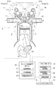
図1に示すように、内燃機関としてのエンジンEの吸気バルブVaの開閉時期を設定する吸気側の弁開閉時期制御機構VTaと、排気バルブVbの開閉時期を設定する排気側の弁開閉時期制御機構VTbと、エンジンEと、を制御するようにECUとして機能するエンジン制御装置40が構成されている。
〔基本構成〕
図1に示すように、内燃機関としてのエンジンEの吸気バルブVaの開閉時期を設定する吸気側の弁開閉時期制御機構VTaと、排気バルブVbの開閉時期を設定する排気側の弁開閉時期制御機構VTbと、エンジンEと、を制御するようにECUとして機能するエンジン制御装置40が構成されている。
図1、図2に示すエンジンE(内燃機関の一例)は、乗用車等の車両に備えられるものを想定している。エンジンEは、クランクシャフト1を支持するシリンダブロック2の上部にシリンダヘッド3を連結し、シリンダブロック2に形成された複数のシリンダボアにピストン4を摺動自在に収容し、ピストン4をコネクティングロッド5によりクランクシャフト1に連結して4サイクル型に構成されている。
エンジンEでは、一方の端部から他方に向けて#1気筒、#2気筒、#3気筒、#4気筒(図2では、#1、#2、#3、#4として示している)が配置され、シリンダの内部空間のうちピストン4とシリンダヘッド3との間に燃焼室が形成される。
シリンダヘッド3には、燃焼室への吸気時に開放する吸気バルブVaと、燃焼室の燃焼ガスの排出時に開放する排気バルブVbとが備えられ、シリンダヘッド3の上部に吸気バルブVaを制御する吸気カムシャフト7と、排気バルブVbを制御する排気カムシャフト8とが備えられる。また、クランクシャフト1の出力スプロケット1Sと、吸気側の弁開閉時期制御機構VTaおよび排気側の弁開閉時期制御機構VTbの駆動ケース21のスプロケット21Sとに亘ってタイミングチェーン6が巻回されている。
更に、シリンダヘッド3には、燃焼室に燃料を噴射するインジェクタ9と点火プラグ10とが備えられている。シリンダヘッド3には、吸気バルブVaを介して燃焼室に空気を供給するインテークマニホールド11と、排気バルブVbを介して燃焼室からの燃焼ガスを送り出すエキゾーストマニホールド12とが連結する。
エンジンEでは、クランクシャフト1を駆動回転するスタータモータ15を備え、クランクシャフト1の近傍位置には回転角と回転速度(単位時間あたりの回転数)とを検知するシャフトセンサ16を備えている。吸気側の弁開閉時期制御機構VTaの近傍には駆動ケース21と内部ロータ22との相対回転位相を検知する吸気側位相センサ17を備え、排気側の弁開閉時期制御機構VTbの近傍には駆動ケース21と内部ロータ22との相対回転位相を検知する排気側位相センサ18を備えている。
尚、エンジンEでは、燃焼対象となる気筒を判別する気筒判別ユニット(図示せず)を備えており、この気筒判別ユニットの一部の構成を用いてシャフトセンサ16が構成されている。
エンジン制御装置40は、エンジンEを制御するECUとして機能するものであり、始動制御部41と、位相制御部42と、燃焼速度推定部43とを備えている。始動制御部41はエンジンEの始動を制御する。位相制御部42は、吸気側の弁開閉時期制御機構VTaと排気側の弁開閉時期制御機構VTbとの相対回転位相を制御する。燃焼速度推定部43は燃焼室での燃焼速度を推定する。エンジン制御装置40の詳細と制御形態は後述する。
〔弁開閉時期制御機構〕
吸気側の弁開閉時期制御機構VTaと、排気側の弁開閉時期制御機構VTbとは共通する構成であるため、これらの上位概念を弁開閉時期制御機構VTと称する。また、弁開閉時期制御機構VTは、電動アクチュエータとしての位相制御モータMの駆動力により対応するバルブの開閉時期を制御する。
吸気側の弁開閉時期制御機構VTaと、排気側の弁開閉時期制御機構VTbとは共通する構成であるため、これらの上位概念を弁開閉時期制御機構VTと称する。また、弁開閉時期制御機構VTは、電動アクチュエータとしての位相制御モータMの駆動力により対応するバルブの開閉時期を制御する。
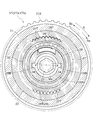
図2~図5には吸気側の弁開閉時期制御機構VTaを示しており、弁開閉時期制御機構VTaは、駆動ケース21と、内部ロータ22とを有すると共に、これらの相対回転位相を位相制御モータMの駆動力により設定する位相調節部を備えている。
駆動ケース21は、外周にスプロケット21Sが形成されると共に、吸気カムシャフト7の回転軸芯Xと同軸芯に配置されている。内部ロータ22は、駆動ケース21に対して相対回転自在に内包され、連結ボルト23により吸気カムシャフト7に連結固定されている。駆動ケース21と内部ロータ22との間に位相調節部が配置され、駆動ケース21の開口部分を覆う位置にフロントプレート24を配置し、これを複数の締結ボルト25により駆動ケース21に締結している。尚、排気側の弁開閉時期制御機構VTbでは、内部ロータ22が排気カムシャフト8に連結する。
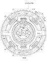
弁開閉時期制御機構VTaでは、図3に示すようにタイミングチェーン6からの駆動力により全体が駆動回転方向Sに回転する。また、位相制御モータMの駆動力により駆動ケース21に対する内部ロータ22の相対回転位相が、駆動回転方向Sと同方向に変位する方向を進角方向Saと称し、この逆方向への変位を遅角方向Sbと称する。
〔弁開閉時期制御機構:位相調節部〕
図2~図5に示すように、位相調節部は、内部ロータ22の内周に一体形成される複数の内歯部26Tを有し、回転軸芯Xと同軸芯に配置されるリングギヤ26を備えると共に、これに咬合するための複数の外歯部27Tを有し、回転軸芯Xに平行する姿勢の偏心軸芯Yと同軸芯に配置されるインナギヤ27を備え、偏心カム体28と、継手部Jとを備えて構成される。
図2~図5に示すように、位相調節部は、内部ロータ22の内周に一体形成される複数の内歯部26Tを有し、回転軸芯Xと同軸芯に配置されるリングギヤ26を備えると共に、これに咬合するための複数の外歯部27Tを有し、回転軸芯Xに平行する姿勢の偏心軸芯Yと同軸芯に配置されるインナギヤ27を備え、偏心カム体28と、継手部Jとを備えて構成される。
この位相調節部では、リングギヤ26の内歯部26Tの歯数に対して、インナギヤ27の外歯部27Tの歯数が1歯だけ少ないものが用いられる。
また、継手部Jは、駆動ケース21に対して内部ロータ22が回転軸芯Xに直交する方向への変位を許しつつ、駆動ケース21と内部ロータ22との相対回転を阻止するオルダム継手として構成されている。
偏心カム体28は、回転軸芯Xと同軸芯で回転するようにフロントプレート24に対して第1軸受31により支持されている。偏心カム体28には、回転軸芯Xに平行する姿勢の偏心軸芯Yを中心とする偏心カム面28Aが一体形成され、偏心カム面28Aに対して第2軸受32を介してインナギヤ27が回転自在に支持される。また、偏心カム面28Aに形成した凹部にバネ体29を嵌め込み、バネ体29の付勢力を、第2軸受32を介してインナギヤ27に作用させている。
偏心カム体28は全体に筒状であり、内周には、一対の係合溝28Bが回転軸芯Xと平行となる姿勢で形成されている。
これにより、リングギヤ26の内歯部26Tの一部にインナギヤ27の外歯部27Tの一部が咬合する。尚、第1軸受31と第2軸受32とはボールベアリングで構成されるものであるが、ブッシュで構成されるものでも良い。
継手部Jは、板材をプレス加工して成る継手部材33を有している。継手部Jは、継手部材33に形成した一対の係合アーム33Aを駆動ケース21の係合溝部21Gに係合させ、継手部材33に形成した一対の係合凹部33Bをインナギヤ27の係合突部27Uに係合させて構成されている。
つまり、継手部材33は、中央部分が環状に形成されると共に、この環状の中央部分から外方に向けて一対の係合アーム33Aを突出形成し、環状の中央部分の空間と連なるように一対の係合凹部33Bを形成した構造を有している。
継手部Jでは、継手部材33が、駆動ケース21の一対の係合溝部21Gを結ぶ直線方向に変位自在となり、継手部材33に対してインナギヤ27が一対の係合突部27Uを結ぶ直線方向に変位自在となる。
位相制御モータM(図2参照)は、エンジンEに支持されると共に、出力軸Maに対して直交姿勢で備えた係合ピン34を備えており、係合ピン34を、偏心カム体28の内周の係合溝28Bに嵌め込んでいる。尚、位相制御モータMには、ブラシレス直流モータが使用されるが、ステッピングモータ等の同期モータを用いても良い。
これにより、エンジンEが停止する状態で作動形態を考えると、位相制御モータMの駆動力で偏心カム体28が回転した場合には、偏心カム面28Aが回転軸芯Xを中心に回転し、この回転に伴いインナギヤ27が回転軸芯Xを中心に公転を開始する。この公転時には、インナギヤ27の外歯部27Tとリングギヤ26の内歯部26Tとの咬合位置がリングギヤ26の内周に沿って変位するためインナギヤ27には偏心軸芯Yを中心に自転させる力が作用する。
つまり、インナギヤ27が1回転だけ公転した場合には、リングギヤ26の内歯部26Tの歯数と、インナギヤ27の外歯部27Tの歯数との差(歯数差)に相当する角度(1歯に対応する角度)だけインナギヤ27に対して回転させようとする回転力(自転力)が作用する。
前述したように、継手部Jは、駆動ケース21に対するインナギヤ27の回転を規制する構造である。そのため、駆動ケース21に対してインナギヤ27が回転することはなく、インナギヤ27に作用する回転力により、駆動ケース21に対してリングギヤ26が回転する。これにより、リングギヤ26と一体的に内部ロータ22が相対回転することになり、駆動ケース21に対する吸気カムシャフト7の回転位相の調節が実現する。
特に、インナギヤ27が、回転軸芯Xを中心に1回転だけ公転した場合には、駆動ケース21に対して吸気カムシャフト7を、インナギヤ27の外歯部27Tの歯数と差(歯数差)に相当する角度だけ回転させるため大きい減速比で調節が実現する。
〔弁開閉時期制御機構:位相調節の概要〕
吸気側の弁開閉時期制御機構VTaによる位相調節を例に挙げると、エンジン制御装置40の位相制御部42は、吸気カムシャフト7の回転速度と等速度で同じ方向に位相制御モータMの出力軸Maを駆動回転することで駆動ケース21と内部ロータ22との相対回転位相が維持する。
吸気側の弁開閉時期制御機構VTaによる位相調節を例に挙げると、エンジン制御装置40の位相制御部42は、吸気カムシャフト7の回転速度と等速度で同じ方向に位相制御モータMの出力軸Maを駆動回転することで駆動ケース21と内部ロータ22との相対回転位相が維持する。
また、吸気カムシャフト7の回転速度を基準にして、位相制御モータMの回転速度を増大する又は低減することにより相対回転位相を進角方向Sa又は遅角方向Sbに変位させる。位相制御モータMの回転速度の増大と低減とに対する相対回転位相の変位方向(進角方向Saと遅角方向Sbとの何れか)は、位相調節部のギヤ構成によって決まる。
特に、弁開閉時期制御機構VTは、位相制御モータMの駆動力により相対回転位相を変位させる。これにより、油圧により変位を実現するものと比較して高速での作動が可能である。また、エンジンEの始動時のように油圧が充分でない状況においても、必要とする回転位相に迅速に設定することが可能である。
〔制御構成〕
図1に示すように、エンジン制御装置40は、シャフトセンサ16と、吸気側位相センサ17と、排気側位相センサ18とからの検知信号が入力すると共に、吸気側と排気側との位相制御モータMと、スタータモータ15とに制御信号を出力し、更に、インジェクタ9と、点火プラグ10とを制御する燃焼管理部19に制御信号を出力する。
図1に示すように、エンジン制御装置40は、シャフトセンサ16と、吸気側位相センサ17と、排気側位相センサ18とからの検知信号が入力すると共に、吸気側と排気側との位相制御モータMと、スタータモータ15とに制御信号を出力し、更に、インジェクタ9と、点火プラグ10とを制御する燃焼管理部19に制御信号を出力する。
始動制御部41は、スタータモータ15を制御することによりクランキングを実現する。位相制御部42は、吸気側の弁開閉時期制御機構VTaの位相制御モータMと、排気側の弁開閉時期制御機構VTbの位相制御モータMとを制御することにより、吸気バルブVaの開閉時期の設定と、排気バルブVbの開閉時期の設定とを可能にする。燃焼速度推定部43は、燃焼室で燃焼速度を推定する。
以下の制御では、図7、図8に示すように、吸気バルブVaの開時期であるIVO、排気バルブVbの開時期であるEVOを早める方向を進角方向(進角側)と称し、この逆の方向を遅角方向(遅角側)として説明している。
また、燃焼速度推定部43が燃焼速度を推定する際には、点火プラグ10による点火タイミングを基準として、シャフトセンサ16で検知されるクランクシャフト1の回転速度の増加傾向に基づいて燃焼速度を推定する手法が採用されている。尚、この燃焼速度推定部43は燃焼速度を計測するための専用のセンサを備えるものが考えられ、燃焼速度を推定する際に予め設定されたテーブルデータを参照することや、複数のタイミングで取得したシャフトセンサ16の検知信号に基づく処理を行うものが考えられる。
エンジン制御装置40において、始動制御部41、位相制御部42、及び、燃焼速度推定部43はソフトウエアで構成されるものを想定しているが、これらが、ロジック等を有する回路で成るハードウエアで構成されるものでも良く、ソフトウエアとハードウエアとの組み合わせによって構成されるものでも良い。
また、燃焼管理部19は、インジェクタ9に対して燃料を供給するポンプ類の作動を管理すると共に、点火プラグ10に電力を供給するイグニッション回路の制御により点火順序や点火タイミングを管理する。
〔制御形態〕
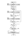
このような構成から図6のフローチャートと、図7のタイミングダイヤグラムと、図8のタイミングチャートとに示すように、エンジンEを始動する制御信号を取得した場合には、吸気側の弁開閉時期制御機構VTaの開閉時期を所定の値に設定すると共に、スタータモータ15の駆動によりクランキングを開始し、気筒判別を行う(#101~#103ステップ)。
このような構成から図6のフローチャートと、図7のタイミングダイヤグラムと、図8のタイミングチャートとに示すように、エンジンEを始動する制御信号を取得した場合には、吸気側の弁開閉時期制御機構VTaの開閉時期を所定の値に設定すると共に、スタータモータ15の駆動によりクランキングを開始し、気筒判別を行う(#101~#103ステップ)。
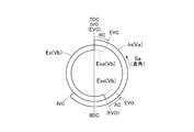
#101ステップでは、図7に示すように吸気バルブVaの開時期であるIVOがピストン4の上死点TDCと一致するように吸気バルブVaの開閉時期が設定される。図7のタイミングダイヤグラムでは、排気バルブVbにおいて排気が行われる領域を排気領域Exとして示し、吸気バルブVaにおいて吸気が行われる領域を吸気領域Inとして示している。
次に、図7、図8に示すように、各気筒において排気バルブVbが開作動する以前に排気側の弁開閉時期制御機構VTbの制御により、開時期であるEVOを進角作動量ACだけ進角制御し、設定タイミングが経過した後に閉時期であるEVCを遅角作動量RCだけ遅角制御する(#104~#106ステップ)。
この制御では、設定タイミングとして、排気バルブVbが全開に達したタイミングが決められている。この制御では、各気筒毎に排気バルブVbの開時期であるEVOを進角制御により進角作動量ACに対応した時間だけ早めると共に、排気バルブVbの閉時期であるEVCを遅角制御により遅角作動量RCに対応した時間だけ遅らせる。これにより、排気バルブVbが開放状態にある時間を延長する制御が実行される。
図8のタイミングチャートでは、クランクアングルを横軸にとり、吸気バルブVaと排気バルブVbとのリフト量を縦軸にとっている。また、排気バルブVbの開時期であるEVOと閉時期であるEVCとが所定時期に固定された状態の排気バルブVbの開閉特性を破線により排気基本曲線Exとして示しており、#104~#105ステップの制御により、排気バルブVbの開放時間を延長した特性の排気延長曲線Exeとして示している。
つまり、排気基本曲線Exにおける開時期である(EVO)と比較して、排気延長曲線Exeの開時期であるEVOが早い時期となり、排気基本曲線Exにおける閉時期である(EVC)と比較して排気延長曲線Exeの閉時期であるEVCが遅い時期となる。
これにより、排気バルブVbの開時期であるEVOが進角側に変位することで1つの膨張行程における燃焼室の空気の排出を早期に行い、この膨張行程におけるポンプロスを低下させる。また、同じ膨張行程において排気バルブVbの閉時期であるEVCが遅角側に変位することで膨張行程から吸気行程に移行する際に、吸気バルブVaとの間でのオーバーラップを大きくして吸気行程におけるポンプロスを低減する。その結果、クランクシャフト1に作用する負荷を軽減してクランクシャフト1の回転速度の高速化を可能にする。
次に、クランクシャフト1の回転速度が燃焼可能な速度に達したことを判定した後に、燃焼を開始し、各気筒での燃焼が行われた後に、スタータモータ15を停止する。そして、燃焼速度推定部43が推定した燃焼速度に対応して排気側の弁開閉時期制御機構VTbを制御し、排気バルブVbの閉時期であるEVCを設定する(#107~#110ステップ)。
この制御のうち、#108ステップでは、燃焼管理部19が、所定の気筒で最初の燃焼を行い、これに続いて設定された順序で各燃焼室の燃焼が行われる。この制御では、図8に示すように、排気延長曲線Exeの閉時期であるEVCが、吸気曲線Inの開時期であるIVOより後に設定されるため、排気バルブVbが開放する状態において、吸気バルブVaが開放するオーバーラップ状態となる。
このように排気バルブVbの開状態と吸気バルブVaの開状態とがオーバーラップするため、各燃焼室での燃焼が行われる状況では、吸気バルブVaでの吸気行程において燃焼ガスが燃焼室に吸引される内部EGRの状態となる。この内部EGR状態では、1行程前の燃焼ガスを燃焼室に取り込むため、燃焼室の温度上昇を迅速に行える。
この反面、1行程前の燃焼ガスが燃焼室に取り込まれるため燃焼速度が低下し、燃焼の不安定化を招くこともある。このため、例えば、設定時間が経過した後に排気バルブVbの開閉特性を排気基本曲線Exに戻す制御や、必要がある場合に開閉時期を進角方向に変位させて早めることで燃焼を安定させる。
つまり、排気側の弁開閉時期制御機構VTbが位相制御モータMにより高速で位相制御が可能に構成されるため、1つの膨張行程において排気バルブVbの開時期であるEVOを進角作動量ACにより進角方向に変位させると共に、排気バルブVbの閉時期であるEVCを遅角作動量RCにより遅角方向に変位させる制御が実現する。
また、この制御では排気バルブVbの開時期であるEVOが最進角位相に達し、閉時期であるEVCが最遅角位相に達することが理想である。しかし、排気側の弁開閉時期制御機構VTbの高速作動にも限度があるため、排気基本曲線Exと比較して開時期であるEVOが進角方向に変位し、閉時期であるEVCが遅角方向に変位する程度の制御でクランキング時の付加を軽減する効果を得る。
特に、排気側の弁開閉時期制御機構VTbによって排気バルブVbの開閉時期を変更した場合でも、吸気行程における吸気量を変化させることがないため、排気側の弁開閉時期制御機構VTbの開閉タイミングを任意に設定しても空燃比に影響を与えることのない燃焼が可能になる。
〔別実施形態〕
本発明は、上記した実施形態以外に以下のように構成しても良い(実施形態と同じ機能を有するものには、実施形態と共通の番号、符号を付している)。
本発明は、上記した実施形態以外に以下のように構成しても良い(実施形態と同じ機能を有するものには、実施形態と共通の番号、符号を付している)。
(a)実施形態で説明した図6のフローチャートの#101ステップで設定する吸気バルブVaの開閉時期を、図9に示すように、遅角方向に変位させて遅らせる(後述する吸気遅角曲線Inr)。
別実施形態(a)の制御でも、各気筒毎に排気バルブVbの開時期であるEVOを進角制御により進角作動量ACだけ進角制御すると共に、排気バルブVbの閉時期であるEVCを遅角制御により遅角作動量RCだけ遅角制御することで排気バルブVbが開放状態にある時間を延長する制御が実行される。これにより、図9に示す如く、排気基本曲線Exにおける開時期である(EVO)と比較して、開時期であるEVOが早く、閉時期であるEVCが遅れた排気延長曲線Exeに従って排気バルブVbが開閉する。
更に、開時期であるIVOと閉時期であるIVCとが所定時期に固定された状態の吸気バルブVaの開閉特性を吸気曲線Inとした場合に、この吸気曲線Inより、開時期であるIVOと閉時期であるIVCとが遅角側に遅角作動量RCだけ変位するように吸気バルブVaの開閉時期が設定される。このように遅角側に変位した特性曲線を吸気遅角曲線Inrとして示している。
この制御形態では、排気バルブVbの閉時期であるEVCと、吸気バルブVaの開時期であるIVOとの間にネガティブオーバーラップNOLを形成しており、クランキング時には(特にクランキングの初期には)クランクシャフト1に作用する負荷を軽減する。更に、排気バルブVbでのポンプロスの低下を図ることにより、クランクシャフト1に作用する負荷を一層軽減してクランクシャフト1の回転の高速化を実現する。
(b)別実施形態(a)で説明したように、吸気側の弁開閉時期制御機構VTaの制御と、排気側の弁開閉時期制御機構VTbの制御とによりネガティブオーバーラップNOLが形成される状況では、図10に示す制御も考えられる。図10では、ネガティブオーバーラップNOLに起因する負荷を軽減するように、排気バルブVbの閉時期であるEVCを図9に示す閉時期(EVC)より更に遅角させる(遅らせる)制御が行われている。
別実施形態(b)の制御では、吸気側の弁開閉時期制御機構VTaが油圧式で、最遅角ロック機構を備えた構成を想定すると理解が容易である。また、別実施形態(b)の制御でも、別実施形態(a)と同様に、各気筒毎に排気バルブVbの開時期であるEVOを進角制御により進角作動量AC(図9を参照)だけ進角制御すると共に、排気バルブVbの閉時期であるEVCを遅角制御により遅角作動量RC(図9を参照)だけ遅角制御することで排気バルブVbの開放時間を延長する制御が実行される。
更に、この制御のように開時期であるEVOが早く、閉時期であるEVCが遅れた排気延長曲線Exeに従って排気バルブVbが開閉する制御形態に加えて、排気延長曲線Exeの全体を遅角方向に変位させることにより、排気変位曲線Exerに従って排気バルブVbの開閉が行われるように構成される。
このような制御を行うことにより、ネガティブオーバーラップNOLを解消し、ネガティブオーバーラップNOLに起因するポンピングロスの低減が可能となる。
(c)別実施形態(b)でも説明したように、吸気側の弁開閉時期制御機構VTaを油圧によって開閉時期を設定できるように構成する。
本発明は、内燃機関の制御装置に利用することができる。
1 クランクシャフト
4 ピストン
15 スタータモータ
E エンジン(内燃機関)
M 位相制御モータ(電動アクチュエータ)
Va 吸気バルブ
Vb 排気バルブ
VT 弁開閉時期制御機構
4 ピストン
15 スタータモータ
E エンジン(内燃機関)
M 位相制御モータ(電動アクチュエータ)
Va 吸気バルブ
Vb 排気バルブ
VT 弁開閉時期制御機構
Claims (2)
- クランクシャフトの回転に連係してシリンダ内で往復作動するピストンと前記クランクシャフトの回転に連係して燃焼室を開閉する吸気バルブおよび排気バルブとを有する複数の気筒と、前記クランクシャフトを駆動回転するスタータモータと、電動アクチュエータの駆動により前記排気バルブの開閉時期を設定する弁開閉時期制御機構と、を備えて内燃機関が構成され、
前記スタータモータによってクランキングが行われる際には、複数の前記気筒のうち排気行程にあるものについて前記排気バルブの開時期であるEVOを進角させると共にこの排気バルブの閉時期であるEVCを遅角させるように前記電動アクチュエータを制御する内燃機関の制御装置。 - 複数の前記気筒のうち最後に燃焼するように順序が設定された前記気筒の最初の燃焼が行われた後に、前記燃焼室での燃焼速度に基づいて前記電動アクチュエータを制御する請求項1に記載の内燃機関の制御装置。
Applications Claiming Priority (2)
| Application Number | Priority Date | Filing Date | Title |
|---|---|---|---|
| JP2017102038A JP2018197521A (ja) | 2017-05-23 | 2017-05-23 | 内燃機関の制御装置 |
| JP2017-102038 | 2017-05-23 |
Publications (1)
| Publication Number | Publication Date |
|---|---|
| WO2018216293A1 true WO2018216293A1 (ja) | 2018-11-29 |
Family
ID=64396470
Family Applications (1)
| Application Number | Title | Priority Date | Filing Date |
|---|---|---|---|
| PCT/JP2018/007441 Ceased WO2018216293A1 (ja) | 2017-05-23 | 2018-02-28 | 内燃機関の制御装置 |
Country Status (2)
| Country | Link |
|---|---|
| JP (1) | JP2018197521A (ja) |
| WO (1) | WO2018216293A1 (ja) |
Families Citing this family (2)
| Publication number | Priority date | Publication date | Assignee | Title |
|---|---|---|---|---|
| DE102019103104B3 (de) * | 2019-02-08 | 2020-06-04 | Schaeffler Technologies AG & Co. KG | Nockenwellenverstellsystem und Verfahren zum Betrieb eines Nockenwellenverstellsystems |
| US11480123B1 (en) * | 2021-05-12 | 2022-10-25 | Ford Global Technologies, Llc | Methods and system for starting an engine |
Citations (3)
| Publication number | Priority date | Publication date | Assignee | Title |
|---|---|---|---|---|
| JPS63253132A (ja) * | 1987-04-08 | 1988-10-20 | Mazda Motor Corp | エンジンの制御装置 |
| WO2014068670A1 (ja) * | 2012-10-30 | 2014-05-08 | トヨタ自動車 株式会社 | 内燃機関の制御装置 |
| WO2016031557A1 (ja) * | 2014-08-25 | 2016-03-03 | アイシン精機株式会社 | 弁開閉時期制御装置 |
-
2017
- 2017-05-23 JP JP2017102038A patent/JP2018197521A/ja active Pending
-
2018
- 2018-02-28 WO PCT/JP2018/007441 patent/WO2018216293A1/ja not_active Ceased
Patent Citations (3)
| Publication number | Priority date | Publication date | Assignee | Title |
|---|---|---|---|---|
| JPS63253132A (ja) * | 1987-04-08 | 1988-10-20 | Mazda Motor Corp | エンジンの制御装置 |
| WO2014068670A1 (ja) * | 2012-10-30 | 2014-05-08 | トヨタ自動車 株式会社 | 内燃機関の制御装置 |
| WO2016031557A1 (ja) * | 2014-08-25 | 2016-03-03 | アイシン精機株式会社 | 弁開閉時期制御装置 |
Also Published As
| Publication number | Publication date |
|---|---|
| JP2018197521A (ja) | 2018-12-13 |
Similar Documents
| Publication | Publication Date | Title |
|---|---|---|
| CN101813014B (zh) | 具有可变气门装置的内燃机 | |
| US8843294B2 (en) | Apparatus for and method of controlling variable valve timing mechanism | |
| WO2018216291A1 (ja) | 内燃機関の制御装置 | |
| WO2018216292A1 (ja) | 内燃機関の制御装置 | |
| JP5088508B2 (ja) | 可変動弁装置付エンジン | |
| JP6384389B2 (ja) | 内燃機関の制御ユニット | |
| JP2018197521A (ja) | 内燃機関の制御装置 | |
| JP6384390B2 (ja) | 内燃機関の制御ユニット | |
| WO2016098768A1 (ja) | 内燃機関の可変動弁システム及び可変動弁制御装置 | |
| JP2010127249A (ja) | 内燃機関 | |
| JP7397990B2 (ja) | 内燃機関の停止制御装置 | |
| KR101648620B1 (ko) | 내연 기관의 가변 밸브 작동 장치 | |
| WO2018216290A1 (ja) | 内燃機関の制御装置 | |
| JP7559615B2 (ja) | 内燃機関の制御装置 | |
| JP2021021346A (ja) | 内燃機関の可変圧縮比システム | |
| JP7509019B2 (ja) | 弁開閉時期制御装置 | |
| JP2017180122A (ja) | 内燃機関の制御装置 | |
| JP5131483B2 (ja) | 可変動弁装置付エンジン | |
| JP5516896B2 (ja) | 可変動弁装置付内燃機関 | |
| JP2019007447A (ja) | 内燃機関 | |
| JP2017218915A (ja) | ディーゼルエンジンの制御装置 | |
| JPH05156972A (ja) | 内燃機関のバルブタイミング制御装置 | |
| JP2010270691A (ja) | 内燃機関の始動制御装置 |
Legal Events
| Date | Code | Title | Description |
|---|---|---|---|
| 121 | Ep: the epo has been informed by wipo that ep was designated in this application |
Ref document number: 18806047 Country of ref document: EP Kind code of ref document: A1 |
|
| NENP | Non-entry into the national phase |
Ref country code: DE |
|
| 122 | Ep: pct application non-entry in european phase |
Ref document number: 18806047 Country of ref document: EP Kind code of ref document: A1 |