WO2018216282A1 - 回転電機 - Google Patents
回転電機 Download PDFInfo
- Publication number
- WO2018216282A1 WO2018216282A1 PCT/JP2018/006678 JP2018006678W WO2018216282A1 WO 2018216282 A1 WO2018216282 A1 WO 2018216282A1 JP 2018006678 W JP2018006678 W JP 2018006678W WO 2018216282 A1 WO2018216282 A1 WO 2018216282A1
- Authority
- WO
- WIPO (PCT)
- Prior art keywords
- winding
- phase
- core
- crossover
- portions
- Prior art date
- Legal status (The legal status is an assumption and is not a legal conclusion. Google has not performed a legal analysis and makes no representation as to the accuracy of the status listed.)
- Ceased
Links
Images





Classifications
-
- H—ELECTRICITY
- H02—GENERATION; CONVERSION OR DISTRIBUTION OF ELECTRIC POWER
- H02K—DYNAMO-ELECTRIC MACHINES
- H02K3/00—Details of windings
- H02K3/04—Windings characterised by the conductor shape, form or construction, e.g. with bar conductors
- H02K3/28—Layout of windings or of connections between windings
-
- H—ELECTRICITY
- H02—GENERATION; CONVERSION OR DISTRIBUTION OF ELECTRIC POWER
- H02K—DYNAMO-ELECTRIC MACHINES
- H02K3/00—Details of windings
- H02K3/46—Fastening of windings on the stator or rotor structure
- H02K3/52—Fastening salient pole windings or connections thereto
- H02K3/521—Fastening salient pole windings or connections thereto applicable to stators only
- H02K3/522—Fastening salient pole windings or connections thereto applicable to stators only for generally annular cores with salient poles
-
- H—ELECTRICITY
- H02—GENERATION; CONVERSION OR DISTRIBUTION OF ELECTRIC POWER
- H02K—DYNAMO-ELECTRIC MACHINES
- H02K1/00—Details of the magnetic circuit
- H02K1/06—Details of the magnetic circuit characterised by the shape, form or construction
- H02K1/12—Stationary parts of the magnetic circuit
- H02K1/14—Stator cores with salient poles
- H02K1/146—Stator cores with salient poles consisting of a generally annular yoke with salient poles
-
- H—ELECTRICITY
- H02—GENERATION; CONVERSION OR DISTRIBUTION OF ELECTRIC POWER
- H02K—DYNAMO-ELECTRIC MACHINES
- H02K2203/00—Specific aspects not provided for in the other groups of this subclass relating to the windings
- H02K2203/06—Machines characterised by the wiring leads, i.e. conducting wires for connecting the winding terminations
Definitions
- the present invention relates to a rotating electrical machine, and more particularly, to a rotating electrical machine including a winding including a winding portion wound around a plurality of core portions and a crossover portion connecting the winding portions.
- a rotating electrical machine having a winding including a winding portion wound around a plurality of core portions and a crossover portion connecting the winding portions is known.
- Such a rotating electrical machine is disclosed in, for example, Japanese Patent Application Laid-Open No. 2015-92806.
- Japanese Patent Laying-Open No. 2015-92806 discloses a rotating electric machine that includes a plurality (12 pieces) of core components divided in the circumferential direction constituting an armature core and an insulator provided so as to cover the core components.
- the insulator includes an insulating part that covers each divided core component and a connecting part that connects the pair of insulating parts.
- four core components are provided for each phase (U phase, V phase, and W phase). Then, two of the four core components are arranged on one side with respect to the rotation center as viewed from the rotation axis direction, and the remaining two are arranged on the other side with respect to the rotation center.
- the two core constituent parts arranged on one side are arranged so as to be adjacent to each other.
- the insulating part which covers the two core constituent parts arranged on one side with respect to the rotation center and the insulating part which covers the two core constituent parts arranged on the other side with respect to the rotational center are connected. Connected by each other.
- the connecting portion has a thin plate shape (band shape), and a hole portion through which the rotating shaft of the rotating electrical machine passes is provided in the center portion.
- this rotating electric machine has a winding.
- the winding includes a winding part that is wound around each divided core component via an insulating part, and a crossover part that connects the winding parts.
- a winding part wound around two core constituent parts arranged on one side with respect to the rotation center and two core constituent parts arranged on the other side with respect to the rotation center The winding part wound is connected by the crossover part.
- the crossover part is arrange
- each of the U-phase, V-phase, and W-phase, the four core components, the insulator and the winding group (armature component unit) are combined along the rotation axis direction.
- the core component part of each phase is arrange
- the U-phase, V-phase, and W-phase coupling portions are stacked along the rotational axis direction on the inner diameter side of the annular armature core (and the upper side of the armature core). It is arranged with.
- the connecting wire part of each phase is laminated
- the connecting part of a thin plate shape is arrange
- a connecting portion that suppresses interference between the crossover portions is disposed on the inner diameter side of the annular armature core (and on the upper side of the armature core). ing. That is, when viewed from the rotation axis direction, the connecting portion is disposed so as to straddle the inner diameter side portion (portion where the rotor is disposed) of the annular armature core. For this reason, since it is necessary to avoid interference between the rotor arranged on the inner diameter side of the armature core, the bearing of the rotary shaft, and the connecting portion, there is a problem that the design of the rotary electric machine is restricted.
- the present invention has been made to solve the above-described problems, and one object of the present invention is to suppress the occurrence of restrictions on the design while suppressing the interference between the crossover portions. It is to provide a possible rotating electrical machine.
- a rotating electrical machine includes an armature core having a plurality of core portions divided in the circumferential direction, and a winding portion wound around the plurality of core portions; And a plurality of windings are provided so as to correspond to a plurality of phases, and the plurality of windings is a rotation of the armature core.
- a first winding disposed on one side in the axial direction and a second winding having a crossover portion disposed on the other side in the rotational axis direction of the armature core are included.
- the crossover portions of each of the plurality of phases are dispersed on one side and the other side in the rotational axis direction of the armature core. Therefore, unlike the case where the connecting wire portions of the plurality of phases are arranged only on one side (or only the other side) in the rotation axis direction of the armature core, the connecting wire portions are less likely to interfere with each other.
- JP-A-2015-92806 it is possible to suppress the interference between the crossover parts without providing a connecting part between the crossover parts in order to suppress the interference between the crossover parts. Therefore, there is no restriction on the design of the rotating electrical machine due to the arrangement of the connecting portion. As a result, it is possible to suppress the restriction in the design of the rotating electrical machine while suppressing the interference between the crossover portions.
- the length of one of the connecting wire portions is increased so that the connecting wire portions do not interfere with each other, and the other connecting wire portion is bypassed. There is no need to do.
- an increase in the length of the winding is suppressed, so that it is possible to suppress an increase in the resistance value of the winding and to increase the length of the winding (jump out in the direction of the rotation axis). This can suppress an increase in the length of the rotating electrical machine in the direction of the rotation axis.
- the armature core is moved along the rotation axis direction so that the plurality of core portions of each phase wound with the windings are close to each other. Even when assembled, the crossovers of each phase do not interfere. Thereby, assembly of a rotary electric machine (armature core) can be performed easily.
- three windings are provided so as to correspond to three phases, and the three windings include a first winding of a first phase and a second winding of the second phase.
- a second winding and a first winding of a third phase are included.
- the connecting wire portion of the three windings corresponding to the three phases is distributed on one side and the other side in the rotation axis direction of the armature core. It is possible to suppress the restriction in the design of the rotating electrical machine while suppressing the interference between the line portions.
- the first winding of the first phase and the first winding of the third phase are one side in the circumferential direction of the core portion on one end side in the circumferential direction of the plurality of core portions.
- the second phase second winding starts winding from one circumferential side of the core portion on the other end side in the circumferential direction among the plurality of core portions, and is connected to the other side in the rotational axis direction. Winding ends on the other side in the circumferential direction of the core portion on the one end side in the circumferential direction among the plurality of core portions via the portion.
- the 1st winding and the 2nd winding Both can be formed. As a result, it is possible to suppress interference between the crossover portions while suppressing the complexity of the rotating electrical machine manufacturing apparatus.
- the winding start portion of the first winding of the first phase and the first winding of the third phase A winding end portion is arranged so as to extend from between the adjacent core portions to one side in the rotation axis direction, and the winding start portion of the second winding of the second phase and the first phase of the first phase A winding end portion of the winding is disposed so as to extend from between the adjacent core portions to one side in the rotation axis direction, and the winding start portion of the first winding of the third phase and the second phase
- the winding end portion of the second winding is disposed so as to extend from between the adjacent core portions to one side in the rotational axis direction.
- the winding start part and winding end part are arrange
- ECU engine control unit
- the crossover portion of the second winding of the second phase is preferably arranged on the lead wire side, and the first phase The crossover portion between the first winding and the first winding of the third phase is disposed on the side opposite to the lead wire side.
- the connecting wire portions of the first winding and the second winding are arranged outside the surface on the inner diameter side of the armature core when viewed from the rotation axis direction. ing.
- crossover part is arrange
- a crossover part and an electric machine Interference with a rotor, a rotating shaft, a bearing, and the like arranged on the inner side of the inner diameter side surface of the child core can be suppressed. Thereby, it can suppress effectively that restrictions arise in the design of a rotary electric machine.
- the configuration of the motor 100 (an example of a rotating electrical machine) according to the present embodiment will be described with reference to FIGS.
- the motor 100 is configured as a brushless motor and includes an armature core 10.
- the armature core 10 has a plurality of core portions 11 divided in the circumferential direction. Specifically, the armature core 10 includes nine core portions 11.
- the “circumferential direction” means the circumferential direction of the annular armature core 10.
- an insulator 12 is provided so as to cover the core portion 11.
- the insulator 12 is made of resin or the like and has a function of insulating a winding 20 and a core portion 11 described later.
- the notch 12b is each provided in the edge part 12a of the one side of the rotating shaft direction of the insulator 12, and the edge part 12a of the other side.
- the “rotation axis direction” means a direction (Z direction) along the rotation axis of a rotor (not shown).
- the motor 100 includes a winding 20.
- the winding 20 includes a winding portion 21 wound around the plurality of core portions 11 and a crossover portion 22 that connects the winding portions 21 to each other.
- the winding portion 21 is wound around the core portion 11 a plurality of times via the insulator 12.
- the crossover part 22 is a part (one conducting wire) of the coil
- a plurality of windings 20 are provided so as to correspond to a plurality of phases.
- Three windings 20 are provided so as to correspond to three phases.
- the three windings 20 include a U-phase (an example of the first phase) winding 20U (an example of the first winding) and a V-phase (an example of the second phase) 20V (second example).
- An example of a winding) and a winding 20W (an example of a first winding) of a W phase an example of a third phase).
- the winding 20U includes three winding portions 21 (U1, U2, U3) and two crossover portions 22U that connect the winding portions 21 to each other.
- the winding 20V includes three winding portions 21V (V1, V2, V3) and two crossover portions 22V that connect the winding portions 21 to each other.
- the winding 20W includes three winding portions 21 (W1, W2, W3) and two crossover portions 22W that connect the winding portions 21 to each other.
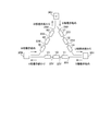
- the winding 20U, the winding 20V, and the winding 20W are ⁇ -connected. Specifically, the winding start portion of winding 20U and the winding end portion of winding 20W are connected to terminal 30U.
- winding start portion of the winding 20V and the winding end portion of the winding 20U are connected to the terminal 30V. Further, the winding start portion of the winding 20W and the winding end portion of the winding 20V are connected to the terminal 30W. In addition, the winding direction of the winding part 21 is counterclockwise (see FIG. 8).
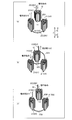
- the crossover portion 22U of the winding 20U (see FIG. 2A) and the crossover portion 22W of the winding 20W (see FIG. 2A). 2C) is arranged on one side (Z1 direction side) of the armature core 10 in the rotation axis direction.
- the crossover portion 22V (see FIG. 2B) of the winding 20V is disposed on the other side (Z2 direction side) of the armature core 10 in the rotation axis direction.
- the crossover portion 22V of the V-phase winding 20V is disposed on the lead wire side.
- the lead wire side is the side (Z2 direction side) where the winding start portion and winding end portion of the winding 20 of each phase are arranged. Further, the connecting wire portion 22U of the U-phase winding 20U and the connecting wire portion 22W of the W-phase winding 20W are arranged on the opposite side (Z1 direction side) to the lead wire side.
- winding 20U is outside the surface 10a by the side of the internal diameter of the armature core 10 (core part 11) seeing from a rotating shaft direction.
- the crossover portion 22U is indicated by a thick solid line
- the crossover portion 22W is indicated by a thick dotted line.
- FIG. 4 shows a cross section of the winding 20.
- the crossover portion 22U is arranged on one side (Z1 direction side) of the winding portion 21 in the rotation axis direction. Moreover, the crossover part 22U is arrange
- the connecting wire portion 22U of the winding 20U and the connecting wire portion 22W of the winding 20W are on one side (Z1) of the winding portion 21 in the rotation axis direction. (Direction side) is arranged so as to partially intersect.
- the crossover portion 22 is configured to be disposed between the inner diameter side surface 10a of the core portion 11 and the inner diameter side surface 12c of the insulator 12 (between the width W) when viewed from the rotational axis direction. Has been.
- the crossover portion 22V of the winding 20V is disposed outside the surface 10a on the inner diameter side of the armature core 10 (core portion 11) when viewed from the rotation axis direction. Specifically, the crossover portion 22V is disposed on one side (Z2 direction side) of the winding portion 21 in the rotation axis direction. Moreover, the crossover part 22V is arrange
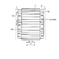
- the connecting wire portion 22 extends from one end portion 12a (the other end portion 12a) in the rotational axis direction of the insulator 12 to a predetermined distance L. It is comprised so that it may be arrange
- winding 20U is one side of the circumferential direction of the core part 11 of the one end side (R1 direction side) of the circumferential direction among the three core parts 11.
- FIG. Winding is started from the side (R1 direction side), and the other end side in the circumferential direction of the three core portions 11 (via the connecting wire portion 22U disposed on one side (Z1 direction side) in the rotation axis direction ( The winding ends on the other side (R2 direction side) in the circumferential direction of the core portion 11 on the R2 direction side.
- the winding 20U starts to be wound from the R1 direction side of the core portion 11 disposed on the R1 direction side, and after the winding portion 21 (U1) is formed, via the crossover portion 22U, It is wound around the central core portion 11 to form a winding portion 21 (U2). Thereafter, the winding 20U is wound around the core portion 11 on the R2 direction side via the crossover portion 22U to form the winding portion 21 (U3), and then finishes winding on the R2 direction side of the core portion 11 . Further, as shown in FIG. 7C, the configuration of the winding 20W is the same as the configuration of the winding 20U.
- the winding 20V is one side (R1 direction side) in the circumferential direction of the core portion 11 on the other end side (R2 direction side) of the three core portions 11 in the circumferential direction. ) And at one end side in the circumferential direction (R1 direction side) of the three core portions 11 via the connecting wire portion 22V arranged on the other side (Z2 direction side) in the rotation axis direction. The winding ends on the other side (R2 direction side) of the core portion 11 in the circumferential direction.
- the winding 20V is started from the R1 direction side of the core portion 11 disposed on the R2 direction side to form the winding portion 21 (V1), and then, via the crossover portion 22V, Winding portion 21 (V2) is formed by being wound around the central core portion 11. Thereafter, the winding 20V is wound around the core portion 11 disposed on the R1 direction side via the crossover portion 22V to form the winding portion 21 (V3), and then the R2 direction side of the core portion 11 is formed. Ends in winding.
- each winding start portion of the winding 20 is disposed so as to extend in the Z2 direction from the inner side of the winding portion 21 (side closer to the core portion 11).
- each winding end portion of the winding 20 is disposed so as to extend in the Z2 direction from the outside of the winding portion 21 (the side far from the core portion 11).
- the winding start portion (winding end portion) refers to the end portion of the winding 20 and the portion in the vicinity of the end portion (the portion from the end portion to the winding portion 21 wound around the core portion 11). Including.
- a U-phase winding 20U, a V-phase winding 20V, and a W-phase winding 20W are arranged in this order in the circumferential direction.
- the winding part 21 is arrange
- the winding start portion of the U-phase winding 20W and the winding end portion of the W-phase winding 20W are disposed between the adjacent core portions 11 (slot 13a) in the rotation axis direction. It arrange
- winding start portion of the W-phase winding 20W and the winding end portion of the V-phase winding 20V extend from between the adjacent core portions 11 (slot 13c) to the other side in the rotation axis direction. Is arranged. Note that the winding start portion and the winding end portion of the winding 20 are arranged at positions corresponding to the notches 12b of the insulator 12 when viewed from the inner diameter side.
- the winding start portion and the winding end portion of each phase are bent radially inward and then bent to extend in the Z2 direction. Further, the winding end portion of the U-phase winding 20U, the winding start portion and winding end portion of the V-phase winding 20V, and the winding start portion of the W-phase winding 20W are V-phase transitions. It is bent so as to dodge the line portion 22V.
- FIG. 9 [Assembly method of armature core] As shown in FIG. 9, three core portions 11 (hereinafter referred to as core units 40V) around which a V-phase winding 20V is wound are arranged in an annular shape (arc shape). Further, three core portions 11 (hereinafter referred to as core units 40U) around which the U-phase winding 20U is wound are arranged in an annular shape (arc shape). Also, the three core portions 11 around which the W-phase winding 20W is wound are arranged in an annular shape (arc shape).
- the core unit 40V, the core unit 40U, and the core unit 40W are moved so as to approach each other along the rotation axis direction (Z direction) in a state where the core unit 40V, the core unit 40W, and the core unit 40W are rotated relative to each other by approximately 120 degrees.
- the core unit 40U and the core unit 40W are assembled so that the W-phase connecting wire portion 22W avoids the U-phase connecting wire portion 22U.
- the V-phase connecting wire portion 22V is disposed on the opposite side (lead wire side) to the U-phase connecting wire portion 22U and the W-phase connecting wire portion 22W, and thus does not interfere.
- the V-phase connecting wire portion 22V, the U-phase connecting wire portion 22U, and the W-phase connecting wire portion 22W are respectively on the other side (Z2 direction side) and one side (Z1 direction side) in the rotation axis direction. Therefore, it is possible to suppress the interference between the crossover portions 22. As a result, the armature core 10 can be easily assembled by moving the core unit 40V, the core unit 40U, and the core unit 40W along the rotation axis direction.
- each of the three-phase connecting wire portions 22 is disposed only on one side (or only on the other side) of the armature core 10 while rotating the U-phase connecting wire portion 22U, While it is possible to arrange the W-phase connecting wire portion 22W, when arranging the V-phase connecting wire portion 22V, the V-phase connecting wire portion 22V becomes the U-phase connecting wire portion 22U and / or Interference with the W-phase crossover 22W.
- the connecting wire portions 22 of each of the plurality of phases are dispersed on one side and the other side in the rotation axis direction of the armature core 10, so that the connecting wire portions 22 of the plurality of phases are armature cores.
- the crossover line portions 22 are less likely to interfere with each other.
- the connection of the crossover part 22 is suppressed without providing a connecting part between the crossover parts 22. Therefore, the design restriction of the motor 100 due to the arrangement of the connecting portion does not occur. As a result, it is possible to suppress the restriction on the design of the motor 100 while suppressing the interference between the crossover portions 22.
- the crossover portions 22 of the three windings 20 corresponding to the three phases are distributed on one side and the other side in the rotation axis direction of the armature core 10, the three-phase motor 100. Therefore, it is possible to suppress the restriction on the design of the motor 100 while suppressing the interference between the crossover portions 22.
- the winding direction of the winding 20U and the winding 20W and the winding 20V are the same (counterclockwise), so the winding 20U, the winding 20V and All of the windings 20W can be formed. As a result, it is possible to suppress interference between the connecting wire portions 22 while suppressing the manufacturing apparatus of the motor 100 from becoming complicated.
- the winding start portion and the winding end portion of the winding 20 are arranged so as to be close to each other, so that the winding start portion and the winding end portion of the winding 20 are connected to the terminal 30U,
- winding start portion and the winding end portion of the winding 20 are aggregated so as to be close to each other, the winding start portion and the winding end portion of the winding 20 are connected to other equipment (ECU (engine control). Unit) etc.).
- ECU engine control. Unit
- the connecting wire portion 22 is different from the case where the connecting wire portion 22 is disposed on the inner side (rotor side) than the inner diameter side surface 10a of the armature core 10 when viewed from the rotation axis direction. It is possible to suppress interference between the rotor 22, the rotor disposed on the inner diameter side of the armature core 10, the rotating shaft, the bearing, and the like. Thereby, it can suppress effectively that restrictions arise in the design of motor 100.
- the armature core 10 is divided into nine core portions 11 has been shown, but the present invention is not limited to this.
- the armature core 10 may be divided into a number other than nine (for example, a multiple of 3).
- the present invention is not limited to this.
- the present invention may be applied to a motor 100 having a plurality of phases other than three phases.
- the present invention is not limited to this.
- the present invention may be applied to a generator.
- the U-phase connecting wire portion 22U and the W-phase connecting wire portion 22W are arranged on one side (Z1 direction side) in the rotation axis direction, and the V-phase connecting wire portion 22V is rotated.
- positioned at the other side (Z2 direction side) of an axial direction was shown, this invention is not limited to this.
- two phase connecting wire portions 22 are arranged on the other side (Z2 direction side) in the rotation axis direction, and one phase connecting wire portion 22 is arranged on one side (Z1 direction side) in the rotation axis direction. May be.
Landscapes
- Engineering & Computer Science (AREA)
- Power Engineering (AREA)
- Windings For Motors And Generators (AREA)
- Insulation, Fastening Of Motor, Generator Windings (AREA)
- Iron Core Of Rotating Electric Machines (AREA)
Abstract
この回転電機では、複数の巻線は、渡り線部が電機子コアの回転軸線方向の一方側に配置される第1巻線と、渡り線部が電機子コアの回転軸線方向の他方側に配置される第2巻線とを含む。
Description
本発明は、回転電機に関し、特に、複数のコア部分に巻回される巻回部と巻回部同士を接続する渡り線部とを含む巻線を備えた回転電機に関する。
従来、複数のコア部分に巻回される巻回部と巻回部同士を接続する渡り線部とを含む巻線を備えた回転電機が知られている。このような回転電機は、たとえば、特開2015-92806号公報に開示されている。
特開2015-92806号公報には、電機子コアを構成する周方向に分割された複数(12個)のコア構成部分と、コア構成部分を覆うように設けられるインシュレータとを備える回転電機が開示されている。この回転電機では、インシュレータは、分割された個々のコア構成部分を覆う絶縁部と、一対の絶縁部同士を連結する連結部とを含む。具体的には、コア構成部分は、各相(U相、V相、および、W相)毎に、4つずつ設けられている。そして、4つのコア構成部分のうちの2つが、回転軸線方向から見て、回転中心に対して一方側に配置され、残りの2つが回転中心に対して他方側に配置されている。また、一方側(他方側)に配置される2つのコア構成部分は、互いに隣接するように配置されている。そして、回転中心に対して一方側に配置されている2つのコア構成部分を覆う絶縁部と、回転中心に対して他方側に配置されている2つのコア構成部分を覆う絶縁部とが、連結部により接続されている。また、連結部は、薄板形状(帯形状)を有しており、中央部に回転電機の回転軸が貫通する孔部が設けられている。
また、この回転電機は、巻線を備えている。巻線は、分割された個々のコア構成部分に絶縁部を介して巻回される巻回部と、巻回部同士を接続する渡り線部とを含む。具体的には、回転中心に対して一方側に配置されている2つのコア構成部分に巻回される巻回部と、回転中心に対して他方側に配置されている2つのコア構成部分に巻回される巻回部とが、渡り線部により接続されている。なお、渡り線部は、インシュレータの連結部の中央部に設けられる孔部の回りを回転軸線方向に直交する方向(半径方向)に迂回するように連結部に配置されている。
そして、U相、V相およびW相の各々の、4つのコア構成部分、インシュレータおよび巻線の組(電機子構成ユニット)が、回転軸線方向に沿って組み合わされる。これにより、各相のコア構成部分が周方向に並んで配置されて、円環状の電機子コアが構成される。また、U相、V相およびW相の連結部(渡り線部)が、円環状の電機子コアの内径側(かつ、電機子コアの上方側)に回転軸線方向に沿って積層された状態で配置される。なお、各相の渡り線部は、回転軸線方向に沿って積層される一方、渡り線部同士の間には薄板形状の連結部が配置されており、渡り線部同士の干渉が連結部により抑制されている。
しかしながら、特開2015-92806号公報に記載の回転電機では、円環状の電機子コアの内径側(かつ、電機子コアの上方側)に渡り線部同士の干渉を抑制する連結部が配置されている。つまり、回転軸線方向から見て、連結部が、円環状の電機子コアの内径側の部分(回転子が配置される部分)に跨るように配置されている。このため、電機子コアの内径側に配置される回転子や回転軸の軸受けなどと、連結部との干渉を回避する必要があるので、回転電機の設計に制約が生じるという問題点がある。
この発明は、上記のような課題を解決するためになされたものであり、この発明の1つの目的は、渡り線部同士の干渉を抑制しながら、設計に制約が生じるのを抑制することが可能な回転電機を提供することである。
上記目的を達成するために、この発明の一の局面における回転電機は、周方向に分割された複数のコア部分を有する電機子コアと、複数のコア部分に巻回される巻回部と、巻回部同士を接続する渡り線部とを含む巻線とを備え、巻線は、複数の相に対応するように複数設けられ、複数の巻線は、渡り線部が電機子コアの回転軸線方向の一方側に配置される第1巻線と、渡り線部が電機子コアの回転軸線方向の他方側に配置される第2巻線とを含む。
この発明の一の局面による回転電機では、上記のような巻線を備えることにより、複数の相の各々の渡り線部が、電機子コアの回転軸線方向の一方側と他方側とに分散されるので、複数の相の渡り線部が電機子コアの回転軸線方向の一方側のみ(または他方側のみ)に配置される場合と異なり、渡り線部同士が干渉しにくくなる。これにより、特開2015-92806号公報に記載のように、渡り線部の干渉を抑制するために渡り線部の間に連結部を設けることなく渡り線部同士の干渉を抑制することができるので、連結部が配置されることに起因する回転電機の設計の制約が生じない。その結果、渡り線部同士の干渉を抑制しながら、回転電機の設計に制約が生じるのを抑制することができる。
また、上記のような第1巻線および第2巻線を備えることにより、渡り線部同士が干渉しないように、一の渡り線部の長さを大きくして、他の渡り線部を迂回する必要がない。これにより、巻線の長さが大きくなるのが抑制されるので、巻線の抵抗値が増大するのを抑制することができるとともに、巻線が長くなること(回転軸線方向に飛び出すこと)に起因して回転電機の回転軸線方向の長さが大きくなるのを抑制することができる。また、各相の渡り線部の干渉が抑制されていることによって、巻線が巻回された各相の複数のコア部分を互いに近接するように回転軸線方向に沿って移動させて電機子コアを組み立てた場合でも、各相の渡り線部が干渉しない。これにより、回転電機(電機子コア)の組み立てを容易に行うことができる。
上記一の局面による回転電機において、好ましくは、巻線は、3相に対応するように3つ設けられ、3つの巻線は、第1の相の第1巻線と、第2の相の第2巻線と、第3の相の第1巻線とを含む。
このように構成すれば、3相に対応する3つ巻線の渡り線部が、電機子コアの回転軸線方向の一方側と他方側とに分散されるので、3相の回転電機において、渡り線部同士の干渉を抑制しながら、回転電機の設計に制約が生じるのを抑制することができる。
この場合、好ましくは、第1の相の第1巻線と第3の相の第1巻線とは、複数のコア部分のうちの周方向の一方端側のコア部分の周方向の一方側から巻き始められるとともに、回転軸線方向の一方側に配置される渡り線部を介して、複数のコア部分のうちの周方向の他方端側のコア部分の周方向の他方側において巻き終わり、第2の相の第2巻線は、複数のコア部分のうちの周方向の他方端側のコア部分の周方向の一方側から巻き始められるとともに、回転軸線方向の他方側に配置される渡り線部を介して、複数のコア部分のうちの周方向の一方端側のコア部分の周方向の他方側において巻き終わる。
このように構成すれば、第1巻線および第2巻線の巻回方向が同じ(たとえば、反時計回り)になるので、1つの巻回装置で、第1巻線と第2巻線との両方を形成することができる。その結果、回転電機の製造装置が複雑になるのを抑制しながら、渡り線部同士の干渉を抑制することができる。
上記巻線が3相に対応するように3つ設けられている回転電機において、好ましくは、第1の相の第1巻線の巻き始めの部分と、第3の相の第1巻線の巻き終わりの部分とが、隣接するコア部分の間から回転軸線方向の一方側に延びるように配置され、第2の相の第2巻線の巻き始めの部分と、第1の相の第1巻線の巻き終わりの部分とが、隣接するコア部分の間から回転軸線方向の一方側に延びるように配置され、第3の相の第1巻線の巻き始めの部分と、第2の相の第2巻線の巻き終わりの部分とが、隣接するコア部分の間から回転軸線方向の一方側に延びるように配置されている。
このように構成すれば、巻線の巻き始めの部分と巻き終わりの部分とが近接するように配置されるので、巻線の巻き始めの部分と巻き終わりの部分とを、端子などに接続するために、端子の近傍まで巻線の長さを延長する必要がない。これにより、巻線の長さが大きくなることに起因して、巻線の抵抗値が増大するのを抑制することができる。また、巻線の巻き始めの部分と巻き終わりの部分とが近接するように集約されるので、巻線の巻き始めの部分と巻き終わりの部分とを、他の機器(ECU(engine control Unit)など)に容易に接続することができる。
上記巻線が3相に対応するように3つ設けられている回転電機において、好ましくは、第2の相の第2巻線の渡り線部は、リード線側に配置され、第1の相の第1巻線と第3の相の第1巻線との渡り線部は、リード線側とは反対側に配置されている。
このように構成すれば、リード線側には1つの相の渡り線部しか配置されないので、リード線側に配置される部材と渡り線部とが干渉するのを抑制することができる。
上記一の局面による回転電機において、好ましくは、第1巻線および第2巻線の各々の渡り線部は、回転軸線方向から見て、電機子コアの内径側の面よりも外側に配置されている。
このように構成すれば、渡り線部が、回転軸線方向から見て、電機子コアの内径側の面よりも内側(回転子側)に配置されている場合と異なり、渡り線部と、電機子コアの内径側の面よりも内側に配置される回転子、回転軸および軸受けなどとが干渉するのを抑制することができる。これにより、回転電機の設計に制約が生じるのを効果的に抑制することができる。
以下、本発明の実施形態を図面に基づいて説明する。
図1~図9を参照して、本実施形態によるモータ100(回転電機の一例)の構成について説明する。
図1に示すように、モータ100は、ブラシレスモータとして構成されており、電機子コア10を備えている。電機子コア10は、周方向に分割された複数のコア部分11を有する。具体的には、電機子コア10は、9個のコア部分11を含む。なお、「周方向」とは、円環状の電機子コア10の周方向を意味する。
また、コア部分11を覆うようにインシュレータ12が設けられている。インシュレータ12は、樹脂などにより構成されており、後述する巻線20とコア部分11とを絶縁する機能を有する。また、インシュレータ12の回転軸線方向の一方側の端部12aおよび他方側の端部12aには、それぞれ、切欠き12bが設けられている。なお、「回転軸線方向」とは、回転子(図示せず)の回転軸に沿った方向(Z方向)を意味する。
また、図2(a)~図2(c)に示すように、モータ100は、巻線20を備えている。巻線20は、複数のコア部分11に巻回される巻回部21と、巻回部21同士を接続する渡り線部22とを含む。具体的には、巻回部21は、インシュレータ12を介して、コア部分11に複数回巻回されている。また、渡り線部22は、複数回巻回されている巻回部21同士を接続する巻線20の一部分(1本の導線)である。
また、図2(a)~図2(c)に示すように、巻線20は、複数の相に対応するように複数設けられている。巻線20は、3相に対応するように3つ設けられている。そして、3つの巻線20は、U相(第1の相の一例)の巻線20U(第1巻線の一例)と、V相(第2の相の一例)の巻線20V(第2巻線の一例)と、W相(第3の相の一例)の巻線20W(第1巻線の一例)とを含む。
また、図3に示すように、巻線20Uは、3つの巻回部21(U1、U2、U3)と、巻回部21同士を接続する2つの渡り線部22Uとを含む。また、巻線20Vは、3つの巻回部21V(V1、V2、V3)と、巻回部21同士を接続する2つの渡り線部22Vとを含む。また、巻線20Wは、3つの巻回部21(W1、W2、W3)と、巻回部21同士を接続する2つの渡り線部22Wとを含む。そして、巻線20Uと、巻線20Vと、巻線20Wとは、Δ結線されている。具体的には、巻線20Uの巻き始めの部分と、巻線20Wの巻き終わりの部分とが端子30Uに接続されている。また、巻線20Vの巻き始めの部分と、巻線20Uの巻き終わりの部分とが端子30Vに接続されている。また、巻線20Wの巻き始めの部分と、巻線20Vの巻き終わりの部分とが端子30Wに接続されている。なお、巻回部21の巻回方向は、反時計回り(図8参照)である。
ここで、本実施形態では、図2(a)~図2(c)に示すように、巻線20Uの渡り線部22U(図2(a)参照)および巻線20Wの渡り線部22W(図2(c)参照)は、電機子コア10の回転軸線方向の一方側(Z1方向側)に配置されている。また、巻線20Vの渡り線部22V(図2(b)参照)は、電機子コア10の回転軸線方向の他方側(Z2方向側)に配置されている。具体的には、V相の巻線20Vの渡り線部22Vは、リード線側に配置されている。なお、リード線側とは、各相の巻線20の巻き始めの部分と巻き終わりの部分とが配置される側(Z2方向側)である。また、U相の巻線20Uの渡り線部22Uと、W相の巻線20Wの渡り線部22Wとは、リード線側とは反対側(Z1方向側)に配置されている。
また、本実施形態では、図4に示すように、巻線20Uの渡り線部22Uは、回転軸線方向から見て、電機子コア10(コア部分11)の内径側の面10aよりも外側に配置されている。なお、図4では、渡り線部22Uを太い実線で示し、渡り線部22Wを太い点線で示している。また、図4では、巻線20の断面が示されている。
図4に示すように、渡り線部22Uは、巻回部21の回転軸線方向の一方側(Z1方向側)に配置されている。また、渡り線部22Uは、回転軸線方向から見て、弧状に配置されている。なお、図4に示すように、巻線20Wの渡り線部22Wの構成は、巻線20Uの渡り線部22Uの構成と同様である。また、回転軸線方向から見て、巻線20Wの渡り線部22Wは、巻線20Uの渡り線部22Uに対して、所定の角度間隔(略80度)の分、周方向にずれた状態で配置されている。
なお、図4に示すように、回転軸線方向から見て、巻線20Uの渡り線部22Uと、巻線20Wの渡り線部22Wとは、巻回部21の回転軸線方向の一方側(Z1方向側)において、部分的に交差するように配置されている。なお、渡り線部22は、回転軸線方向から見て、コア部分11の内径側の面10aから、インシュレータ12の内径側の面12cまでの間(幅Wの間)に配置されるように構成されている。
また、図5に示すように、巻線20Vの渡り線部22Vは、回転軸線方向から見て、電機子コア10(コア部分11)の内径側の面10aよりも外側に配置されている。具体的には、渡り線部22Vは、巻回部21の回転軸線方向の一方側(Z2方向側)に配置されている。また、渡り線部22Vは、回転軸線方向から見て、弧状に配置されている。
また、図6に示すように、渡り線部22(22U、22Vおよび22W)は、インシュレータ12の回転軸線方向の一方側の端部12a(他方側の端部12a)から、所定の距離Lまでの間に配置されるように構成されている。
また、本実施形態では、図7(a)に示すように、巻線20Uは、3つのコア部分11のうちの周方向の一方端側(R1方向側)のコア部分11の周方向の一方側(R1方向側)から巻き始められるとともに、回転軸線方向の一方側(Z1方向側)に配置される渡り線部22Uを介して、3つのコア部分11のうちの周方向の他方端側(R2方向側)のコア部分11の周方向の他方側(R2方向側)において巻き終わる。具体的には、巻線20Uは、R1方向側に配置されるコア部分11のR1方向側から巻き始められ、巻回部21(U1)が形成された後、渡り線部22Uを介して、中央のコア部分11に巻回されて巻回部21(U2)が形成される。その後、巻線20Uは、渡り線部22Uを介して、R2方向側のコア部分11に巻回されて巻回部21(U3)が形成された後、コア部分11のR2方向側において巻き終わる。また、図7(c)に示すように、巻線20Wの構成は、巻線20Uの構成と同様である。
また、図7(b)に示すように、巻線20Vは、3つのコア部分11のうちの周方向の他方端側(R2方向側)のコア部分11の周方向の一方側(R1方向側)から巻き始められるとともに、回転軸線方向の他方側(Z2方向側)に配置される渡り線部22Vを介して、3つのコア部分11のうちの周方向の一方端側(R1方向側)のコア部分11の周方向の他方側(R2方向側)において巻き終わる。具体的には、巻線20Vは、R2方向側に配置されるコア部分11のR1方向側から巻き始められて巻回部21(V1)が形成された後、渡り線部22Vを介して、中央のコア部分11に巻回されて巻回部21(V2)が形成される。その後、巻線20Vは、渡り線部22Vを介して、R1方向側に配置されるコア部分11に巻回されて巻回部21(V3)が形成された後、コア部分11のR2方向側において巻き終わる。
なお、巻線20のそれぞれの巻き始めの部分は、巻回部21の内側(コア部分11に近い側)からZ2方向に延びるように配置されている。また、巻線20のそれぞれの巻き終わりの部分は、巻回部21の外側(コア部分11から遠い側)からZ2方向に延びるように配置されている。また、巻き始めの部分(巻き終わりの部分)とは、巻線20の端部と、端部の近傍の部分(端部からコア部分11に巻回される巻回部21までの部分)を含む。
そして、図8に示すように、U相の巻線20U、V相の巻線20V、および、W相の巻線20Wが、この順で周方向に配置されている。具体的には、巻回部21は、R2方向側に向かって、W2、U3、V1、W3、U1、V3、W1、U2、および、V2の順で配置されている。
また、本実施形態では、U相の巻線20Wの巻き始めの部分と、W相の巻線20Wの巻き終わりの部分とが、隣接するコア部分11の間(スロット13a)から回転軸線方向の他方側(Z2方向側)に延びるように配置されている。また、V相の巻線20Vの巻き始めの部分と、U相の巻線20Uの巻き終わりの部分とが、隣接するコア部分11の間(スロット13b)から回転軸線方向の他方側に延びるように配置されている。また、W相の巻線20Wの巻き始めの部分と、V相の巻線20Vの巻き終わりの部分とが、隣接するコア部分11の間(スロット13c)から回転軸線方向の他方側に延びるように配置されている。なお、巻線20の巻き始めの部分と巻き終わりの部分とは、内径側から見て、インシュレータ12の切欠き12bに対応する位置に配置されている。
そして、図5に示すように、各相の巻き始めの部分と巻き終わりの部分とは、径方向内側に折り曲げられたのち、Z2方向側に延びるように折り曲げられている。また、U相の巻線20Uの巻き終わりの部分、V相の巻線20Vの巻き始めの部分と巻き終わりの部分、および、W相の巻線20Wの巻き始めの部分は、V相の渡り線部22Vをかわすように折り曲げられている。
[電機子コアの組み立て方法]
図9に示すように、V相の巻線20Vが巻回された3つのコア部分11(以下、コアユニット40Vという)が環状(弧状)に配置される。また、U相の巻線20Uが巻回された3つのコア部分11(以下、コアユニット40Uという)が環状(弧状)に配置される。また、W相の巻線20Wが巻回された3つのコア部分11が環状(弧状)に配置される。そして、コアユニット40V、コアユニット40Uおよびコアユニット40Wが互いに周方向に略120度相対的に回転された状態で、回転軸線方向(Z方向)に沿って互いに近づくように移動される。このとき、W相の渡り線部22Wが、U相の渡り線部22Uをかわすように、コアユニット40Uとコアユニット40Wとが組み付けられる。また、V相の渡り線部22Vは、U相の渡り線部22UおよびW相の渡り線部22Wとは反対側(リード線側)に配置されているので干渉しない。すなわち、V相の渡り線部22Vと、U相の渡り線部22UおよびW相の渡り線部22Wとが、それぞれ、回転軸線方向の他方側(Z2方向側)と一方側(Z1方向側)とに分散して配置されているので、渡り線部22同士の干渉を抑制することが可能になる。その結果、コアユニット40V、コアユニット40Uおよびコアユニット40Wを回転軸線方向に沿って移動させることにより、容易に、電機子コア10を組み立てることが可能になる。なお、3相の各々の渡り線部22が電機子コア10の回転軸線方向の一方側のみ(または、他方側のみ)に配置されている場合では、U相の渡り線部22Uをかわしながら、W相の渡り線部22Wを配置することが可能である一方、V相の渡り線部22Vを配置する際に、V相の渡り線部22Vが、U相の渡り線部22Uおよび(または)W相の渡り線部22Wに干渉してしまう。
図9に示すように、V相の巻線20Vが巻回された3つのコア部分11(以下、コアユニット40Vという)が環状(弧状)に配置される。また、U相の巻線20Uが巻回された3つのコア部分11(以下、コアユニット40Uという)が環状(弧状)に配置される。また、W相の巻線20Wが巻回された3つのコア部分11が環状(弧状)に配置される。そして、コアユニット40V、コアユニット40Uおよびコアユニット40Wが互いに周方向に略120度相対的に回転された状態で、回転軸線方向(Z方向)に沿って互いに近づくように移動される。このとき、W相の渡り線部22Wが、U相の渡り線部22Uをかわすように、コアユニット40Uとコアユニット40Wとが組み付けられる。また、V相の渡り線部22Vは、U相の渡り線部22UおよびW相の渡り線部22Wとは反対側(リード線側)に配置されているので干渉しない。すなわち、V相の渡り線部22Vと、U相の渡り線部22UおよびW相の渡り線部22Wとが、それぞれ、回転軸線方向の他方側(Z2方向側)と一方側(Z1方向側)とに分散して配置されているので、渡り線部22同士の干渉を抑制することが可能になる。その結果、コアユニット40V、コアユニット40Uおよびコアユニット40Wを回転軸線方向に沿って移動させることにより、容易に、電機子コア10を組み立てることが可能になる。なお、3相の各々の渡り線部22が電機子コア10の回転軸線方向の一方側のみ(または、他方側のみ)に配置されている場合では、U相の渡り線部22Uをかわしながら、W相の渡り線部22Wを配置することが可能である一方、V相の渡り線部22Vを配置する際に、V相の渡り線部22Vが、U相の渡り線部22Uおよび(または)W相の渡り線部22Wに干渉してしまう。
[本実施形態の効果]
本実施形態では、以下のような効果を得ることができる。
本実施形態では、以下のような効果を得ることができる。
本実施形態では、複数の相の各々の渡り線部22が、電機子コア10の回転軸線方向の一方側と他方側とに分散されるので、複数の相の渡り線部22が電機子コア10の回転軸線方向の一方側のみ(または他方側のみ)に配置される場合と異なり、渡り線部22同士が干渉しにくくなる。これにより、特開2015-92806号公報に記載のように、渡り線部22の干渉を抑制するために渡り線部22の間に連結部を設けることなく渡り線部22同士の干渉を抑制することができるので、連結部が配置されることに起因するモータ100の設計の制約が生じない。その結果、渡り線部22同士の干渉を抑制しながら、モータ100の設計に制約が生じるのを抑制することができる。
また、本実施形態では、渡り線部22同士が干渉しないように、一の渡り線部22の長さを大きくして、他の渡り線部22を迂回する必要がない。これにより、巻線20の長さが大きくなるのが抑制されるので、巻線20の抵抗値が増大するのを抑制することができるとともに、巻線20が長くなること(回転軸線方向に飛び出すこと)に起因してモータ100の回転軸線方向の長さが大きくなるのを抑制することができる。また、各相の渡り線部22の干渉が抑制されていることによって、巻線20が巻回された各相の複数のコア部分11を互いに近接するように回転軸線方向に沿って移動させて電機子コア10を組み立てた場合でも、各相の渡り線部22が干渉しない。これにより、モータ100(電機子コア10)の組み立てを容易に行うことができる。
また、本実施形態では、3相に対応する3つ巻線20の渡り線部22が、電機子コア10の回転軸線方向の一方側と他方側とに分散されるので、3相のモータ100において、渡り線部22同士の干渉を抑制しながら、モータ100の設計に制約が生じるのを抑制することができる。
また、本実施形態では、巻線20Uおよび巻線20Wと、巻線20Vとの巻回方向が同じ(反時計回り)になるので、1つの巻回装置で、巻線20U、巻線20Vおよび巻線20Wの全てを形成することができる。その結果、モータ100の製造装置が複雑になるのを抑制しながら、渡り線部22同士の干渉を抑制することができる。
また、本実施形態では、巻線20の巻き始めの部分と巻き終わりの部分とが近接するように配置されるので、巻線20の巻き始めの部分と巻き終わりの部分とを、端子30U、端子30Vおよび端子30Wに接続するために、端子30U、端子30Vおよび端子30Wの近傍まで巻線20の長さを延長する必要がない。これにより、巻線20の長さが大きくなることに起因して、巻線20の抵抗値が増大するのを抑制することができる。また、巻線20の巻き始めの部分と巻き終わりの部分とが近接するように集約されるので、巻線20の巻き始めの部分と巻き終わりの部分とを、他の機器(ECU(engine control Unit)など)に容易に接続することができる。
また、本実施形態では、リード線側には1つの相の渡り線部22しか配置されないので、リード線側に配置される部材と渡り線部22とが干渉するのを抑制することができる。
また、本実施形態では、渡り線部22が、回転軸線方向から見て、電機子コア10の内径側の面10aよりも内側(回転子側)に配置されている場合と異なり、渡り線部22と、電機子コア10の内径側の面10aよりも内側に配置される回転子、回転軸および軸受けなどとが干渉するのを抑制することができる。これにより、モータ100の設計に制約が生じるのを効果的に抑制することができる。
[変形例]
なお、今回開示された実施形態は、すべての点で例示であって制限的なものではないと考えられるべきである。本発明の範囲は、上記した実施形態の説明ではなく特許請求の範囲によって示され、さらに特許請求の範囲と均等の意味および範囲内でのすべての変更(変形例)が含まれる。
なお、今回開示された実施形態は、すべての点で例示であって制限的なものではないと考えられるべきである。本発明の範囲は、上記した実施形態の説明ではなく特許請求の範囲によって示され、さらに特許請求の範囲と均等の意味および範囲内でのすべての変更(変形例)が含まれる。
たとえば、上記実施形態では、電機子コア10が9つのコア部分11に分割されている例を示したが、本発明は、これに限られない。たとえば、電機子コア10が9つ以外の数(たとえば、3の倍数)に分割されていてもよい。
また、上記実施形態では、巻線20が3相に対応するように3つ設けられている例を示したが、本発明は、これに限られない。たとえば、3相以外の複数の相のモータ100に本発明を適用してもよい。
また、上記実施形態では、モータ100に本発明を適用する例を示したが、本発明は、これに限られない。たとえば、発電機に本発明を適用してもよい。
また、上記実施形態では、U相の渡り線部22UとW相の渡り線部22Wとが、回転軸線方向の一方側(Z1方向側)に配置され、V相の渡り線部22Vが、回転軸線方向の他方側(Z2方向側)に配置される例を示したが、本発明は、これに限られない。たとえば、回転軸線方向の他方側(Z2方向側)に2つの相の渡り線部22を配置して、回転軸線方向の一方側(Z1方向側)に1つの相の渡り線部22を配置してもよい。
10 電機子コア
11 コア部分
20 巻線
20U、20W 巻線(第1巻線)
20V 巻線(第2巻線)
21 巻回部
22、22U、22V、22W 渡り線部
100 モータ(回転電機)
11 コア部分
20 巻線
20U、20W 巻線(第1巻線)
20V 巻線(第2巻線)
21 巻回部
22、22U、22V、22W 渡り線部
100 モータ(回転電機)
Claims (6)
- 周方向に分割された複数のコア部分を有する電機子コアと、
複数の前記コア部分に巻回される巻回部と、前記巻回部同士を接続する渡り線部とを含む巻線とを備え、
前記巻線は、複数の相に対応するように複数設けられ、
複数の前記巻線は、前記渡り線部が前記電機子コアの回転軸線方向の一方側に配置される第1巻線と、前記渡り線部が前記電機子コアの回転軸線方向の他方側に配置される第2巻線とを含む、回転電機。 - 前記巻線は、3相に対応するように3つ設けられ、
3つの前記巻線は、第1の相の前記第1巻線と、第2の相の前記第2巻線と、第3の相の前記第1巻線とを含む、請求項1に記載の回転電機。 - 前記第1の相の前記第1巻線と前記第3の相の前記第1巻線とは、複数の前記コア部分のうちの周方向の一方端側の前記コア部分の周方向の一方側から巻き始められるとともに、回転軸線方向の一方側に配置される前記渡り線部を介して、複数の前記コア部分のうちの周方向の他方端側の前記コア部分の周方向の他方側において巻き終わり、
前記第2の相の前記第2巻線は、複数の前記コア部分のうちの周方向の他方端側の前記コア部分の周方向の一方側から巻き始められるとともに、回転軸線方向の他方側に配置される前記渡り線部を介して、複数の前記コア部分のうちの周方向の一方端側の前記コア部分の周方向の他方側において巻き終わる、請求項2に記載の回転電機。 - 前記第1の相の前記第1巻線の巻き始めの部分と、前記第3の相の前記第1巻線の巻き終わりの部分とが、隣接する前記コア部分の間から回転軸線方向の一方側に延びるように配置され、
前記第2の相の前記第2巻線の巻き始めの部分と、前記第1の相の前記第1巻線の巻き終わりの部分とが、隣接する前記コア部分の間から回転軸線方向の一方側に延びるように配置され、
前記第3の相の前記第1巻線の巻き始めの部分と、前記第2の相の前記第2巻線の巻き終わりの部分とが、隣接する前記コア部分の間から回転軸線方向の一方側に延びるように配置されている、請求項2または3に記載の回転電機。 - 前記第2の相の前記第2巻線の前記渡り線部は、リード線側に配置され、
前記第1の相の前記第1巻線と前記第3の相の前記第1巻線との前記渡り線部は、前記リード線側とは反対側に配置されている、請求項2~4のいずれか1項に記載の回転電機。 - 前記第1巻線および前記第2巻線の各々の前記渡り線部は、回転軸線方向から見て、前記電機子コアの内径側の面よりも外側に配置されている、請求項1~5のいずれか1項に記載の回転電機。
Priority Applications (1)
| Application Number | Priority Date | Filing Date | Title |
|---|---|---|---|
| US16/615,649 US20200083772A1 (en) | 2017-05-25 | 2018-02-23 | Rotating electric machine |
Applications Claiming Priority (2)
| Application Number | Priority Date | Filing Date | Title |
|---|---|---|---|
| JP2017-103203 | 2017-05-25 | ||
| JP2017103203A JP2018198516A (ja) | 2017-05-25 | 2017-05-25 | 回転電機 |
Publications (1)
| Publication Number | Publication Date |
|---|---|
| WO2018216282A1 true WO2018216282A1 (ja) | 2018-11-29 |
Family
ID=64396317
Family Applications (1)
| Application Number | Title | Priority Date | Filing Date |
|---|---|---|---|
| PCT/JP2018/006678 Ceased WO2018216282A1 (ja) | 2017-05-25 | 2018-02-23 | 回転電機 |
Country Status (3)
| Country | Link |
|---|---|
| US (1) | US20200083772A1 (ja) |
| JP (1) | JP2018198516A (ja) |
| WO (1) | WO2018216282A1 (ja) |
Families Citing this family (3)
| Publication number | Priority date | Publication date | Assignee | Title |
|---|---|---|---|---|
| JP7107239B2 (ja) * | 2019-02-08 | 2022-07-27 | 株式会社デンソー | ステータ |
| DE112019006984T5 (de) * | 2019-03-04 | 2021-11-25 | Mitsubishi Electric Corporation | Generator-Motor und Herstellungsverfahren für einen Generator-Motor |
| JP2023122104A (ja) * | 2022-02-22 | 2023-09-01 | サンデン株式会社 | 電動モータ及び電動圧縮機 |
Citations (3)
| Publication number | Priority date | Publication date | Assignee | Title |
|---|---|---|---|---|
| JPH10271770A (ja) * | 1997-03-28 | 1998-10-09 | Matsushita Electric Ind Co Ltd | 電動機固定子の製造方法 |
| JP2013211956A (ja) * | 2012-03-30 | 2013-10-10 | Mitsubishi Electric Corp | 回転電機 |
| JP2013240259A (ja) * | 2012-04-19 | 2013-11-28 | Asmo Co Ltd | ステータ、ブラシレスモータ、ステータの製造方法 |
-
2017
- 2017-05-25 JP JP2017103203A patent/JP2018198516A/ja active Pending
-
2018
- 2018-02-23 WO PCT/JP2018/006678 patent/WO2018216282A1/ja not_active Ceased
- 2018-02-23 US US16/615,649 patent/US20200083772A1/en not_active Abandoned
Patent Citations (3)
| Publication number | Priority date | Publication date | Assignee | Title |
|---|---|---|---|---|
| JPH10271770A (ja) * | 1997-03-28 | 1998-10-09 | Matsushita Electric Ind Co Ltd | 電動機固定子の製造方法 |
| JP2013211956A (ja) * | 2012-03-30 | 2013-10-10 | Mitsubishi Electric Corp | 回転電機 |
| JP2013240259A (ja) * | 2012-04-19 | 2013-11-28 | Asmo Co Ltd | ステータ、ブラシレスモータ、ステータの製造方法 |
Also Published As
| Publication number | Publication date |
|---|---|
| JP2018198516A (ja) | 2018-12-13 |
| US20200083772A1 (en) | 2020-03-12 |
Similar Documents
| Publication | Publication Date | Title |
|---|---|---|
| CN103683615B (zh) | 发夹连接装置和包括其的发夹绕组电机 | |
| CN102801242B (zh) | 旋转电机 | |
| CN102457149B (zh) | 定子、无刷电动机以及它们的制造方法 | |
| JP5502115B2 (ja) | ステータ、ブラシレスモータ、ステータの製造方法 | |
| US10116179B2 (en) | Three-phase alternating current motor | |
| US8963382B2 (en) | Stator for rotary electric machine in which stator coils are secured in stator slots using impregnating material | |
| JP6046987B2 (ja) | ステータ、ブラシレスモータ、ステータの製造方法 | |
| WO2017110187A1 (ja) | 回転電機 | |
| WO2013190894A1 (ja) | ステータおよびステータの製造方法 | |
| WO2014007177A1 (ja) | ステータ | |
| US20180351427A1 (en) | Stator coil, method for manufacturing stator, and rotating electrical machine | |
| JP6626514B2 (ja) | 回転電機 | |
| JP6509350B2 (ja) | ステータの製造方法および回転電機の製造方法 | |
| JP5645998B2 (ja) | 回転電機用固定子の製造方法 | |
| JP5390915B2 (ja) | 回転電機用固定子の製造方法 | |
| JP2018198516A (ja) | 回転電機 | |
| JPWO2018185902A1 (ja) | 回転電機 | |
| WO2014157273A1 (ja) | 回転電機用のステータの製造方法 | |
| US11784528B2 (en) | Winding pattern and arrangement for a motor armature | |
| US20120001516A1 (en) | Stator for electric rotating machine and method of manufacturing the same | |
| US20180205277A1 (en) | Stator coil, method for producing stator, and rotary electric machine | |
| JP2017085843A (ja) | ステータ、モータ及びステータの製造方法 | |
| JP5502131B2 (ja) | ステータ、ブラシレスモータ、ステータの製造方法 | |
| JP2013187942A5 (ja) | ||
| JP7489312B2 (ja) | モータ固定子のリード線絶縁構造及び絶縁方法 |
Legal Events
| Date | Code | Title | Description |
|---|---|---|---|
| 121 | Ep: the epo has been informed by wipo that ep was designated in this application |
Ref document number: 18805116 Country of ref document: EP Kind code of ref document: A1 |
|
| NENP | Non-entry into the national phase |
Ref country code: DE |
|
| 122 | Ep: pct application non-entry in european phase |
Ref document number: 18805116 Country of ref document: EP Kind code of ref document: A1 |