WO2018216262A1 - 車載通信装置、車載通信システム、通信制御方法および通信制御プログラム - Google Patents
車載通信装置、車載通信システム、通信制御方法および通信制御プログラム Download PDFInfo
- Publication number
- WO2018216262A1 WO2018216262A1 PCT/JP2018/002056 JP2018002056W WO2018216262A1 WO 2018216262 A1 WO2018216262 A1 WO 2018216262A1 JP 2018002056 W JP2018002056 W JP 2018002056W WO 2018216262 A1 WO2018216262 A1 WO 2018216262A1
- Authority
- WO
- WIPO (PCT)
- Prior art keywords
- signal
- band
- communication device
- vehicle communication
- unit
- Prior art date
- Legal status (The legal status is an assumption and is not a legal conclusion. Google has not performed a legal analysis and makes no representation as to the accuracy of the status listed.)
- Ceased
Links
Images













Classifications
-
- B—PERFORMING OPERATIONS; TRANSPORTING
- B60—VEHICLES IN GENERAL
- B60R—VEHICLES, VEHICLE FITTINGS, OR VEHICLE PARTS, NOT OTHERWISE PROVIDED FOR
- B60R16/00—Electric or fluid circuits specially adapted for vehicles and not otherwise provided for; Arrangement of elements of electric or fluid circuits specially adapted for vehicles and not otherwise provided for
- B60R16/02—Electric or fluid circuits specially adapted for vehicles and not otherwise provided for; Arrangement of elements of electric or fluid circuits specially adapted for vehicles and not otherwise provided for electric constitutive elements
- B60R16/023—Electric or fluid circuits specially adapted for vehicles and not otherwise provided for; Arrangement of elements of electric or fluid circuits specially adapted for vehicles and not otherwise provided for electric constitutive elements for transmission of signals between vehicle parts or subsystems
- B60R16/0231—Circuits relating to the driving or the functioning of the vehicle
- B60R16/0232—Circuits relating to the driving or the functioning of the vehicle for measuring vehicle parameters and indicating critical, abnormal or dangerous conditions
-
- H—ELECTRICITY
- H04—ELECTRIC COMMUNICATION TECHNIQUE
- H04L—TRANSMISSION OF DIGITAL INFORMATION, e.g. TELEGRAPHIC COMMUNICATION
- H04L25/00—Baseband systems
- H04L25/02—Details ; arrangements for supplying electrical power along data transmission lines
- H04L25/0264—Arrangements for coupling to transmission lines
- H04L25/0272—Arrangements for coupling to multiple lines, e.g. for differential transmission
- H04L25/0276—Arrangements for coupling common mode signals
-
- B—PERFORMING OPERATIONS; TRANSPORTING
- B60—VEHICLES IN GENERAL
- B60W—CONJOINT CONTROL OF VEHICLE SUB-UNITS OF DIFFERENT TYPE OR DIFFERENT FUNCTION; CONTROL SYSTEMS SPECIALLY ADAPTED FOR HYBRID VEHICLES; ROAD VEHICLE DRIVE CONTROL SYSTEMS FOR PURPOSES NOT RELATED TO THE CONTROL OF A PARTICULAR SUB-UNIT
- B60W50/00—Details of control systems for road vehicle drive control not related to the control of a particular sub-unit, e.g. process diagnostic or vehicle driver interfaces
-
- B—PERFORMING OPERATIONS; TRANSPORTING
- B60—VEHICLES IN GENERAL
- B60W—CONJOINT CONTROL OF VEHICLE SUB-UNITS OF DIFFERENT TYPE OR DIFFERENT FUNCTION; CONTROL SYSTEMS SPECIALLY ADAPTED FOR HYBRID VEHICLES; ROAD VEHICLE DRIVE CONTROL SYSTEMS FOR PURPOSES NOT RELATED TO THE CONTROL OF A PARTICULAR SUB-UNIT
- B60W50/00—Details of control systems for road vehicle drive control not related to the control of a particular sub-unit, e.g. process diagnostic or vehicle driver interfaces
- B60W2050/0001—Details of the control system
- B60W2050/0043—Signal treatments, identification of variables or parameters, parameter estimation or state estimation
- B60W2050/0052—Filtering, filters
- B60W2050/0054—Cut-off filters, retarders, delaying means, dead zones, threshold values or cut-off frequency
- B60W2050/0055—High-pass filters
-
- B—PERFORMING OPERATIONS; TRANSPORTING
- B60—VEHICLES IN GENERAL
- B60W—CONJOINT CONTROL OF VEHICLE SUB-UNITS OF DIFFERENT TYPE OR DIFFERENT FUNCTION; CONTROL SYSTEMS SPECIALLY ADAPTED FOR HYBRID VEHICLES; ROAD VEHICLE DRIVE CONTROL SYSTEMS FOR PURPOSES NOT RELATED TO THE CONTROL OF A PARTICULAR SUB-UNIT
- B60W50/00—Details of control systems for road vehicle drive control not related to the control of a particular sub-unit, e.g. process diagnostic or vehicle driver interfaces
- B60W2050/0001—Details of the control system
- B60W2050/0043—Signal treatments, identification of variables or parameters, parameter estimation or state estimation
- B60W2050/0052—Filtering, filters
- B60W2050/0054—Cut-off filters, retarders, delaying means, dead zones, threshold values or cut-off frequency
- B60W2050/0056—Low-pass filters
Definitions
- the present invention relates to an in-vehicle communication device, an in-vehicle communication system, a communication control method, and a communication control program.
- Patent Document 1 Japanese Patent Laid-Open No. 2013-168865 discloses the following in-vehicle network system. That is, the in-vehicle network system includes an in-vehicle control device including a memory that stores definition data that defines a part of a communication protocol used on the in-vehicle network that depends on implementation on the in-vehicle network, and the in-vehicle control device. A communication protocol issuing device for issuing the definition data. When the communication protocol issuing device receives a registration request for requesting the in-vehicle control device to participate in the in-vehicle network from a registration device for participating in the in-vehicle network, the communication protocol issuing device performs authentication for the registration device.
- the definition data compliant with the above implementation is created in the in-vehicle network and returned to the registration device.
- the registration device receives the definition data transmitted from the communication protocol issuing device, and requests the in-vehicle control device to store the received definition data in the memory.
- the said vehicle-mounted control apparatus receives the definition data from the said registration apparatus, stores it in the said memory, and communicates using the said vehicle-mounted network according to the said communication protocol according to the said part which the said definition data defines. .
- the in-vehicle communication device is an in-vehicle communication device that communicates with another in-vehicle communication device using one differential signal line, and generates a high-band signal including communication information to generate the differential signal.
- a high-band communication unit that outputs to a line
- a low-band communication unit that generates a DC signal or a low-band signal and outputs the signal to the differential signal line.
- the in-vehicle communication device is an in-vehicle communication device that communicates with another in-vehicle communication device using one differential signal line, and communication information is obtained from a signal received through the differential signal line.
- a high-band signal including a DC signal or a low-band signal
- a high-band communication unit that acquires the communication information from the high-band signal separated by the separation unit
- a separation unit And a low-band communication unit that acquires information from the direct-current signal or the low-band signal.
- the in-vehicle communication system of the present disclosure includes a first in-vehicle communication device and a second in-vehicle communication device that communicate with each other using one differential signal line, and the first in-vehicle communication device includes communication information.
- the second in-vehicle communication device includes: a separation unit capable of separating a high-band signal and a DC signal or a low-band signal from the signal received via the differential signal line; and the high-band signal separated by the separation unit And a low-band communication unit for acquiring information from the DC signal or the low-band signal separated by the separation unit.
- the communication control method of the present disclosure is a communication control method in an in-vehicle communication device that communicates with another in-vehicle communication device using one differential signal line, and generates a high-band signal including communication information. Outputting to the differential signal line; and generating a DC signal or a low-band signal and outputting the signal to the differential signal line.
- the communication control method of the present disclosure is a communication control method in an in-vehicle communication device that communicates with another in-vehicle communication device using one differential signal line, and the signal received via the differential signal line From the steps of separating a high-band signal including communication information, and a DC signal or a low-band signal, obtaining the communication information from the separated high-band signal, and from the separated DC signal or the low-band signal Obtaining information.
- the communication control program of the present disclosure is a communication control program used in an in-vehicle communication device that communicates with another in-vehicle communication device using one differential signal line, and the in-vehicle communication device transmits communication information.
- a high-band communication unit that generates a high-band signal and outputs the signal to the differential signal line; and a low-band communication unit that generates a DC signal or a low-band signal and outputs the signal to the differential signal line.
- the communication control program of the present disclosure is a communication control program used in an in-vehicle communication device that communicates with another in-vehicle communication device using one differential signal line, and the in-vehicle communication device
- the communication information is obtained from the high-band signal including communication information, the DC signal or the low-band signal that can be separated from the signal received via the signal line, and the high-band signal separated by the separation unit.
- a low-band communication unit that acquires information from the DC signal or the low-band signal separated by the separation unit, and receives information from the computer via the high-band communication unit
- One aspect of the present disclosure can be realized not only as an in-vehicle communication device including such a characteristic processing unit, but also as a semiconductor integrated circuit that realizes part or all of the in-vehicle communication device.
- one aspect of the present disclosure can be realized not only as an in-vehicle communication system including such a characteristic processing unit, but also as a method using such characteristic processing as a step. Further, one aspect of the present disclosure can be realized as a semiconductor integrated circuit that realizes part or all of the in-vehicle communication system.
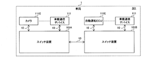
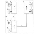
- FIG. 1 is a diagram showing a configuration of an in-vehicle communication system according to a first embodiment of the present invention.
- FIG. 2 is a diagram illustrating an application example of the in-vehicle communication system according to the first embodiment of the present invention.
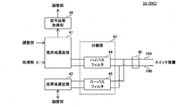
- FIG. 3 is a diagram showing a configuration of the in-vehicle communication device in the in-vehicle communication system according to the first embodiment of the present invention.
- FIG. 4 is a diagram showing a configuration of a port unit in the in-vehicle communication device according to the first embodiment of the present invention.
- FIG. 5 is a diagram illustrating an example of the mixed signal transmitted through the Ethernet cable connected between the in-vehicle communication devices according to the first embodiment of the present invention.
- FIG. 1 is a diagram showing a configuration of an in-vehicle communication system according to a first embodiment of the present invention.
- FIG. 2 is a diagram illustrating an application example of the in-vehicle communication system according to the first embodiment of
- FIG. 6 is a diagram illustrating an example of a high-band signal transmitted through the Ethernet cable in the switch device according to the first embodiment of the present invention.
- FIG. 7 is a diagram illustrating an example of a DC signal transmitted through the Ethernet cable in the switch device according to the first embodiment of the present invention.
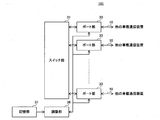
- FIG. 8 is a diagram showing a configuration of the switch device in the in-vehicle communication system according to the first embodiment of the present invention.
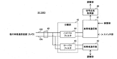
- FIG. 9 is a diagram illustrating a configuration of a port unit in the switch device according to the first embodiment of the present invention.
- FIG. 10 is a diagram showing an example of a correspondence table held by the in-vehicle communication device and the switch device according to the first embodiment of the present invention.
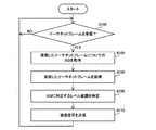
- FIG. 11 is a flowchart defining an operation procedure when the in-vehicle communication device in the in-vehicle communication system according to the first embodiment of the present invention receives an Ethernet frame.
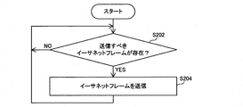
- FIG. 12 is a flowchart defining an operation procedure when the in-vehicle communication device in the in-vehicle communication system according to the first embodiment of the present invention transmits an Ethernet frame.
- FIG. 13 is a flowchart defining an operation procedure when the in-vehicle communication device in the in-vehicle communication system according to the first embodiment of the present invention receives management information.
- FIG. 14 is a diagram showing an example of a correspondence table held by the in-vehicle communication device and the switch device according to the first embodiment of the present invention.
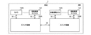
- FIG. 15 is a diagram illustrating an application example of the in-vehicle communication system according to the second embodiment of the present invention.
- FIG. 16 is a diagram showing a configuration of an in-vehicle communication device in the in-vehicle communication system according to the second embodiment of the present invention.
- FIG. 17 is a diagram showing a configuration of a switch device in the in-vehicle communication system according to the second embodiment of the present invention.
- FIG. 18 is a diagram illustrating an example of a correspondence table held by the in-vehicle communication device and the switch device according to the second embodiment of the present invention.
- FIG. 16 is a diagram showing a configuration of an in-vehicle communication device in the in-vehicle communication system according to the second embodiment of the present invention.
- FIG. 17 is a diagram showing a configuration of a switch device in the in-vehicle communication system according to the second embodiment of the present invention.
- FIG. 18 is a diagram illustrating an example of a correspondence
- FIG. 19 is a flowchart defining an operation procedure when the switch device in the in-vehicle communication system according to the second embodiment of the present invention transmits a failure confirmation request to the camera.
- FIG. 20 is a flowchart defining an operation procedure when the switch device in the in-vehicle communication system according to the second embodiment of the present invention periodically transmits a failure confirmation request to the camera.
- FIG. 21 is a diagram illustrating an application example of the in-vehicle communication system according to the third embodiment of the present invention.
- FIG. 22 is a diagram showing the configuration of the switch device in the in-vehicle communication system according to the third embodiment of the present invention.
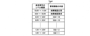
- FIG. 23 is a diagram illustrating an example of a correspondence table held by the in-vehicle communication device and the switch device according to the third embodiment of the present invention.
- FIG. 24 is a diagram illustrating an example of a disconnection determination table held by the in-vehicle communication device and the switch device according to the third embodiment of the present invention.
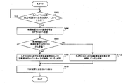
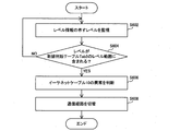
- FIG. 25 is a flowchart defining an operation procedure when the switch device in the in-vehicle communication system according to the third embodiment of the present invention switches the communication path.
- the present disclosure has been made in order to solve the above-described problem, and an object thereof is an in-vehicle communication device, an in-vehicle communication system, and a communication control method capable of efficiently transmitting information with a simple configuration in an in-vehicle network. And providing a communication control program.
- An in-vehicle communication device is an in-vehicle communication device that communicates with another in-vehicle communication device using one differential signal line, and generates a high-band signal including communication information.
- a high-band communication unit that outputs to the differential signal line, and a low-band communication unit that generates a DC signal or a low-band signal and outputs the signal to the differential signal line.
- the configuration in which the in-vehicle communication devices are connected by a single differential signal line can suppress an increase in the weight of the vehicle and can reduce the number of signal lines. Wiring can be facilitated.
- a high-band signal and a direct-current signal or a low-band signal can be output to one differential signal line, a band in which information can be transmitted on one differential signal line can be expanded. Thereby, the amount of information that can be transmitted per unit time using one differential signal line can be increased. Therefore, information can be efficiently transmitted with a simple configuration in the in-vehicle network.
- the in-vehicle communication device is an in-vehicle communication device that communicates with another in-vehicle communication device using one differential signal line, and is received via the differential signal line.
- a separation unit capable of separating a high-band signal and a direct-current signal or a low-band signal from a signal, a high-band communication unit that acquires information from the high-band signal separated by the separation unit, and the separation unit
- a low-band communication unit that acquires information from the DC signal or the low-band signal.
- the configuration in which the in-vehicle communication devices are connected by a single differential signal line can suppress an increase in the weight of the vehicle and can reduce the number of signal lines. Wiring can be facilitated.
- the band in which information can be transmitted using one differential signal line is expanded. Can do. Thereby, the amount of information that can be transmitted per unit time on one differential signal line can be increased. Therefore, information can be efficiently transmitted with a simple configuration in the in-vehicle network.
- the DC signal or the low-band signal includes management information indicating a state relating to a physical layer between the own in-vehicle communication device and another in-vehicle communication device, and the communication information includes the management information. There is no information.
- the configuration in which the management information is transmitted by being included in the DC signal or the low-band signal can prevent the band of the high-band signal transmitting the communication information from being compressed by the management information. It is possible to prevent the communication information from being delayed and dropped due to being included in the band signal. Thereby, transmission of the communication information in a vehicle-mounted network can be performed efficiently.
- the differential signal line includes two signal lines, and the DC signal is transmitted through one of the two signal lines.
- transmission of information using a DC signal or a low-band signal can be simultaneously performed between the vehicle-mounted communication devices from both directions, so that transmission is possible per unit time using the DC signal or the low-band signal.
- the amount of information can be increased.
- the management information includes communication quality between its own in-vehicle communication device and the other in-vehicle communication device.
- the in-vehicle communication device that is the transmission source of communication information can recognize the reception quality of the communication information in the in-vehicle communication device that is the transmission destination based on the management information from the in-vehicle communication device that is the transmission destination. Therefore, processing according to the recognized reception quality can be performed. Thereby, communication between vehicle-mounted communication apparatuses can be stabilized.
- the DC signal having a level corresponding to the communication quality or the low-band signal having an amplitude corresponding to the communication quality is transmitted via the differential signal line.
- management information including communication quality can be easily transmitted through one differential signal line.
- the management information includes failure diagnosis information.
- failure diagnosis information can be transmitted using a DC signal or a low-band signal, so that a failure of another in-vehicle communication device can be diagnosed without squeezing the band of the high-band signal.
- the level of the DC signal acquired by the low band communication unit is within a predetermined range, or the low band acquired by the low band communication unit
- An abnormality detection unit is provided that detects an abnormality when the amplitude of the signal is within a predetermined range.
- the differential signal line has the property that the impedance increases when it deteriorates, as described above, the abnormality is detected when the level of the DC signal or the amplitude of the low-band signal falls and falls within a predetermined range. With this configuration, it is possible to easily detect abnormality of the differential signal line.
- the DC signal or the low-band signal includes management information indicating a state regarding a physical layer between the own in-vehicle communication device and another in-vehicle communication device, and the communication information includes the management information.
- the predetermined range does not overlap with the range corresponding to the management information.
- the predetermined range does not overlap with the range corresponding to the management information, it is possible to provide the predetermined range in a range where it can be determined more reliably that there is an abnormality.
- the in-vehicle communication device when the abnormality is detected by the abnormality detection unit, the in-vehicle communication device further performs switching related to switching of communication paths between the own in-vehicle communication device and the other in-vehicle communication device.
- a processing unit is provided.
- the DC signal or the low-band signal includes management information indicating a state regarding a physical layer between the own in-vehicle communication device and another in-vehicle communication device, and the communication information includes the management information.
- the management information includes communication quality between its own in-vehicle communication device and the other in-vehicle communication device, and the in-vehicle communication device further includes the communication quality acquired by the low-band communication unit.
- an adjustment unit that adjusts the operation of the amplifier included in the high-bandwidth communication unit.
- the in-vehicle communication device that is the transmission source of communication information can recognize the reception quality of the communication information in the in-vehicle communication device that is the transmission destination based on the management information from the in-vehicle communication device that is the transmission destination. Therefore, the amplification factor of the high-band signal including communication information can be appropriately adjusted according to the recognized reception quality. Thereby, communication between in-vehicle communication devices can be stabilized and power consumption can be managed appropriately.
- the carrier frequency of the high-band signal is 10 megahertz or more.
- the DC signal and the low-band signal can be well separated, so that communication information is transmitted at high speed using the high-band signal in the in-vehicle network while stabilizing the communication in the in-vehicle network. be able to.
- the carrier frequency of the low-band signal is less than 1 megahertz.
- the communication information is an Ethernet frame conforming to IEEE 802.3.
- An in-vehicle communication system includes a first in-vehicle communication device and a second in-vehicle communication device that communicate with each other using one differential signal line, and the first in-vehicle communication.
- the apparatus generates a high-band signal including communication information and outputs the high-band signal to the differential signal line; and a low-band communication unit that generates a DC signal or a low-band signal and outputs the signal to the differential signal line
- the second in-vehicle communication device is separated by a separation unit capable of separating a high-band signal and a DC signal or a low-band signal from a signal received via the differential signal line, and the separation unit.
- the configuration in which the first in-vehicle communication device and the second in-vehicle communication device are connected by one differential signal line can suppress an increase in the weight of the vehicle, and the number of signal lines Therefore, the signal lines can be easily wired. Further, since a high-band signal and a direct-current signal or a low-band signal can be transmitted using one differential signal line, a band in which information can be transmitted on one differential signal line can be expanded. Thereby, the amount of information that can be transmitted per unit time using one differential signal line can be increased. Therefore, information can be efficiently transmitted with a simple configuration in the in-vehicle network.
- the high-band communication unit of the second in-vehicle communication device generates a high-band signal including communication information and outputs the high-band signal to the differential signal line.
- the low-band communication unit generates a DC signal or a low-band signal and outputs the DC signal or the low-band signal to the differential signal line.
- the first in-vehicle communication device further generates a high band from a signal received via the differential signal line.
- a separation unit capable of separating a signal and a DC signal or a low-band signal
- the high-band communication unit of the first in-vehicle communication device acquires information from the high-band signal separated by the separation unit
- the low-band communication unit of the first in-vehicle communication device acquires information from the DC signal or the low-band signal separated by the separation unit
- the differential signal line includes two signal lines, The low-band communication of the first in-vehicle communication device.
- the unit outputs the DC signal to one of the two signal lines, and the low-band communication unit of the second in-vehicle communication device transmits the signal to the other signal line of the two signal lines. Outputs a DC signal.
- transmission of information using a DC signal or a low-band signal can be performed simultaneously from both directions between the first in-vehicle communication device and the second in-vehicle communication device. Can be used to increase the amount of information that can be transmitted per unit time.
- the DC signal or the low-band signal includes management information indicating a state relating to a physical layer between the own in-vehicle communication device and another in-vehicle communication device, and the communication information includes the management information.
- the management information includes failure diagnosis information, and the low-bandwidth communication unit of the second in-vehicle communication device receives the failure diagnosis information from the first in-vehicle communication device and is predetermined.
- the DC signal or the low-band signal including information is output to the differential signal line, and the first in-vehicle communication device is further based on the reception status of the predetermined information from the second in-vehicle communication device.
- a diagnostic unit for diagnosing a failure of the second in-vehicle communication device is included.
- failure diagnosis information and predetermined information can be transmitted using a DC signal or a low-band signal, so that a failure of the second in-vehicle communication device can be diagnosed without squeezing the band of the high-band signal. can do.
- the first in-vehicle communication device can receive the predetermined information from the second in-vehicle communication device, for example, the processing unit and the low-band communication unit for processing the failure diagnosis information and the predetermined information in the second in-vehicle communication device Can be recognized.
- the first in-vehicle communication device cannot receive the predetermined information from the second in-vehicle communication device, for example, at least one of the processing unit and the low-band communication unit in the second in-vehicle communication device is out of order. It can be determined that the possibility is high.
- the communication information is periodically transmitted from the second in-vehicle communication device to the first in-vehicle communication device, and the first in-vehicle communication device has its own high-bandwidth communication unit.
- the high-band signal including the communication information cannot be received from the second in-vehicle communication device for a predetermined time
- the DC signal or the low-band signal including the failure diagnosis information is output to the differential signal line.
- the first in-vehicle communication device when the first in-vehicle communication device can receive the predetermined information from the second in-vehicle communication device, it can recognize that the processing unit is operating, and thus cannot receive the communication information. It can be determined that there is a high possibility that the cause is a failure of the high-bandwidth communication unit in the second in-vehicle communication device. Further, since the failure diagnosis information can be transmitted to the second in-vehicle communication device in a situation where the second in-vehicle communication device is likely to be out of order, the second in-vehicle communication device is out of order. Therefore, it is possible to prevent unnecessary transmission of failure diagnosis information in a situation where there is a low possibility of the failure being detected.
- the first in-vehicle communication device periodically outputs the DC signal or the low-band signal including the failure diagnosis information to the differential signal line, and the diagnosis unit When the predetermined information cannot be received from the second in-vehicle communication device for a predetermined time, it is determined that the second in-vehicle communication device has failed.
- the first in-vehicle communication device can periodically determine the presence or absence of a failure in the second in-vehicle communication device, so that the failure of the second in-vehicle communication device can be found earlier. Can do.
- a communication control method is a communication control method in an in-vehicle communication device that communicates with another in-vehicle communication device using one differential signal line, and includes a high-band including communication information Generating a signal and outputting the signal to the differential signal line; and generating a DC signal or a low-band signal and outputting the signal to the differential signal line.
- the configuration in which the in-vehicle communication devices are connected by a single differential signal line can suppress an increase in the weight of the vehicle and can reduce the number of signal lines. Wiring can be facilitated.
- a high-band signal and a direct-current signal or a low-band signal can be output to one differential signal line, a band in which information can be transmitted on one differential signal line can be expanded. Thereby, the amount of information that can be transmitted per unit time using one differential signal line can be increased. Therefore, information can be efficiently transmitted with a simple configuration in the in-vehicle network.
- a communication control method is a communication control method in an in-vehicle communication device that communicates with another in-vehicle communication device using one differential signal line, and the differential signal line Separating a high-band signal and a direct-current signal or a low-band signal from a signal received via the signal, obtaining information from the separated high-band signal, and information from the separated direct-current signal or the low-band signal. Acquiring.
- the configuration in which the in-vehicle communication devices are connected by a single differential signal line can suppress an increase in the weight of the vehicle and can reduce the number of signal lines. Wiring can be facilitated.
- the band in which information can be transmitted using one differential signal line is expanded. Can do. Thereby, the amount of information that can be transmitted per unit time on one differential signal line can be increased. Therefore, information can be efficiently transmitted with a simple configuration in the in-vehicle network.
- a communication control program is a communication control program used in an in-vehicle communication device that communicates with another in-vehicle communication device using one differential signal line, and the in-vehicle communication device A high-band communication unit that generates a high-band signal including communication information and outputs the high-band signal to the differential signal line; and a low-band communication unit that generates a DC signal or a low-band signal and outputs the signal to the differential signal line; And a computer for functioning as a first transmission processing unit for transmitting information via the high-bandwidth communication unit and a second transmission processing unit for transmitting information via the low-bandwidth communication unit It is a program.
- the configuration in which the in-vehicle communication devices are connected by a single differential signal line can suppress an increase in the weight of the vehicle and can reduce the number of signal lines. Wiring can be facilitated.
- a high-band signal and a direct-current signal or a low-band signal can be output to one differential signal line, a band in which information can be transmitted on one differential signal line can be expanded. Thereby, the amount of information that can be transmitted per unit time using one differential signal line can be increased. Therefore, information can be efficiently transmitted with a simple configuration in the in-vehicle network.
- a communication control program is a communication control program used in an in-vehicle communication device that communicates with another in-vehicle communication device using one differential signal line
- the in-vehicle communication device Is a separation unit capable of separating a high-band signal and a direct-current signal or a low-band signal from a signal received via the differential signal line, and a high unit for acquiring information from the high-band signal separated by the separation unit.
- a band communication unit, and a low-band communication unit that acquires information from the DC signal or the low-band signal separated by the separation unit, and a computer receives information via the high-band communication unit.
- This is a program for functioning as a reception processing unit and a second reception processing unit that receives information via the low-band communication unit.
- the configuration in which the in-vehicle communication devices are connected by a single differential signal line can suppress an increase in the weight of the vehicle and can reduce the number of signal lines. Wiring can be facilitated.
- the band in which information can be transmitted using one differential signal line is expanded. Can do. Thereby, the amount of information that can be transmitted per unit time on one differential signal line can be increased. Therefore, information can be efficiently transmitted with a simple configuration in the in-vehicle network.
- FIG. 1 is a diagram showing a configuration of an in-vehicle communication system according to a first embodiment of the present invention.
- the in-vehicle communication system 301 includes switch devices 101A and 101B and a plurality of in-vehicle communication devices 111.
- each of the switch devices 101A and 101B is also referred to as a switch device 101.
- the in-vehicle communication system 301 is mounted on the vehicle 1.
- the switch device 101 and the in-vehicle communication device 111 are examples of the in-vehicle communication device.
- the in-vehicle communication system 301 is not limited to a configuration including three or more in-vehicle communication devices, and may be configured to include two in-vehicle communication devices. Specifically, the in-vehicle communication system 301 may be configured by the two switch devices 101, the in-vehicle communication system 301 may be configured by the two in-vehicle communication devices 111, one switch device 101, and one The in-vehicle communication device 301 may be configured by the in-vehicle communication device 111.
- the in-vehicle communication device 111 is, for example, a TCU (Telematics Communication Unit), a central gateway, a human machine interface, a camera, a sensor, an automatic driving ECU, a navigation device, and the like, and can communicate with the switch device 101.
- TCU Transmission Control Unit
- central gateway a human machine interface
- camera a camera
- sensor a sensor
- automatic driving ECU a navigation device
- the switch device 101 can communicate with the switch device 101.
- the TCU can perform wireless communication with a wireless base station device (not shown) and can communicate with the switch device 101 according to a communication standard such as LTE (Long Term Evolution) or 3G.
- a communication standard such as LTE (Long Term Evolution) or 3G.
- the central gateway can communicate with a control device such as an engine control unit via a CAN (Controller Area Network), and can communicate with the switch device 101, for example.
- a control device such as an engine control unit via a CAN (Controller Area Network)
- CAN Controller Area Network
- the central gateway performs relay processing of information exchanged between the control device and the other in-vehicle communication device 111.
- connection relationship between the switch devices 101A and 101B and each in-vehicle communication device 111 in the in-vehicle network of the vehicle 1 is fixed, for example.
- the switch devices 101A and 101B are connected to each other by an in-vehicle Ethernet (registered trademark) communication cable (hereinafter also referred to as an Ethernet cable) 10 which is an example of a differential signal line.
- an Ethernet cable 10 which is an example of a differential signal line.
- the switch apparatus 101 is connected with the vehicle-mounted communication device 111 by the Ethernet cable 10, for example. Details of the differential signal line will be described later.
- Each in-vehicle communication device communicates with each other using one differential signal line. Specifically, the in-vehicle communication device communicates with another in-vehicle communication device using, for example, the Ethernet cable 10.
- the switch devices 101A and 101B communicate with each other using the Ethernet cable 10.
- the switch device 101 and the in-vehicle communication device 111 directly connected to the switch device 101 communicate with each other using the Ethernet cable 10.
- Information is exchanged between the switch device 101 and other in-vehicle communication devices directly connected to the switch device 101 using, for example, an Ethernet frame according to IEEE 802.3.
- the in-vehicle communication device 111 transmits an Ethernet frame to another in-vehicle communication device 111 via one or a plurality of switch devices 101.
- the Ethernet frame includes, for example, the MAC address of the in-vehicle communication device 111 and the MAC address of the other in-vehicle communication device 111 as a source MAC (Media Access Control) address and a destination MAC address, respectively.
- MAC Media Access Control
- FIG. 2 is a diagram showing an application example of the in-vehicle communication system according to the first embodiment of the present invention.
- FIG. 2 shows a camera 111C and an automatic driving ECU 111E as specific examples of the in-vehicle communication device 111.
- the camera 111C is connected to the switch device 101A.
- the automatic operation ECU 111E is connected to the switch device 101B.
- the camera 111C transmits an Ethernet frame including image information to the automatic operation ECU 111E via the switch devices 101A and 101B.
- the source and destination of the Ethernet frame are not limited to the in-vehicle communication device 111 such as the camera 111C and the automatic operation ECU 111E, but may be the switch device 101.
- the following Ethernet frame is transmitted in addition to the above Ethernet frame.
- the sensor transmits an Ethernet frame including the sensing result to the automatic operation ECU 111E via one or more switch devices 101.
- the TCU receives moving image information, audio information, map information, and the like from the radio base station, and transmits an Ethernet frame including the received information to the navigation device via one or more switch devices 101.
- the switch device 101 is specifically a layer 2 (L2) switch.
- L2 layer 2
- the switch device 101 refers to the destination MAC address included in the received Ethernet frame, and responds to the referenced destination MAC address.
- the relay processing for transmitting the Ethernet frame to the other switch device 101 or the destination in-vehicle communication device 111 is performed.
- FIG. 3 is a diagram showing a configuration of the in-vehicle communication device in the in-vehicle communication system according to the first embodiment of the present invention.
- the in-vehicle communication device 111 includes a port unit 33, an adjustment unit (second transmission processing unit and second reception processing unit) 36, a storage unit 37, and a processing unit (first transmission).
- a processing unit and a first reception processing unit) 38 includes a port unit 33, an adjustment unit (second transmission processing unit and second reception processing unit) 36, a storage unit 37, and a processing unit (first transmission).
- a processing unit and a first reception processing unit) 38 includes a port unit 33, an adjustment unit (second transmission processing unit and second reception processing unit) 36, a storage unit 37, and a processing unit (first transmission).
- a processing unit and a first reception processing unit) 38 includes a port unit 33, an adjustment unit (second transmission processing unit and second reception processing unit) 36, a storage unit 37, and a processing unit (first transmission).
- the operation of the camera 111C will be described as an example of the operation of the in-vehicle communication device 111, but the operation of the in-vehicle communication device 111 such as a TCU, a central gateway, a human machine interface, a sensor, an automatic operation ECU 111E, and a navigation device is the same. .
- the camera 111C captures an image around the vehicle 1 and creates image information indicating the captured image.
- the camera 111C transmits the created image information and an Ethernet frame including the MAC address of the automatic operation ECU 111E as the destination MAC address to the automatic operation ECU 111E via the switch devices 101A and 101B.
- the port unit 33 in the camera 111C is connected to one other in-vehicle communication device, here the switch device 101A, via the Ethernet cable 10.
- the processing unit 38 creates, for example, an Ethernet frame that includes photographed image information and that is destined for the automatic operation ECU 111E, and outputs the created Ethernet frame to the port unit 33.
- the port unit 33 When the port unit 33 receives the Ethernet frame from the processing unit 38, the port unit 33 processes the received Ethernet frame, and transmits the processed Ethernet frame to the switch device 101A via the Ethernet cable 10.
- the port unit 33 receives an Ethernet frame from the switch device 101A via the Ethernet cable 10, the port unit 33 processes the received Ethernet frame and outputs the processed Ethernet frame to the processing unit 38. Details of the operation of the port unit 33 will be described later.
- FIG. 4 is a diagram showing a configuration of a port unit in the in-vehicle communication device according to the first embodiment of the present invention.
- the port unit 33 includes a connector 40, a high-band communication unit 41, a low-band communication unit 42, a separation unit 43, and a signal quality acquisition unit 46.
- Separation unit 43 includes a high-pass filter 44 and a low-pass filter 45.
- the connector 40 in the port unit 33 can be connected to the Ethernet cable 10.
- the Ethernet cable 10 is, for example, a UTP (Unshielded Twisted Pair) cable and includes signal lines 10A and 10B.
- the Ethernet cable 10 can transmit, for example, a high-band signal and a DC signal according to a communication standard such as 100BASE-T1 and 1000BASE-T1.
- being able to transmit a high-band signal and a direct-current signal means that it is possible to transmit a high-band signal and a direct-current signal simultaneously, and either a high-band signal or a direct-current signal is transmitted. In some cases, In either case, the transmission target signal is transmitted through the Ethernet cable 10. Further, the carrier frequency of the high-band signal is, for example, 10 megahertz or more.
- FIG. 5 is a diagram illustrating an example of a mixed signal transmitted through the Ethernet cable connected between the in-vehicle communication devices according to the first embodiment of the present invention.
- the horizontal axis indicates time, and the vertical axis indicates level.
- FIG. 5 shows the time change of the voltage difference between the signal lines 10A and 10B in the Ethernet cable 10.
- This voltage difference is the level of the mixed signal Sm in which the high-band signal and the DC signal are mixed.
- the mixed signal Sm includes a DC signal having a level of 2 volts and a high-band signal oscillating between +1 volt and ⁇ 1 volt.
- FIG. 6 is a diagram illustrating an example of a high-band signal transmitted through the Ethernet cable in the switch device according to the first embodiment of the present invention. 6 is the same as FIG.
- the separation unit 43 can separate the high-band signal and the DC signal from the signal received through the differential signal line.
- the high-pass filter 44 in the separation unit 43 attenuates a component having a frequency equal to or lower than a predetermined frequency among the frequency components of the electrical signal passing through itself.
- the high-pass filter 44 attenuates a direct current signal among the mixed signal Sm received from one other in-vehicle communication device, here the switch device 101A via the Ethernet cable 10 and the connector 40, and has a high bandwidth.
- the signal Sh is passed.
- FIG. 7 is a diagram illustrating an example of a DC signal transmitted through the Ethernet cable in the switch device according to the first embodiment of the present invention. 7 is the same as FIG.
- the low-pass filter 45 attenuates a component having a frequency equal to or higher than a predetermined frequency among the frequency components of the electric signal passing through itself.
- the low-pass filter 45 attenuates the high-band signal Sh out of the mixed signal Sm received through the Ethernet cable 10 and the connector 40 from one other in-vehicle communication device, here the switch device 101A, and The DC signal Sd is passed.
- FIG. 8 is a diagram showing a configuration of the switch device in the in-vehicle communication system according to the first embodiment of the present invention.
- switch device 101 includes a switch unit (first transmission processing unit and first reception processing unit) 31, a plurality of port units 33, and an adjustment unit (second transmission processing unit and first transmission unit). 2 reception processing unit) 36 and a storage unit 37. A unique port number is assigned to the port unit 33.
- the switch unit 31 operates as, for example, an L2 switch, and when receiving an Ethernet frame from the port unit 33, refers to a destination MAC address included in the received Ethernet frame.
- the switch unit 31 holds, for example, an ARL (Address Resolution Logic) table indicating the correspondence between the destination MAC address and the port number of the port unit 33 of the output destination.
- ARL Address Resolution Logic
- the contents of the ARL table are determined in advance by the user, for example, based on the connection relationship fixed as described above.
- the switch unit 31 acquires a port number corresponding to the referred destination MAC address from the ARL table, and receives the received Ethernet frame via the port unit 33 corresponding to the acquired port number to another switch device 101 or the in-vehicle communication device 111. Send to.
- the switch unit 31 may be configured to operate as a layer 3 (L3) switch.
- FIG. 9 is a diagram illustrating a configuration of a port unit in the switch device according to the first embodiment of the present invention.
- the port unit 33 includes a connector 40, a high-band communication unit 41, a low-band communication unit 42, a separation unit 43, and a signal quality acquisition unit 46.
- Separation unit 43 includes a high-pass filter 44 and a low-pass filter 45.
- the port unit 33 in the switch device 101A and connected to the camera 111C via the Ethernet cable 10 is also referred to as a port unit 33S.
- the port portion 33 (see FIG. 4) in the camera 111C is also referred to as a port portion 33C.
- the operation of the switch device 101A will be described as an example, but the operation of the switch device 101B is the same.
- the second end of the Ethernet cable 10 whose first end is connected to the camera 111C is connected to the connector 40 in the port section 33S.
- the high-band communication unit 41 in the port unit 33C of the camera 111C generates a high-band signal including communication information and outputs it to the differential signal line. More specifically, the high band communication unit 41 outputs a high band signal to the signal line 10 ⁇ / b> A in the Ethernet cable 10, for example.
- the communication information is information that does not include, for example, management information indicating a state relating to a physical layer between the own in-vehicle communication device and another in-vehicle communication device.
- the communication information is an Ethernet frame including image information, for example.
- full-duplex communication of high-band signals is performed between the camera 111C and the switch device 101A.
- the high-band communication unit 41 in the port unit 33C outputs, for example, a high-band signal (hereinafter also referred to as a high-band transmission signal) from its camera 111C to the switch device 101A to the signal line 10A.
- a hybrid circuit capable of extracting from the signal line 10B a high-band signal (hereinafter also referred to as a high-band reception signal) from the switch device 101A transmitted to the camera 111C through the signal line 10B. have.
- the high-bandwidth communication unit 41 converts a bit string indicating the received Ethernet frame into a symbol string in accordance with a predetermined modulation method.
- the high-band communication unit 41 generates a high-band signal having a level corresponding to the symbol, that is, a high-band transmission signal in order from the first symbol in the converted symbol string, and uses the hybrid circuit to generate the generated high-band transmission.
- the signal is output to the signal line 10A via the high pass filter 44.
- the high-pass filter 44 since the high-band transmission signal does not include a direct-current signal, the high-pass filter 44 hardly receives an attenuation action in the high-pass filter 44 and is transmitted to the switch device 101A via the connector 40 and the Ethernet cable 10.
- the high band communication unit 41 in the port unit 33S of the switch device 101A acquires communication information from the high band signal separated by the separation unit 43.
- the high-band communication unit 41 outputs, for example, a high-band signal from the switch device 101A to the camera 111C, that is, a high-band transmission signal, to the signal line 10B, and from the camera 111C to the switch device 101A.
- the high-frequency signal that is, the high-band received signal, can be taken out from the signal line 10A.
- the high-band communication unit 41 uses a hybrid circuit to acquire a high-band signal transmitted from the camera 111C via the signal line 10A and passed through the high-pass filter 44, that is, a high-band received signal.
- the high-band communication unit 41 generates a symbol string by demodulating the high-band received signal according to a predetermined modulation method, and converts the generated symbol string into a bit string.
- the converted bit string indicates an Ethernet frame.
- the high bandwidth communication unit 41 outputs a bit string, that is, an Ethernet frame, to the switch unit 31.
- the switch unit 31 when the switch unit 31 receives the Ethernet frame from the port unit 33S, the switch unit 31 transmits the received Ethernet frame to the switch device 101B via the port unit 33 connected to the switch device 101B.
- switch device 101B when receiving the Ethernet frame from switch device 101A, switch device 101B relays the received Ethernet frame and transmits it to automatic operation ECU 111E.
- the automatic operation ECU 111E When the automatic operation ECU 111E receives the Ethernet frame including the image information from the switch device 101B, the automatic operation ECU 111E transmits, for example, the Ethernet frame including the ACK indicating the reception confirmation and including the MAC address of the camera 111C as the destination MAC address to the switch device 101B.
- the switch device 101B When the switch device 101B receives the Ethernet frame from the automatic operation ECU 111E, the switch device 101B relays the received Ethernet frame and transmits it to the switch device 101A.
- the switch unit 31 when the switch unit 31 receives an Ethernet frame from the switch device 101B via the port unit 33 connected to the switch device 101B, the switch unit 31 outputs the received Ethernet frame to the port unit 33S.
- the high-band communication unit 41 in the port unit 33S of the switch device 101A receives the Ethernet frame from the switch unit 31, it generates a high-band signal including the received Ethernet frame and generates a differential signal line. Output to.
- the high band communication unit 41 outputs a high band signal to the signal line 10B in the Ethernet cable 10, for example.
- the high-bandwidth communication unit 41 converts, for example, a bit string indicating an Ethernet frame received from the switch unit 31 into a symbol string in accordance with a predetermined modulation method.
- the high-band communication unit 41 generates a high-band signal having a level corresponding to the symbol, that is, a high-band transmission signal in order from the first symbol in the converted symbol string, and uses the hybrid circuit to generate the generated high-band transmission.
- the signal is output to the signal line 10B via the high pass filter 44.
- the high-band transmission signal is transmitted to the camera 111C via the high-pass filter 44, the connector 40, and the Ethernet cable 10.
- the high band communication unit 41 in the port unit 33C of the camera 111C acquires communication information from the high band signal separated by the separation unit 43.
- the high-band communication unit 41 uses a hybrid circuit to transmit a high-band signal transmitted from the switch device 101A via the signal line 10B and passed through the high-pass filter 44, that is, a high-band received signal. To get.
- the high-band communication unit 41 generates a symbol string by demodulating the high-band received signal according to a predetermined modulation method, and converts the generated symbol string into an Ethernet frame including a bit string, that is, an ACK.
- the high bandwidth communication unit 41 outputs the Ethernet frame to the processing unit 38.
- the processing unit 38 receives the Ethernet frame from the port unit 33C, based on the ACK included in the received Ethernet frame, the image information transmitted by itself successfully reaches the automatic operation ECU 111E. Recognize that.
- the switch device 101A notifies the camera 111C of the reception quality of the high-band signal received from the camera 111C using the DC signal. Further, the camera 111C notifies the switch device 101A of the reception quality of the high-band signal received from the switch device 101A using a DC signal.
- the signal quality acquisition unit 46 in the port unit 33S of the switch device 101A acquires the signal quality of the high-band received signal.
- the signal quality acquisition unit 46 acquires SQI (Signal Quality Indicator) indicating the reception quality of the high-band received signal in the high-band communication unit 41.
- SQI Signal Quality Indicator
- the acquisition of SQI is performed, for example, every time the high-bandwidth communication unit 41 receives one Ethernet frame.
- the SQI acquisition may be performed every time the high bandwidth communication unit 41 receives a plurality of Ethernet frames.
- the SQI is represented by an integer value of 16 levels from 1 to 16, for example.
- the signal quality acquisition unit 46 outputs SQI information indicating the acquired SQI to the adjustment unit 36.
- FIG. 10 is a diagram showing an example of a correspondence table held by the in-vehicle communication device and the switch device according to the first embodiment of the present invention.
- the correspondence table Tab1 shows the correspondence between the level range of the DC signal and the contents of the management information.
- the correspondence table Tab1 is stored in the storage unit 37, for example.
- the SQI value has a value corresponding to, for example, a bit error rate (BER) value.
- BER bit error rate
- the communication quality is good.
- the SQI value is 6 to 11 (hereinafter, this range is also referred to as a normal range)
- the communication quality is normal.
- the SQI value is 12 to 16 (hereinafter, this range is also referred to as an adjustment required range)
- the communication quality is poor.
- adjustment unit 36 in switch device 101A upon receiving SQI information from signal quality acquisition unit 46 in port unit 33S, adjustment unit 36 in switch device 101A refers to correspondence table Tab1 (see FIG. 10) held in storage unit 37.
- the level range of the DC signal corresponding to the SQI indicated by the SQI information is acquired.
- the adjustment unit 36 specifies 1.5V to 2.0V as the level range of the DC signal including the value. Then, adjustment unit 36 outputs, for example, a 1.75V DC signal transmission command, which is an intermediate voltage of 1.5V to 2.0V, to port unit 33S. This transmission command is an example of management information to be described later.
- the low-band communication unit 42 in the port unit 33S generates, for example, a DC signal including management information and outputs it to the differential signal line. More specifically, the low-band communication unit 42 outputs a DC signal to one signal line in the Ethernet cable 10, here the signal line 10B.
- the management information includes, for example, communication quality between the own switch device 101A and the camera 111C.
- full-duplex communication of a DC signal is performed between the switch device 101A and the camera 111C.
- the low-band communication unit 42 in the port unit 33S outputs, for example, a DC signal (hereinafter also referred to as a DC transmission signal) from the switch device 101A to the camera 111C to the signal line 10B, and the signal line 10A as described later.
- a DC signal hereinafter also referred to as a DC transmission signal
- a hybrid circuit capable of taking out from the signal line 10A a DC signal (hereinafter also referred to as a DC reception signal) from the camera 111C to the switch device 101A transmitted through the camera 111C.
- a DC signal at a level corresponding to the communication quality is transmitted through the differential signal line.
- the low-band communication unit 42 when the low-band communication unit 42 receives a transmission command from the adjustment unit 36, the low-band communication unit 42 generates a DC signal according to the received transmission command.
- the low-band communication unit 42 includes, for example, a DA (digital-analog) converter and an AD (analog-digital) converter.
- the low-band communication unit 42 uses a DA converter to generate a DC signal at a level corresponding to the transmission command.
- This DC signal level indicates management information.
- the low-band communication unit 42 generates a DC signal of 1.75V, for example.
- the low-band communication unit 42 outputs the generated DC signal to the signal line 10B via the low-pass filter 45 using a hybrid circuit.
- the DC signal does not include a high-band signal, the direct-current signal is hardly affected by the low-pass filter 45 and is transmitted to the camera 111C via the connector 40 and the Ethernet cable 10.
- the low-band communication unit 42 in the port unit 33C of the camera 111C acquires information from the DC signal separated by the separation unit 43.
- the low-band communication unit 42 outputs, for example, a DC signal from the camera 111C to the switch device 101A, that is, a DC transmission signal, to the signal line 10A, and a DC signal from the switch device 101A to the camera 111C.
- a hybrid circuit that can take out a signal, that is, a DC reception signal from the signal line 10B is provided.
- the low-band communication unit 42 uses a hybrid circuit to acquire a DC signal transmitted from the switch device 101A via the signal line 10B and passed through the low-pass filter 45, that is, a DC reception signal.
- the low-band communication unit 42 includes, for example, a DA converter and an AD converter similarly to the low-band communication unit 42 in the port unit 33S.
- the low-band communication unit 42 uses an AD converter to detect the level of the DC reception signal, for example, every predetermined sampling period. This sampling period is greater than the reciprocal of the carrier frequency of the high-band signal.
- the low-band communication unit 42 outputs level information that is an example of management information indicating the detected level to the adjustment unit 36.
- the signal quality acquisition unit 46 acquires the SQI indicating the reception quality of the high-band received signal in the high-band communication unit 41, and outputs the SQI information indicating the acquired SQI to the adjustment unit 36.
- the adjustment unit 36 in the camera 111C adjusts the operation of the amplifier included in the high-band communication unit 41 according to the communication quality acquired by the low-band communication unit 42, for example.
- the adjustment unit 36 when receiving the level information from the low-band communication unit 42, the adjustment unit 36 refers to the correspondence table Tab1 (see FIG. 10) held by the storage unit 37 and includes the level indicated by the received level information. Specify the level range.
- the adjustment unit 36 specifies 1.5V to 2.0V as the level range in which the level is included.
- the adjustment unit 36 acquires 2, which is the SQI value corresponding to the specified level range.
- the value of this SQI is the reception quality in the switch device 101A.
- the adjustment unit 36 recognizes that the reception quality in the switching device 101A is good based on the SQI value, that is, 2 being included in the good range, and maintains the amplifier in the high-band communication unit 41.
- the adjustment unit 36 When the adjustment unit 36 receives the SQI information from the signal quality acquisition unit 46 in the port unit 33C, the adjustment unit 36 refers to the correspondence table Tab1 (see FIG. 10) held by the storage unit 37, and performs direct current corresponding to the SQI indicated by the SQI information. Get the level range of the signal.
- the adjustment unit 36 specifies 8.0V to 8.5V as the level range of the DC signal including the value. Then, adjustment unit 36 outputs, for example, a command to transmit a 8.25V DC signal, which is an intermediate voltage of 8.0V to 8.5V, to port unit 33C.
- the low-band communication unit 42 in the port unit 33C generates, for example, a DC signal including management information and outputs it to the other signal line in the Ethernet cable 10, in this case, the signal line 10A.
- the low-band communication unit 42 when the low-band communication unit 42 receives a transmission command from the adjustment unit 36, the low-band communication unit 42 generates a DC signal according to the received transmission command.
- the low-band communication unit 42 uses a DA converter to generate a DC signal at a level corresponding to the transmission command.
- the low-band communication unit 42 generates, for example, a DC signal of 8.25V.
- the low-band communication unit 42 outputs the generated DC signal to the signal line 10A via the low-pass filter 45 using a hybrid circuit.
- the DC signal is transmitted to the switch device 101A via the low-pass filter 45, the connector 40, and the Ethernet cable 10.
- the low-band communication unit 42 in the port unit 33S of the switch device 101A acquires information from the DC signal separated by the separation unit 43.
- the low-band communication unit 42 uses a hybrid circuit to acquire a DC signal transmitted from the camera 111C via the signal line 10A and passed through the low-pass filter 45, that is, a DC reception signal.
- the low-band communication unit 42 detects the level of the acquired DC reception signal using an AD converter, similarly to the low-band communication unit 42 in the port unit 33C.
- the low-band communication unit 42 outputs level information that is an example of management information indicating the detected level to the adjustment unit 36.
- the adjustment unit 36 in the switching device 101A receives the level information from the low-band communication unit 42
- the adjustment unit 36 refers to the correspondence table Tab1 (see FIG. 10) held by the storage unit 37 and receives the received level. Specify the level range that includes the level indicated by the information.
- the adjustment unit 36 specifies 8.0V to 8.5V as the level range in which the level is included.
- the adjustment unit 36 acquires SQI value 15 corresponding to the specified level range.
- the value of this SQI is the reception quality at the camera 111C.
- the adjustment unit 36 recognizes that the reception quality in the camera 111C is poor based on the SQI value, that is, 15 included in the adjustment required range, and adjusts the amplifier in the high-band communication unit 41.
- the adjustment unit 36 increases the gain of the amplifier in the high-band communication unit 41, and increases the reception intensity in the camera 111C of the high-band signal transmitted by its switch device 101A.
- the adjustment unit 36 may adjust the cutoff frequency in the active filter in accordance with an increase in the gain of the amplifier.
- the transmission of the high-band signal and the DC signal between the in-vehicle communication device 111 and the switch device 101 has been described in detail using the camera 111C and the switch device 101A as an example, but the high-band signal and the DC signal between the two switch devices 101 have been described in detail.
- the signal transmission is the same as that between the in-vehicle communication device 111 and the switch device 101.
- Each device in the in-vehicle communication system 301 includes a computer, and an arithmetic processing unit such as a CPU in the computer reads and executes a program including a part or all of each step of the following sequence diagram or flowchart from a memory (not shown). To do.
- Each of the programs of the plurality of apparatuses can be installed from the outside. The programs of the plurality of apparatuses are distributed while being stored in a recording medium.
- FIG. 11 is a flowchart defining an operation procedure when the in-vehicle communication device in the in-vehicle communication system according to the first embodiment of the present invention receives an Ethernet frame.
- the in-vehicle communication device waits until an Ethernet frame is received from another in-vehicle communication device via high band communication unit 41 (NO in step S102).
- the in-vehicle communication device acquires SQI for the received Ethernet frame (step S104).
- the in-vehicle communication device processes the received Ethernet frame (step S106).
- the in-vehicle communication device specifies the level range of the DC signal corresponding to the acquired SQI based on the correspondence table Tab1 (see FIG. 10) (step S108).
- the in-vehicle communication device transmits a DC signal having an intermediate voltage in the specified level range to the other in-vehicle communication device via the low-band communication unit 42 (step S110).
- the in-vehicle communication device waits until a new Ethernet frame is received from the other in-vehicle communication device via the high-band communication unit 41 (NO in step S102).
- the in-vehicle communication device when the in-vehicle communication device is the switch device 101, the in-vehicle communication device performs transfer processing of the received Ethernet frame in step S106.
- step S106 and the steps S108 and S110 is not limited to the above, and the order may be changed.
- FIG. 12 is a flowchart defining an operation procedure when the in-vehicle communication device in the in-vehicle communication system according to the first embodiment of the present invention transmits an Ethernet frame.
- the in-vehicle communication device waits if there is no Ethernet frame to be transmitted (NO in step S202).
- the in-vehicle communication device transmits the Ethernet frame via the high bandwidth communication unit 41 (step S204).
- the in-vehicle communication device waits if there is no new Ethernet frame to be transmitted (NO in step S202).
- FIG. 13 is a flowchart defining an operation procedure when the in-vehicle communication device in the in-vehicle communication system according to the first embodiment of the present invention receives management information.
- the in-vehicle communication device waits until a predetermined sampling timing arrives (NO in step S302).
- the in-vehicle communication device detects the level of the DC signal received via the low-band communication unit 42 (step S304).
- the in-vehicle communication device acquires the SQI corresponding to the detected level based on the correspondence table Tab1 (see FIG. 10) (step S306).
- the in-vehicle communication device adjusts the amplifier in the high-band communication unit 41 (step S310).
- the in-vehicle communication device waits until a new sampling timing arrives (NO in step S302).
- the low-band communication unit 42 is configured to generate a DC signal and output it to the differential signal line.
- the present invention is not limited to this. is not.
- the low-band communication unit 42 may be configured to generate a low-band signal and output it to a differential signal line.
- the low-band communication unit 42 is configured to acquire information from the DC signal separated by the separation unit 43, but the present invention is limited to this. It is not a thing.
- the low band communication unit 42 may be configured to acquire information from the low band signal separated by the separation unit 43.
- the carrier frequency of the low-band signal is, for example, less than 1 megahertz.
- the low-pass filter 45 in the separation unit 43 attenuates the high-band signal among the mixed signals received from one other in-vehicle communication device via the Ethernet cable 10 and the connector 40. And passing a low-band signal.
- FIG. 14 is a diagram showing an example of a correspondence table held by the in-vehicle communication device and the switch device according to the first embodiment of the present invention.
- the correspondence table Tab2 shows a correspondence relationship between the amplitude range of the low-band signal and the content of the management information.
- the correspondence table Tab2 is stored in the storage unit 37, for example.
- a low-band signal having an amplitude corresponding to the communication quality is transmitted via the differential signal line.
- the adjustment unit 36 when the adjustment unit 36 (see FIG. 3) in the camera 111C receives the SQI information from the signal quality acquisition unit 46 in the port unit 33C, the adjustment unit 36 refers to the correspondence table Tab2 held in the storage unit 37 and determines the SQI. The amplitude range of the low-band signal corresponding to the SQI indicated by the information is acquired.
- the adjustment unit 36 specifies 8.0 V to 8.5 V as the amplitude range of the low-band signal including the value. Then, adjustment unit 36 outputs, for example, a transmission instruction for a low-band signal having an amplitude of 8.25V, which is an intermediate voltage of 8.0V to 8.5V, to port unit 33C.
- the low-band communication unit 42 (see FIG. 4) in the port unit 33C receives the transmission command from the adjustment unit 36, the low-band signal having an amplitude corresponding to the transmission command is obtained using the DA converter according to the received transmission command. Generate.
- the amplitude of this low band signal indicates management information.
- the low-band communication unit 42 generates a low-band signal having an amplitude of 8.25 V, for example.
- the low-band communication unit 42 outputs the generated low-band signal to the signal line 10A via the low-pass filter 45 using a hybrid circuit.
- the low-band signal does not include the high-band signal, the low-band filter hardly receives the attenuation action in the low-pass filter 45 and is transmitted to the switch device 101A via the connector 40 and the Ethernet cable 10.
- the low-band communication unit 42 (see FIG. 9) in the port unit 33S of the switch device 101A is a low-band signal transmitted from the camera 111C via the signal line 10A using the hybrid circuit and passed through the low-pass filter 45. Obtain a band signal.
- the low-band communication unit 42 uses an AD converter to detect the amplitude of the acquired low-band signal, and outputs amplitude information that is an example of management information indicating the detected amplitude to the adjustment unit 36.
- the adjustment unit 36 in the switch device 101A receives the amplitude information from the low-band communication unit 42, the adjustment unit 36A refers to the correspondence table Tab2 held by the storage unit 37 and includes the amplitude included in the amplitude indicated by the received amplitude information. Identify the range.
- the adjustment unit 36 specifies 8.0 V to 8.5 V as the amplitude range including the amplitude.
- the adjustment unit 36 acquires SQI value 15 corresponding to the specified amplitude range.
- the value of this SQI is the reception quality at the camera 111C.
- the adjustment unit 36 recognizes that the reception quality in the camera 111C is poor because the SQI value, that is, 15 is included in the adjustment required range, and adjusts the amplifier in the high-band communication unit 41.
- the port unit 33 is configured to be provided inside the switch device 101.
- the port unit 33 may be configured to be provided outside the switch device 101 as an in-vehicle communication device.
- the port unit 33 is configured to be provided in the in-vehicle communication device 111.
- the port unit 33 may be configured to be provided outside the in-vehicle communication device 111 as the in-vehicle communication device.
- the in-vehicle communication devices are connected by the Ethernet cable 10, but the present invention is not limited to this.
- the in-vehicle communication devices may be connected by a cable different from the Ethernet cable 10 as long as it is a differential signal line.
- each communication path is configured to perform both high-band signal transmission and DC signal or low-band signal transmission.
- the present invention is not limited to this. A configuration in which only transmission of a high-band signal is performed on some of the communication paths is also possible.
- the DC signal or the low-band signal includes the management information
- the high-band signal includes the communication information that does not include the management information.
- the present invention is not limited to this.
- a configuration in which part of the management information is transmitted by a DC signal or a low-band signal and communication information including the remaining part of the management information is transmitted by a high-band signal may be used.
- the low-band communication unit 42 of the camera 111C outputs a DC signal to the signal line 10A in the Ethernet cable 10, and the low-band of the switch device 101A.
- the communication unit 42 is configured to output a DC signal to the signal line 10B in the Ethernet cable 10, it is not limited to this.
- the low-band communication unit 42 of the camera 111C and the low-band communication unit 42 of the switch device 101A may be configured to output DC signals to both the signal lines 10A and 10B in the Ethernet cable 10.
- the configuration may be such that half-duplex communication is performed in which one-way communication is alternately performed by assigning transmission periods to the camera 111C and the switch device 101A so as not to overlap each other.
- a DC signal having a level corresponding to communication quality or a low-band signal having an amplitude corresponding to communication quality is transmitted via a differential signal line.
- a differential signal line it is not limited to this.
- a configuration may be employed in which a DC signal that is turned on / off in a pattern according to communication quality or a low-band signal that is modulated according to communication quality is transmitted via a differential signal line.
- the adjustment unit 36 is included in the high-band communication unit 41 according to the communication quality between the own in-vehicle communication device and other in-vehicle communication devices.
- the adjustment unit 36 may be configured to adjust the communication speed of the high-band signal transmitted by the high-band communication unit 41 according to the communication quality.
- the carrier frequency of the high-band signal is 10 megahertz or more.
- the carrier frequency of the high band signal may be less than 10 megahertz as long as it can be separated from the direct current signal and the low band signal by the separation unit 43.
- the carrier frequency of the low-band signal is less than 1 megahertz, but the present invention is not limited to this.
- the carrier frequency of the low-band signal may be 1 megahertz or more as long as it can be separated from the high-band signal by the separation unit 43.
- the communication information is an Ethernet frame according to IEEE 802.3, but the present invention is not limited to this.
- the communication information may be, for example, a message conforming to the CAN communication standard.
- the in-vehicle communication device communicates with another in-vehicle communication device using one differential signal line.
- the high band communication unit 41 generates a high band signal including communication information and outputs it to the differential signal line.
- the low-band communication unit 42 generates a DC signal or a low-band signal and outputs it to the differential signal line.
- the configuration in which the in-vehicle communication devices are connected by a single differential signal line can suppress an increase in the weight of the vehicle 1 and can reduce the number of signal lines. Wire wiring can be facilitated.
- a high-band signal and a direct-current signal or a low-band signal can be output to one differential signal line, a band in which information can be transmitted on one differential signal line can be expanded. Thereby, the amount of information that can be transmitted per unit time using one differential signal line can be increased. Therefore, information can be efficiently transmitted with a simple configuration in the in-vehicle network.
- the in-vehicle communication device communicates with other in-vehicle communication devices using one differential signal line.
- the separation unit 43 can separate a high-band signal including communication information and a direct-current signal or a low-band signal from a signal received via a differential signal line.
- the high band communication unit 41 acquires communication information from the high band signal separated by the separation unit 43.
- the low band communication unit 42 acquires information from the DC signal or the low band signal separated by the separation unit 43.
- the configuration in which the in-vehicle communication devices are connected by a single differential signal line can suppress an increase in the weight of the vehicle 1 and can reduce the number of signal lines. Wire wiring can be facilitated.
- the band in which information can be transmitted using one differential signal line is expanded. Can do. Thereby, the amount of information that can be transmitted per unit time on one differential signal line can be increased. Therefore, information can be efficiently transmitted with a simple configuration in the in-vehicle network.
- the DC signal or the low-band signal includes management information indicating a state regarding a physical layer between the own in-vehicle communication device and another in-vehicle communication device.
- the communication information is information that does not include management information.
- the configuration in which the management information is transmitted by being included in the DC signal or the low-band signal can prevent the band of the high-band signal transmitting the communication information from being compressed by the management information. It is possible to prevent the communication information from being delayed and dropped due to being included in the band signal. Thereby, transmission of the communication information in a vehicle-mounted network can be performed efficiently.
- the differential signal lines include signal lines 10A and 10B.
- the DC signal is transmitted via one of the signal lines 10A and 10B.
- transmission of information using a DC signal or a low-band signal can be simultaneously performed between the vehicle-mounted communication devices from both directions, so that transmission is possible per unit time using the DC signal or the low-band signal.
- the amount of information can be increased.
- the management information includes communication quality between the own in-vehicle communication device and other in-vehicle communication devices.
- the in-vehicle communication device that is the transmission source of communication information can recognize the reception quality of the communication information in the in-vehicle communication device that is the transmission destination based on the management information from the in-vehicle communication device that is the transmission destination. Therefore, processing according to the recognized reception quality can be performed. Thereby, communication between vehicle-mounted communication apparatuses can be stabilized.
- a DC signal having a level corresponding to the communication quality or a low-band signal having an amplitude corresponding to the communication quality is transmitted via the differential signal line.
- management information including communication quality can be easily transmitted through one differential signal line.
- the DC signal or the low-band signal includes management information indicating a state regarding a physical layer between the own in-vehicle communication device and another in-vehicle communication device.
- the communication information is information that does not include management information.
- the management information includes communication quality between the own in-vehicle communication device and other in-vehicle communication devices. Then, the adjustment unit 36 adjusts the operation of the amplifier included in the high band communication unit 41 in accordance with the communication quality acquired by the low band communication unit 42.
- the in-vehicle communication device that is the transmission source of communication information can recognize the reception quality of the communication information in the in-vehicle communication device that is the transmission destination based on the management information from the in-vehicle communication device that is the transmission destination. Therefore, the amplification factor of the high-band signal including communication information can be appropriately adjusted according to the recognized reception quality. Thereby, communication between in-vehicle communication devices can be stabilized and power consumption can be managed appropriately.
- the carrier frequency of the high-band signal is 10 megahertz or more.
- the DC signal and the low-band signal can be well separated, so that communication information is transmitted at high speed using the high-band signal in the in-vehicle network while stabilizing the communication in the in-vehicle network. be able to.
- the carrier frequency of the low-band signal is less than 1 megahertz.
- the communication information is an Ethernet frame according to IEEE802.3.
- the first in-vehicle communication device and the second in-vehicle communication device communicate with each other using one differential signal line.
- the high-band communication unit 41 of the first in-vehicle communication device generates a high-band signal including communication information and outputs it to the differential signal line.
- the low-band communication unit 42 of the first in-vehicle communication device generates a DC signal or a low-band signal and outputs it to the differential signal line.
- the separation unit 43 of the second in-vehicle communication device can separate the high-band signal and the direct-current signal or the low-band signal from the signal received via the differential signal line.
- the high band communication unit 41 of the second in-vehicle communication device acquires information from the high band signal separated by the separation unit 43.
- the low-band communication unit 42 of the second in-vehicle communication device acquires information from the DC signal or the low-band signal separated by the separation unit 43.
- the configuration in which the first in-vehicle communication device and the second in-vehicle communication device are connected by one differential signal line an increase in the weight of the vehicle 1 can be suppressed. Since the number can be reduced, signal lines can be easily wired. Further, since a high-band signal and a direct-current signal or a low-band signal can be transmitted using one differential signal line, a band in which information can be transmitted on one differential signal line can be expanded. Thereby, the amount of information that can be transmitted per unit time using one differential signal line can be increased. Therefore, information can be efficiently transmitted with a simple configuration in the in-vehicle network.
- the high-band communication unit 41 of the second in-vehicle communication device generates a high-band signal including communication information and outputs it to the differential signal line.
- the low-band communication unit 42 of the second in-vehicle communication device generates a DC signal or a low-band signal and outputs it to the differential signal line.
- the separation unit 43 of the first in-vehicle communication device can separate the high-band signal and the direct-current signal or the low-band signal from the signal received via the differential signal line.
- the high band communication unit 41 of the first in-vehicle communication device acquires information from the high band signal separated by the separation unit 43.
- the low-band communication unit 42 of the first in-vehicle communication device acquires information from the DC signal or the low-band signal separated by the separation unit 43.
- the differential signal line includes signal lines 10A and 10B.
- the low-band communication unit 42 of the first in-vehicle communication device outputs a DC signal to one of the signal lines 10A and 10B.
- the low-band communication unit 42 of the second in-vehicle communication device outputs a DC signal to the other signal line of the signal lines 10A and 10B.
- transmission of information using a DC signal or a low-band signal can be performed simultaneously from both directions between the first in-vehicle communication device and the second in-vehicle communication device. Can be used to increase the amount of information that can be transmitted per unit time.
- the in-vehicle communication capable of diagnosing a failure of the in-vehicle communication device (hereinafter also referred to as the opposite device) that is opposed via the differential signal line. Relates to the device.
- the contents other than those described below are the same as those of the in-vehicle communication apparatus according to the first embodiment.
- FIG. 15 is a diagram showing an application example of the in-vehicle communication system according to the second embodiment of the present invention.
- the in-vehicle communication system 302 includes switch devices 102 ⁇ / b> A and 102 ⁇ / b> B and a plurality of in-vehicle communication devices 112.
- each of the switch devices 102A and 102B is also referred to as a switch device 102.
- the camera 112C that is the in-vehicle communication device 112 is connected to the switch device 102A.
- the automatic operation ECU 112E that is the in-vehicle communication device 112 is connected to the switch device 102B.
- the operations of the in-vehicle communication device 112 and the switch device 102 in the in-vehicle communication system 302 are the same as those of the in-vehicle communication device 111 and the switch device 101 in the in-vehicle communication system 301 shown in FIG.
- the camera 112C transmits an Ethernet frame including image information to the automatic operation ECU 112E via the switch devices 102A and 102B every predetermined time T1.
- the automatic operation ECU 112E transmits an Ethernet frame including ACK to the camera 112C via the switch devices 102B and 102A.
- FIG. 16 is a diagram showing a configuration of an in-vehicle communication device in the in-vehicle communication system according to the second embodiment of the present invention.
- the camera 112 ⁇ / b> C includes a port unit 33 ⁇ / b> C, a storage unit 37, a processing unit 38, and a diagnosis unit (second transmission processing unit and second reception processing unit) 39.
- the operations of the port unit 33C, the storage unit 37, and the processing unit 38 in the camera 112C are the same as those of the port unit 33, the storage unit 37, and the processing unit 38 in the in-vehicle communication device 111 shown in FIG.
- the port unit 33C is connected to the switch device 102A via the Ethernet cable 10 as described above.
- the configuration and operation of the camera 112C will be described as an example, but the configuration and operation of the in-vehicle communication device 112 such as a TCU, a central gateway, a human machine interface, a sensor, an automatic operation ECU 112E, and a navigation device are the same.
- the in-vehicle communication device 112 such as a TCU, a central gateway, a human machine interface, a sensor, an automatic operation ECU 112E, and a navigation device are the same.
- FIG. 17 is a diagram showing a configuration of a switch device in the in-vehicle communication system according to the second embodiment of the present invention.
- the switch device 102 ⁇ / b> A includes a switch unit 31, a plurality of port units 33, a storage unit 37, and a diagnosis unit 39.
- the operations of the switch unit 31, the port unit 33, and the storage unit 37 in the switch device 102A are the same as those of the switch unit 31, the port unit 33, and the storage unit 37 in the switch device 101 shown in FIG.
- the port unit 33S is connected to the camera 112C via the Ethernet cable 10 as described above.
- the configuration and operation of the switch device 102A will be described as an example, but the configuration and operation of the switch device 102B are the same.
- an Ethernet frame that is periodically transmitted (hereinafter also referred to as a periodic transmission frame) is registered.
- the storage unit 37 in the switch device 102A is, for example, a regular transmission frame transmitted as an example of a regular transmission frame from the camera 112C via the switch device 102A to the automatic operation ECU 112E every predetermined time T1. FC is registered.
- the diagnosis unit 39 monitors, for example, the Ethernet frame transferred by the switch unit 31 and detects that the periodic transmission frame FC is not periodically received based on the contents registered in the storage unit 37.
- the diagnosis unit 39 measures the elapsed time from the latest reception timing of the regular transmission frame FC, for example, and receives a new regular transmission frame FC even if the timeout time elapses from the latest reception timing, for example. If it is not possible, the opposite device of the switch device 102A, that is, the camera 112C is diagnosed.
- the timeout time is a time longer than the predetermined time T1.
- FIG. 18 is a diagram showing an example of a correspondence table held by the in-vehicle communication device and the switch device according to the second embodiment of the present invention.
- the correspondence table Tab3 shows the correspondence between the level range of the DC signal and the contents of the management information.
- the correspondence table Tab3 is stored in the storage unit 37, for example.
- the diagnosis unit 39 in the switch device 102A refers to the correspondence table Tab3 held by the storage unit 37 in order to confirm whether or not the camera 112C is out of order, and the failure in the correspondence table Tab3.
- the level of the DC signal corresponding to the confirmation request is specified as 9.0 V to 10.0 V.
- the failure confirmation request is an example of failure diagnosis information.
- the diagnosis unit 39 outputs, for example, a transmission command for a DC signal of 9.5 V, which is an intermediate voltage of 9.0 V to 10.0 V, to the port unit 33S.
- the low-band communication unit 42 in the port unit 33S generates, for example, a DC signal including management information including a failure confirmation request and outputs it to the differential signal line.
- the low-band communication unit 42 when the low-band communication unit 42 receives a transmission command from the diagnosis unit 39, the low-band communication unit 42 generates a DC signal according to the received transmission command using a DA converter.
- the low-band communication unit 42 outputs the generated DC signal to the signal line 10B via the low-pass filter 45 using a hybrid circuit.
- the low-band communication unit 42 in the port unit 33C of the camera 112C receives a failure confirmation request from the switch device 102A and outputs a DC signal including predetermined information to the differential signal line.
- the predetermined information is, for example, a failure confirmation response.
- the low-band communication unit 42 uses a hybrid circuit to acquire a DC signal transmitted from the switch device 102A via the signal line 10B and passed through the low-pass filter 45, that is, a DC reception signal. .
- the low-band communication unit 42 uses the AD converter to detect the level of the acquired DC reception signal and outputs level information indicating the detected level to the diagnosis unit 39.
- diagnostic unit 39 in camera 112C refers to correspondence table Tab3 (see FIG. 18) held in storage unit 37 and receives the received level information.
- the level range in which the level indicated by is included is specified.
- the diagnosis unit 39 specifies 9.0V to 10.0V as the level range in which the level is included.
- the diagnosis unit 39 confirms a failure confirmation request corresponding to the specified level range, and determines that a failure confirmation response should be transmitted to the switch device 102A.
- the diagnosis unit 39 refers to the correspondence table Tab3 held by the storage unit 37, and specifies 10.0V to 11.0V as the level range of the DC signal corresponding to the failure confirmation response in the correspondence table Tab3.
- the diagnosis unit 39 outputs, for example, a 10.5V DC signal transmission command, which is an intermediate voltage of 10.0V to 11.0V, to the port unit 33C.
- low-band communication unit 42 in port unit 33C uses a DA converter to generate a DC signal in accordance with the received transmission command.
- the low-band communication unit 42 outputs the generated DC signal to the signal line 10A via the low-pass filter 45 using a hybrid circuit.
- the low-band communication unit 42 in the port unit 33S of the switch device 102A is a DC signal transmitted from the camera 112C via the signal line 10A using the hybrid circuit and passes through the low-pass filter 45.
- the obtained DC signal, that is, the DC reception signal is acquired.
- the low-band communication unit 42 uses the AD converter to detect the level of the acquired DC reception signal and outputs level information indicating the detected level to the diagnosis unit 39.
- the diagnosis unit 39 of the switch device 102A diagnoses the failure of the camera 112C based on, for example, the reception status of the failure confirmation response from the camera 112C.
- the diagnosis unit 39 when receiving the level information from the low-band communication unit 42, the diagnosis unit 39 refers to the correspondence table Tab3 (see FIG. 18) held by the storage unit 37 and includes the level indicated by the received level information. Specify the level range.
- the diagnosis unit 39 specifies 10.0 V to 11.0 V as the level range including the level.
- the diagnosis unit 39 confirms the failure confirmation response corresponding to the specified level range, and recognizes that the diagnosis unit 39 in the camera 112C is functioning normally.
- the diagnosis unit 39 determines that it is highly likely that the reason why the periodic transmission frame FC is not periodically received is a failure of the high-band communication unit 41 in the camera 112C, and stores failure determination information indicating the determination result as a storage unit 37.
- the diagnosis unit 39 in the camera 112C when the diagnosis unit 39 in the camera 112C is not functioning normally, the diagnosis unit 39 in the switch device 102A does not receive a failure confirmation response from the camera 112C.
- the diagnosis unit 39 in the switch device 102A has a high possibility that the reason why the periodic transmission frame FC is not periodically received is a failure of either the diagnosis unit 39 or the low-band communication unit 42 in the camera 112C.
- the failure determination information indicating the determination result is stored in the storage unit 37.
- the failure determination information stored in the storage unit 37 can be transmitted to the maintenance terminal device in accordance with a communication standard such as OBD (On Board Diagnostics second generation) 2, for example.
- OBD On Board Diagnostics second generation
- the failure determination information transmitted to the maintenance terminal device can be used, for example, to identify the failure part. And the repair of the vehicle 1 in a maintenance shop can be performed simply.
- the switch device 102A transmits a failure confirmation request to the camera 112C and the camera 112C transmits a failure confirmation response to the switch device 102A.
- the camera 112C transmits a failure confirmation request to the switch device 102A. The same applies when the switch device 102A transmits a failure confirmation response to the camera 112C.
- the diagnosis unit 39 in the camera 112C diagnoses the opposite device based on, for example, that a periodic transmission frame including ACK is not periodically received.
- the diagnosis unit 39 in the camera 112C and the switch device 102A is configured to perform diagnosis of the opposite device based on the reception status of the periodic transmission frame, but is not limited thereto.
- the diagnosis unit 39 in the camera 112C and the switch device 102A may, for example, periodically transmit a failure confirmation request and diagnose the opposite device based on the periodic reception status of the failure confirmation response. Specifically, for example, when the failure confirmation response cannot be received from the opposing device for a predetermined time, the diagnosis unit 39 determines the failure of the opposing device.
- the diagnosis unit 39 in the switch device 102A sends a DC signal having a level corresponding to a failure confirmation request to the low-band communication unit 42 in the port unit 33S when a diagnosis timing for each predetermined diagnosis period arrives. Send it.
- the diagnosis unit 39 in the camera 112C sends a DC signal having a level corresponding to the failure confirmation response to the low level in the port unit 33C.
- the data is transmitted to the band communication unit 42.
- the diagnosis unit 39 and the low band communication unit 42 in the camera 112C function normally. Recognize that
- the diagnosis unit 39 in the switch device 102A does not receive a failure confirmation response from the camera 112C.
- diagnosis unit 39 in the switch device 102A cannot receive a failure confirmation response from the camera 112C for a predetermined time, it is highly likely that at least one of the diagnosis unit 39 and the low-band communication unit 42 in the camera 112C has failed.
- the failure determination information indicating the determination result is stored in the storage unit 37.
- the configuration has been described in which the diagnosis unit 39 in the switch device 102A transmits a failure confirmation request to the camera 112C at every predetermined diagnosis cycle.
- the diagnosis unit 39 in the camera 112C performs a failure confirmation request at every predetermined diagnosis cycle. The same applies to the configuration for transmitting the message to the switch device 102A.
- failure confirmation request and the transmission / reception of the failure confirmation response between the in-vehicle communication device 112 and the switch device 102 have been described in detail by taking the camera 112C and the switch device 102A as an example, but the failure confirmation request between the two switch devices 102 and The transmission / reception of the failure confirmation response is the same as that between the in-vehicle communication device 112 and the switch device 102.
- FIG. 19 is a flowchart defining an operation procedure when the switch device in the in-vehicle communication system according to the second embodiment of the present invention transmits a failure confirmation request to the camera.
- switching device 102A periodically receives periodic transmission frame FC from camera 112C.
- the switch apparatus 102A waits when a new periodic transmission frame FC can be received from the camera 112C before the timeout time elapses from the latest reception timing of the periodic transmission frame FC (YES in step S402).
- the switching device 102A When the switch device 102A fails to receive a new periodic transmission frame FC from the camera 112C before the time-out period elapses from the latest reception timing of the periodic transmission frame FC (NO in step S402), the switching device 102A performs direct current of the failure confirmation request.
- the signal is transmitted to the camera 112C via the low-band communication unit 42 (step S404).
- the switching device 102A when the switching device 102A cannot receive the DC signal of the failure confirmation response from the camera 112C via the low-band communication unit 42 (NO in step S406), the switching device 102A performs the low-band communication unit 42 and the diagnosis unit 39 of the camera 112C. It is determined that there is a high possibility that either one has failed (step S408).
- step S412 when the switching device 102A has received a DC signal of the failure confirmation response from the camera 112C via the low-band communication unit 42 (YES in step S406), the high-band communication unit 41 in the camera 112C has failed. It is determined that the possibility is high (step S412).
- the switch device 102A stores failure determination information indicating the determination result in the storage unit 37 (step S410).
- the switch device 102A has exemplified the configuration for diagnosing the failure of the camera 112C as the opposite device.
- the present invention is not limited to this. May be configured.
- FIG. 20 is a flowchart defining an operation procedure when the switch device in the in-vehicle communication system according to the second embodiment of the present invention periodically transmits a failure confirmation request to the camera.
- switch device 102A waits until a diagnosis timing for each predetermined diagnosis period arrives (NO in step S502).
- the switching device 102A transmits a DC signal for requesting failure confirmation to the camera 112C via the low-band communication unit 42 (step S504).
- the switch device 102A determines that the camera 112C is normal when the DC signal of the failure confirmation response can be received from the camera 112C within the predetermined time via the low-band communication unit 42 (YES in step S506). (Step S512).
- the switch device 102A waits until a new diagnosis timing arrives (NO in step S502).
- step S506 when the switch device 102A cannot receive the DC signal of the failure confirmation response from the camera 112C via the low-band communication unit 42 within a predetermined time (NO in step S506), the switching device 102A and the diagnosis of the low-band communication unit 42 in the camera 112C It is determined that there is a high possibility that any one of the units 39 is out of order (step S508).
- the switch device 102A stores failure determination information indicating the determination result in the storage unit 37 (step S510).
- the failure confirmation request and the failure confirmation response are included in the DC signal.
- the present invention is not limited to this.
- a configuration in which the failure confirmation request and the failure confirmation response are included in the low-band signal may be employed.
- the management information includes failure diagnosis information.
- the DC signal or the low-band signal includes management information indicating a state relating to a physical layer between the own in-vehicle communication apparatus and another in-vehicle communication apparatus.
- the communication information is information that does not include management information.
- the management information includes a failure confirmation request.
- the low-band communication unit 42 of the second in-vehicle communication device receives a failure confirmation request from the first in-vehicle communication device and outputs a DC signal or a low-band signal including a failure confirmation response to the differential signal line.
- the diagnosis part 39 in a 1st vehicle-mounted communication apparatus diagnoses the failure of a 2nd vehicle-mounted communication apparatus based on the reception condition of the failure confirmation response from a 2nd vehicle-mounted communication apparatus.
- a failure confirmation request and a failure confirmation response can be transmitted using a DC signal or a low-band signal, so that the failure of the second in-vehicle communication device can be diagnosed without squeezing the band of the high-band signal. can do.
- the processing unit that processes the failure confirmation request and the failure confirmation response in the second in-vehicle communication device and the low-band communication It can be recognized that the unit 42 is operating.
- the first in-vehicle communication device cannot receive the failure confirmation response from the second in-vehicle communication device, for example, at least one of the processing unit and the low-band communication unit 42 in the second in-vehicle communication device has failed. It can be judged that there is a high possibility.
- communication information is periodically transmitted from the second in-vehicle communication device to the first in-vehicle communication device.
- the first in-vehicle communication device 41 includes a DC signal or a low-band signal including a failure confirmation request. Is output to the differential signal line.
- the first in-vehicle communication device when the first in-vehicle communication device can receive a failure confirmation response from the second in-vehicle communication device, the first in-vehicle communication device can recognize that the processing unit is operating, and thus receives communication information. It can be determined that there is a high possibility that the cause of the failure is a failure of the high-band communication unit 41 in the second in-vehicle communication device. Further, since the failure diagnosis information can be transmitted to the second in-vehicle communication device in a situation where the second in-vehicle communication device is likely to be out of order, the second in-vehicle communication device is out of order. Therefore, it is possible to prevent unnecessary transmission of failure diagnosis information in a situation where there is a low possibility of the failure being detected.
- the first in-vehicle communication device periodically outputs a DC signal or a low-band signal including a failure confirmation request to the differential signal line.
- the diagnosis part 39 in a 1st vehicle-mounted communication apparatus judges the failure of a 2nd vehicle-mounted communication apparatus, when a failure confirmation response cannot be received from a 2nd vehicle-mounted communication apparatus for predetermined time.
- the first in-vehicle communication device can periodically determine the presence or absence of a failure in the second in-vehicle communication device, so that the failure of the second in-vehicle communication device can be found earlier. Can do.
- the present embodiment relates to an in-vehicle communication system capable of switching communication paths as compared with the in-vehicle communication system according to the first embodiment.
- the contents other than those described below are the same as those of the in-vehicle communication system according to the first embodiment.
- FIG. 21 is a diagram showing an application example of the in-vehicle communication system according to the third embodiment of the present invention.
- the in-vehicle communication system 303 includes switch devices 103A, 103B, 103C and a plurality of in-vehicle communication devices 113.
- each of the switch devices 103A, 103B, and 103C is also referred to as a switch device 103.
- the camera 113C which is the in-vehicle communication device 113 is connected to the switch device 103A.
- the automatic operation ECU 113E that is the in-vehicle communication device 113 is connected to the switch device 103B.
- the operations of the in-vehicle communication device 113 and the switch device 103 in the in-vehicle communication system 303 are the same as those of the in-vehicle communication device 111 and the switch device 101 in the in-vehicle communication system 301 shown in FIG.
- the in-vehicle network in the vehicle 1 has a ring type network topology formed by, for example, the three switch devices 103 of the switch devices 103A to 103C.
- the mutual connection relationship between the switch devices 103A to 103C and the connection relationship between the switch device 103 and each in-vehicle communication device 113 are fixed, for example.
- FIG. 22 is a diagram showing the configuration of the switch device in the in-vehicle communication system according to the third embodiment of the present invention.
- the switch device 103A includes a switch unit 31, an abnormality detection unit 32, a plurality of port units 33, a switching processing unit 35, an adjustment unit 36, a storage unit 37, and a diagnosis unit 39. Is provided.
- the operations of the switch unit 31, the port unit 33, the adjustment unit 36, and the storage unit 37 in the switch device 103A are the same as those of the switch unit 31, the port unit 33, the adjustment unit 36, and the storage unit 37 in the switch device 101 shown in FIG. is there.
- the operation of the diagnosis unit 39 in the switch device 103A is the same as that of the diagnosis unit 39 in the switch device 102 shown in FIG.
- the port units 33S, 33T, and 33U which are the port units 33, are connected to the camera 113C, the switch device 103B, and the switch device 103C, respectively.
- the switch unit 31 includes, for example, the correspondence between the MAC address of the automatic operation ECU 113E as the destination MAC address and the port number of the output destination port unit 33T, and the MAC address of the camera 113C and the output destination as the destination MAC address.
- An ARL table indicating a correspondence relationship with the port number of the port unit 33S is held.
- the switch unit 31 receives the Ethernet frame including the MAC address of the automatic operation ECU 113E as the destination MAC address and including the image information via the port unit 33S, the switch unit 31 receives the received Ethernet frame based on the ARL table. To the switch device 103B.
- the switch unit 31 When the switch unit 31 receives the Ethernet frame including the MAC address of the camera 113C as the destination MAC address and including the ACK via the port unit 33T, the switch unit 31 receives the received Ethernet frame via the port unit 33S based on the ARL table. Transmit to the camera 113C.
- FIG. 23 is a diagram showing an example of a correspondence table held by the in-vehicle communication device and the switch device according to the third embodiment of the present invention.
- the correspondence table Tab4 shows the correspondence between the level range of the DC signal and the contents of the management information.
- the correspondence table Tab4 is stored in the storage unit 37, for example.
- FIG. 24 is a diagram illustrating an example of a disconnection determination table held by the in-vehicle communication device and the switch device according to the third embodiment of the present invention.
- the disconnection determination table Tab5 shows the correspondence between the level range of the DC signal and the determination content.
- the disconnection determination table Tab5 is stored in the storage unit 37, for example.
- the abnormality detection unit 32 detects an abnormality when the level of the DC signal acquired by the low-band communication unit 42 is within a predetermined range, for example.
- the impedance of the Ethernet cable 10 increases. For this reason, the level of the DC signal transmitted through the Ethernet cable 10 is lowered.
- the abnormality detection unit 32 detects that the Ethernet cable 10 is disconnected or has a high possibility of disconnection by detecting the level of the reduced DC signal.
- the abnormality detection unit 32 monitors the level indicated by the level information output from the low-band communication unit 42 in each port unit 33 to the adjustment unit 36 and the diagnosis unit 39.
- the abnormality detection unit 32 may disconnect or disconnect the Ethernet cable 10 connected to the corresponding port unit 33. Judged to be high.
- the level range of the DC signal indicated by the disconnection determination table Tab5 does not overlap, for example, the range corresponding to the management information, specifically, the level range of the DC signal indicated by the correspondence table Tab4.
- the level included in the level range of the DC signal indicated by the disconnection determination table Tab5 is lower than the level included in the level range of the DC signal indicated by the correspondence table Tab4.
- the abnormality detection unit 32 detects that the level indicated by the level information from the low-band communication unit 42 in the port unit 33T is included in the level range of the DC signal indicated by the disconnection determination table Tab5. It is determined that the Ethernet cable 10 connected to 33T is disconnected or is highly likely to be disconnected.
- the abnormality detection unit 32 outputs disconnection information indicating the determination result to the switching processing unit 35.
- the switching processing unit 35 performs processing related to switching of a communication path between the switch device 103A and the switch device 103B.
- the disconnection processing unit 35 when the disconnection processing unit 35 receives disconnection information from the abnormality detection unit 32, the Ethernet cable 10 connected to the port unit 33T may be disconnected or disconnected based on the received disconnection information. Recognize that is high.
- the switching processing unit 35 rewrites the ARL table held by the switch unit 31, for example, to change the communication path from the switch device 103A to the switch device 103B via the switch device 103C from the switch device 103A to the switch device 103B. Switch to the communication path leading to.
- the switch unit 31 includes, for example, the correspondence between the MAC address of the automatic operation ECU 113E as the destination MAC address and the port number of the output destination port unit 33T, and the MAC address of the automatic operation ECU 113E and the output destination as the destination MAC address. To the corresponding port number of the port part 33U.
- Ethernet frame (see FIG. 21) transmitted from the camera 113C to the automatic operation ECU 113E via the switch devices 103A and 103B is transferred from the camera 113C to the automatic operation ECU 113E via the switch devices 103A, 103C and 103B. Transmission, that is, the communication path is switched.
- the configuration and operation of the switch device 103A have been described, but the same applies to the configuration and operation of the in-vehicle communication device 113 such as the camera 113C and the automatic operation ECU 113E, and the switch devices 103B and 103C.
- FIG. 25 is a flowchart defining an operation procedure when the switch device in the in-vehicle communication system according to the third embodiment of the present invention switches the communication path.
- switch device 103A monitors the level of the DC signal indicated by the level information while the level is outside the DC signal level range of disconnection determination table Tab5 (NO in step S604) (see FIG. 25). Step S602).
- the switch device 103A may disconnect or disconnect the Ethernet cable 10. Is determined to be high (step S606).
- the switch device 103A rewrites the ARL table to switch the communication path from itself to the switch device 103B to the communication path from itself to the switch device 103B via the switch device 103C (step S608).
- the abnormality detection unit 32 is configured to detect an abnormality when the level of the DC signal acquired by the low-band communication unit 42 is within a predetermined range.
- the present invention is not limited to this.
- the abnormality detection unit 32 is configured to detect an abnormality when the amplitude of the low-band signal acquired by the low-band communication unit 42 is within a predetermined range. May be.
- the level range of the DC signal indicated by the disconnection determination table Tab5 is configured not to overlap the level range of the DC signal indicated by the correspondence table Tab4.
- the present invention is not limited to this.
- the DC signal level range indicated by the disconnection determination table Tab5 may partially overlap with the DC signal level range indicated by the correspondence table Tab4.
- the abnormality detection unit 32 can determine the abnormality of the Ethernet cable 10 at an earlier timing when the level of the DC signal is lowered.
- the in-vehicle communication device is configured to include the switching processing unit 35
- the present invention is not limited to this.
- an in-vehicle communication device that does not have a communication path to be switched such as the camera 113C and the automatic driving ECU 113E, may not include the switching processing unit 35.
- the abnormality detection unit 32 has the DC signal level acquired by the low-band communication unit 42 within a predetermined range or low. Abnormality is detected when the amplitude of the low-band signal acquired by the band communication unit 42 is within a predetermined range.
- the differential signal line has the property that the impedance increases when it deteriorates, as described above, the abnormality is detected when the level of the DC signal or the amplitude of the low-band signal falls and falls within a predetermined range. With this configuration, it is possible to easily detect abnormality of the differential signal line.
- the DC signal or the low-band signal includes management information indicating a state regarding a physical layer between the own in-vehicle communication device and another in-vehicle communication device.
- the communication information is information that does not include management information.
- the predetermined range does not overlap with the range corresponding to the management information.
- the predetermined range does not overlap with the range corresponding to the management information, it is possible to provide the predetermined range in a range where it can be determined more reliably that there is an abnormality.
- the switching processing unit 35 communicates between its own in-vehicle communication device and other in-vehicle communication devices when an abnormality is detected by the abnormality detection unit 32. Performs processing related to path switching.
- An in-vehicle communication device that communicates with another in-vehicle communication device using one differential signal line, A high-band communication unit that generates a high-band signal including communication information and outputs the high-band signal to the differential signal line; A low-band communication unit that generates a DC signal or a low-band signal and outputs the signal to the differential signal line;
- the in-vehicle communication device and the other in-vehicle communication device are mounted on the same vehicle,
- the differential signal line is a UTP (Unshielded Twisted Pair) cable
- the in-vehicle communication device is a switch device, a TCU (Telematics Communication Unit), a central gateway, a human machine interface, a camera, a sensor, an automatic operation ECU (Electronic Control Unit) or a navigation device.
- An in-vehicle communication device that communicates with another in-vehicle communication device using one differential signal line, A separation unit capable of separating a high-band signal and a direct-current signal or a low-band signal from a signal received via the differential signal line; A high-band communication unit that obtains information from the high-band signal separated by the separation unit; A low-band communication unit that acquires information from the DC signal or the low-band signal separated by the separation unit; The in-vehicle communication device and the other in-vehicle communication device are mounted on the same vehicle,
- the differential signal line is a UTP cable
- the in-vehicle communication device is a switch device, a TCU, a central gateway, a human machine interface, a camera, a sensor, an automatic driving ECU or a navigation device,
- the separation unit includes a low-pass filter that attenuates the high-band signal from a signal received via the differential signal line, and a high-pass filter that attenuates the DC signal or
- the first in-vehicle communication device and the second in-vehicle communication device are mounted on the same vehicle,
- the first in-vehicle communication device is: A high-band communication unit that generates a high-band signal including communication information and outputs the high-band signal to the differential signal line;
- a low-band communication unit that generates a DC signal or a low-band signal and outputs the signal to the differential signal line;
- the second in-vehicle communication device is A separation unit capable of separating a high-band signal and a direct-current signal or a low-band signal from a signal received via the differential signal line;
- a high-band communication unit that obtains information from the high-band signal separated by the separation unit;
- a low-band communication unit that acquires information from the DC signal or the low-band signal separated by the separation unit;
- the differential signal line is a U
- SYMBOLS 1 Vehicle 10 Ethernet cable 31 Switch part (1st transmission process part and 1st reception process part) 32 abnormality detection unit 33 port unit 35 switching processing unit 36 adjustment unit (second transmission processing unit and second reception processing unit) 37 storage unit 38 processing unit (first transmission processing unit and first reception processing unit) 39 Diagnosis unit (second transmission processing unit and second reception processing unit) DESCRIPTION OF SYMBOLS 40 Connector 41 High band communication part 42 Low band communication part 43 Separation part 44 High pass filter 45 Low pass filter 46 Signal quality acquisition part 101,102,103 Switch apparatus 111,112,113 Vehicle-mounted communication device 301,302,303 Vehicle-mounted communication system
Landscapes
- Engineering & Computer Science (AREA)
- Automation & Control Theory (AREA)
- Mechanical Engineering (AREA)
- Human Computer Interaction (AREA)
- Transportation (AREA)
- Power Engineering (AREA)
- Computer Networks & Wireless Communication (AREA)
- Signal Processing (AREA)
- Dc Digital Transmission (AREA)
- Small-Scale Networks (AREA)
Abstract
車載通信装置は、1つの差動信号線を用いて他の車載通信装置と通信する車載通信装置であって、通信情報を含む高帯域信号を生成して前記差動信号線へ出力する高帯域通信部と、直流信号または低帯域信号を生成して前記差動信号線へ出力する低帯域通信部とを備える。
Description
本発明は、車載通信装置、車載通信システム、通信制御方法および通信制御プログラムに関する。
この出願は、2017年5月22日に出願された日本出願特願2017-100844号を基礎とする優先権を主張し、その開示のすべてをここに取り込む。
この出願は、2017年5月22日に出願された日本出願特願2017-100844号を基礎とする優先権を主張し、その開示のすべてをここに取り込む。
特許文献1(特開2013-168865号公報)には、以下のような車載ネットワークシステムが開示されている。すなわち、車載ネットワークシステムは、車載ネットワーク上で用いられる通信規約のうち前記車載ネットワーク上における実装に依拠する部分を定義する定義データを格納するメモリを備えた車載制御装置と、前記車載制御装置に対して前記定義データを発行する通信規約発行装置とを備える。前記通信規約発行装置は、前記車載制御装置を前記車載ネットワークに参加させる登録装置から、前記車載制御装置を前記車載ネットワークに参加させるよう要求する登録要求を受け取ると、前記登録装置に対する認証を実施した上で、前記車載ネットワークに上における実装に準拠した前記定義データを作成して前記登録装置に返信する。前記登録装置は、前記通信規約発行装置が送信した前記定義データを受け取り、受け取った前記定義データを前記メモリ上に格納するよう前記車載制御装置に対して要求する。そして、前記車載制御装置は、前記登録装置から定義データを受け取って前記メモリ上に格納し、前記定義データが定義する前記部分にしたがって、前記通信規約に準拠して前記車載ネットワークを用いて通信する。
(1)本開示の車載通信装置は、1つの差動信号線を用いて他の車載通信装置と通信する車載通信装置であって、通信情報を含む高帯域信号を生成して前記差動信号線へ出力する高帯域通信部と、直流信号または低帯域信号を生成して前記差動信号線へ出力する低帯域通信部とを備える。
(2)本開示の車載通信装置は、1つの差動信号線を用いて他の車載通信装置と通信する車載通信装置であって、前記差動信号線を介して受信した信号から、通信情報を含む高帯域信号、および直流信号または低帯域信号を分離可能な分離部と、前記分離部によって分離された前記高帯域信号から前記通信情報を取得する高帯域通信部と、前記分離部によって分離された前記直流信号または前記低帯域信号から情報を取得する低帯域通信部とを備える。
(15)本開示の車載通信システムは、1つの差動信号線を用いて互いに通信する第1の車載通信装置および第2の車載通信装置を備え、前記第1の車載通信装置は、通信情報を含む高帯域信号を生成して前記差動信号線へ出力する高帯域通信部と、直流信号または低帯域信号を生成して前記差動信号線へ出力する低帯域通信部とを備え、前記第2の車載通信装置は、前記差動信号線を介して受信した信号から高帯域信号、および直流信号または低帯域信号を分離可能な分離部と、前記分離部によって分離された前記高帯域信号から情報を取得する高帯域通信部と、前記分離部によって分離された前記直流信号または前記低帯域信号から情報を取得する低帯域通信部とを備える。
(20)本開示の通信制御方法は、1つの差動信号線を用いて他の車載通信装置と通信する車載通信装置における通信制御方法であって、通信情報を含む高帯域信号を生成して前記差動信号線へ出力するステップと、直流信号または低帯域信号を生成して前記差動信号線へ出力するステップとを含む。
(21)本開示の通信制御方法は、1つの差動信号線を用いて他の車載通信装置と通信する車載通信装置における通信制御方法であって、前記差動信号線を介して受信した信号から、通信情報を含む高帯域信号、および直流信号または低帯域信号を分離するステップと、分離した前記高帯域信号から前記通信情報を取得するステップと、分離した前記直流信号または前記低帯域信号から情報を取得するステップとを含む。
(22)本開示の通信制御プログラムは、1つの差動信号線を用いて他の車載通信装置と通信する車載通信装置において用いられる通信制御プログラムであって、前記車載通信装置は、通信情報を含む高帯域信号を生成して前記差動信号線へ出力する高帯域通信部と、直流信号または低帯域信号を生成して前記差動信号線へ出力する低帯域通信部とを備え、コンピュータを、前記高帯域通信部を介して情報を送信する第1の送信処理部と、前記低帯域通信部を介して情報を送信する第2の送信処理部、として機能させるためのプログラムである。
(23)本開示の通信制御プログラムは、1つの差動信号線を用いて他の車載通信装置と通信する車載通信装置において用いられる通信制御プログラムであって、前記車載通信装置は、前記差動信号線を介して受信した信号から、通信情報を含む高帯域信号、および直流信号または低帯域信号を分離可能な分離部と、前記分離部によって分離された前記高帯域信号から前記通信情報を取得する高帯域通信部と、前記分離部によって分離された前記直流信号または前記低帯域信号から情報を取得する低帯域通信部とを備え、コンピュータを、前記高帯域通信部を介して情報を受信する第1の受信処理部と、前記低帯域通信部を介して情報を受信する第2の受信処理部、として機能させるためのプログラムである。
本開示の一態様は、このような特徴的な処理部を備える車載通信装置として実現され得るだけでなく、車載通信装置の一部または全部を実現する半導体集積回路として実現され得る。
また、本開示の一態様は、このような特徴的な処理部を備える車載通信システムとして実現され得るだけでなく、かかる特徴的な処理をステップとする方法として実現され得る。また、本開示の一態様は、車載通信システムの一部または全部を実現する半導体集積回路として実現され得る。
従来、車載ネットワークにおけるセキュリティを向上させるための車載ネットワークシステムが開発されている。
[本開示が解決しようとする課題]
特許文献1に記載の車載ネットワークでは、車載ECU(Electronic Control Unit)間、ならびに車載ECUおよび通信ゲートウェイ間においてデータが送受信される。
特許文献1に記載の車載ネットワークでは、車載ECU(Electronic Control Unit)間、ならびに車載ECUおよび通信ゲートウェイ間においてデータが送受信される。
このようなデータを効率よく伝送する方法として、装置間において複数の信号線を設ける構成が考えられる。しかしながら、複数の信号線を設ける場合、車両の重量が増加してしまう。また、車両のスペースを考えたときに、信号線の本数が少ない方が、配線が容易となる。
本開示は、上述の課題を解決するためになされたもので、その目的は、車載ネットワークにおいて、簡易な構成で情報を効率よく伝送することが可能な車載通信装置、車載通信システム、通信制御方法および通信制御プログラムを提供することである。
[本開示の効果]
本開示によれば、車載ネットワークにおいて、簡易な構成で情報を効率よく伝送することができる。
本開示によれば、車載ネットワークにおいて、簡易な構成で情報を効率よく伝送することができる。
[本願発明の実施形態の説明]
最初に、本発明の実施形態の内容を列記して説明する。
最初に、本発明の実施形態の内容を列記して説明する。
(1)本発明の実施の形態に係る車載通信装置は、1つの差動信号線を用いて他の車載通信装置と通信する車載通信装置であって、通信情報を含む高帯域信号を生成して前記差動信号線へ出力する高帯域通信部と、直流信号または低帯域信号を生成して前記差動信号線へ出力する低帯域通信部とを備える。
このように、車載通信装置間が1つの差動信号線により接続される構成により、車両の重量の増加を抑制することができ、また、信号線の本数を少なくすることができるので、信号線の配線を容易にすることができる。また、高帯域信号、および直流信号または低帯域信号を1つの差動信号線に出力することができるので、1つの差動信号線において情報伝送可能な帯域を拡大することができる。これにより、1つの差動信号線を用いて単位時間あたりに伝送可能な情報量を増加させることができる。したがって、車載ネットワークにおいて、簡易な構成で情報を効率よく伝送することができる。
(2)本発明の実施の形態に係る車載通信装置は、1つの差動信号線を用いて他の車載通信装置と通信する車載通信装置であって、前記差動信号線を介して受信した信号から高帯域信号、および直流信号または低帯域信号を分離可能な分離部と、前記分離部によって分離された前記高帯域信号から情報を取得する高帯域通信部と、前記分離部によって分離された前記直流信号または前記低帯域信号から情報を取得する低帯域通信部とを備える。
このように、車載通信装置間が1つの差動信号線により接続される構成により、車両の重量の増加を抑制することができ、また、信号線の本数を少なくすることができるので、信号線の配線を容易にすることができる。また、高帯域信号、および直流信号または低帯域信号を1つの差動信号線から別個に受信に出力することができるので、1つの差動信号線を用いて情報伝送可能な帯域を拡大することができる。これにより、1つの差動信号線において単位時間あたりに伝送可能な情報量を増加させることができる。したがって、車載ネットワークにおいて、簡易な構成で情報を効率よく伝送することができる。
(3)好ましくは、前記直流信号または前記低帯域信号は、自己の車載通信装置および他の車載通信装置間の物理層に関する状態を示す管理情報を含み、前記通信情報は、前記管理情報を含まない情報である。
このように、管理情報を直流信号または低帯域信号に含めて伝送する構成により、通信情報を伝送する高帯域信号の帯域が管理情報により圧迫されることを防ぐことができるので、管理情報を高帯域信号に含めて伝送することによる通信情報の遅延および脱落の発生を防ぐことができる。これにより、車載ネットワークにおける通信情報の伝送を効率よく行うことができる。
(4)好ましくは、前記差動信号線は、2つの信号線を含み、前記直流信号は、前記2つの信号線の一方を介して伝送される。
このような構成により、車載通信装置間において、直流信号または低帯域信号を用いる情報の伝送を双方向から同時に行うことができるので、直流信号または低帯域信号を用いて単位時間あたりに伝送可能な情報量を増加させることができる。
(5)より好ましくは、前記管理情報は、自己の車載通信装置および前記他の車載通信装置間の通信品質を含む。
このような構成により、たとえば、通信情報の送信元の車載通信装置は、送信先の車載通信装置からの管理情報に基づいて送信先の車載通信装置における当該通信情報の受信品質を認識することができるので、認識した受信品質に応じた処理を行うことができる。これにより、車載通信装置間における通信を安定化することができる。
(6)より好ましくは、前記通信品質に応じたレベルの前記直流信号、または前記通信品質に応じた振幅の前記低帯域信号が前記差動信号線を介して伝送される。
このような構成により、通信品質を含む管理情報の1つの差動信号線を介した伝送を簡易に行うことができる。
(7)より好ましくは、前記管理情報は、故障診断用情報を含む。
このような構成により、直流信号または低帯域信号を用いて故障診断用情報を伝送することができるので、高帯域信号の帯域を圧迫することなく他の車載通信装置の故障を診断することができる。
(8)より好ましくは、前記車載通信装置は、さらに、前記低帯域通信部によって取得された前記直流信号のレベルが所定範囲内であるか、または前記低帯域通信部によって取得された前記低帯域信号の振幅が所定範囲内である場合に異常を検知する異常検知部を備える。
たとえば、劣化するとインピーダンスが大きくなる性質を差動信号線が有している場合、上記のように、直流信号のレベルまたは低帯域信号の振幅が低下して所定範囲内にある場合に異常を検知する構成により、差動信号線の異常を簡易に検知することができる。
(9)より好ましくは、前記直流信号または前記低帯域信号は、自己の車載通信装置および他の車載通信装置間の物理層に関する状態を示す管理情報を含み、前記通信情報は、前記管理情報を含まない情報であり、前記所定範囲は、前記管理情報に対応する範囲と重複しない。
差動信号線が劣化している場合、直流信号のレベルまたは低帯域信号の振幅が管理情報に対応する範囲に含まれない可能性が高い。上記のように、所定範囲が、管理情報に対応する範囲と重複しない構成により、より確実に異常と判断可能な範囲に所定範囲を設けることができる。
(10)より好ましくは、前記車載通信装置は、さらに、前記異常検知部によって異常が検知された場合、自己の車載通信装置および前記他の車載通信装置間の通信経路の切替に関する処理を行う切替処理部を備える。
このような構成により、自己の車載通信装置および他の車載通信装置間の通信経路の冗長構成を実現することができるで、通信情報をより確実に伝送することができる。
(11)より好ましくは、前記直流信号または前記低帯域信号は、自己の車載通信装置および他の車載通信装置間の物理層に関する状態を示す管理情報を含み、前記通信情報は、前記管理情報を含まない情報であり、前記管理情報は、自己の車載通信装置および前記他の車載通信装置間の通信品質を含み、前記車載通信装置は、さらに、前記低帯域通信部によって取得された前記通信品質に応じて、前記高帯域通信部に含まれるアンプの動作を調整する調整部を備える。
このような構成により、たとえば、通信情報の送信元の車載通信装置は、送信先の車載通信装置からの管理情報に基づいて送信先の車載通信装置における当該通信情報の受信品質を認識することができるので、認識した受信品質に応じて、通信情報を含む高帯域信号の増幅率を適切に調整することができる。これにより、車載通信装置間における通信を安定化するとともに、消費電力の管理を適切に行うことができる。
(12)好ましくは、前記高帯域信号のキャリア周波数は10メガヘルツ以上である。
このような構成により、直流信号および低帯域信号との分離を良好に行うことができるので、車載ネットワークにおける通信を安定化しながら、車載ネットワークにおいて、高帯域信号を用いて通信情報を高速で伝送することができる。
(13)好ましくは、前記低帯域信号のキャリア周波数は1メガヘルツ未満である。
このような構成により、高帯域信号との分離を良好に行うことができるので、車載ネットワークにおける通信を安定化することができる。
(14)好ましくは、前記通信情報は、IEEE802.3に従うイーサネットフレームである。
このような構成により、IEEE802.3に従うイーサネットフレームを伝送する車載ネットワークにおいて、簡易な構成で情報を効率よく伝送することができる。
(15)本発明の実施の形態に係る車載通信システムは、1つの差動信号線を用いて互いに通信する第1の車載通信装置および第2の車載通信装置を備え、前記第1の車載通信装置は、通信情報を含む高帯域信号を生成して前記差動信号線へ出力する高帯域通信部と、直流信号または低帯域信号を生成して前記差動信号線へ出力する低帯域通信部とを備え、前記第2の車載通信装置は、前記差動信号線を介して受信した信号から高帯域信号、および直流信号または低帯域信号を分離可能な分離部と、前記分離部によって分離された前記高帯域信号から情報を取得する高帯域通信部と、前記分離部によって分離された前記直流信号または前記低帯域信号から情報を取得する低帯域通信部とを備える。
このように、第1の車載通信装置および第2の車載通信装置間が1つの差動信号線により接続される構成により、車両の重量の増加を抑制することができ、また、信号線の本数を少なくすることができるので、信号線の配線を容易にすることができる。また、高帯域信号、および直流信号または低帯域信号を1つの差動信号線を用いて伝送することができるので、1つの差動信号線において情報伝送可能な帯域を拡大することができる。これにより、1つの差動信号線を用いて単位時間あたりに伝送可能な情報量を増加させることができる。したがって、車載ネットワークにおいて、簡易な構成で情報を効率よく伝送することができる。
(16)好ましくは、前記第2の車載通信装置の前記高帯域通信部は、通信情報を含む高帯域信号を生成して前記差動信号線へ出力し、前記第2の車載通信装置の前記低帯域通信部は、直流信号または低帯域信号を生成して前記差動信号線へ出力し、前記第1の車載通信装置は、さらに、前記差動信号線を介して受信した信号から高帯域信号、および直流信号または低帯域信号を分離可能な分離部を備え、前記第1の車載通信装置の前記高帯域通信部は、前記分離部によって分離された前記高帯域信号から情報を取得し、前記第1の車載通信装置の前記低帯域通信部は、前記分離部によって分離された前記直流信号または前記低帯域信号から情報を取得し、前記差動信号線は、2つの信号線を含み、前記第1の車載通信装置の前記低帯域通信部は、前記2つの信号線における一方の前記信号線へ前記直流信号を出力し、前記第2の車載通信装置の前記低帯域通信部は、前記2つの信号線における他方の前記信号線へ前記直流信号を出力する。
このような構成により、第1の車載通信装置および第2の車載通信装置間において、直流信号または低帯域信号を用いる情報の伝送を双方向から同時に行うことができるので、直流信号または低帯域信号を用いて単位時間あたりに伝送可能な情報量を増加させることができる。
(17)好ましくは、前記直流信号または前記低帯域信号は、自己の車載通信装置および他の車載通信装置間の物理層に関する状態を示す管理情報を含み、前記通信情報は、前記管理情報を含まない情報であり、前記管理情報は、故障診断用情報を含み、前記第2の車載通信装置の前記低帯域通信部は、前記第1の車載通信装置から前記故障診断用情報を受信して所定情報を含む前記直流信号または前記低帯域信号を前記差動信号線へ出力し、前記第1の車載通信装置は、さらに、前記第2の車載通信装置からの前記所定情報の受信状況に基づいて前記第2の車載通信装置の故障を診断する診断部を含む。
このような構成により、直流信号または低帯域信号を用いて故障診断用情報および所定情報を伝送することができるので、高帯域信号の帯域を圧迫することなく第2の車載通信装置の故障を診断することができる。また、第1の車載通信装置は、第2の車載通信装置から所定情報を受信できる場合、たとえば、第2の車載通信装置における故障診断用情報および所定情報を処理する処理部および低帯域通信部が動作していることを認識することができる。また、第1の車載通信装置は、第2の車載通信装置から所定情報を受信できない場合、たとえば、第2の車載通信装置における処理部および低帯域通信部の少なくともいずれか一方が故障している可能性が高いと判断することができる。
(18)より好ましくは、前記第2の車載通信装置から前記第1の車載通信装置へ前記通信情報が定期的に送信され、前記第1の車載通信装置は、自己の前記高帯域通信部が前記通信情報を含む前記高帯域信号を所定時間前記第2の車載通信装置から受信できない場合、前記故障診断用情報を含む前記直流信号または前記低帯域信号を前記差動信号線へ出力する。
このような構成により、第1の車載通信装置は、第2の車載通信装置から所定情報を受信できる場合、上記処理部が動作していることを認識することができるので、通信情報を受信できない原因が、第2の車載通信装置における高帯域通信部の故障である可能性が高いと判断することができる。また、故障診断用情報の第2の車載通信装置への送信を、第2の車載通信装置が故障している可能性の高い状況において行うことができるので、第2の車載通信装置が故障している可能性の低い状況において故障診断用情報を不必要に送信することを防ぐことができる。
(19)より好ましくは、前記第1の車載通信装置は、前記故障診断用情報を含む前記直流信号または前記低帯域信号を前記差動信号線へ定期的に出力し、前記診断部は、前記所定情報を所定時間前記第2の車載通信装置から受信ができない場合、前記第2の車載通信装置の故障を判断する。
このような構成により、第1の車載通信装置は、第2の車載通信装置における故障の有無を定期的に判断することができるので、第2の車載通信装置の故障をより早期に発見することができる。
(20)本発明の実施の形態に係る通信制御方法は、1つの差動信号線を用いて他の車載通信装置と通信する車載通信装置における通信制御方法であって、通信情報を含む高帯域信号を生成して前記差動信号線へ出力するステップと、直流信号または低帯域信号を生成して前記差動信号線へ出力するステップとを含む。
このように、車載通信装置間が1つの差動信号線により接続される構成により、車両の重量の増加を抑制することができ、また、信号線の本数を少なくすることができるので、信号線の配線を容易にすることができる。また、高帯域信号、および直流信号または低帯域信号を1つの差動信号線に出力することができるので、1つの差動信号線において情報伝送可能な帯域を拡大することができる。これにより、1つの差動信号線を用いて単位時間あたりに伝送可能な情報量を増加させることができる。したがって、車載ネットワークにおいて、簡易な構成で情報を効率よく伝送することができる。
(21)本発明の実施の形態に係る通信制御方法は、1つの差動信号線を用いて他の車載通信装置と通信する車載通信装置における通信制御方法であって、前記差動信号線を介して受信した信号から高帯域信号、および直流信号または低帯域信号を分離するステップと、分離した前記高帯域信号から情報を取得するステップと、分離した前記直流信号または前記低帯域信号から情報を取得するステップとを含む。
このように、車載通信装置間が1つの差動信号線により接続される構成により、車両の重量の増加を抑制することができ、また、信号線の本数を少なくすることができるので、信号線の配線を容易にすることができる。また、高帯域信号、および直流信号または低帯域信号を1つの差動信号線から別個に受信に出力することができるので、1つの差動信号線を用いて情報伝送可能な帯域を拡大することができる。これにより、1つの差動信号線において単位時間あたりに伝送可能な情報量を増加させることができる。したがって、車載ネットワークにおいて、簡易な構成で情報を効率よく伝送することができる。
(22)本発明の実施の形態に係る通信制御プログラムは、1つの差動信号線を用いて他の車載通信装置と通信する車載通信装置において用いられる通信制御プログラムであって、前記車載通信装置は、通信情報を含む高帯域信号を生成して前記差動信号線へ出力する高帯域通信部と、直流信号または低帯域信号を生成して前記差動信号線へ出力する低帯域通信部とを備え、コンピュータを、前記高帯域通信部を介して情報を送信する第1の送信処理部と、前記低帯域通信部を介して情報を送信する第2の送信処理部、として機能させるためのプログラムである。
このように、車載通信装置間が1つの差動信号線により接続される構成により、車両の重量の増加を抑制することができ、また、信号線の本数を少なくすることができるので、信号線の配線を容易にすることができる。また、高帯域信号、および直流信号または低帯域信号を1つの差動信号線に出力することができるので、1つの差動信号線において情報伝送可能な帯域を拡大することができる。これにより、1つの差動信号線を用いて単位時間あたりに伝送可能な情報量を増加させることができる。したがって、車載ネットワークにおいて、簡易な構成で情報を効率よく伝送することができる。
(23)本発明の実施の形態に係る通信制御プログラムは、1つの差動信号線を用いて他の車載通信装置と通信する車載通信装置において用いられる通信制御プログラムであって、前記車載通信装置は、前記差動信号線を介して受信した信号から高帯域信号、および直流信号または低帯域信号を分離可能な分離部と、前記分離部によって分離された前記高帯域信号から情報を取得する高帯域通信部と、前記分離部によって分離された前記直流信号または前記低帯域信号から情報を取得する低帯域通信部とを備え、コンピュータを、前記高帯域通信部を介して情報を受信する第1の受信処理部と、前記低帯域通信部を介して情報を受信する第2の受信処理部、として機能させるためのプログラムである。
このように、車載通信装置間が1つの差動信号線により接続される構成により、車両の重量の増加を抑制することができ、また、信号線の本数を少なくすることができるので、信号線の配線を容易にすることができる。また、高帯域信号、および直流信号または低帯域信号を1つの差動信号線から別個に受信に出力することができるので、1つの差動信号線を用いて情報伝送可能な帯域を拡大することができる。これにより、1つの差動信号線において単位時間あたりに伝送可能な情報量を増加させることができる。したがって、車載ネットワークにおいて、簡易な構成で情報を効率よく伝送することができる。
以下、本発明の実施の形態について図面を用いて説明する。なお、図中同一または相当部分には同一符号を付してその説明は繰り返さない。また、以下に記載する実施の形態の少なくとも一部を任意に組み合わせてもよい。
<第1の実施の形態>
[構成および基本動作]
図1は、本発明の第1の実施の形態に係る車載通信システムの構成を示す図である。
[構成および基本動作]
図1は、本発明の第1の実施の形態に係る車載通信システムの構成を示す図である。
図1を参照して、車載通信システム301は、スイッチ装置101A,101Bと、複数の車載通信デバイス111とを備える。以下、スイッチ装置101A,101Bの各々をスイッチ装置101とも称する。
車載通信システム301は、車両1に搭載される。スイッチ装置101および車載通信デバイス111は、車載通信装置の一例である。
なお、車載通信システム301では、3つ以上の車載通信装置を備える構成に限らず、2つの車載通信装置を備える構成であってもよい。具体的には、2つのスイッチ装置101により車載通信システム301が構成されてもよいし、2つの車載通信デバイス111により車載通信システム301が構成されてもよいし、1つのスイッチ装置101および1つの車載通信デバイス111により車載通信システム301が構成されてもよい。
車載通信デバイス111は、たとえば、TCU(Telematics Communication Unit)、セントラルゲートウェイ、ヒューマンマシンインタフェース、カメラ、センサ、自動運転ECUおよびナビゲーション装置等であり、スイッチ装置101と通信を行うことが可能である。
TCUは、たとえば、LTE(Long Term Evolution)または3G等の通信規格に従って、図示しない無線基地局装置と無線通信を行うことが可能であり、かつスイッチ装置101と通信を行うことが可能である。
セントラルゲートウェイは、たとえば、エンジン制御部等の制御デバイスとCAN(Controller Area Network)経由で通信を行うことが可能であり、かつスイッチ装置101と通信を行うことが可能である。
セントラルゲートウェイは、制御デバイスと他の車載通信デバイス111との間でやり取りされる情報の中継処理を行う。
車両1の車載ネットワークにおけるスイッチ装置101A,101Bおよび各車載通信デバイス111の接続関係は、たとえば固定されている。
スイッチ装置101A,101Bは、差動信号線の一例である車載のイーサネット(登録商標)通信用のケーブル(以下、イーサネットケーブルとも称する。)10により互いに接続されている。また、スイッチ装置101は、たとえばイーサネットケーブル10により車載通信デバイス111と接続されている。差動信号線の詳細については後述する。
各車載通信装置は、1つの差動信号線を用いて互いに通信する。具体的には、車載通信装置は、たとえばイーサネットケーブル10を用いて他の車載通信装置と通信する。
より具体的には、スイッチ装置101A、101Bは、イーサネットケーブル10を用いて互いに通信する。また、スイッチ装置101および当該スイッチ装置101に直接接続された車載通信デバイス111は、イーサネットケーブル10を用いて互いに通信する。
スイッチ装置101、および当該スイッチ装置101と直接接続された他の車載通信装置間では、たとえば、IEEE802.3に従うイーサネットフレームを用いて情報のやり取りが行われる。
たとえば、車載通信デバイス111は、1または複数のスイッチ装置101を介して他の車載通信デバイス111へイーサネットフレームを送信する。
このイーサネットフレームには、たとえば、差出元MAC(Media Access Control)アドレスおよび宛先MACアドレスとして、それぞれ当該車載通信デバイス111のMACアドレスおよび当該他の車載通信デバイス111のMACアドレスが含まれる。
図2は、本発明の第1の実施の形態に係る車載通信システムの適用例を示す図である。図2には、車載通信デバイス111の具体例として、カメラ111Cおよび自動運転ECU111Eが示される。
図2を参照して、カメラ111Cは、スイッチ装置101Aに接続されている。自動運転ECU111Eは、スイッチ装置101Bに接続されている。
たとえば、カメラ111Cは、画像情報を含むイーサネットフレームをスイッチ装置101A,101Bを介して自動運転ECU111Eへ送信する。
なお、イーサネットフレームの差出元および宛先は、カメラ111Cおよび自動運転ECU111E等の車載通信デバイス111に限らず、スイッチ装置101であってもよい。
また、車載通信システム301では、上記のイーサネットフレームの他に、以下のようなイーサネットフレームが伝送される。たとえば、センサは、センシング結果を含むイーサネットフレームを1または複数のスイッチ装置101を介して自動運転ECU111Eへ送信する。TCUは、動画情報、音声情報および地図情報等を無線基地局から受信して、受信した情報を含むイーサネットフレームを1または複数のスイッチ装置101を介してナビゲーション装置へ送信する。
スイッチ装置101は、具体的にはレイヤ2(L2)スイッチであり、車載通信デバイス111からイーサネットフレームを受信すると、受信したイーサネットフレームに含まれる宛先MACアドレスを参照し、参照した宛先MACアドレスに応じて他のスイッチ装置101または宛先の車載通信デバイス111へイーサネットフレームを送信する中継処理を行う。
[車載通信デバイス111の構成]
図3は、本発明の第1の実施の形態に係る車載通信システムにおける車載通信デバイスの構成を示す図である。
図3は、本発明の第1の実施の形態に係る車載通信システムにおける車載通信デバイスの構成を示す図である。
図3を参照して、車載通信デバイス111は、ポート部33と、調整部(第2の送信処理部および第2の受信処理部)36と、記憶部37と、処理部(第1の送信処理部および第1の受信処理部)38とを備える。
ここでは、車載通信デバイス111の動作の一例としてカメラ111Cの動作について説明するが、TCU、セントラルゲートウェイ、ヒューマンマシンインタフェース、センサ、自動運転ECU111Eおよびナビゲーション装置等の車載通信デバイス111の動作も同様である。
カメラ111Cは、たとえば、自己の車両1の周囲の画像を撮影し、撮影した画像を示す画像情報を作成する。カメラ111Cは、作成した画像情報、および宛先MACアドレスとして自動運転ECU111EのMACアドレスを含むイーサネットフレームをスイッチ装置101A,101Bを介して自動運転ECU111Eへ送信する。
より詳細には、カメラ111Cにおけるポート部33は、イーサネットケーブル10を介して1つの他の車載通信装置、ここではスイッチ装置101Aに接続されている。
処理部38は、たとえば、撮影した画像情報を含み、かつ自動運転ECU111Eを宛先とするイーサネットフレームを作成し、作成したイーサネットフレームをポート部33へ出力する。
ポート部33は、処理部38からイーサネットフレームを受けると、受けたイーサネットフレームを処理し、処理後のイーサネットフレームを、イーサネットケーブル10を介してスイッチ装置101Aへ送信する。
また、ポート部33は、スイッチ装置101Aからイーサネットケーブル10を介してイーサネットフレームを受信すると、受信したイーサネットフレームを処理し、処理後のイーサネットフレームを処理部38へ出力する。ポート部33の動作の詳細については後述する。
図4は、本発明の第1の実施の形態に係る車載通信デバイスにおけるポート部の構成を示す図である。
図4を参照して、ポート部33は、コネクタ40と、高帯域通信部41と、低帯域通信部42と、分離部43と、信号品質取得部46とを含む。分離部43は、ハイパスフィルタ44と、ローパスフィルタ45とを含む。
ポート部33におけるコネクタ40は、イーサネットケーブル10を接続可能である。イーサネットケーブル10は、たとえばUTP(Unshielded Twisted Pair)ケーブルであり、信号線10A,10Bを含む。
イーサネットケーブル10は、たとえば、100BASE-T1および1000BASE-T1等の通信規格に従う高帯域信号、および直流信号を伝送することが可能である。
ここで、高帯域信号および直流信号を伝送することが可能とは、高帯域信号および直流信号を同時に伝送することが可能であることを意味し、高帯域信号および直流信号のいずれか一方が伝送されるケースもある。いずれの場合においても、イーサネットケーブル10において伝送対象の信号が伝送される。また、高帯域信号のキャリア周波数は、たとえば10メガヘルツ以上である。
図5は、本発明の第1の実施の形態に係る車載通信装置間に接続されたイーサネットケーブルにおいて伝送される混合信号の一例を示す図である。なお、図5において、横軸は時間を示し、縦軸はレベルを示す。
図5には、イーサネットケーブル10における信号線10A,10B間の電圧差の時間変化が示される。この電圧差は、高帯域信号および直流信号が混合した混合信号Smのレベルである。ここでは、混合信号Smは、2ボルトのレベルを有する直流信号と、+1ボルトおよび-1ボルト間で振動する高帯域信号とを含む。
図6は、本発明の第1の実施の形態に係るスイッチ装置におけるイーサネットケーブルにおいて伝送される高帯域信号の一例を示す図である。なお、図6の見方は、図5と同様である。
図4および図6を参照して、分離部43は、差動信号線を介して受信した信号から高帯域信号および直流信号を分離可能である。
より詳細には、分離部43におけるハイパスフィルタ44は、自己を通過する電気信号の周波数成分のうち、所定の周波数以下の成分を減衰させる。
具体的には、ハイパスフィルタ44は、1つの他の車載通信装置、ここではスイッチ装置101Aからイーサネットケーブル10およびコネクタ40を介して受信する混合信号Smのうち、直流信号を減衰させ、かつ高帯域信号Shを通過させる。
図7は、本発明の第1の実施の形態に係るスイッチ装置におけるイーサネットケーブルにおいて伝送される直流信号の一例を示す図である。なお、図7の見方は、図5と同様である。
図7を参照して、ローパスフィルタ45は、自己を通過する電気信号の周波数成分のうち、所定の周波数以上の成分を減衰させる。
具体的には、ローパスフィルタ45は、1つの他の車載通信装置、ここではスイッチ装置101Aからイーサネットケーブル10およびコネクタ40を介して受信する混合信号Smのうち、高帯域信号Shを減衰させ、かつ直流信号Sdを通過させる。
[スイッチ装置101の構成]
図8は、本発明の第1の実施の形態に係る車載通信システムにおけるスイッチ装置の構成を示す図である。
図8は、本発明の第1の実施の形態に係る車載通信システムにおけるスイッチ装置の構成を示す図である。
図8を参照して、スイッチ装置101は、スイッチ部(第1の送信処理部および第1の受信処理部)31と、複数のポート部33と、調整部(第2の送信処理部および第2の受信処理部)36と、記憶部37とを備える。ポート部33には、固有のポート番号が割り当てられる。
スイッチ部31は、たとえばL2スイッチとして動作し、ポート部33からイーサネットフレームを受けると、受けたイーサネットフレームに含まれる宛先MACアドレスを参照する。
スイッチ部31は、たとえば、宛先MACアドレスと出力先のポート部33のポート番号との対応関係を示すARL(Address Resolution Logic)テーブルを保持する。
ARLテーブルの内容は、上述したように固定されている接続関係に基づいて、たとえばユーザにより予め定められている。
スイッチ部31は、参照した宛先MACアドレスに対応するポート番号をARLテーブルから取得し、受信したイーサネットフレームを、取得したポート番号に対応するポート部33経由で他のスイッチ装置101または車載通信デバイス111へ送信する。
なお、スイッチ部31は、レイヤ3(L3)スイッチとしても動作可能な構成であってもよい。
[高帯域信号の伝送]
図9は、本発明の第1の実施の形態に係るスイッチ装置におけるポート部の構成を示す図である。
図9は、本発明の第1の実施の形態に係るスイッチ装置におけるポート部の構成を示す図である。
図9を参照して、ポート部33は、コネクタ40と、高帯域通信部41と、低帯域通信部42と、分離部43と、信号品質取得部46とを含む。分離部43は、ハイパスフィルタ44と、ローパスフィルタ45とを含む。
以下、説明を分かり易くするために、スイッチ装置101Aにおけるポート部33であってイーサネットケーブル10を介してカメラ111Cに接続されるポート部33を、ポート部33Sとも称する。また、カメラ111Cにおけるポート部33(図4参照)を、ポート部33Cとも称する。
また、ここでは、スイッチ装置101Aの動作を一例として説明するが、スイッチ装置101Bの動作も同様である。
ポート部33Sにおけるコネクタ40には、第1端がカメラ111Cに接続されたイーサネットケーブル10の第2端が接続されている。
再び図4を参照して、カメラ111Cのポート部33Cにおける高帯域通信部41は、通信情報を含む高帯域信号を生成して差動信号線へ出力する。より詳細には、高帯域通信部41は、たとえば、イーサネットケーブル10における信号線10Aへ高帯域信号を出力する。
ここで、通信情報は、たとえば、自己の車載通信装置および他の車載通信装置間の物理層に関する状態を示す管理情報を含まない情報である。ここでは、通信情報は、たとえば画像情報を含むイーサネットフレームである。
カメラ111Cおよびスイッチ装置101A間では、たとえば、高帯域信号の全二重通信が行われる。
すなわち、カメラ111Cのポート部33Cにおける高帯域通信部41およびスイッチ装置101Aのポート部33Sにおける高帯域通信部41間において、カメラ111Cからスイッチ装置101Aへの高帯域信号の伝送、およびスイッチ装置101Aからカメラ111Cへの高帯域信号の伝送を同時に行うことが可能である。
より詳細には、ポート部33Cにおける高帯域通信部41は、たとえば、自己のカメラ111Cからスイッチ装置101Aへの高帯域信号(以下、高帯域送信信号とも称する。)を信号線10Aへ出力し、かつ後述するように信号線10Bを介して伝送されるスイッチ装置101Aから自己のカメラ111Cへの高帯域信号(以下、高帯域受信信号とも称する。)を信号線10Bから取り出すことが可能なハイブリッド回路を有している。
高帯域通信部41は、たとえば、画像情報を含むイーサネットフレームを処理部38から受けると、所定の変調方式に従って、受けたイーサネットフレームを示すビット列をシンボル列に変換する。
高帯域通信部41は、変換後のシンボル列における先頭のシンボルから順に、当該シンボルに応じたレベルを有する高帯域信号すなわち高帯域送信信号を生成し、ハイブリッド回路を用いて、生成した高帯域送信信号をハイパスフィルタ44経由で信号線10Aへ出力する。ここで、高帯域送信信号は、直流信号を含まないので、ハイパスフィルタ44において減衰作用をほとんど受けず、コネクタ40およびイーサネットケーブル10経由でスイッチ装置101Aへ伝送される。
再び図9を参照して、スイッチ装置101Aのポート部33Sにおける高帯域通信部41は、分離部43によって分離された高帯域信号から通信情報を取得する。
より詳細には、高帯域通信部41は、たとえば、自己のスイッチ装置101Aからカメラ111Cへの高帯域信号すなわち高帯域送信信号を信号線10Bへ出力し、かつカメラ111Cから自己のスイッチ装置101Aへの高帯域信号すなわち高帯域受信信号を信号線10Aから取り出すことが可能なハイブリッド回路を有している。
高帯域通信部41は、ハイブリッド回路を用いて、カメラ111Cから信号線10A経由で伝送された高帯域信号であってハイパスフィルタ44を通過した高帯域信号すなわち高帯域受信信号を取得する。
高帯域通信部41は、所定の変調方式に従って高帯域受信信号を復調することによりシンボル列を生成し、生成したシンボル列をビット列に変換する。ここで、変換後のビット列はイーサネットフレームを示す。高帯域通信部41は、ビット列すなわちイーサネットフレームをスイッチ部31へ出力する。
再び図8を参照して、スイッチ部31は、ポート部33Sからイーサネットフレームを受けると、受けたイーサネットフレームを、スイッチ装置101Bに接続されたポート部33経由でスイッチ装置101Bへ送信する。
再び図2を参照して、スイッチ装置101Bは、スイッチ装置101Aからイーサネットフレームを受信すると、受信したイーサネットフレームを中継して自動運転ECU111Eへ送信する。
自動運転ECU111Eは、スイッチ装置101Bから画像情報を含むイーサネットフレームを受信すると、たとえば受信確認を示すACKを含み、かつ宛先MACアドレスとしてカメラ111CのMACアドレスを含むイーサネットフレームをスイッチ装置101Bへ送信する。
スイッチ装置101Bは、自動運転ECU111Eからイーサネットフレームを受信すると、受信したイーサネットフレームを中継してスイッチ装置101Aへ送信する。
再び図8を参照して、スイッチ部31は、スイッチ装置101Bに接続されたポート部33経由でスイッチ装置101Bからイーサネットフレームを受信すると、受信したイーサネットフレームをポート部33Sへ出力する。
再び図9を参照して、スイッチ装置101Aのポート部33Sにおける高帯域通信部41は、スイッチ部31からイーサネットフレームを受けると、受けたイーサネットフレームを含む高帯域信号を生成して差動信号線へ出力する。
より詳細には、高帯域通信部41は、たとえば、イーサネットケーブル10における信号線10Bへ高帯域信号を出力する。
高帯域通信部41は、たとえば、所定の変調方式に従って、スイッチ部31から受けたイーサネットフレームを示すビット列をシンボル列に変換する。
高帯域通信部41は、変換後のシンボル列における先頭のシンボルから順に、当該シンボルに応じたレベルを有する高帯域信号すなわち高帯域送信信号を生成し、ハイブリッド回路を用いて、生成した高帯域送信信号をハイパスフィルタ44経由で信号線10Bへ出力する。高帯域送信信号は、ハイパスフィルタ44、コネクタ40およびイーサネットケーブル10経由でカメラ111Cへ伝送される。
再び図4を参照して、カメラ111Cのポート部33Cにおける高帯域通信部41は、分離部43によって分離された高帯域信号から通信情報を取得する。
より詳細には、高帯域通信部41は、ハイブリッド回路を用いて、スイッチ装置101Aから信号線10B経由で伝送された高帯域信号であってハイパスフィルタ44を通過した高帯域信号すなわち高帯域受信信号を取得する。
高帯域通信部41は、所定の変調方式に従って高帯域受信信号を復調することにより、シンボル列を生成し、生成したシンボル列をビット列すなわちACKを含むイーサネットフレームに変換する。高帯域通信部41は、イーサネットフレームを処理部38へ出力する。
再び図3を参照して、処理部38は、ポート部33Cからイーサネットフレームを受けると、受けたイーサネットフレームに含まれるACKに基づいて、自己が送信した画像情報が自動運転ECU111Eへ無事に到達したことを認識する。
[直流信号の伝送]
スイッチ装置101Aは、直流信号を用いて、カメラ111Cから受信した高帯域信号の受信品質をカメラ111Cに通知する。また、カメラ111Cは、直流信号を用いて、スイッチ装置101Aから受信した高帯域信号の受信品質をスイッチ装置101Aに通知する。
スイッチ装置101Aは、直流信号を用いて、カメラ111Cから受信した高帯域信号の受信品質をカメラ111Cに通知する。また、カメラ111Cは、直流信号を用いて、スイッチ装置101Aから受信した高帯域信号の受信品質をスイッチ装置101Aに通知する。
再び図9を参照して、スイッチ装置101Aのポート部33Sにおける信号品質取得部46は、高帯域受信信号の信号品質を取得する。
より詳細には、信号品質取得部46は、高帯域通信部41における高帯域受信信号の受信品質を示すSQI(Signal Quality Indicator)を取得する。
SQIの取得は、たとえば、高帯域通信部41が1つのイーサネットフレームを受信するごとに行われる。なお、SQIの取得は、高帯域通信部41が複数のイーサネットフレームを受信するごとに行われてもよい。
SQIは、たとえば、1~16の16段階の整数値により表される。信号品質取得部46は、取得したSQIを示すSQI情報を調整部36へ出力する。
図10は、本発明の第1の実施の形態に係る車載通信デバイスおよびスイッチ装置が保持する対応テーブルの一例を示す図である。
図10を参照して、対応テーブルTab1は、直流信号のレベル範囲と管理情報の内容との対応関係を示す。対応テーブルTab1は、たとえば記憶部37に保存されている。
SQIの値は、たとえば符号誤り率(Bit error rate:BER)の値に応じた値を有する。この例では、SQIの値が大きいほどBERの値が大きくなる、すなわち通信品質が悪くなる。
具体的には、たとえば、SQIの値が1~5(以下、この範囲を良好範囲とも称する。)の場合、通信品質は良好である。SQIの値が6~11(以下、この範囲を通常範囲とも称する。)の場合、通信品質は普通である。また、SQIの値が12~16(以下、この範囲を要調整範囲とも称する。)の場合、通信品質は悪い。
再び図8を参照して、スイッチ装置101Aにおける調整部36は、ポート部33Sにおける信号品質取得部46からSQI情報を受けると、記憶部37が保持する対応テーブルTab1(図10参照)を参照し、SQI情報の示すSQIに対応する直流信号のレベル範囲を取得する。
具体的には、調整部36は、たとえば、SQIの値が2である場合、当該値を含む直流信号のレベル範囲として1.5V~2.0Vを特定する。そして、調整部36は、たとえば、1.5V~2.0Vの中間電圧である1.75Vの直流信号の送信命令をポート部33Sへ出力する。この送信命令は、後述する管理情報の一例である。
再び図9を参照して、ポート部33Sにおける低帯域通信部42は、たとえば、管理情報を含む直流信号を生成して差動信号線へ出力する。より詳細には、低帯域通信部42は、イーサネットケーブル10における一方の信号線、ここでは信号線10Bへ直流信号を出力する。ここで、管理情報は、たとえば、自己のスイッチ装置101Aおよびカメラ111C間の通信品質を含む。
スイッチ装置101Aおよびカメラ111C間では、たとえば、直流信号の全二重通信が行われる。
すなわち、スイッチ装置101Aのポート部33Sにおける低帯域通信部42およびカメラ111Cのポート部33Cにおける低帯域通信部42間において、スイッチ装置101Aからカメラ111Cへの直流信号の伝送、およびカメラ111Cからスイッチ装置101Aへの直流信号の伝送を同時に行うことが可能である。
ポート部33Sにおける低帯域通信部42は、たとえば、自己のスイッチ装置101Aからカメラ111Cへの直流信号(以下、直流送信信号とも称する)を信号線10Bへ出力し、かつ後述するように信号線10Aを介して伝送されるカメラ111Cから自己のスイッチ装置101Aへの直流信号(以下、直流受信信号とも称する)を信号線10Aから取り出すことが可能なハイブリッド回路を有している。
たとえば、通信品質に応じたレベルの直流信号が差動信号線を介して伝送される。
詳細には、低帯域通信部42は、調整部36から送信命令を受けると、受けた送信命令に従って直流信号を生成する。
より詳細には、低帯域通信部42は、たとえば、DA(デジタル-アナログ)コンバータおよびAD(アナログ-デジタル)コンバータを有している。
低帯域通信部42は、DAコンバータを用いて、送信命令に応じたレベルの直流信号を生成する。
この直流信号のレベルが管理情報を示す。ここでは、低帯域通信部42は、たとえば1.75Vの直流信号を生成する。
低帯域通信部42は、ハイブリッド回路を用いて、生成した直流信号をローパスフィルタ45経由で信号線10Bへ出力する。ここで、直流信号は、高帯域信号を含まないので、ローパスフィルタ45において減衰作用をほとんど受けず、コネクタ40およびイーサネットケーブル10経由でカメラ111Cへ伝送される。
再び図4を参照して、カメラ111Cのポート部33Cにおける低帯域通信部42は、分離部43によって分離された直流信号から情報を取得する。
より詳細には、低帯域通信部42は、たとえば、自己のカメラ111Cからスイッチ装置101Aへの直流信号すなわち直流送信信号を信号線10Aへ出力し、かつスイッチ装置101Aから自己のカメラ111Cへの直流信号すなわち直流受信信号を信号線10Bから取り出すことが可能なハイブリッド回路を有している。
低帯域通信部42は、ハイブリッド回路を用いて、スイッチ装置101Aから信号線10B経由で伝送された直流信号であってローパスフィルタ45を通過した直流信号すなわち直流受信信号を取得する。
低帯域通信部42は、たとえば、ポート部33Sにおける低帯域通信部42と同様に、DAコンバータおよびADコンバータを有している。
低帯域通信部42は、ADコンバータを用いて、たとえば所定のサンプリング周期ごとに直流受信信号のレベルを検出する。このサンプリング周期は、高帯域信号のキャリア周波数の逆数より大きい。
低帯域通信部42は、検出したレベルを示す、管理情報の一例であるレベル情報を調整部36へ出力する。
また、信号品質取得部46は、高帯域通信部41における高帯域受信信号の受信品質を示すSQIを取得し、取得したSQIを示すSQI情報を調整部36へ出力する。
再び図3を参照して、カメラ111Cにおける調整部36は、たとえば、低帯域通信部42によって取得された通信品質に応じて、高帯域通信部41に含まれるアンプの動作を調整する。
より詳細には、調整部36は、低帯域通信部42からレベル情報を受けると、記憶部37が保持する対応テーブルTab1(図10参照)を参照し、受けたレベル情報の示すレベルの含まれるレベル範囲を特定する。
ここでは、調整部36は、たとえば、レベル情報の示すレベルが1.75Vであるので、当該レベルの含まれるレベル範囲として1.5V~2.0Vを特定する。
調整部36は、特定したレベル範囲に対応するSQIの値である2を取得する。このSQIの値が、スイッチ装置101Aにおける受信品質である。調整部36は、SQIの値すなわち2が良好範囲に含まれることに基づいてスイッチ装置101Aにおける受信品質が良好であることを認識し、高帯域通信部41におけるアンプを維持する。
また、調整部36は、ポート部33Cにおける信号品質取得部46からSQI情報を受けると、記憶部37が保持する対応テーブルTab1(図10参照)を参照し、SQI情報の示すSQIに対応する直流信号のレベル範囲を取得する。
具体的には、調整部36は、たとえば、SQIの値が15である場合、当該値を含む直流信号のレベル範囲として8.0V~8.5Vを特定する。そして、調整部36は、たとえば、8.0V~8.5Vの中間電圧である8.25Vの直流信号の送信命令をポート部33Cへ出力する。
再び図4を参照して、ポート部33Cにおける低帯域通信部42は、たとえば、管理情報を含む直流信号を生成してイーサネットケーブル10における他方の信号線、ここでは信号線10Aへ出力する。
詳細には、低帯域通信部42は、調整部36から送信命令を受けると、受けた送信命令に従って直流信号を生成する。
より詳細には、低帯域通信部42は、DAコンバータを用いて、送信命令に応じたレベルの直流信号を生成する。ここでは、低帯域通信部42は、たとえば8.25Vの直流信号を生成する。
低帯域通信部42は、ハイブリッド回路を用いて、生成した直流信号をローパスフィルタ45経由で信号線10Aへ出力する。直流信号は、ローパスフィルタ45、コネクタ40およびイーサネットケーブル10経由でスイッチ装置101Aへ伝送される。
再び図9を参照して、スイッチ装置101Aのポート部33Sにおける低帯域通信部42は、分離部43によって分離された直流信号から情報を取得する。
より詳細には、低帯域通信部42は、ハイブリッド回路を用いて、カメラ111Cから信号線10A経由で伝送された直流信号であってローパスフィルタ45を通過した直流信号すなわち直流受信信号を取得する。
低帯域通信部42は、ポート部33Cにおける低帯域通信部42と同様に、ADコンバータを用いて、取得した直流受信信号のレベルを検出する。
低帯域通信部42は、検出したレベルを示す、管理情報の一例であるレベル情報を調整部36へ出力する。
再び図8を参照して、スイッチ装置101Aにおける調整部36は、低帯域通信部42からレベル情報を受けると、記憶部37が保持する対応テーブルTab1(図10参照)を参照し、受けたレベル情報の示すレベルの含まれるレベル範囲を特定する。
ここでは、調整部36は、たとえば、レベル情報の示すレベルが8.25Vであるので、当該レベルの含まれるレベル範囲として8.0V~8.5Vを特定する。
調整部36は、特定したレベル範囲に対応するSQIの値である15を取得する。このSQIの値が、カメラ111Cにおける受信品質である。調整部36は、SQIの値すなわち15が要調整範囲に含まれることに基づいてカメラ111Cにおける受信品質が悪いことを認識し、高帯域通信部41におけるアンプを調整する。
具体的には、調整部36は、たとえば、高帯域通信部41におけるアンプのゲインを増大し、自己のスイッチ装置101Aが送信する高帯域信号の、カメラ111Cにおける受信強度を大きくする。
なお、調整部36は、たとえば、高帯域通信部41にアクティブフィルタが含まれる場合、アンプのゲインの増大に応じて、アクティブフィルタにおけるカットオフ周波数の調整を行ってもよい。
また、カメラ111Cおよびスイッチ装置101A間を例として、車載通信デバイス111およびスイッチ装置101間における高帯域信号および直流信号の伝送について詳細に説明したが、2つのスイッチ装置101間における高帯域信号および直流信号の伝送についても、車載通信デバイス111およびスイッチ装置101間と同様である。
[動作の流れ]
車載通信システム301における各装置は、コンピュータを備え、当該コンピュータにおけるCPU等の演算処理部は、以下のシーケンス図またはフローチャートの各ステップの一部または全部を含むプログラムを図示しないメモリからそれぞれ読み出して実行する。これら複数の装置のプログラムは、それぞれ、外部からインストールすることができる。これら複数の装置のプログラムは、それぞれ、記録媒体に格納された状態で流通する。
車載通信システム301における各装置は、コンピュータを備え、当該コンピュータにおけるCPU等の演算処理部は、以下のシーケンス図またはフローチャートの各ステップの一部または全部を含むプログラムを図示しないメモリからそれぞれ読み出して実行する。これら複数の装置のプログラムは、それぞれ、外部からインストールすることができる。これら複数の装置のプログラムは、それぞれ、記録媒体に格納された状態で流通する。
図11は、本発明の第1の実施の形態に係る車載通信システムにおける車載通信装置がイーサネットフレームの受信を行う際の動作手順を定めたフローチャートである。
図11を参照して、まず、車載通信装置は、他の車載通信装置から高帯域通信部41を介してイーサネットフレームを受信するまで待機する(ステップS102でNO)。
そして、車載通信装置は、他の車載通信装置から高帯域通信部41を介してイーサネットフレームを受信すると(ステップS102でYES)、受信したイーサネットフレームについてのSQIを取得する(ステップS104)。
次に、車載通信装置は、受信したイーサネットフレームを処理する(ステップS106)。
次に、車載通信装置は、対応テーブルTab1(図10参照)に基づいて、取得したSQIに対応する直流信号のレベル範囲を特定する(ステップS108)。
次に、車載通信装置は、特定したレベル範囲の中間電圧を有する直流信号を、低帯域通信部42を介して上記他の車載通信装置へ送信する(ステップS110)。
次に、車載通信装置は、上記他の車載通信装置から高帯域通信部41を介して新たなイーサネットフレームを受信するまで待機する(ステップS102でNO)。
なお、たとえば、車載通信装置がスイッチ装置101である場合、車載通信装置は、上記ステップS106において、受信したイーサネットフレームの転送処理を行う。
また、上記ステップS106と、上記ステップS108およびS110との順番は、上記に限らず、順番を入れ替えてもよい。
図12は、本発明の第1の実施の形態に係る車載通信システムにおける車載通信装置がイーサネットフレームの送信を行う際の動作手順を定めたフローチャートである。
図12を参照して、まず、車載通信装置は、送信すべきイーサネットフレームが存在しない場合、待機する(ステップS202でNO)。
そして、車載通信装置は、送信すべきイーサネットフレームが存在する場合(ステップS202でYES)、イーサネットフレームを高帯域通信部41経由で送信する(ステップS204)。
次に、車載通信装置は、送信すべき新たなイーサネットフレームが存在しない場合、待機する(ステップS202でNO)。
図13は、本発明の第1の実施の形態に係る車載通信システムにおける車載通信装置が管理情報を受信する際の動作手順を定めたフローチャートである。
図13を参照して、まず、車載通信装置は、所定のサンプリングタイミングが到来するまで待機する(ステップS302でNO)。
そして、車載通信装置は、所定のサンプリングタイミングが到来すると(ステップS302でYES)、低帯域通信部42を介して受信した直流信号のレベルを検出する(ステップS304)。
次に、車載通信装置は、対応テーブルTab1(図10参照)に基づいて、検出したレベルに対応するSQIを取得する(ステップS306)。
次に、車載通信装置は、取得したSQIの値が要調整範囲に含まれる場合(ステップS308でYES)、高帯域通信部41におけるアンプを調整する(ステップS310)。
次に、車載通信装置は、新たなサンプリングタイミングが到来するまで待機する(ステップS302でNO)。
[低帯域通信部が送受信する信号の変形例]
なお、本発明の第1の実施の形態に係る車載通信装置では、低帯域通信部42は、直流信号を生成して差動信号線へ出力する構成であるとしたが、これに限定するものではない。低帯域通信部42は、低帯域信号を生成して差動信号線へ出力する構成であってもよい。
なお、本発明の第1の実施の形態に係る車載通信装置では、低帯域通信部42は、直流信号を生成して差動信号線へ出力する構成であるとしたが、これに限定するものではない。低帯域通信部42は、低帯域信号を生成して差動信号線へ出力する構成であってもよい。
また、本発明の第1の実施の形態に係る車載通信装置では、低帯域通信部42は、分離部43によって分離された直流信号から情報を取得する構成であるとしたが、これに限定するものではない。低帯域通信部42は、分離部43によって分離された低帯域信号から情報を取得する構成であってもよい。
より詳細には、低帯域信号のキャリア周波数は、たとえば1メガヘルツ未満である。再び図4および図9を参照して、分離部43におけるローパスフィルタ45は、1つの他の車載通信装置からイーサネットケーブル10およびコネクタ40を介して受信する混合信号のうち、高帯域信号を減衰させ、かつ低帯域信号を通過させる。
図14は、本発明の第1の実施の形態に係る車載通信デバイスおよびスイッチ装置が保持する対応テーブルの一例を示す図である。
図14を参照して、対応テーブルTab2は、低帯域信号の振幅範囲と管理情報の内容との対応関係を示す。対応テーブルTab2は、たとえば記憶部37に保存されている。
たとえば、通信品質に応じた振幅の低帯域信号が差動信号線を介して伝送される。
具体的には、たとえば、カメラ111Cにおける調整部36(図3参照)は、ポート部33Cにおける信号品質取得部46からSQI情報を受けると、記憶部37が保持する対応テーブルTab2を参照し、SQI情報の示すSQIに対応する低帯域信号の振幅範囲を取得する。
具体的には、調整部36は、たとえば、SQIの値が15である場合、当該値を含む低帯域信号の振幅範囲として8.0V~8.5Vを特定する。そして、調整部36は、たとえば、8.0V~8.5Vの中間電圧である8.25Vの振幅を有する低帯域信号の送信命令をポート部33Cへ出力する。
ポート部33Cにおける低帯域通信部42(図4参照)は、調整部36から送信命令を受けると、受けた送信命令に従って、DAコンバータを用いて、送信命令に応じた振幅を有する低帯域信号を生成する。
この低帯域信号の振幅が管理情報を示す。ここでは、低帯域通信部42は、たとえば振幅8.25Vの低帯域信号を生成する。
低帯域通信部42は、ハイブリッド回路を用いて、生成した低帯域信号をローパスフィルタ45経由で信号線10Aへ出力する。ここで、低帯域信号は、高帯域信号を含まないので、ローパスフィルタ45において減衰作用をほとんど受けず、コネクタ40およびイーサネットケーブル10経由でスイッチ装置101Aへ伝送される。
スイッチ装置101Aのポート部33Sにおける低帯域通信部42(図9参照)は、ハイブリッド回路を用いて、カメラ111Cから信号線10A経由で伝送された低帯域信号であってローパスフィルタ45を通過した低帯域信号を取得する。
低帯域通信部42は、ADコンバータを用いて、取得した低帯域信号の振幅を検出し、検出した振幅を示す、管理情報の一例である振幅情報を調整部36へ出力する。
スイッチ装置101Aにおける調整部36(図8参照)は、低帯域通信部42から振幅情報を受けると、記憶部37が保持する対応テーブルTab2を参照し、受けた振幅情報の示す振幅の含まれる振幅範囲を特定する。
ここでは、調整部36は、たとえば、振幅情報の示す振幅が8.25Vであるので、当該振幅の含まれる振幅範囲として8.0V~8.5Vを特定する。
調整部36は、特定した振幅範囲に対応するSQIの値である15を取得する。このSQIの値が、カメラ111Cにおける受信品質である。調整部36は、SQIの値すなわち15が要調整範囲に含まれることから、カメラ111Cにおける受信品質が悪いことを認識し、高帯域通信部41におけるアンプを調整する。
なお、本発明の第1の実施の形態に係るスイッチ装置では、ポート部33がスイッチ装置101の内部に設けられる構成であるとしたが、これに限定するものではない。ポート部33が、車載通信装置としてスイッチ装置101の外部に設けられる構成であってもよい。
また、本発明の第1の実施の形態に係る車載通信デバイスでは、ポート部33が車載通信デバイス111の内部に設けられる構成であるとしたが、これに限定するものではない。ポート部33が、車載通信装置として車載通信デバイス111の外部に設けられる構成であってもよい。
また、本発明の第1の実施の形態に係る車載通信システムでは、車載通信装置間がイーサネットケーブル10により接続される構成であるとしたが、これに限定するものではない。車載通信装置間は、差動信号線であれば、イーサネットケーブル10と異なるケーブルにより接続される構成であってもよい。
また、本発明の第1の実施の形態に係る車載通信システムでは、各通信経路において、高帯域信号の伝送、および直流信号または低帯域信号の伝送の両方が行われる構成であるとしたが、これに限定するものではない。各通信経路のうちの一部の通信経路において、高帯域信号の伝送だけが行われる構成であってもよい。
また、本発明の第1の実施の形態に係る車載通信システムでは、直流信号または低帯域信号が管理情報を含み、高帯域信号が、管理情報を含まない通信情報を含む構成であるとしたが、これに限定するものではない。たとえば、管理情報の一部が直流信号または低帯域信号によって伝送され、かつ管理情報の残りの一部を含む通信情報が高帯域信号によって伝送される構成であってもよい。
また、本発明の第1の実施の形態に係る車載通信システムでは、カメラ111Cの低帯域通信部42は、イーサネットケーブル10における信号線10Aへ直流信号を出力し、また、スイッチ装置101Aの低帯域通信部42は、当該イーサネットケーブル10における信号線10Bへ直流信号を出力する構成であるとしたが、これに限定するものではない。カメラ111Cの低帯域通信部42およびスイッチ装置101Aの低帯域通信部42は、イーサネットケーブル10における信号線10A,10Bの両方へ直流信号を出力する構成であってもよい。具体的には、たとえば、送信期間をカメラ111Cおよびスイッチ装置101Aにそれぞれ重複しないように割り当てることにより、片方向通信を交互に行う半二重通信を行う構成であってもよい。
また、本発明の第1の実施の形態に係る車載通信システムでは、通信品質に応じたレベルの直流信号、または通信品質に応じた振幅の低帯域信号が差動信号線を介して伝送される構成であるとしたが、これに限定するものではない。通信品質に応じたパターンでオンオフされた直流信号、または通信品質に応じて変調された低帯域信号が差動信号線を介して伝送される構成であってもよい。
また、本発明の第1の実施の形態に係る車載通信装置では、調整部36は、自己の車載通信装置および他の車載通信装置間の通信品質に応じて、高帯域通信部41に含まれるアンプの動作を調整する構成であるとしたが、これに限定するものではない。調整部36は、通信品質に応じて、高帯域通信部41が送信する高帯域信号の通信速度を調整する構成であってもよい。
また、本発明の第1の実施の形態に係る車載通信装置では、高帯域信号のキャリア周波数は10メガヘルツ以上であるとしたが、これに限定するものではない。高帯域信号のキャリア周波数は、分離部43により直流信号および低帯域信号と分離可能であれば、10メガヘルツ未満であってもよい。
また、本発明の第1の実施の形態に係る車載通信装置では、低帯域信号のキャリア周波数は1メガヘルツ未満であるとしたが、これに限定するものではない。低帯域信号のキャリア周波数は、分離部43により高帯域信号と分離可能であれば、1メガヘルツ以上であってもよい。
また、本発明の第1の実施の形態に係る車載通信装置では、通信情報は、IEEE802.3に従うイーサネットフレームであるとしたが、これに限定するものではない。通信情報は、たとえば、CANの通信規格に従うメッセージ等であってもよい。
ところで、特許文献1に記載の車載ネットワークでは、車載ECU間、ならびに車載ECUおよび通信ゲートウェイ間においてデータが送受信される。
このようなデータを効率よく伝送する方法として、装置間において複数の信号線を設ける構成が考えられる。しかしながら、複数の信号線を設ける場合、車両の重量が増加してしまう。また、車両のスペースを考えたときに、信号線の本数が少ない方が、配線が容易となる。
これに対して、本発明の第1の実施の形態に係る車載通信装置は、1つの差動信号線を用いて他の車載通信装置と通信する。高帯域通信部41は、通信情報を含む高帯域信号を生成して差動信号線へ出力する。そして、低帯域通信部42は、直流信号または低帯域信号を生成して差動信号線へ出力する。
このように、車載通信装置間が1つの差動信号線により接続される構成により、車両1の重量の増加を抑制することができ、また、信号線の本数を少なくすることができるので、信号線の配線を容易にすることができる。また、高帯域信号、および直流信号または低帯域信号を1つの差動信号線に出力することができるので、1つの差動信号線において情報伝送可能な帯域を拡大することができる。これにより、1つの差動信号線を用いて単位時間あたりに伝送可能な情報量を増加させることができる。したがって、車載ネットワークにおいて、簡易な構成で情報を効率よく伝送することができる。
また、本発明の第1の実施の形態に係る車載通信装置は、1つの差動信号線を用いて他の車載通信装置と通信する。分離部43は、差動信号線を介して受信した信号から、通信情報を含む高帯域信号、および直流信号または低帯域信号を分離可能である。高帯域通信部41は、分離部43によって分離された高帯域信号から通信情報を取得する。そして、低帯域通信部42は、分離部43によって分離された直流信号または低帯域信号から情報を取得する。
このように、車載通信装置間が1つの差動信号線により接続される構成により、車両1の重量の増加を抑制することができ、また、信号線の本数を少なくすることができるので、信号線の配線を容易にすることができる。また、高帯域信号、および直流信号または低帯域信号を1つの差動信号線から別個に受信に出力することができるので、1つの差動信号線を用いて情報伝送可能な帯域を拡大することができる。これにより、1つの差動信号線において単位時間あたりに伝送可能な情報量を増加させることができる。したがって、車載ネットワークにおいて、簡易な構成で情報を効率よく伝送することができる。
また、本発明の第1の実施の形態に係る車載通信装置では、直流信号または低帯域信号は、自己の車載通信装置および他の車載通信装置間の物理層に関する状態を示す管理情報を含む。そして、通信情報は、管理情報を含まない情報である。
このように、管理情報を直流信号または低帯域信号に含めて伝送する構成により、通信情報を伝送する高帯域信号の帯域が管理情報により圧迫されることを防ぐことができるので、管理情報を高帯域信号に含めて伝送することによる通信情報の遅延および脱落の発生を防ぐことができる。これにより、車載ネットワークにおける通信情報の伝送を効率よく行うことができる。
また、本発明の第1の実施の形態に係る車載通信装置では、差動信号線は、信号線10A,10Bを含む。そして、直流信号は、信号線10A,10Bの一方を介して伝送される。
このような構成により、車載通信装置間において、直流信号または低帯域信号を用いる情報の伝送を双方向から同時に行うことができるので、直流信号または低帯域信号を用いて単位時間あたりに伝送可能な情報量を増加させることができる。
また、本発明の第1の実施の形態に係る車載通信装置では、管理情報は、自己の車載通信装置および他の車載通信装置間の通信品質を含む。
このような構成により、たとえば、通信情報の送信元の車載通信装置は、送信先の車載通信装置からの管理情報に基づいて送信先の車載通信装置における当該通信情報の受信品質を認識することができるので、認識した受信品質に応じた処理を行うことができる。これにより、車載通信装置間における通信を安定化することができる。
また、本発明の第1の実施の形態に係る車載通信装置では、通信品質に応じたレベルの直流信号、または通信品質に応じた振幅の低帯域信号が差動信号線を介して伝送される。
このような構成により、通信品質を含む管理情報の1つの差動信号線を介した伝送を簡易に行うことができる。
また、本発明の第1の実施の形態に係る車載通信装置では、直流信号または低帯域信号は、自己の車載通信装置および他の車載通信装置間の物理層に関する状態を示す管理情報を含む。通信情報は、管理情報を含まない情報である。管理情報は、自己の車載通信装置および他の車載通信装置間の通信品質を含む。そして、調整部36は、低帯域通信部42によって取得された通信品質に応じて、高帯域通信部41に含まれるアンプの動作を調整する。
このような構成により、たとえば、通信情報の送信元の車載通信装置は、送信先の車載通信装置からの管理情報に基づいて送信先の車載通信装置における当該通信情報の受信品質を認識することができるので、認識した受信品質に応じて、通信情報を含む高帯域信号の増幅率を適切に調整することができる。これにより、車載通信装置間における通信を安定化するとともに、消費電力の管理を適切に行うことができる。
また、本発明の第1の実施の形態に係る車載通信装置では、高帯域信号のキャリア周波数は10メガヘルツ以上である。
このような構成により、直流信号および低帯域信号との分離を良好に行うことができるので、車載ネットワークにおける通信を安定化しながら、車載ネットワークにおいて、高帯域信号を用いて通信情報を高速で伝送することができる。
また、本発明の第1の実施の形態に係る車載通信装置では、低帯域信号のキャリア周波数は1メガヘルツ未満である。
このような構成により、高帯域信号との分離を良好に行うことができるので、車載ネットワークにおける通信を安定化することができる。
また、本発明の第1の実施の形態に係る車載通信装置では、通信情報は、IEEE802.3に従うイーサネットフレームである。
このような構成により、IEEE802.3に従うイーサネットフレームを伝送する車載ネットワークにおいて、簡易な構成で情報を効率よく伝送することができる。
また、本発明の第1の実施の形態に係る車載通信システムでは、第1の車載通信装置および第2の車載通信装置は、1つの差動信号線を用いて互いに通信する。第1の車載通信装置の高帯域通信部41は、通信情報を含む高帯域信号を生成して差動信号線へ出力する。第1の車載通信装置の低帯域通信部42は、直流信号または低帯域信号を生成して差動信号線へ出力する。第2の車載通信装置の分離部43は、差動信号線を介して受信した信号から高帯域信号、および直流信号または低帯域信号を分離可能である。第2の車載通信装置の高帯域通信部41は、分離部43によって分離された高帯域信号から情報を取得する。第2の車載通信装置の低帯域通信部42は、分離部43によって分離された直流信号または低帯域信号から情報を取得する。
このように、第1の車載通信装置および第2の車載通信装置間が1つの差動信号線により接続される構成により、車両1の重量の増加を抑制することができ、また、信号線の本数を少なくすることができるので、信号線の配線を容易にすることができる。また、高帯域信号、および直流信号または低帯域信号を1つの差動信号線を用いて伝送することができるので、1つの差動信号線において情報伝送可能な帯域を拡大することができる。これにより、1つの差動信号線を用いて単位時間あたりに伝送可能な情報量を増加させることができる。したがって、車載ネットワークにおいて、簡易な構成で情報を効率よく伝送することができる。
また、本発明の第1の実施の形態に係る車載通信システムでは、第2の車載通信装置の高帯域通信部41は、通信情報を含む高帯域信号を生成して差動信号線へ出力する。第2の車載通信装置の低帯域通信部42は、直流信号または低帯域信号を生成して差動信号線へ出力する。第1の車載通信装置の分離部43は、差動信号線を介して受信した信号から高帯域信号、および直流信号または低帯域信号を分離可能である。第1の車載通信装置の高帯域通信部41は、分離部43によって分離された高帯域信号から情報を取得する。第1の車載通信装置の低帯域通信部42は、分離部43によって分離された直流信号または低帯域信号から情報を取得する。差動信号線は、信号線10A,10Bを含む。第1の車載通信装置の低帯域通信部42は、信号線10A,10Bにおける一方の信号線へ直流信号を出力する。そして、第2の車載通信装置の低帯域通信部42は、信号線10A,10Bにおける他方の信号線へ直流信号を出力する。
このような構成により、第1の車載通信装置および第2の車載通信装置間において、直流信号または低帯域信号を用いる情報の伝送を双方向から同時に行うことができるので、直流信号または低帯域信号を用いて単位時間あたりに伝送可能な情報量を増加させることができる。
次に、本発明の他の実施の形態について図面を用いて説明する。なお、図中同一または相当部分には同一符号を付してその説明は繰り返さない。
<第2の実施の形態>
本実施の形態は、第1の実施の形態に係る車載通信装置と比べて、差動信号線を介して対向する車載通信装置(以下、対向装置とも称する。)の故障を診断可能な車載通信装置に関する。以下で説明する内容以外は第1の実施の形態に係る車載通信装置と同様である。
本実施の形態は、第1の実施の形態に係る車載通信装置と比べて、差動信号線を介して対向する車載通信装置(以下、対向装置とも称する。)の故障を診断可能な車載通信装置に関する。以下で説明する内容以外は第1の実施の形態に係る車載通信装置と同様である。
図15は、本発明の第2の実施の形態に係る車載通信システムの適用例を示す図である。
図15を参照して、車載通信システム302は、スイッチ装置102A,102Bと、複数の車載通信デバイス112とを備える。以下、スイッチ装置102A,102Bの各々をスイッチ装置102とも称する。
車載通信デバイス112であるカメラ112Cは、スイッチ装置102Aに接続されている。車載通信デバイス112である自動運転ECU112Eは、スイッチ装置102Bに接続されている。
車載通信システム302における車載通信デバイス112およびスイッチ装置102の動作は、図2に示す車載通信システム301における車載通信デバイス111およびスイッチ装置101とそれぞれ同様である。
車載通信システム302では、たとえば、カメラ112Cは、画像情報を含むイーサネットフレームを所定時間T1ごとにスイッチ装置102A,102B経由で自動運転ECU112Eへ送信する。
また、自動運転ECU112Eは、カメラ112Cから画像情報を含むイーサネットフレームを受信するごとに、ACKを含むイーサネットフレームをスイッチ装置102B,102A経由でカメラ112Cへ送信する。
[カメラ112Cの構成]
図16は、本発明の第2の実施の形態に係る車載通信システムにおける車載通信デバイスの構成を示す図である。
図16は、本発明の第2の実施の形態に係る車載通信システムにおける車載通信デバイスの構成を示す図である。
図16を参照して、カメラ112Cは、ポート部33Cと、記憶部37と、処理部38と、診断部(第2の送信処理部および第2の受信処理部)39とを備える。
カメラ112Cにおけるポート部33C、記憶部37および処理部38の動作は、図3に示す車載通信デバイス111におけるポート部33、記憶部37および処理部38とそれぞれ同様である。
ポート部33Cは、上述したように、イーサネットケーブル10を介してスイッチ装置102Aに接続される。
ここでは、カメラ112Cの構成および動作を一例として説明するが、TCU、セントラルゲートウェイ、ヒューマンマシンインタフェース、センサ、自動運転ECU112Eおよびナビゲーション装置等の車載通信デバイス112の構成および動作も同様である。
[スイッチ装置102Aの構成]
図17は、本発明の第2の実施の形態に係る車載通信システムにおけるスイッチ装置の構成を示す図である。
図17は、本発明の第2の実施の形態に係る車載通信システムにおけるスイッチ装置の構成を示す図である。
図17を参照して、スイッチ装置102Aは、スイッチ部31と、複数のポート部33と、記憶部37と、診断部39とを備える。
スイッチ装置102Aにおけるスイッチ部31、ポート部33および記憶部37の動作は、図8に示すスイッチ装置101におけるスイッチ部31、ポート部33および記憶部37とそれぞれ同様である。
ポート部33Sは、上述したように、イーサネットケーブル10を介してカメラ112Cに接続される。
ここでは、スイッチ装置102Aの構成および動作を一例として説明するが、スイッチ装置102Bの構成および動作も同様である。
記憶部37には、たとえば、定期的に伝送されるイーサネットフレーム(以下、定期伝送フレームとも称する。)が登録されている。具体的には、スイッチ装置102Aにおける記憶部37は、たとえば、定期伝送フレームの一例として、カメラ112Cから自己のスイッチ装置102Aを経由して自動運転ECU112Eへ所定時間T1ごとに伝送される定期伝送フレームFCが登録されている。
診断部39は、たとえば、スイッチ部31が転送処理するイーサネットフレームを監視し、記憶部37に登録されている内容に基づいて、定期伝送フレームFCが定期的に受信されないことを検出する。
より詳細には、診断部39は、たとえば、定期伝送フレームFCの最新の受信タイミングからの経過時間を計測し、たとえば、最新の受信タイミングからタイムアウト時間経過しても新たな定期伝送フレームFCを受信できない場合、自己のスイッチ装置102Aの対向装置すなわちカメラ112Cの診断を行う。ここで、タイムアウト時間は、所定時間T1より大きい時間である。
図18は、本発明の第2の実施の形態に係る車載通信デバイスおよびスイッチ装置が保持する対応テーブルの一例を示す図である。
図18を参照して、対応テーブルTab3は、直流信号のレベル範囲と管理情報の内容との対応関係を示す。対応テーブルTab3は、たとえば記憶部37に保存されている。
再び図17を参照して、スイッチ装置102Aにおける診断部39は、カメラ112Cが故障しているか否かを確認するために、記憶部37が保持する対応テーブルTab3を参照し、対応テーブルTab3における故障確認要求に対応する直流信号のレベル範囲として9.0V~10.0Vを特定する。ここで、故障確認要求は、故障診断用情報の一例である。
そして、診断部39は、たとえば、9.0V~10.0Vの中間電圧である9.5Vの直流信号の送信命令をポート部33Sへ出力する。
再び図9を参照して、ポート部33Sにおける低帯域通信部42は、たとえば、故障確認要求を含む管理情報を含む直流信号を生成して差動信号線へ出力する。
詳細には、低帯域通信部42は、診断部39から送信命令を受けると、DAコンバータを用いて、受けた送信命令に従って直流信号を生成する。
低帯域通信部42は、ハイブリッド回路を用いて、生成した直流信号をローパスフィルタ45経由で信号線10Bへ出力する。
再び図4を参照して、カメラ112Cのポート部33Cにおける低帯域通信部42は、たとえば、スイッチ装置102Aから故障確認要求を受信して所定情報を含む直流信号を差動信号線へ出力する。ここで所定情報は、たとえば故障確認応答である。
より詳細には、低帯域通信部42は、ハイブリッド回路を用いて、スイッチ装置102Aから信号線10B経由で伝送された直流信号であってローパスフィルタ45を通過した直流信号すなわち直流受信信号を取得する。
低帯域通信部42は、ADコンバータを用いて、取得した直流受信信号のレベルを検出し、検出したレベルを示すレベル情報を診断部39へ出力する。
再び図16を参照して、カメラ112Cにおける診断部39は、低帯域通信部42からレベル情報を受けると、記憶部37が保持する対応テーブルTab3(図18参照)を参照し、受けたレベル情報の示すレベルの含まれるレベル範囲を特定する。
ここでは、診断部39は、たとえば、レベル情報の示すレベルが9.5Vであるので、当該レベルの含まれるレベル範囲として9.0V~10.0Vを特定する。
診断部39は、特定したレベル範囲に対応する故障確認要求を確認し、スイッチ装置102Aへ故障確認応答を送信すべきと判断する。
そして、診断部39は、記憶部37が保持する対応テーブルTab3を参照し、対応テーブルTab3における故障確認応答に対応する直流信号のレベル範囲として10.0V~11.0Vを特定する。
診断部39は、たとえば、10.0V~11.0Vの中間電圧である10.5Vの直流信号の送信命令をポート部33Cへ出力する。
再び図4を参照して、ポート部33Cにおける低帯域通信部42は、たとえば、診断部39から送信命令を受けると、DAコンバータを用いて、受けた送信命令に従って直流信号を生成する。
低帯域通信部42は、ハイブリッド回路を用いて、生成した直流信号をローパスフィルタ45経由で信号線10Aへ出力する。
再び図9を参照して、スイッチ装置102Aのポート部33Sにおける低帯域通信部42は、ハイブリッド回路を用いて、カメラ112Cから信号線10A経由で伝送された直流信号であってローパスフィルタ45を通過した直流信号すなわち直流受信信号を取得する。
低帯域通信部42は、ADコンバータを用いて、取得した直流受信信号のレベルを検出し、検出したレベルを示すレベル情報を診断部39へ出力する。
再び図17を参照して、スイッチ装置102Aの診断部39は、たとえばカメラ112Cからの故障確認応答の受信状況に基づいてカメラ112Cの故障を診断する。
より詳細には、診断部39は、低帯域通信部42からレベル情報を受けると、記憶部37が保持する対応テーブルTab3(図18参照)を参照し、受けたレベル情報の示すレベルの含まれるレベル範囲を特定する。
ここでは、診断部39は、たとえば、レベル情報の示すレベルが10.5Vであるので、当該レベルの含まれるレベル範囲として10.0V~11.0Vを特定する。
診断部39は、特定したレベル範囲に対応する故障確認応答を確認し、カメラ112Cにおける診断部39が正常に機能していることを認識する。
そして、診断部39は、定期伝送フレームFCが定期的に受信されない原因が、カメラ112Cにおける高帯域通信部41の故障である可能性が高いと判断し、判断結果を示す故障判断情報を記憶部37に保存する。
一方、たとえば、カメラ112Cにおける診断部39が正常に機能していない場合、スイッチ装置102Aにおける診断部39は、カメラ112Cから故障確認応答を受信しない。
この場合、スイッチ装置102Aにおける診断部39は、定期伝送フレームFCが定期的に受信されない原因が、カメラ112Cにおける診断部39および低帯域通信部42のいずれか一方の故障である可能性が高いと判断し、判断結果を示す故障判断情報を記憶部37に保存する。
記憶部37に保存された故障判断情報は、たとえば、OBD(On Board Diagnosis second generation)2等の通信規格に従って、整備用端末装置へ伝送することが可能である。
整備用端末装置へ伝送された故障判断情報は、たとえば、故障部位の特定に用いることが可能である。そして、整備工場での車両1の修理を簡易に行うことができる。
ここでは、スイッチ装置102Aが故障確認要求をカメラ112Cへ送信し、カメラ112Cが故障確認応答をスイッチ装置102Aへ送信する場合について説明したが、カメラ112Cが故障確認要求をスイッチ装置102Aへ送信し、スイッチ装置102Aが故障確認応答をカメラ112Cへ送信する場合も同様である。
より詳細には、カメラ112Cにおける診断部39は、たとえば、ACKを含む定期伝送フレームが定期的に受信されないことに基づいて対向装置の診断を行う。
[変形例]
カメラ112Cおよびスイッチ装置102Aにおける診断部39は、定期伝送フレームの受信状況に基づいて、対向装置の診断を行う構成であるとしたが、これに限定するものではない。
カメラ112Cおよびスイッチ装置102Aにおける診断部39は、定期伝送フレームの受信状況に基づいて、対向装置の診断を行う構成であるとしたが、これに限定するものではない。
カメラ112Cおよびスイッチ装置102Aにおける診断部39は、たとえば、故障確認要求の送信を定期的に行い、故障確認応答の定期的な受信状況に基づいて対向装置を診断してもよい。具体的には、診断部39は、たとえば、故障確認応答を所定時間対向装置から受信ができない場合、対向装置の故障を判断する。
より詳細には、スイッチ装置102Aにおける診断部39は、たとえば、所定の診断周期ごとの診断タイミングが到来すると、故障確認要求に応じたレベルを有する直流信号をポート部33Sにおける低帯域通信部42に送信させる。
カメラ112Cにおける診断部39は、ポート部33Cにおける低帯域通信部42が故障確認要求に応じたレベルを有する直流信号を受信すると、故障確認応答に応じたレベルを有する直流信号をポート部33Cにおける低帯域通信部42に送信させる。
スイッチ装置102Aにおける診断部39は、ポート部33Sにおける低帯域通信部42が故障確認応答に応じたレベルを有する直流信号を受信すると、カメラ112Cにおける診断部39および低帯域通信部42が正常に機能していることを認識する。
一方、たとえば、カメラ112Cにおける診断部39および低帯域通信部42の少なくともいずれか一方が正常に機能していない場合、スイッチ装置102Aにおける診断部39は、カメラ112Cから故障確認応答を受信しない。
スイッチ装置102Aにおける診断部39は、故障確認応答を所定時間カメラ112Cから受信ができない場合、カメラ112Cにおける診断部39および低帯域通信部42の少なくともいずれか一方が故障している可能性が高いと判断し、判断結果を示す故障判断情報を記憶部37に保存する。
ここでは、スイッチ装置102Aにおける診断部39が、所定の診断周期ごとに故障確認要求をカメラ112Cへ送信する構成について説明したが、カメラ112Cにおける診断部39が、所定の診断周期ごとに故障確認要求をスイッチ装置102Aへ送信する構成についても同様である。
また、カメラ112Cおよびスイッチ装置102A間を例として、車載通信デバイス112およびスイッチ装置102間における故障確認要求および故障確認応答の送受信について詳細に説明したが、2つのスイッチ装置102間における故障確認要求および故障確認応答の送受信についても、車載通信デバイス112およびスイッチ装置102間と同様である。
図19は、本発明の第2の実施の形態に係る車載通信システムにおけるスイッチ装置が故障確認要求をカメラへ送信する際の動作手順を定めたフローチャートである。
図19を参照して、スイッチ装置102Aが、カメラ112Cから定期伝送フレームFCを定期的に受信する状況を想定する。
まず、スイッチ装置102Aは、定期伝送フレームFCの最新の受信タイミングからタイムアウト時間経過するまでに新たな定期伝送フレームFCをカメラ112Cから受信できている場合、待機する(ステップS402でYES)。
そして、スイッチ装置102Aは、定期伝送フレームFCの最新の受信タイミングからタイムアウト時間経過するまでに新たな定期伝送フレームFCをカメラ112Cから受信できなかった場合(ステップS402でNO)、故障確認要求の直流信号を、低帯域通信部42を介してカメラ112Cへ送信する(ステップS404)。
次に、スイッチ装置102Aは、故障確認応答の直流信号を、低帯域通信部42を介してカメラ112Cから受信できない場合(ステップS406でNO)、カメラ112Cにおける低帯域通信部42および診断部39のいずれか一方が故障している可能性が高いと判断する(ステップS408)。
一方、スイッチ装置102Aは、故障確認応答の直流信号を、低帯域通信部42を介してカメラ112Cから受信できた場合(ステップS406でYES)、カメラ112Cにおける高帯域通信部41が故障している可能性が高いと判断する(ステップS412)。
次に、スイッチ装置102Aは、判断結果を示す故障判断情報を記憶部37に保存する(ステップS410)。
なお、上記動作の流れにおいて、スイッチ装置102Aは、対向装置としてカメラ112Cの故障を診断する構成について例示したが、これに限定するものではなく、スイッチ装置102Aは、対向装置としてスイッチ装置102Bの故障を診断する構成であってもよい。
図20は、本発明の第2の実施の形態に係る車載通信システムにおけるスイッチ装置が故障確認要求を定期的にカメラへ送信する際の動作手順を定めたフローチャートである。
図20を参照して、まず、スイッチ装置102Aは、所定の診断周期ごとの診断タイミングが到来するまで待機する(ステップS502でNO)。
そして、スイッチ装置102Aは、診断タイミングが到来すると(ステップS502でYES)、故障確認要求の直流信号を、低帯域通信部42を介してカメラ112Cへ送信する(ステップS504)。
次に、スイッチ装置102Aは、故障確認応答の直流信号を、低帯域通信部42を介してカメラ112Cから所定時間内に受信できた場合(ステップS506でYES)、カメラ112Cが正常であると判断する(ステップS512)。
次に、スイッチ装置102Aは、新たな診断タイミングが到来するまで待機する(ステップS502でNO)。
一方、スイッチ装置102Aは、故障確認応答の直流信号を、低帯域通信部42を介してカメラ112Cから所定時間内に受信できない場合(ステップS506でNO)、カメラ112Cにおける低帯域通信部42および診断部39のいずれか一方が故障している可能性が高いと判断する(ステップS508)。
次に、スイッチ装置102Aは、判断結果を示す故障判断情報を記憶部37に保存する(ステップS510)。
なお、本発明の第2の実施の形態に係る車載通信システムでは、故障確認要求および故障確認応答が直流信号に含まれる構成であるとしたが、これに限定するものではない。故障確認要求および故障確認応答が低帯域信号に含まれる構成であってもよい。
以上のように、本発明の第2の実施の形態に係る車載通信装置では、管理情報は、故障診断用情報を含む。
このような構成により、直流信号または低帯域信号を用いて故障診断用情報たとえば故障確認要求を伝送することができるので、高帯域信号の帯域を圧迫することなく他の車載通信装置の故障を診断することができる。
また、本発明の第2の実施の形態に係る車載通信システムでは、直流信号または低帯域信号は、自己の車載通信装置および他の車載通信装置間の物理層に関する状態を示す管理情報を含む。通信情報は、管理情報を含まない情報である。管理情報は、故障確認要求を含む。第2の車載通信装置の低帯域通信部42は、第1の車載通信装置から故障確認要求を受信して故障確認応答を含む直流信号または低帯域信号を差動信号線へ出力する。そして、第1の車載通信装置における診断部39は、第2の車載通信装置からの故障確認応答の受信状況に基づいて第2の車載通信装置の故障を診断する。
このような構成により、直流信号または低帯域信号を用いて故障確認要求および故障確認応答を伝送することができるので、高帯域信号の帯域を圧迫することなく第2の車載通信装置の故障を診断することができる。また、第1の車載通信装置は、第2の車載通信装置から故障確認応答を受信できる場合、たとえば、第2の車載通信装置における故障確認要求および故障確認応答を処理する処理部および低帯域通信部42が動作していることを認識することができる。また、第1の車載通信装置は、第2の車載通信装置から故障確認応答を受信できない場合、たとえば、第2の車載通信装置における処理部および低帯域通信部42の少なくともいずれか一方が故障している可能性が高いと判断することができる。
また、本発明の第2の実施の形態に係る車載通信システムでは、第2の車載通信装置から第1の車載通信装置へ通信情報が定期的に送信される。そして、第1の車載通信装置は、自己の高帯域通信部41が通信情報を含む高帯域信号を所定時間第2の車載通信装置から受信できない場合、故障確認要求を含む直流信号または低帯域信号を差動信号線へ出力する。
このような構成により、第1の車載通信装置は、第2の車載通信装置から故障確認応答を受信できる場合、上記処理部が動作していることを認識することができるので、通信情報を受信できない原因が、第2の車載通信装置における高帯域通信部41の故障である可能性が高いと判断することができる。また、故障診断用情報の第2の車載通信装置への送信を、第2の車載通信装置が故障している可能性の高い状況において行うことができるので、第2の車載通信装置が故障している可能性の低い状況において故障診断用情報を不必要に送信することを防ぐことができる。
また、本発明の第2の実施の形態に係る車載通信システムでは、第1の車載通信装置は、故障確認要求を含む直流信号または低帯域信号を差動信号線へ定期的に出力する。そして、第1の車載通信装置における診断部39は、故障確認応答を所定時間第2の車載通信装置から受信ができない場合、第2の車載通信装置の故障を判断する。
このような構成により、第1の車載通信装置は、第2の車載通信装置における故障の有無を定期的に判断することができるので、第2の車載通信装置の故障をより早期に発見することができる。
その他の構成および動作は第1の実施の形態に係る車載通信装置と同様であるため、ここでは詳細な説明を繰り返さない。
次に、本発明の他の実施の形態について図面を用いて説明する。なお、図中同一または相当部分には同一符号を付してその説明は繰り返さない。
<第3の実施の形態>
本実施の形態は、第1の実施の形態に係る車載通信システムと比べて、通信経路を切り替え可能な車載通信システムに関する。以下で説明する内容以外は第1の実施の形態に係る車載通信システムと同様である。
本実施の形態は、第1の実施の形態に係る車載通信システムと比べて、通信経路を切り替え可能な車載通信システムに関する。以下で説明する内容以外は第1の実施の形態に係る車載通信システムと同様である。
図21は、本発明の第3の実施の形態に係る車載通信システムの適用例を示す図である。
図21を参照して、車載通信システム303は、スイッチ装置103A,103B,103Cと、複数の車載通信デバイス113とを備える。以下、スイッチ装置103A,103B,103Cの各々をスイッチ装置103とも称する。
車載通信デバイス113であるカメラ113Cは、スイッチ装置103Aに接続されている。車載通信デバイス113である自動運転ECU113Eは、スイッチ装置103Bに接続されている。
車載通信システム303における車載通信デバイス113およびスイッチ装置103の動作は、図2に示す車載通信システム301における車載通信デバイス111およびスイッチ装置101とそれぞれ同様である。
車両1における車載ネットワークは、たとえば、スイッチ装置103A~103Cの3つのスイッチ装置103により形成されるリング型のネットワークトポロジを有する。また、車載ネットワークにおける、スイッチ装置103A~103Cの相互の接続関係、およびスイッチ装置103と各車載通信デバイス113との接続関係は、たとえば固定されている。
[スイッチ装置103Aの構成]
図22は、本発明の第3の実施の形態に係る車載通信システムにおけるスイッチ装置の構成を示す図である。
図22は、本発明の第3の実施の形態に係る車載通信システムにおけるスイッチ装置の構成を示す図である。
図22を参照して、スイッチ装置103Aは、スイッチ部31と、異常検知部32と、複数のポート部33と、切替処理部35と、調整部36と、記憶部37と、診断部39とを備える。
スイッチ装置103Aにおけるスイッチ部31、ポート部33、調整部36および記憶部37の動作は、図8に示すスイッチ装置101におけるスイッチ部31、ポート部33、調整部36および記憶部37とそれぞれ同様である。
スイッチ装置103Aにおける診断部39の動作は、図17に示すスイッチ装置102における診断部39と同様である。
スイッチ装置103Aにおいて、ポート部33であるポート部33S、33Tおよび33Uは、それぞれカメラ113C、スイッチ装置103Bおよびスイッチ装置103Cに接続されている。
この例では、スイッチ部31は、たとえば、宛先MACアドレスとして自動運転ECU113EのMACアドレスと出力先のポート部33Tのポート番号との対応関係、および宛先MACアドレスとしてカメラ113CのMACアドレスと出力先のポート部33Sのポート番号との対応関係を示すARLテーブルを保持する。
スイッチ部31は、たとえば、宛先MACアドレスとして自動運転ECU113EのMACアドレスを含み、かつ画像情報を含むイーサネットフレームをポート部33S経由で受信すると、ARLテーブルに基づいて、受信したイーサネットフレームをポート部33T経由でスイッチ装置103Bへ送信する。
また、スイッチ部31は、宛先MACアドレスとしてカメラ113CのMACアドレスを含み、かつACKを含むイーサネットフレームをポート部33T経由で受信すると、ARLテーブルに基づいて、受信したイーサネットフレームをポート部33S経由でカメラ113Cへ送信する。
図23は、本発明の第3の実施の形態に係る車載通信デバイスおよびスイッチ装置が保持する対応テーブルの一例を示す図である。
図23を参照して、対応テーブルTab4は、直流信号のレベル範囲と管理情報の内容との対応関係を示す。対応テーブルTab4は、たとえば記憶部37に保存されている。
図24は、本発明の第3の実施の形態に係る車載通信デバイスおよびスイッチ装置が保持する断線判断テーブルの一例を示す図である。
図24を参照して、断線判断テーブルTab5は、直流信号のレベル範囲と判断内容との対応関係を示す。断線判断テーブルTab5は、たとえば記憶部37に保存されている。
図22~図24を参照して、異常検知部32は、たとえば、低帯域通信部42によって取得された直流信号のレベルが所定範囲内である場合に異常を検知する。
たとえば、イーサネットケーブル10が断線しているか、または断線するおそれが高い場合、当該イーサネットケーブル10のインピーダンスが大きくなる。このため、当該イーサネットケーブル10を伝送する直流信号のレベルが低下する。
異常検知部32は、低下した直流信号のレベルを検出することによって、イーサネットケーブル10が断線しているか、または断線するおそれが高いことを検知する。
より詳細には、異常検知部32は、各ポート部33における低帯域通信部42が調整部36および診断部39へ出力するレベル情報の示すレベルを監視する。
異常検知部32は、監視したレベルが、断線判断テーブルTab5の示す直流信号のレベル範囲に含まれる場合、対応のポート部33に接続されたイーサネットケーブル10が断線しているか、または断線するおそれが高いと判断する。
ここで、断線判断テーブルTab5の示す直流信号のレベル範囲は、たとえば管理情報に対応する範囲、具体的には対応テーブルTab4の示す直流信号のレベル範囲と重複しない。
より詳細には、断線判断テーブルTab5の示す直流信号のレベル範囲に含まれるレベルは、対応テーブルTab4の示す直流信号のレベル範囲に含まれるレベルより低い。
ここでは、異常検知部32は、たとえば、ポート部33Tにおける低帯域通信部42からのレベル情報の示すレベルが、断線判断テーブルTab5の示す直流信号のレベル範囲に含まれることを検出し、ポート部33Tに接続されたイーサネットケーブル10が断線しているか、または断線するおそれが高いと判断する。異常検知部32は、判断結果を示す断線情報を切替処理部35へ出力する。
切替処理部35は、たとえば、異常検知部32によって異常が検知された場合、自己のスイッチ装置103Aおよびスイッチ装置103B間の通信経路の切替に関する処理を行う。
より詳細には、切替処理部35は、異常検知部32から断線情報を受けると、受けた断線情報に基づいて、ポート部33Tに接続されたイーサネットケーブル10が断線しているか、または断線するおそれが高いことを認識する。
そして、切替処理部35は、たとえば、スイッチ部31が保持するARLテーブルを書き換えることにより、スイッチ装置103Aからスイッチ装置103Bへの通信経路を、スイッチ装置103Cを経由してスイッチ装置103Aからスイッチ装置103Bへ至る通信経路に切り替える。
この例では、スイッチ部31は、たとえば、宛先MACアドレスとして自動運転ECU113EのMACアドレスと出力先のポート部33Tのポート番号との対応関係を、宛先MACアドレスとして自動運転ECU113EのMACアドレスと出力先のポート部33Uのポート番号との対応関係に書き換える。
これにより、カメラ113Cからスイッチ装置103A,103Bを経由して自動運転ECU113Eへ伝送されていたイーサネットフレーム(図21参照)は、カメラ113Cからスイッチ装置103A,103C,103Bを経由して自動運転ECU113Eへ伝送される、すなわち通信経路が切り替えられる。
ここでは、スイッチ装置103Aにおける構成および動作について説明したが、カメラ113Cおよび自動運転ECU113E等の車載通信デバイス113、ならびにスイッチ装置103B,103Cにおける構成および動作についても同様である。
図25は、本発明の第3の実施の形態に係る車載通信システムにおけるスイッチ装置が通信経路を切り替える際の動作手順を定めたフローチャートである。
図25を参照して、まず、スイッチ装置103Aは、レベル情報の示す直流信号のレベルが断線判断テーブルTab5の直流信号のレベル範囲外にある間(ステップS604でNO)、当該レベルを監視する(ステップS602)。
そして、スイッチ装置103Aは、レベル情報の示す直流信号のレベルが断線判断テーブルTab5の直流信号のレベル範囲に含まれる場合(ステップS604でYES)、イーサネットケーブル10が断線しているか、または断線するおそれが高いと判断する(ステップS606)。
次に、スイッチ装置103Aは、ARLテーブルを書き換えることにより、自己からスイッチ装置103Bへの通信経路を、スイッチ装置103Cを経由して自己からスイッチ装置103Bへ至る通信経路に切り替える(ステップS608)。
なお、本発明の第3の実施の形態に係る車載通信装置では、異常検知部32は、低帯域通信部42によって取得された直流信号のレベルが所定範囲内である場合に異常を検知する構成であるとしたが、これに限定するものではない。たとえば、イーサネットケーブル10において低帯域信号が伝送される場合、異常検知部32は、低帯域通信部42によって取得された低帯域信号の振幅が所定範囲内である場合に異常を検知する構成であってもよい。
また、本発明の第3の実施の形態に係る車載通信装置では、断線判断テーブルTab5の示す直流信号のレベル範囲は、対応テーブルTab4の示す直流信号のレベル範囲と重複しない構成であるとしたが、これに限定するものではない。断線判断テーブルTab5の示す直流信号のレベル範囲と対応テーブルTab4の示す直流信号のレベル範囲とが一部重複する構成であってもよい。これにより、異常検知部32は、イーサネットケーブル10の異常を、直流信号のレベル低下のより早いタイミングで判断することができる。
また、本発明の第3の実施の形態に係る車載通信装置は、切替処理部35を備える構成であるとしたが、これに限定するものではない。たとえば、カメラ113Cおよび自動運転ECU113Eのように、切り替えるべき通信経路を有しない車載通信装置は、切替処理部35を備えない構成であってもよい。
以上のように、本発明の第3の実施の形態に係る車載通信装置では、異常検知部32は、低帯域通信部42によって取得された直流信号のレベルが所定範囲内であるか、または低帯域通信部42によって取得された低帯域信号の振幅が所定範囲内である場合に異常を検知する。
たとえば、劣化するとインピーダンスが大きくなる性質を差動信号線が有している場合、上記のように、直流信号のレベルまたは低帯域信号の振幅が低下して所定範囲内にある場合に異常を検知する構成により、差動信号線の異常を簡易に検知することができる。
また、本発明の第3の実施の形態に係る車載通信装置では、直流信号または低帯域信号は、自己の車載通信装置および他の車載通信装置間の物理層に関する状態を示す管理情報を含む。通信情報は、管理情報を含まない情報である。そして、上記所定範囲は、管理情報に対応する範囲と重複しない。
差動信号線が劣化している場合、直流信号のレベルまたは低帯域信号の振幅が管理情報に対応する範囲に含まれない可能性が高い。上記のように、所定範囲が、管理情報に対応する範囲と重複しない構成により、より確実に異常と判断可能な範囲に所定範囲を設けることができる。
また、本発明の第3の実施の形態に係る車載通信装置では、切替処理部35は、異常検知部32によって異常が検知された場合、自己の車載通信装置および他の車載通信装置間の通信経路の切替に関する処理を行う。
このような構成により、自己の車載通信装置および他の車載通信装置間の通信経路の冗長構成を実現することができるで、通信情報をより確実に伝送することができる。
その他の構成および動作は第1の実施の形態に係る車載通信装置と同様であるため、ここでは詳細な説明を繰り返さない。
なお、本発明の第1の実施の形態~第3の実施の形態に係る各装置の構成要素および動作のうち、一部または全部を適宜組み合わせることも可能である。
上記実施の形態は、すべての点で例示であって制限的なものではないと考えられるべきである。本発明の範囲は、上記説明ではなく請求の範囲によって示され、請求の範囲と均等の意味および範囲内でのすべての変更が含まれることが意図される。
以上の説明は、以下に付記する特徴を含む。
[付記1]
1つの差動信号線を用いて他の車載通信装置と通信する車載通信装置であって、
通信情報を含む高帯域信号を生成して前記差動信号線へ出力する高帯域通信部と、
直流信号または低帯域信号を生成して前記差動信号線へ出力する低帯域通信部とを備え、
前記車載通信装置および前記他の車載通信装置は、同じ車両に搭載され、
前記差動信号線は、UTP(Unshielded Twisted Pair)ケーブルであり、
前記車載通信装置は、スイッチ装置、TCU(Telematics Communication Unit)、セントラルゲートウェイ、ヒューマンマシンインタフェース、カメラ、センサ、自動運転ECU(Electronic Control Unit)またはナビゲーション装置である、車載通信装置。
1つの差動信号線を用いて他の車載通信装置と通信する車載通信装置であって、
通信情報を含む高帯域信号を生成して前記差動信号線へ出力する高帯域通信部と、
直流信号または低帯域信号を生成して前記差動信号線へ出力する低帯域通信部とを備え、
前記車載通信装置および前記他の車載通信装置は、同じ車両に搭載され、
前記差動信号線は、UTP(Unshielded Twisted Pair)ケーブルであり、
前記車載通信装置は、スイッチ装置、TCU(Telematics Communication Unit)、セントラルゲートウェイ、ヒューマンマシンインタフェース、カメラ、センサ、自動運転ECU(Electronic Control Unit)またはナビゲーション装置である、車載通信装置。
[付記2]
1つの差動信号線を用いて他の車載通信装置と通信する車載通信装置であって、
前記差動信号線を介して受信した信号から高帯域信号、および直流信号または低帯域信号を分離可能な分離部と、
前記分離部によって分離された前記高帯域信号から情報を取得する高帯域通信部と、
前記分離部によって分離された前記直流信号または前記低帯域信号から情報を取得する低帯域通信部とを備え、
前記車載通信装置および前記他の車載通信装置は、同じ車両に搭載され、
前記差動信号線は、UTPケーブルであり、
前記車載通信装置は、スイッチ装置、TCU、セントラルゲートウェイ、ヒューマンマシンインタフェース、カメラ、センサ、自動運転ECUまたはナビゲーション装置であり、
前記分離部は、前記差動信号線を介して受信した信号から前記高帯域信号を減衰させるローパスフィルタと、前記信号から前記直流信号または前記低帯域信号を減衰させるハイパスフィルタとを含む、車載通信装置。
1つの差動信号線を用いて他の車載通信装置と通信する車載通信装置であって、
前記差動信号線を介して受信した信号から高帯域信号、および直流信号または低帯域信号を分離可能な分離部と、
前記分離部によって分離された前記高帯域信号から情報を取得する高帯域通信部と、
前記分離部によって分離された前記直流信号または前記低帯域信号から情報を取得する低帯域通信部とを備え、
前記車載通信装置および前記他の車載通信装置は、同じ車両に搭載され、
前記差動信号線は、UTPケーブルであり、
前記車載通信装置は、スイッチ装置、TCU、セントラルゲートウェイ、ヒューマンマシンインタフェース、カメラ、センサ、自動運転ECUまたはナビゲーション装置であり、
前記分離部は、前記差動信号線を介して受信した信号から前記高帯域信号を減衰させるローパスフィルタと、前記信号から前記直流信号または前記低帯域信号を減衰させるハイパスフィルタとを含む、車載通信装置。
[付記3]
1つの差動信号線を用いて互いに通信する第1の車載通信装置および第2の車載通信装置を備え、
前記第1の車載通信装置および前記第2の車載通信装置は、同じ車両に搭載され、
前記第1の車載通信装置は、
通信情報を含む高帯域信号を生成して前記差動信号線へ出力する高帯域通信部と、
直流信号または低帯域信号を生成して前記差動信号線へ出力する低帯域通信部とを備え、
前記第2の車載通信装置は、
前記差動信号線を介して受信した信号から高帯域信号、および直流信号または低帯域信号を分離可能な分離部と、
前記分離部によって分離された前記高帯域信号から情報を取得する高帯域通信部と、
前記分離部によって分離された前記直流信号または前記低帯域信号から情報を取得する低帯域通信部とを備え、
前記差動信号線は、UTPケーブルであり、
前記第1の車載通信装置および前記第2の車載通信装置は、スイッチ装置、TCU、セントラルゲートウェイ、ヒューマンマシンインタフェース、カメラ、センサ、自動運転ECUまたはナビゲーション装置であり、
前記分離部は、前記差動信号線を介して受信した信号から前記高帯域信号を減衰させるローパスフィルタと、前記信号から前記直流信号または前記低帯域信号を減衰させるハイパスフィルタとを含む、車載通信システム。
1つの差動信号線を用いて互いに通信する第1の車載通信装置および第2の車載通信装置を備え、
前記第1の車載通信装置および前記第2の車載通信装置は、同じ車両に搭載され、
前記第1の車載通信装置は、
通信情報を含む高帯域信号を生成して前記差動信号線へ出力する高帯域通信部と、
直流信号または低帯域信号を生成して前記差動信号線へ出力する低帯域通信部とを備え、
前記第2の車載通信装置は、
前記差動信号線を介して受信した信号から高帯域信号、および直流信号または低帯域信号を分離可能な分離部と、
前記分離部によって分離された前記高帯域信号から情報を取得する高帯域通信部と、
前記分離部によって分離された前記直流信号または前記低帯域信号から情報を取得する低帯域通信部とを備え、
前記差動信号線は、UTPケーブルであり、
前記第1の車載通信装置および前記第2の車載通信装置は、スイッチ装置、TCU、セントラルゲートウェイ、ヒューマンマシンインタフェース、カメラ、センサ、自動運転ECUまたはナビゲーション装置であり、
前記分離部は、前記差動信号線を介して受信した信号から前記高帯域信号を減衰させるローパスフィルタと、前記信号から前記直流信号または前記低帯域信号を減衰させるハイパスフィルタとを含む、車載通信システム。
1 車両
10 イーサネットケーブル
31 スイッチ部(第1の送信処理部および第1の受信処理部)
32 異常検知部
33 ポート部
35 切替処理部
36 調整部(第2の送信処理部および第2の受信処理部)
37 記憶部
38 処理部(第1の送信処理部および第1の受信処理部)
39 診断部(第2の送信処理部および第2の受信処理部)
40 コネクタ
41 高帯域通信部
42 低帯域通信部
43 分離部
44 ハイパスフィルタ
45 ローパスフィルタ
46 信号品質取得部
101,102,103 スイッチ装置
111,112,113 車載通信デバイス
301,302,303 車載通信システム
10 イーサネットケーブル
31 スイッチ部(第1の送信処理部および第1の受信処理部)
32 異常検知部
33 ポート部
35 切替処理部
36 調整部(第2の送信処理部および第2の受信処理部)
37 記憶部
38 処理部(第1の送信処理部および第1の受信処理部)
39 診断部(第2の送信処理部および第2の受信処理部)
40 コネクタ
41 高帯域通信部
42 低帯域通信部
43 分離部
44 ハイパスフィルタ
45 ローパスフィルタ
46 信号品質取得部
101,102,103 スイッチ装置
111,112,113 車載通信デバイス
301,302,303 車載通信システム
Claims (23)
- 1つの差動信号線を用いて他の車載通信装置と通信する車載通信装置であって、
通信情報を含む高帯域信号を生成して前記差動信号線へ出力する高帯域通信部と、
直流信号または低帯域信号を生成して前記差動信号線へ出力する低帯域通信部とを備える、車載通信装置。 - 1つの差動信号線を用いて他の車載通信装置と通信する車載通信装置であって、
前記差動信号線を介して受信した信号から、通信情報を含む高帯域信号、および直流信号または低帯域信号を分離可能な分離部と、
前記分離部によって分離された前記高帯域信号から前記通信情報を取得する高帯域通信部と、
前記分離部によって分離された前記直流信号または前記低帯域信号から情報を取得する低帯域通信部とを備える、車載通信装置。 - 前記直流信号または前記低帯域信号は、自己の車載通信装置および他の車載通信装置間の物理層に関する状態を示す管理情報を含み、
前記通信情報は、前記管理情報を含まない情報である、請求項1または請求項2に記載の車載通信装置。 - 前記差動信号線は、2つの信号線を含み、
前記直流信号は、前記2つの信号線の一方を介して伝送される、請求項1から請求項3のいずれか1項に記載の車載通信装置。 - 前記管理情報は、自己の車載通信装置および前記他の車載通信装置間の通信品質を含む、請求項3に記載の車載通信装置。
- 前記通信品質に応じたレベルの前記直流信号、または前記通信品質に応じた振幅の前記低帯域信号が前記差動信号線を介して伝送される、請求項5に記載の車載通信装置。
- 前記管理情報は、故障診断用情報を含む、請求項3、請求項5および請求項6のいずれか1項に記載の車載通信装置。
- 前記車載通信装置は、さらに、
前記低帯域通信部によって取得された前記直流信号のレベルが所定範囲内であるか、または前記低帯域通信部によって取得された前記低帯域信号の振幅が所定範囲内である場合に異常を検知する異常検知部を備える、請求項2に記載の車載通信装置。 - 前記直流信号または前記低帯域信号は、自己の車載通信装置および他の車載通信装置間の物理層に関する状態を示す管理情報を含み、
前記通信情報は、前記管理情報を含まない情報であり、
前記所定範囲は、前記管理情報に対応する範囲と重複しない、請求項8に記載の車載通信装置。 - 前記車載通信装置は、さらに、
前記異常検知部によって異常が検知された場合、自己の車載通信装置および前記他の車載通信装置間の通信経路の切替に関する処理を行う切替処理部を備える、請求項8または請求項9に記載の車載通信装置。 - 前記直流信号または前記低帯域信号は、自己の車載通信装置および他の車載通信装置間の物理層に関する状態を示す管理情報を含み、
前記通信情報は、前記管理情報を含まない情報であり、
前記管理情報は、自己の車載通信装置および前記他の車載通信装置間の通信品質を含み、
前記車載通信装置は、さらに、
前記低帯域通信部によって取得された前記通信品質に応じて、前記高帯域通信部に含まれるアンプの動作を調整する調整部を備える、請求項2に記載の車載通信装置。 - 前記高帯域信号のキャリア周波数は10メガヘルツ以上である、請求項1から請求項11のいずれか1項に記載の車載通信装置。
- 前記低帯域信号のキャリア周波数は1メガヘルツ未満である、請求項1から請求項12のいずれか1項に記載の車載通信装置。
- 前記通信情報は、IEEE802.3に従うイーサネットフレームである、請求項1から請求項13のいずれか1項に記載の車載通信装置。
- 1つの差動信号線を用いて互いに通信する第1の車載通信装置および第2の車載通信装置を備え、
前記第1の車載通信装置は、
通信情報を含む高帯域信号を生成して前記差動信号線へ出力する高帯域通信部と、
直流信号または低帯域信号を生成して前記差動信号線へ出力する低帯域通信部とを備え、
前記第2の車載通信装置は、
前記差動信号線を介して受信した信号から高帯域信号、および直流信号または低帯域信号を分離可能な分離部と、
前記分離部によって分離された前記高帯域信号から情報を取得する高帯域通信部と、
前記分離部によって分離された前記直流信号または前記低帯域信号から情報を取得する低帯域通信部とを備える、車載通信システム。 - 前記第2の車載通信装置の前記高帯域通信部は、通信情報を含む高帯域信号を生成して前記差動信号線へ出力し、
前記第2の車載通信装置の前記低帯域通信部は、直流信号または低帯域信号を生成して前記差動信号線へ出力し、
前記第1の車載通信装置は、さらに、
前記差動信号線を介して受信した信号から高帯域信号、および直流信号または低帯域信号を分離可能な分離部を備え、
前記第1の車載通信装置の前記高帯域通信部は、前記分離部によって分離された前記高帯域信号から情報を取得し、
前記第1の車載通信装置の前記低帯域通信部は、前記分離部によって分離された前記直流信号または前記低帯域信号から情報を取得し、
前記差動信号線は、2つの信号線を含み、
前記第1の車載通信装置の前記低帯域通信部は、前記2つの信号線における一方の前記信号線へ前記直流信号を出力し、
前記第2の車載通信装置の前記低帯域通信部は、前記2つの信号線における他方の前記信号線へ前記直流信号を出力する、請求項15に記載の車載通信システム。 - 前記直流信号または前記低帯域信号は、自己の車載通信装置および他の車載通信装置間の物理層に関する状態を示す管理情報を含み、
前記通信情報は、前記管理情報を含まない情報であり、
前記管理情報は、故障診断用情報を含み、
前記第2の車載通信装置の前記低帯域通信部は、前記第1の車載通信装置から前記故障診断用情報を受信して所定情報を含む前記直流信号または前記低帯域信号を前記差動信号線へ出力し、
前記第1の車載通信装置は、さらに、
前記第2の車載通信装置からの前記所定情報の受信状況に基づいて前記第2の車載通信装置の故障を診断する診断部を含む、請求項15または請求項16に記載の車載通信システム。 - 前記第2の車載通信装置から前記第1の車載通信装置へ前記通信情報が定期的に送信され、
前記第1の車載通信装置は、自己の前記高帯域通信部が前記通信情報を含む前記高帯域信号を所定時間前記第2の車載通信装置から受信できない場合、前記故障診断用情報を含む前記直流信号または前記低帯域信号を前記差動信号線へ出力する、請求項17に記載の車載通信システム。 - 前記第1の車載通信装置は、前記故障診断用情報を含む前記直流信号または前記低帯域信号を前記差動信号線へ定期的に出力し、
前記診断部は、前記所定情報を所定時間前記第2の車載通信装置から受信ができない場合、前記第2の車載通信装置の故障を判断する、請求項17または請求項18に記載の車載通信システム。 - 1つの差動信号線を用いて他の車載通信装置と通信する車載通信装置における通信制御方法であって、
通信情報を含む高帯域信号を生成して前記差動信号線へ出力するステップと、
直流信号または低帯域信号を生成して前記差動信号線へ出力するステップとを含む、通信制御方法。 - 1つの差動信号線を用いて他の車載通信装置と通信する車載通信装置における通信制御方法であって、
前記差動信号線を介して受信した信号から、通信情報を含む高帯域信号、および直流信号または低帯域信号を分離するステップと、
分離した前記高帯域信号から前記通信情報を取得するステップと、
分離した前記直流信号または前記低帯域信号から情報を取得するステップとを含む、通信制御方法。 - 1つの差動信号線を用いて他の車載通信装置と通信する車載通信装置において用いられる通信制御プログラムであって、
前記車載通信装置は、通信情報を含む高帯域信号を生成して前記差動信号線へ出力する高帯域通信部と、直流信号または低帯域信号を生成して前記差動信号線へ出力する低帯域通信部とを備え、
コンピュータを、
前記高帯域通信部を介して情報を送信する第1の送信処理部と、
前記低帯域通信部を介して情報を送信する第2の送信処理部、
として機能させるための、通信制御プログラム。 - 1つの差動信号線を用いて他の車載通信装置と通信する車載通信装置において用いられる通信制御プログラムであって、
前記車載通信装置は、前記差動信号線を介して受信した信号から、通信情報を含む高帯域信号、および直流信号または低帯域信号を分離可能な分離部と、前記分離部によって分離された前記高帯域信号から前記通信情報を取得する高帯域通信部と、前記分離部によって分離された前記直流信号または前記低帯域信号から情報を取得する低帯域通信部とを備え、
コンピュータを、
前記高帯域通信部を介して情報を受信する第1の受信処理部と、
前記低帯域通信部を介して情報を受信する第2の受信処理部、
として機能させるための、通信制御プログラム。
Priority Applications (2)
| Application Number | Priority Date | Filing Date | Title |
|---|---|---|---|
| US16/615,442 US11260808B2 (en) | 2017-05-22 | 2018-01-24 | On-board communication device, on-board communication system, communication control method, and communication control program |
| CN201880033630.5A CN110692220B (zh) | 2017-05-22 | 2018-01-24 | 车载通信装置、车载通信系统、通信控制方法和通信控制程序 |
Applications Claiming Priority (2)
| Application Number | Priority Date | Filing Date | Title |
|---|---|---|---|
| JP2017100844A JP7003446B2 (ja) | 2017-05-22 | 2017-05-22 | 車載通信装置、車載通信システム、通信制御方法および通信制御プログラム |
| JP2017-100844 | 2017-05-22 |
Publications (1)
| Publication Number | Publication Date |
|---|---|
| WO2018216262A1 true WO2018216262A1 (ja) | 2018-11-29 |
Family
ID=64395459
Family Applications (1)
| Application Number | Title | Priority Date | Filing Date |
|---|---|---|---|
| PCT/JP2018/002056 Ceased WO2018216262A1 (ja) | 2017-05-22 | 2018-01-24 | 車載通信装置、車載通信システム、通信制御方法および通信制御プログラム |
Country Status (4)
| Country | Link |
|---|---|
| US (1) | US11260808B2 (ja) |
| JP (1) | JP7003446B2 (ja) |
| CN (1) | CN110692220B (ja) |
| WO (1) | WO2018216262A1 (ja) |
Families Citing this family (13)
| Publication number | Priority date | Publication date | Assignee | Title |
|---|---|---|---|---|
| WO2020121390A1 (ja) * | 2018-12-11 | 2020-06-18 | 株式会社オートネットワーク技術研究所 | ジョイントコネクタ |
| KR102740350B1 (ko) * | 2019-10-16 | 2024-12-10 | 현대자동차주식회사 | 차량 및 차량의 제어방법 |
| JP7404781B2 (ja) * | 2019-10-31 | 2023-12-26 | 株式会社オートネットワーク技術研究所 | 車載通信装置及び車両用通信方法 |
| CN111464417A (zh) * | 2020-04-09 | 2020-07-28 | 东风汽车集团有限公司 | 基于千兆以太网总线的车载网络架构及通讯方法 |
| JP7467251B2 (ja) * | 2020-06-22 | 2024-04-15 | 日立Astemo株式会社 | 信号伝送装置、信号伝送システム |
| JP7651408B2 (ja) * | 2021-03-24 | 2025-03-26 | 株式会社東芝 | アイソレーションアンプ及び異常状態検出装置 |
| US12520440B2 (en) * | 2021-03-30 | 2026-01-06 | Autonetworks Technologies, Ltd. | Communication device and communication apparatus |
| WO2022209843A1 (ja) * | 2021-03-30 | 2022-10-06 | 株式会社オートネットワーク技術研究所 | 通信器及び通信装置 |
| CN115225426A (zh) * | 2021-04-17 | 2022-10-21 | 华为技术有限公司 | 一种组建网络的方法、以太网系统和车辆 |
| CN113708988B (zh) * | 2021-07-30 | 2022-08-05 | 浙江亚太智能网联汽车创新中心有限公司 | 一种感知系统通用接口集成系统的自检方法及其电路 |
| JP7715672B2 (ja) * | 2022-04-18 | 2025-07-30 | 矢崎総業株式会社 | 車載通信システム |
| JP2023174329A (ja) | 2022-05-27 | 2023-12-07 | 日立Astemo株式会社 | 車載制御装置 |
| JP2024076749A (ja) * | 2022-11-25 | 2024-06-06 | ヤマハ発動機株式会社 | 乗船者支援システム、ならびに乗船者支援システムのためのサーバ、通信機およびクライアント |
Citations (4)
| Publication number | Priority date | Publication date | Assignee | Title |
|---|---|---|---|---|
| JPH0456437A (ja) * | 1990-06-25 | 1992-02-24 | Matsushita Electric Ind Co Ltd | 車載用伝送装置 |
| JP2004336482A (ja) * | 2003-05-08 | 2004-11-25 | Nippon Soken Inc | 車内通信システム及び車載装置 |
| JP2008227696A (ja) * | 2007-03-09 | 2008-09-25 | Nec Corp | インタフェース回路および信号出力調整方法 |
| JP2011151591A (ja) * | 2010-01-21 | 2011-08-04 | Nec Corp | 伝送回路および信号伝送方法 |
Family Cites Families (14)
| Publication number | Priority date | Publication date | Assignee | Title |
|---|---|---|---|---|
| US7085637B2 (en) * | 1997-10-22 | 2006-08-01 | Intelligent Technologies International, Inc. | Method and system for controlling a vehicle |
| US5930302A (en) * | 1997-02-10 | 1999-07-27 | Delco Electronics Corp. | Balanced phase data bus transmitter |
| CN101630496B (zh) * | 2009-03-13 | 2011-06-22 | 深圳市优特普科技有限公司 | 自动调节的双绞线视频或音频信号传输系统 |
| US8698571B2 (en) * | 2011-03-30 | 2014-04-15 | Hitachi, Ltd. | Circuit for improving the immunity performance of a vehicle network |
| US20130029595A1 (en) * | 2011-07-29 | 2013-01-31 | Qualcomm Incorporated | Communications related to electric vehicle wired and wireless charging |
| US9173100B2 (en) * | 2011-11-16 | 2015-10-27 | Autoconnect Holdings Llc | On board vehicle network security |
| JP5651615B2 (ja) * | 2012-02-16 | 2015-01-14 | 日立オートモティブシステムズ株式会社 | 車載ネットワークシステム |
| JP5924284B2 (ja) * | 2012-03-16 | 2016-05-25 | 住友電気工業株式会社 | 通信装置及び通信システム |
| JP5778099B2 (ja) * | 2012-08-24 | 2015-09-16 | 株式会社日本自動車部品総合研究所 | 受信回路 |
| US9082242B2 (en) * | 2013-10-11 | 2015-07-14 | GM Global Technology Operations LLC | Vehicle network health assessment |
| CN105634563B (zh) * | 2015-12-22 | 2018-03-09 | 武汉瑞纳捷电子技术有限公司 | 一种限制距离的低频通信系统及方法 |
| JP6790435B2 (ja) * | 2016-04-20 | 2020-11-25 | ソニー株式会社 | 受信装置、送信装置、および通信システム、ならびに、信号受信方法、信号送信方法、および通信方法 |
| US10235523B1 (en) * | 2016-05-10 | 2019-03-19 | Nokomis, Inc. | Avionics protection apparatus and method |
| JP6623971B2 (ja) * | 2016-08-05 | 2019-12-25 | 株式会社デンソー | 送信回路 |
-
2017
- 2017-05-22 JP JP2017100844A patent/JP7003446B2/ja not_active Expired - Fee Related
-
2018
- 2018-01-24 CN CN201880033630.5A patent/CN110692220B/zh not_active Expired - Fee Related
- 2018-01-24 WO PCT/JP2018/002056 patent/WO2018216262A1/ja not_active Ceased
- 2018-01-24 US US16/615,442 patent/US11260808B2/en not_active Expired - Fee Related
Patent Citations (4)
| Publication number | Priority date | Publication date | Assignee | Title |
|---|---|---|---|---|
| JPH0456437A (ja) * | 1990-06-25 | 1992-02-24 | Matsushita Electric Ind Co Ltd | 車載用伝送装置 |
| JP2004336482A (ja) * | 2003-05-08 | 2004-11-25 | Nippon Soken Inc | 車内通信システム及び車載装置 |
| JP2008227696A (ja) * | 2007-03-09 | 2008-09-25 | Nec Corp | インタフェース回路および信号出力調整方法 |
| JP2011151591A (ja) * | 2010-01-21 | 2011-08-04 | Nec Corp | 伝送回路および信号伝送方法 |
Also Published As
| Publication number | Publication date |
|---|---|
| JP7003446B2 (ja) | 2022-01-20 |
| JP2018196084A (ja) | 2018-12-06 |
| US11260808B2 (en) | 2022-03-01 |
| CN110692220B (zh) | 2022-04-01 |
| CN110692220A (zh) | 2020-01-14 |
| US20200172028A1 (en) | 2020-06-04 |
Similar Documents
| Publication | Publication Date | Title |
|---|---|---|
| JP7003446B2 (ja) | 車載通信装置、車載通信システム、通信制御方法および通信制御プログラム | |
| CN105745871B (zh) | 具有以太网总线系统的车辆和用于运行这样的总线系统的方法 | |
| US9912531B2 (en) | Data logging or stimulation in automotive Ethernet networks using the vehicle infrastructure | |
| KR101430854B1 (ko) | 통신 커넥터, 통신 하네스 및 통신 시스템 | |
| JP6406365B2 (ja) | スイッチ装置、通信制御方法および通信制御プログラム | |
| CN108303964A (zh) | 一种网络连接器及车辆诊断方法 | |
| CN111989898B (zh) | 车载通信系统、交换机装置、通信控制方法和计算机可读存储介质 | |
| CN109716711B (zh) | 网关、车载通信系统、通信控制方法和计算机可读记录介质 | |
| US20200204396A1 (en) | On-board communication system, on-board relay apparatus, and message relay method | |
| US11801798B2 (en) | Joint connector | |
| JP2024001296A (ja) | 管理装置、車両通信システム、車両通信管理方法および車両通信管理プログラム | |
| JP7400820B2 (ja) | 車載通信システム、車載装置および車両通信方法 | |
| JP2019004285A (ja) | スイッチ装置、通信制御方法および通信制御プログラム | |
| JP2018160815A (ja) | スイッチ装置、通信制御方法および通信制御プログラム | |
| CN116709253B (zh) | 一种车载网关及车辆 | |
| JP2012063163A (ja) | 車両用故障診断システム | |
| CN108255139A (zh) | 用于工业自动化系统的无线电通信系统及其运行的方法 | |
| US20220386152A1 (en) | Electronic Monitoring System with Secondary Communication Path for Diagnostics | |
| JP2004349961A (ja) | 中継装置、及びプログラム | |
| US9438744B2 (en) | Method and data transmission device for data transmission within an xDSL data transmission system connecting at least two ethernet networks via xDSL links | |
| JP2006333007A (ja) | 車両通信システム及びデータ通信方法 | |
| JP5862327B2 (ja) | 交通信号制御装置および交通信号制御方法 | |
| JP6658688B2 (ja) | 通信モジュール | |
| KR101126640B1 (ko) | 무선 네트워크를 이용한 most 네트워크 진단 시스템 및 방법 | |
| JP2017114406A (ja) | ネットワークシステム |
Legal Events
| Date | Code | Title | Description |
|---|---|---|---|
| 121 | Ep: the epo has been informed by wipo that ep was designated in this application |
Ref document number: 18805546 Country of ref document: EP Kind code of ref document: A1 |
|
| NENP | Non-entry into the national phase |
Ref country code: DE |
|
| 122 | Ep: pct application non-entry in european phase |
Ref document number: 18805546 Country of ref document: EP Kind code of ref document: A1 |