WO2018216230A1 - 替刃式鋸 - Google Patents
替刃式鋸 Download PDFInfo
- Publication number
- WO2018216230A1 WO2018216230A1 PCT/JP2017/024091 JP2017024091W WO2018216230A1 WO 2018216230 A1 WO2018216230 A1 WO 2018216230A1 JP 2017024091 W JP2017024091 W JP 2017024091W WO 2018216230 A1 WO2018216230 A1 WO 2018216230A1
- Authority
- WO
- WIPO (PCT)
- Prior art keywords
- slit
- handle
- handle insertion
- blade
- guide member
- Prior art date
- Legal status (The legal status is an assumption and is not a legal conclusion. Google has not performed a legal analysis and makes no representation as to the accuracy of the status listed.)
- Ceased
Links
Images




Classifications
-
- B—PERFORMING OPERATIONS; TRANSPORTING
- B23—MACHINE TOOLS; METAL-WORKING NOT OTHERWISE PROVIDED FOR
- B23D—PLANING; SLOTTING; SHEARING; BROACHING; SAWING; FILING; SCRAPING; LIKE OPERATIONS FOR WORKING METAL BY REMOVING MATERIAL, NOT OTHERWISE PROVIDED FOR
- B23D51/00—Sawing machines or sawing devices working with straight blades, characterised only by constructional features of particular parts; Carrying or attaching means for tools, covered by this subclass, which are connected to a carrier at both ends
- B23D51/08—Sawing machines or sawing devices working with straight blades, characterised only by constructional features of particular parts; Carrying or attaching means for tools, covered by this subclass, which are connected to a carrier at both ends of devices for mounting straight saw blades or other tools
- B23D51/10—Sawing machines or sawing devices working with straight blades, characterised only by constructional features of particular parts; Carrying or attaching means for tools, covered by this subclass, which are connected to a carrier at both ends of devices for mounting straight saw blades or other tools for hand-held or hand-operated devices
-
- B—PERFORMING OPERATIONS; TRANSPORTING
- B23—MACHINE TOOLS; METAL-WORKING NOT OTHERWISE PROVIDED FOR
- B23D—PLANING; SLOTTING; SHEARING; BROACHING; SAWING; FILING; SCRAPING; LIKE OPERATIONS FOR WORKING METAL BY REMOVING MATERIAL, NOT OTHERWISE PROVIDED FOR
- B23D51/00—Sawing machines or sawing devices working with straight blades, characterised only by constructional features of particular parts; Carrying or attaching means for tools, covered by this subclass, which are connected to a carrier at both ends
- B23D51/01—Sawing machines or sawing devices working with straight blades, characterised only by constructional features of particular parts; Carrying or attaching means for tools, covered by this subclass, which are connected to a carrier at both ends characterised by the handle
-
- B—PERFORMING OPERATIONS; TRANSPORTING
- B23—MACHINE TOOLS; METAL-WORKING NOT OTHERWISE PROVIDED FOR
- B23D—PLANING; SLOTTING; SHEARING; BROACHING; SAWING; FILING; SCRAPING; LIKE OPERATIONS FOR WORKING METAL BY REMOVING MATERIAL, NOT OTHERWISE PROVIDED FOR
- B23D61/00—Tools for sawing machines or sawing devices; Clamping devices for these tools
- B23D61/12—Straight saw blades; Strap saw blades
- B23D61/123—Details of saw blade body
Definitions
- the present invention relates to a replaceable blade type saw in which a saw blade is detachably attached to a grip handle.
- a replaceable blade type saw has a saw blade that is detachably attached to a gripping handle, and when the handle insertion portion at the base of the saw blade is inserted into the gripping handle, the inserted handle insertion portion is gripped.
- the handle is inserted into and engaged with a guide member built in the handle, and is positioned with respect to the guide member.
- the holding mechanism is provided with the holding handle, and the handle insertion portion is set to the guide member.
- the saw blade is mounted and fixed to the handle by positioning and fixing to.
- the handle insertion portion inserted into the gripping handle is attached to the guide member in the gripping handle. Therefore, it is necessary that the handle insertion portion and the guide member are conventionally positioned and fixed when the handle insertion portion is inserted and engaged with the guide member. It is designed with a strict dimension crossing so that there is almost no clearance between the guide member and the guide member.
- the handle insertion part when the width tolerance of the handle insertion part becomes larger than the width dimension of the guide member when the dimensional tolerance is removed, the handle insertion part is properly inserted and engaged with the guide member to the end (up to a predetermined position).
- the handle insertion portion side insertion hole 20 provided in the handle insertion portion through which the retaining mechanism (for example, lock pin) is inserted and the guide member side provided in the guide member, as shown in FIG.
- Positional displacement occurs in the insertion hole 21, and the retaining mechanism cannot be inserted into these insertion holes, and the retaining mechanism becomes inoperable, resulting in a defective product in which the saw blade cannot be mounted and fixed on the gripping handle. .
- the conventional replaceable saw has a clearance between the handle insertion portion and the guide member due to processing errors, or the width dimension of the handle insertion portion is larger than the width dimension of the guide member. There is a problem that the saw blade attached to the gripping handle cannot be removed or that the saw blade cannot be attached to the gripping handle.
- a slit 31 is formed by cutting from the insertion side tip of the handle insertion part 30 in the direction opposite to the insertion direction. In this case, it is conceivable to apply a spring action to the handle insertion part 30.
- the length dimension of the handle insertion portion 30 A slit length that is considerably longer than (the length dimension in the insertion direction orthogonal to the width direction of the handle insertion portion), specifically, a slit length that is longer than the length dimension of the handle insertion portion 30 It is necessary to set, but slit length is longer than pattern insertion part itself Then, when the saw blade 34 is set on the gripping handle 35, the slit 31 is exposed from the gripping handle 35 (ie, protrudes), and the appearance of the saw blade itself may be deteriorated. is there.
- the present invention has been made in view of such a situation, and a slit is formed in the handle insertion portion to provide a spring action to the handle insertion portion, and the width dimension of the handle insertion portion is larger than the width dimension of the guide member. Even with a large diameter, the slit insertion part is formed without protruding from the grip handle while having a simple configuration that allows the handle insertion part to be inserted into and engaged with the guide member by the contraction elastic deformation due to the spring action.
- An object of the present invention is to provide an epoch-making replaceable blade type saw that is excellent in practicality while maintaining the strength of the saw blade while being maintained.
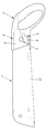
- the handle insertion part 3 comprising the saw blade 1 and the grip handle 2 and provided at the base of the saw blade 1
- the handle insertion part 3 is embedded in the grip handle 2.
- the saw blade 1 is engaged and guided by the guide member 4 to have a predetermined insertion posture, and the handle insertion portion 3 is locked to the guide member 4 by a retaining mechanism 5 provided on the grip handle 2.
- the saw blade 1 is attached to the grip handle 2 so as not to be detached, and the retaining mechanism 5 is released, the locked state of the handle insertion portion 3 to the guide member 4 is released.
- the handle insertion portion 3 is at least one of the blade portion side and the back portion side.
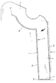
- the first slit portion 6 formed inwardly from the side edge of the handle insertion portion 3, and the first A slit portion 8 formed of a second slit portion 7 formed continuously from the rear end portion 6A of the first slit portion 6 toward the distal end side of the handle insertion portion 3 while being continuously formed in the lit portion 6.
- the slit outer portion 9 located outside the slit portion 8 of the handle insertion portion 3 receives an external force acting inward from the side edge portion side by the slit portion 8.
- the present invention relates to a replaceable blade type saw that is configured to elastically move or elastically deform inward.
- the first slit portion 6 is formed inward from a position that is a base end portion of the blade plate portion 10 of the saw blade 1 and a base end portion of the handle insertion portion 3.
- the present invention relates to a replaceable blade type saw according to claim 1.
- the second slit portion 7 is continuously formed in a side edge extending slit portion 7A formed along the side edge portion of the handle insertion portion 3 and the side edge extending slit portion 7A. And a slit 7B formed along the tip edge of the handle insertion portion 3.
- the handle insertion part 3 is formed in a trapezoidal shape in which the length of the side edge part on the blade part side is set shorter than the length of the side edge part on the back part side, and the slit part 8
- the side edge portion is formed on a blade portion side having a short side edge length, and relates to the replaceable blade type saw according to any one of claims 1 and 2.
- the handle insertion part 3 is formed in a trapezoidal shape in which the length of the side edge part on the blade part side is set shorter than the length of the side edge part on the back part side, and the slit part 8
- the side edge portion is formed on the blade portion side having a short side edge length, and relates to the replaceable blade type saw according to claim 3.
- a slit portion is formed in the handle insertion portion to impart a spring action to the handle insertion portion, and the width dimension of the handle insertion portion is larger than the width dimension of the guide member. Even so, the design insertion can be easily realized with a simple configuration in which the handle insertion portion can be inserted and engaged with the guide member by the elastic movement (or contraction elastic deformation) by the spring action. Since the slit portion formed in is not protruded from the gripping handle in a state where the saw blade is mounted on the gripping handle, the appearance appearance is not impaired, and the strength of the saw blade is also maintained.
- the handle insertion portion specifically, the slit outer portion which is the outer portion of the slit portion formed in the handle insertion portion is engaged with the guide member in a biased state by the spring action due to the formation of the slit portion.
- innovative replacement blade with excellent practicality that eliminates rattling of the handle insertion part inserted and engaged with the guide member, and ensures that the saw blade is securely mounted and fixed securely to the gripping handle. It becomes a type saw.
- the root part (base end part) of the saw blade 1 is attached to the saw handle 1 in order to attach the saw blade 1 to the grip handle 2.
- the pattern insertion part 3 during the insertion specifically, the side edge of this pattern insertion part 3, and more specifically, the pattern difference
- the outer edge portion of the slit outer portion 9 located outside the slit portion 8 formed in the insertion portion 3 abuts on the guide edge portion 4A of the guide member 4, and this handle insertion portion 3 (the outer side of the slit outer portion 9).
- the slit outer portion 9 of the handle insertion portion 3 receives a pressing action that is pressed inward from the guide member 4 (guide edge portion 4A), and slips.
- the slit outer portion 9 is elastically moved inward (shrinkage elastic deformation) by the spring action provided by the formation of the portion 8, and the handle insertion portion 3 is elastically moved inward by the slit outer portion 9.
- the handle insertion portion 3 is inserted into and engaged with the guide member 4, and the handle insertion portion 3 is inserted into and engaged with the guide member 4 by the retaining mechanism 5.
- the saw blade 1 is mounted and fixed to the grip handle 2 so that it cannot be removed from the guide member 4, and the handle insertion portion 3 is removed from the guide member 4 by the spring action of the handle insertion portion 3.
- the problem of disappearing is also eliminated, and this makes it easier to attach / detach the saw blade 1 to / from the grip 2.
- the handle insertion portion 3 inserted and engaged with the guide member 4 and positioned and fixed to the guide member 4 by the retaining mechanism 5 is returned to the slit outer portion 9 (on the guide edge portion 4A side of the guide member 4).
- the outer side of the slit 9 is pressed and engaged (biased) with the guide member 4 (guide edge 4A) due to the outward urging generated).
- the guide member of the outer side of the slit 9 4 (guide edge 4A) is pressed and the handle insertion portion 3 is positioned without rattling with respect to the guide member 4, whereby the saw blade 1 is rattled against the grip handle 2. It is mounted and fixed so that it cannot be removed without causing any problems.
- the present invention also includes a first slit portion 6 in which the slit portion 8 formed in the handle insertion portion 3 is formed inward from the side edge portion of the handle insertion portion 3, and the first slit portion 6.
- This handle is formed by the second slit portion 7 formed continuously from the rear end portion 6A of the first slit portion 6 toward the distal end side of the handle insertion portion 3 while being continuously formed in the slit portion 6.
- the slit outer portion 9 is elastically moved inward starting from the end portion 7C of the second slit portion 7 located on the distal end side of the insertion portion 3, whereby the slit is inserted into the handle insertion portion.
- the blade provided with the base end side of the handle insertion portion 3 with a shorter slit length in other words, the blade portion in the saw blade 1 Increase the amount of elastic movement (shrinkage elastic deformation) on the base end side of the plate 10
- the slit portion 8 is held by the grip handle 2 when the saw blade 1 is attached to the handle handle 2. Since it does not protrude from 2, the appearance of the appearance is not impaired, and the strength of the saw blade 1 is also maintained.
- the present embodiment is a replaceable blade type saw composed of a saw blade 1 and a grip handle 2, and a handle insertion portion provided at the root portion of the saw blade 1 (a base end portion on the side to be inserted into the grip handle 2).
- 3 is inserted into the gripping handle 2
- the handle insertion portion 3 is inserted and guided by the guide member 4 housed in the gripping handle 2, and is positioned and engaged with the guide member 4, so that the saw blade 1 is brought into a predetermined insertion posture.
- the retaining mechanism 5 provided on the gripping handle 2 prevents the handle insertion portion 3 from coming off from the guide member 4, so that the handle insertion portion 3 is locked to the guide member 4, and the saw blade 1. Is attached to the gripping handle 2 so that it cannot be detached (cannot be detached), and the retaining mechanism 5 is released to release the locked state of the handle insertion portion 3 to the guide member 4.
- the saw blade 1 can be replaced by being detached from the grip handle 2.
- the saw blade 1 specifically, the processing of the handle insertion portion 3 of the saw blade 1 and the processing of the guide member 4 into which the handle insertion portion 3 of the saw blade 1 is inserted and engaged.
- the handle insertion part 3 can be inserted into and engaged with the guide member 4.
- the slit portion 8 is formed in the handle insertion portion 3 provided at the base end portion of the saw blade 1, and the pattern difference is formed by the formation of the slit portion 8.
- the guide of the pattern insertion part 3 is caused by the spring action.
- the handle insertion part 3 is elastically moved (contracted elastically deformed) by the pressing action generated by the insertion operation (insertion operation) into the member 4,
- the width dimension of the insertion part 3 is reduced, the handle insertion part 3 can be inserted into the guide member 4 and the saw blade 1 can be attached to the gripping handle 2. Is.
- the saw blade 1 of the present embodiment is connected (integrally formed) with a blade plate portion 10 on which a blade portion is formed and a base end portion of the blade plate portion 10, and a grip handle 2 (to this grip handle 2).
- the handle insertion part 3 is inserted into and engaged with the internal guide member 4).
- the handle insertion part 3 is inserted into and fixed to the grip handle 2 (guide member 4) to be attached to the grip handle 2. It is set to be fixed.
- the length of the side edge portion on the blade portion side is shorter than the length of the side edge portion on the back portion side facing this.
- This embodiment is formed in a trapezoidal shape set to a length, and the side edge on the blade side is slightly inclined with respect to the side edge on the back side (the facing interval becomes narrower as it goes to the tip side) Is set to an inclination angle of about 3 °.) And is formed in a tapered shape that can be easily inserted into the guide member 4.
- the handle insertion portion 3 of this embodiment has a notch groove portion 11 for avoiding interference with the retaining mechanism 5 provided in the grip handle 2 when inserted into the grip handle 2 (guide member 4).
- the notch groove 11 is formed by cutting from the vicinity of the center of the distal end of the handle insertion portion 3 toward the inside (the base end side of the handle insertion portion 3) to the vicinity of the center of the plate surface of the handle insertion portion 3.
- the pattern insertion portion side insertion hole 12 through which the retaining mechanism 5 is inserted is formed in the vicinity of the center portion of the pattern insertion portion 3 that is the back of the pattern insertion portion.
- the pattern insertion portion 3 of the present embodiment is formed with the slit portion 8 for imparting a spring action to the pattern insertion portion 3, and specifically, the pattern insertion portion 3 is inserted.
- the slit portion 8 is formed only on the blade portion side of the portion 3.
- the slit portion 8 is formed continuously from the first slit portion 6 formed inward from the side edge portion of the handle insertion portion 3 and the first slit portion 6. 6, the second slit portion 7 is formed from the rear end portion 6 ⁇ / b> A toward the distal end side of the handle insertion portion 3.
- the first slit portion 6 is located near the base end portion of the handle insertion portion 3, in other words, near the boundary portion between the blade plate portion 10 constituting the saw blade 1 and the handle insertion portion 3.
- the second slit portion 7 includes a side edge extending slit portion 7A formed along the side edge portion of the handle insertion portion 3, and the side edge extending portion. It is formed of a slit portion 7B provided along the distal end edge formed along the distal end edge portion of the handle insertion portion 3 while being continuously formed in the slit portion 7A.
- the handle insertion portion 3 has an external force in which the slit outer portion 9 located outside the slit portion 8 acts inward from the side edge portion side of the handle insertion portion 3 due to the formation of the slit portion 8. It is configured to elastically move (elastically deform) inward when it receives.
- the slit portion 8, that is, both the first slit portion 6 and the second slit portion 7 are formed in a thin line shape having a width of 1 mm or less by laser processing, and the pattern is inserted. It is formed along the outer edge portion of the handle insertion portion 3 at an interval of about 5 mm with respect to the outer edge portion of the portion 3, and the handle insertion portion is further formed in the second slit portion 7.
- the end portion 7C of the leading edge extending slit portion 7B formed along the leading edge of 3 is cut inward to a position where it comes to be positioned on the leading end side with respect to the outer corner of the handle insertion portion 3. It has been configured.
- the handle insertion part 3 of the present embodiment has an external force (for example, a pressing force) acting inward from the outer side to the handle insertion part 3 by the slit part 8 formed as described above. ) Occurs, the character-shaped portion (slit outer portion 9) located outside the slit portion 8 of the handle insertion portion 3 becomes the end portion of the slit portion 8, that is, the leading edge of the second slit portion 7. It is configured to elastically rotate (shrink elastically deform) inward starting from the end portion 7C of the side-by-side slit portion 7B.
- an external force for example, a pressing force acting inward from the outer side to the handle insertion part 3 by the slit part 8 formed as described above.
- the handle insertion portion 3 on the blade side enters and moves inward to reduce the width dimension of the handle insertion portion 3 so that the width dimension of the pattern insertion portion 3 is greater than the width dimension of the guide member 4. Even if it has a large diameter, the handle insertion portion 3 can be inserted and engaged with the guide member 4. That.
- spacing dimension from the outer edge part used as the formation position of the slit part 8, what can be suitably changed with the material, thickness, shape, etc. of the pattern insertion part 3
- the present invention is not limited to those described in this embodiment.
- the grip handle 2 of the present embodiment to which the saw blade 1 is mounted is configured by abutting and connecting synthetic resin case halves, and a guide member 4 and a retaining mechanism 5 are provided therein. It is configured.
- the guide member 4 is formed in a plate shape, and is configured such that guide edge portions 4A are erected on both the left and right edge portions, and is inserted into and engaged with the guide member 4 at a substantially central portion of the plate surface.
- the guide insertion side insertion hole 13 that is in communication with the pattern insertion portion side insertion hole 12 provided in the above described pattern insertion portion 3 is provided.
- the retaining mechanism 5 is composed of a push operation portion 14, a locking pin 15, and a spring body 16.
- the locking pin 15 is inserted into the handle insertion portion 3 described above.
- a tapered insertion locking portion 15A that cannot pass through the guide member side insertion hole 12 and the guide member side insertion hole 13 of the guide member 4, and an operation portion connecting rod having a diameter smaller than the width dimension of the notch groove portion 11 of the handle insertion portion 3 15B, and when the handle insertion part 3 is inserted into and engaged with the guide member 4, the pushing operation part 14 exposed on the surface of the gripping handle 2 is pushed and operated to attach the spring body 16.
- the locking pin 15 descends and retreats against the force so that the handle insertion portion 3 can be inserted into and engaged with the guide member 4, and the handle insertion portion 3 is inserted into the guide member 4. After the engagement, when the pushing operation of the pushing operation portion 14 is released, the locking pin 15 moves back due to the urging of the spring body 16 and is inserted into the handle insertion portion side that becomes the communication hole.
- the tapered insertion locking portion 15A of the locking pin 15 is inserted into and locked into the hole 12 and the guide member side insertion hole 13, so that the handle insertion portion 3 is removed from the guide member 4 and detached. It is configured.
- the saw blade 1 When the saw blade 1 is removed from the handle 2, that is, when the insertion engagement between the handle insertion portion 3 and the guide member 4 is released, it is locked by the pushing operation of the pushing operation portion 14 as in the insertion.
- the insertion locking of the tapered insertion locking portion 15 ⁇ / b> A By retracting the pin 15, the insertion locking of the tapered insertion locking portion 15 ⁇ / b> A is released, the handle insertion portion 3 becomes free with respect to the guide member 4, and the saw blade 1 is removed from the grip handle 2. It can be removed.
- the width dimension of the handle insertion part 3 becomes larger than the width dimension of the guide member 4 due to the application of the spring action to the handle insertion part 3 by the formation of the slit part 8.
- the width dimension of the handle insertion part 3 is designed in advance to be larger than the width dimension of the guide member 4 and processed as designed. If the handle insertion portion 3 is elastically moved by the spring action of the slit portion 8 so that the handle insertion portion 3 is inserted and engaged with the guide member 4, the width dimension of the handle insertion portion 3 is caused by a processing error.
- the large diameter ratio of the handle insertion portion 3 to the guide member 4 is symptomatically. Or the handle insertion part 3 and the guide member 4 Since the width dimensions are substantially the same, it is possible to avoid as much as possible a large clearance that causes backlash between the handle insertion portion 3 and the guide member 4.
- the saw blade 1 cannot be attached to the gripping handle 2 in the conventional structure, or the saw blade 1 Even in a state where rattling occurs when the gripping handle 2 is mounted, the handle insertion portion 3 can be positioned and fixed to the guide member 4 without rattling, and the saw blade 1 can be firmly fixed without rattling. It can be attached and fixed to.
Landscapes
- Engineering & Computer Science (AREA)
- Mechanical Engineering (AREA)
- Sawing (AREA)
Priority Applications (3)
| Application Number | Priority Date | Filing Date | Title |
|---|---|---|---|
| EP17910731.3A EP3632602B1 (en) | 2017-05-24 | 2017-06-30 | Blade-replaceable saw |
| US16/316,132 US11529694B2 (en) | 2017-05-24 | 2017-06-30 | Replaceable-blade-type saw |
| CN201780041838.7A CN109414773B (zh) | 2017-05-24 | 2017-06-30 | 替刃式锯 |
Applications Claiming Priority (2)
| Application Number | Priority Date | Filing Date | Title |
|---|---|---|---|
| JP2017-102830 | 2017-05-24 | ||
| JP2017102830A JP6543655B2 (ja) | 2017-05-24 | 2017-05-24 | 替刃式鋸 |
Publications (1)
| Publication Number | Publication Date |
|---|---|
| WO2018216230A1 true WO2018216230A1 (ja) | 2018-11-29 |
Family
ID=64395502
Family Applications (1)
| Application Number | Title | Priority Date | Filing Date |
|---|---|---|---|
| PCT/JP2017/024091 Ceased WO2018216230A1 (ja) | 2017-05-24 | 2017-06-30 | 替刃式鋸 |
Country Status (5)
| Country | Link |
|---|---|
| US (1) | US11529694B2 (https=) |
| EP (1) | EP3632602B1 (https=) |
| JP (1) | JP6543655B2 (https=) |
| CN (1) | CN109414773B (https=) |
| WO (1) | WO2018216230A1 (https=) |
Families Citing this family (3)
| Publication number | Priority date | Publication date | Assignee | Title |
|---|---|---|---|---|
| US9475141B2 (en) * | 2011-08-04 | 2016-10-25 | Milwaukee Electric Tool Corporation | Reciprocating saw blade |
| GB2594914A (en) * | 2020-03-16 | 2021-11-17 | Vancebuild Ltd | A cutting apparatus |
| US11529693B2 (en) | 2020-03-17 | 2022-12-20 | Blims AS | Segmented saw |
Citations (7)
| Publication number | Priority date | Publication date | Assignee | Title |
|---|---|---|---|---|
| JPS4726192U (https=) * | 1971-04-08 | 1972-11-24 | ||
| JPS4816490U (https=) * | 1971-07-05 | 1973-02-24 | ||
| JPS6228504U (https=) * | 1985-08-06 | 1987-02-20 | ||
| JPH02117102U (https=) * | 1989-03-07 | 1990-09-19 | ||
| JP2000326303A (ja) * | 1999-05-20 | 2000-11-28 | Takagi:Kk | 刃板着脱構造 |
| JP2003062804A (ja) * | 2001-08-23 | 2003-03-05 | Kabasawa:Kk | 替刃式鋸 |
| US20100031512A1 (en) * | 2008-08-05 | 2010-02-11 | The Stanley Works | Saw blade handle with replaceable blades |
Family Cites Families (19)
| Publication number | Priority date | Publication date | Assignee | Title |
|---|---|---|---|---|
| US2140496A (en) * | 1936-05-11 | 1938-12-20 | John S Coleman | Saw construction |
| US2947085A (en) * | 1957-12-02 | 1960-08-02 | Schmitt Nicholas | Hand saw construction |
| US3946778A (en) * | 1975-02-10 | 1976-03-30 | Knuth Eugene W | Removable cutting mechanism |
| JPS6120302U (ja) | 1984-07-09 | 1986-02-05 | 増夫 渡辺 | ワンタツチ精密替刃式鋸 |
| JPH07132502A (ja) | 1993-11-11 | 1995-05-23 | Kanefusa Kk | 替刃式フィンガカッタ |
| US5722168A (en) * | 1996-07-29 | 1998-03-03 | Huang; Jung Hua | Saw blade securing mechanism |
| US6113618A (en) * | 1999-01-13 | 2000-09-05 | Stryker Corporation | Surgical saw with spring-loaded, low-noise cutting blade |
| US20040168328A1 (en) * | 2003-02-28 | 2004-09-02 | Thomas Rickey J. | Multiple orientation saw |
| CN2691761Y (zh) | 2004-02-18 | 2005-04-13 | 吉林省机械上海进出口有限公司 | 手锯 |
| US7600458B2 (en) * | 2004-04-16 | 2009-10-13 | Irwin Industrial Tool Company | Reciprocating saw blade with tapered tang stem |
| CN2714234Y (zh) * | 2004-05-14 | 2005-08-03 | 牟丹 | 一种可快速装卸的刀锯夹持机构 |
| US7325314B1 (en) * | 2005-03-15 | 2008-02-05 | King Jaws Metal Co., Ltd. | Handsaw having replaceable blade |
| SE0602684A0 (sv) * | 2006-12-11 | 2009-02-25 | Kapman Ab | Såg, handtag och blad |
| CN201026539Y (zh) * | 2006-12-30 | 2008-02-27 | 仇建平 | 一种手板锯 |
| EP2266742B1 (en) * | 2009-06-23 | 2015-04-29 | Milwaukee Electric Tool Corporation | Hand saw |
| CN103464823B (zh) * | 2013-05-07 | 2015-09-30 | 杭州巨星科技股份有限公司 | 快换手板锯 |
| CN203401153U (zh) * | 2013-06-26 | 2014-01-22 | 宁波黑松工具有限公司 | 一种往复锯的成对锯条结构 |
| CN203738150U (zh) * | 2013-12-27 | 2014-07-30 | 蒋明基 | 一种折叠式多用途手锯 |
| US9925605B2 (en) * | 2015-09-24 | 2018-03-27 | Kuang Pin Wang | Assembly of saw handle and saw member |
-
2017
- 2017-05-24 JP JP2017102830A patent/JP6543655B2/ja active Active
- 2017-06-30 EP EP17910731.3A patent/EP3632602B1/en active Active
- 2017-06-30 US US16/316,132 patent/US11529694B2/en active Active
- 2017-06-30 CN CN201780041838.7A patent/CN109414773B/zh active Active
- 2017-06-30 WO PCT/JP2017/024091 patent/WO2018216230A1/ja not_active Ceased
Patent Citations (7)
| Publication number | Priority date | Publication date | Assignee | Title |
|---|---|---|---|---|
| JPS4726192U (https=) * | 1971-04-08 | 1972-11-24 | ||
| JPS4816490U (https=) * | 1971-07-05 | 1973-02-24 | ||
| JPS6228504U (https=) * | 1985-08-06 | 1987-02-20 | ||
| JPH02117102U (https=) * | 1989-03-07 | 1990-09-19 | ||
| JP2000326303A (ja) * | 1999-05-20 | 2000-11-28 | Takagi:Kk | 刃板着脱構造 |
| JP2003062804A (ja) * | 2001-08-23 | 2003-03-05 | Kabasawa:Kk | 替刃式鋸 |
| US20100031512A1 (en) * | 2008-08-05 | 2010-02-11 | The Stanley Works | Saw blade handle with replaceable blades |
Also Published As
| Publication number | Publication date |
|---|---|
| EP3632602A1 (en) | 2020-04-08 |
| EP3632602A4 (en) | 2021-02-24 |
| US11529694B2 (en) | 2022-12-20 |
| CN109414773B (zh) | 2020-05-22 |
| US20210299770A1 (en) | 2021-09-30 |
| JP2018196958A (ja) | 2018-12-13 |
| EP3632602B1 (en) | 2023-09-20 |
| JP6543655B2 (ja) | 2019-07-10 |
| CN109414773A (zh) | 2019-03-01 |
Similar Documents
| Publication | Publication Date | Title |
|---|---|---|
| KR920001750Y1 (ko) | 카아드 코넥터 | |
| JP5027919B2 (ja) | クリップ | |
| JP6533248B2 (ja) | ブラケットの組み付け構造 | |
| WO2018216230A1 (ja) | 替刃式鋸 | |
| EP2892697A1 (en) | Safety razor | |
| JP2018196958A5 (https=) | ||
| EP1922946B1 (en) | Sheet attaching instrument | |
| JP7141376B2 (ja) | バケット用のツース取付構造、及びバケット用のツース | |
| JP2011503454A (ja) | 支持部材に取付部材を固定するための固定具、並びに該固定具を備えた固定装置 | |
| CN117325217A (zh) | 实用刀片和组合刀片夹 | |
| EP2899038A1 (en) | Rotary operated writing instrument | |
| JP2023034650A (ja) | バンドおよび時計 | |
| JP4278347B2 (ja) | 係止部品脚部の取付構造 | |
| JP6565617B2 (ja) | シフトノブ構造 | |
| JP5233008B2 (ja) | カッターナイフ | |
| JP5256904B2 (ja) | トリガスイッチ | |
| JP5636564B2 (ja) | カッターナイフ | |
| JP4649903B2 (ja) | 摺動式クリップナット | |
| US8959737B2 (en) | Fixture means | |
| JP2008291993A (ja) | クリップによる取付け構造 | |
| JP2020023846A (ja) | 車両のドアハンドル | |
| JP5259314B2 (ja) | 筆記具のクリップ取付構造 | |
| JPH0444391Y2 (https=) | ||
| JP6490987B2 (ja) | スライドノック式筆記具 | |
| JP2000141989A (ja) | 長尺物繰り出し装置 |
Legal Events
| Date | Code | Title | Description |
|---|---|---|---|
| 121 | Ep: the epo has been informed by wipo that ep was designated in this application |
Ref document number: 17910731 Country of ref document: EP Kind code of ref document: A1 |
|
| NENP | Non-entry into the national phase |
Ref country code: DE |
|
| WWE | Wipo information: entry into national phase |
Ref document number: 2017910731 Country of ref document: EP |
|
| ENP | Entry into the national phase |
Ref document number: 2017910731 Country of ref document: EP Effective date: 20200102 |