WO2018207607A1 - 電源装置及びこれを備える車両、蓄電装置並びに電源装置用セパレータ - Google Patents
電源装置及びこれを備える車両、蓄電装置並びに電源装置用セパレータ Download PDFInfo
- Publication number
- WO2018207607A1 WO2018207607A1 PCT/JP2018/016510 JP2018016510W WO2018207607A1 WO 2018207607 A1 WO2018207607 A1 WO 2018207607A1 JP 2018016510 W JP2018016510 W JP 2018016510W WO 2018207607 A1 WO2018207607 A1 WO 2018207607A1
- Authority
- WO
- WIPO (PCT)
- Prior art keywords
- power supply
- supply device
- separator
- hole
- secondary battery
- Prior art date
- Legal status (The legal status is an assumption and is not a legal conclusion. Google has not performed a legal analysis and makes no representation as to the accuracy of the status listed.)
- Ceased
Links
Images


Classifications
-
- H—ELECTRICITY
- H01—ELECTRIC ELEMENTS
- H01M—PROCESSES OR MEANS, e.g. BATTERIES, FOR THE DIRECT CONVERSION OF CHEMICAL ENERGY INTO ELECTRICAL ENERGY
- H01M10/00—Secondary cells; Manufacture thereof
- H01M10/60—Heating or cooling; Temperature control
- H01M10/62—Heating or cooling; Temperature control specially adapted for specific applications
- H01M10/625—Vehicles
-
- H—ELECTRICITY
- H01—ELECTRIC ELEMENTS
- H01M—PROCESSES OR MEANS, e.g. BATTERIES, FOR THE DIRECT CONVERSION OF CHEMICAL ENERGY INTO ELECTRICAL ENERGY
- H01M10/00—Secondary cells; Manufacture thereof
- H01M10/42—Methods or arrangements for servicing or maintenance of secondary cells or secondary half-cells
- H01M10/44—Methods for charging or discharging
-
- H—ELECTRICITY
- H01—ELECTRIC ELEMENTS
- H01M—PROCESSES OR MEANS, e.g. BATTERIES, FOR THE DIRECT CONVERSION OF CHEMICAL ENERGY INTO ELECTRICAL ENERGY
- H01M10/00—Secondary cells; Manufacture thereof
- H01M10/60—Heating or cooling; Temperature control
- H01M10/62—Heating or cooling; Temperature control specially adapted for specific applications
- H01M10/627—Stationary installations, e.g. power plant buffering or backup power supplies
-
- H—ELECTRICITY
- H01—ELECTRIC ELEMENTS
- H01M—PROCESSES OR MEANS, e.g. BATTERIES, FOR THE DIRECT CONVERSION OF CHEMICAL ENERGY INTO ELECTRICAL ENERGY
- H01M10/00—Secondary cells; Manufacture thereof
- H01M10/60—Heating or cooling; Temperature control
- H01M10/64—Heating or cooling; Temperature control characterised by the shape of the cells
- H01M10/647—Prismatic or flat cells, e.g. pouch cells
-
- H—ELECTRICITY
- H01—ELECTRIC ELEMENTS
- H01M—PROCESSES OR MEANS, e.g. BATTERIES, FOR THE DIRECT CONVERSION OF CHEMICAL ENERGY INTO ELECTRICAL ENERGY
- H01M10/00—Secondary cells; Manufacture thereof
- H01M10/60—Heating or cooling; Temperature control
- H01M10/65—Means for temperature control structurally associated with the cells
- H01M10/651—Means for temperature control structurally associated with the cells characterised by parameters specified by a numeric value or mathematical formula, e.g. ratios, sizes or concentrations
- H01M10/652—Means for temperature control structurally associated with the cells characterised by parameters specified by a numeric value or mathematical formula, e.g. ratios, sizes or concentrations characterised by gradients
-
- H—ELECTRICITY
- H01—ELECTRIC ELEMENTS
- H01M—PROCESSES OR MEANS, e.g. BATTERIES, FOR THE DIRECT CONVERSION OF CHEMICAL ENERGY INTO ELECTRICAL ENERGY
- H01M10/00—Secondary cells; Manufacture thereof
- H01M10/60—Heating or cooling; Temperature control
- H01M10/65—Means for temperature control structurally associated with the cells
- H01M10/655—Solid structures for heat exchange or heat conduction
- H01M10/6556—Solid parts with flow channel passages or pipes for heat exchange
- H01M10/6557—Solid parts with flow channel passages or pipes for heat exchange arranged between the cells
-
- H—ELECTRICITY
- H01—ELECTRIC ELEMENTS
- H01M—PROCESSES OR MEANS, e.g. BATTERIES, FOR THE DIRECT CONVERSION OF CHEMICAL ENERGY INTO ELECTRICAL ENERGY
- H01M10/00—Secondary cells; Manufacture thereof
- H01M10/60—Heating or cooling; Temperature control
- H01M10/65—Means for temperature control structurally associated with the cells
- H01M10/656—Means for temperature control structurally associated with the cells characterised by the type of heat-exchange fluid
- H01M10/6561—Gases
-
- H—ELECTRICITY
- H01—ELECTRIC ELEMENTS
- H01M—PROCESSES OR MEANS, e.g. BATTERIES, FOR THE DIRECT CONVERSION OF CHEMICAL ENERGY INTO ELECTRICAL ENERGY
- H01M10/00—Secondary cells; Manufacture thereof
- H01M10/60—Heating or cooling; Temperature control
- H01M10/65—Means for temperature control structurally associated with the cells
- H01M10/658—Means for temperature control structurally associated with the cells by thermal insulation or shielding
-
- H—ELECTRICITY
- H01—ELECTRIC ELEMENTS
- H01M—PROCESSES OR MEANS, e.g. BATTERIES, FOR THE DIRECT CONVERSION OF CHEMICAL ENERGY INTO ELECTRICAL ENERGY
- H01M50/00—Constructional details or processes of manufacture of the non-active parts of electrochemical cells other than fuel cells, e.g. hybrid cells
- H01M50/20—Mountings; Secondary casings or frames; Racks, modules or packs; Suspension devices; Shock absorbers; Transport or carrying devices; Holders
- H01M50/204—Racks, modules or packs for multiple batteries or multiple cells
- H01M50/207—Racks, modules or packs for multiple batteries or multiple cells characterised by their shape
- H01M50/209—Racks, modules or packs for multiple batteries or multiple cells characterised by their shape adapted for prismatic or rectangular cells
-
- Y—GENERAL TAGGING OF NEW TECHNOLOGICAL DEVELOPMENTS; GENERAL TAGGING OF CROSS-SECTIONAL TECHNOLOGIES SPANNING OVER SEVERAL SECTIONS OF THE IPC; TECHNICAL SUBJECTS COVERED BY FORMER USPC CROSS-REFERENCE ART COLLECTIONS [XRACs] AND DIGESTS
- Y02—TECHNOLOGIES OR APPLICATIONS FOR MITIGATION OR ADAPTATION AGAINST CLIMATE CHANGE
- Y02E—REDUCTION OF GREENHOUSE GAS [GHG] EMISSIONS, RELATED TO ENERGY GENERATION, TRANSMISSION OR DISTRIBUTION
- Y02E60/00—Enabling technologies; Technologies with a potential or indirect contribution to GHG emissions mitigation
- Y02E60/10—Energy storage using batteries
Definitions
- the present invention relates to a power supply device, a vehicle including the same, a power storage device, and a power supply device separator.
- a power supply device in which a large number of secondary batteries are connected in series and in parallel is used for purposes such as driving a vehicle.
- An example of such a power supply device is shown in the exploded perspective view of FIG.
- a large number of rectangular secondary battery cells 901 are stacked via spacers 902, an end plate 903 is disposed on an end surface, and fastened by a bind bar 904.
- the spacer 902 is insulative and is made of hard resin or the like.
- the spacers arranged between the secondary battery cells are also required to be downsized.
- the present invention has been made in view of such a background.
- One of the objects of the present invention is to provide a power supply device having an anti-burning function for reducing the influence on other secondary battery cells adjacent when a part of the secondary battery cells becomes high temperature, and a vehicle including the power supply device,
- An object of the present invention is to provide a power storage device and a separator for a power supply device.
- the power supply device includes a plurality of secondary battery cells arranged adjacent to each other and separators interposed between the adjacent secondary battery cells, respectively.
- each separator can be formed with a plurality of holes having a predetermined size on the surface thereof and having an opening edge as a closed space.
- the hole portion can be a through hole.
- the hole can be easily formed.
- the hole portion can be formed to be inclined with respect to the separator surface.
- the hole can be a non-through hole.
- the hole is opened on the first main surface side of the separator and on the side opposite to the first main surface.
- the second main surface can be opened at a position different from the position of the hole opened in the first main surface.
- the diameter of the hole portion can be formed to 5 mm or less. Therefore, generation
- each separator includes a first layer in which the hole is formed, and a second layer having a heat resistance different from that of the first layer. Layers can be stacked. Thereby, a different characteristic for every layer can be added and the function of a separator can be improved.
- the second layer can be made thicker than the first layer.
- the hole portion may be formed in a part of the separator.
- a power supply device for driving the vehicle in addition to any of the above-described configurations, a power supply device for driving the vehicle can be provided.
- the power supply device according to any one of the above configurations, the traveling motor supplied with power from the power supply device, the power supply device, and the motor.
- the vehicle main body mounted and the wheel which drives with the said motor and drives the said vehicle main body can be provided.
- the power storage device includes the power supply device according to any one of the above-described configurations and a power supply controller that controls charge / discharge of the power supply device.
- the secondary battery cell can be charged with the electric power from the secondary battery and the secondary battery cell can be controlled to be charged.
- the separator according to the thirteenth embodiment is a separator for interposing between a plurality of secondary battery cells arranged adjacent to each other, and is composed of a hard member having insulation properties.
- a plurality of holes having a predetermined size and having an opening edge as a closed space can be formed in a predetermined pattern on the surface.
- FIG. 4A is a cross-sectional view of the separator according to Embodiment 1
- FIG. 4B is a cross-sectional view of the separator according to Embodiment 2
- FIG. 4C is a cross-sectional view of the separator according to Embodiment 3
- FIG. 4D is a cross-section of the separator according to Embodiment 4.
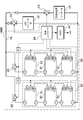
- FIG. It is a block diagram which shows the example which mounts a battery apparatus in the hybrid vehicle which drive
- each element constituting the present invention may be configured such that a plurality of elements are constituted by the same member and the plurality of elements are shared by one member, and conversely, the function of one member is constituted by a plurality of members. It can also be realized by sharing.
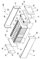
- FIG. 1 is a perspective view of a power supply device 100 according to Embodiment 1 of the present invention
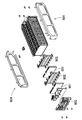
- FIG. 2 is an exploded perspective view thereof.
- a power supply device 100 shown in these drawings includes a battery stack 2 in which a plurality of secondary battery cells 1 are stacked, a pair of end plates 3 disposed at both ends of the battery stack 2, and a pair of end plates. 3 is provided with a pair of fastening members 4 that are connected to both ends and fasten the battery stack 2. Further, in the power supply device 100, the fastening member 4 is bent at both ends of the main body 40 disposed along the side surface of the battery stack 2 and fixed to the outer surface of the end plate 3. The fixing part 41 is provided.
- the secondary battery cell 1 is a prismatic battery that is wider than the thickness, in other words, is thinner than the width, and is stacked in the thickness direction to form a battery stack 2.
- the secondary battery cell 1 is a lithium ion secondary battery.
- the secondary battery cell may be any rechargeable secondary battery such as a nickel metal hydride battery or a nickel cadmium battery.
- the secondary battery cell 1 accommodates positive and negative electrode plates together with an electrolyte in a sealed outer can.
- the outer can is formed by press-molding a metal plate such as aluminum or aluminum alloy into a square shape, and the opening is hermetically sealed with a sealing plate.
- the sealing plate is made of the same aluminum or aluminum alloy as the outer can, and the positive and negative electrode terminals 11 are fixed to both ends. Further, the sealing plate is provided with a gas discharge valve 15 between the positive and negative electrode terminals 11.
- the plurality of secondary battery cells 1 are stacked such that the thickness direction of each secondary battery cell 1 is the stacking direction to form a battery stack 2.
- a terminal surface 10 provided with positive and negative electrode terminals 11 is arranged on the same plane, and a plurality of secondary battery cells 1 are stacked to form a battery stack 2.
- the battery stack 2 has separators 12 sandwiched between the secondary battery cells 1 being stacked.
- the separator 12 shown in the figure is made of an insulating material in a thin plate shape or sheet shape.
- the separator 12 shown in the figure has a plate shape having a size substantially equal to the opposing surface of the secondary battery cell 1, and the separator 12 is stacked between the adjacent secondary battery cells 1 to thereby adjoin the secondary battery.
- the cells 1 are insulated from each other.
- the separator 12 may have a shape in which a cooling gas flow path is formed between the secondary battery cell 1 and the spacer.
- the surface of the secondary battery cell 1 can also be coat
- Battery stack 2 In the battery stack 2, a metal bus bar (not shown) is connected to the positive and negative electrode terminals 11 of adjacent secondary battery cells 1, and a plurality of secondary battery cells 1 are connected in series or in parallel with the bus bar. Alternatively, they are connected in series and in parallel.
- the battery stack 2 shown in the figure has twelve secondary battery cells 1 connected in series. However, the present invention does not specify the number of secondary battery cells 1 constituting the battery stack and the connection state thereof.
- End face spacer 13 In the battery stack 2, end plates 3 are arranged with end face spacers 13 sandwiched between both end faces. As shown in FIG. 2, the end surface spacer 13 is disposed between the battery stack 2 and the end plate 3 to insulate the end plate 3 from the battery stack 2.
- the end face spacer 13 can be made of the same material as the separator 12 described above.
- the end surface spacer 13 shown in the drawing includes a plate portion 13X having a size capable of covering the entire facing surface of the secondary battery cell 1, and the secondary battery cell in which the plate portion 13X is disposed at both ends of the battery stack 2. 1 and the end plate 3 are stacked.
- the end surface spacer 13 of FIG. 2 is provided with a terminal surface cover portion 13A that covers the terminal surface 10 of the secondary battery cell 1 connected to the upper end edge of the plate portion 13X.
- the end surface spacer 13 of FIG. 2 is provided with a terminal surface cover portion 13A that protrudes toward the secondary battery cell 1 over the entire upper end edge of the plate portion 13X.
- the structure in which the terminal surface cover portion 13A is provided over the entire upper end edge of the plate portion 13X has a terminal which is the upper surface of the secondary battery cell 1 while ensuring an insulation distance between the end plate 3 and the battery stack 2.
- the insulating property can be improved by reliably covering the surface 10.
- End plate 3 As shown in FIGS. 1 and 2, the end plate 3 is disposed at both ends of the battery stack 2 and is fastened via fastening members 4 disposed along both side surfaces of the battery stack 2.
- the end plates 3 are arranged at both ends of the battery stack 2 in the stacking direction of the secondary battery cells 1 and outside the end face spacer 13 to sandwich the battery stack 2 from both ends.
- the end plate 3 is made of an aluminum alloy.
- Aluminum alloys include Al-Cu-Mg, Al-Cu-Ni-Mg, Al-Cu-Si, Al-Si-Mg, Al-Si-Cu, Al-Si-Cu-Mg Al-Si-Cu-Ni-Mg system can be used.
- the end plate 3 made of aluminum alloy is a heat treatment type alloy.
- the end plate 3 made of aluminum alloy is molded by die casting as will be described later. Moreover, it is preferable that the end plate 3 made of an aluminum alloy is tempered by heat treatment including solution treatment, quenching, aging heat treatment, and the like, as will be described later.
- the end plate 3 has a quadrangular outer shape and is disposed so as to face the end surface of the battery stack 2.
- the end plate 3 shown in FIGS. 1 and 2 has an outer shape substantially equal to the outer shape of the secondary battery cell 1.
- the end plate 3 shown in the drawing has a horizontal width equal to the width of the secondary battery cell 1 and a vertical height equal to the height of the secondary battery cell 1.
- the vertical direction is the vertical direction in the figure
- the horizontal direction is the horizontal direction in the figure and means a horizontal direction perpendicular to the stacking direction of the batteries.
- the end plate 3 shown in FIG. 2 has a plurality of through holes for fixing the end plate 3.
- the end plate 3 has a first through hole 33 for inserting the fastener 19 for fixing the fixing portion 41 of the fastening member 4.
- the end plate 3 shown in the figure has a plurality of through holes as the first through holes 33.
- the end plate 3 shown in the drawing is provided with a plurality of first through holes 33 that are spaced apart from each other at positions opposite to the fixed portion 41 on both sides.
- the end plate 3 in FIG. 2 is provided with six first through holes 33 in total, three along each side.
- the fastener 19 that penetrates the fixing portion 41 disposed on the outer peripheral surface is inserted into the first through hole 33.
- the fastener 19 inserted into the first through hole 33 is fixed to the first through hole 33 to fix the fixing portion 41 at a fixed position.
- the end plate 3 has a second through hole 34 different from the first through hole 33 and has a through hole for inserting a bolt for fixing the power supply device to a fixing portion (for example, a vehicle in a vehicle-mounted power supply device). Forming.
- the second through holes 34 are penetrated as vertical holes at both ends on the upper surface of the end plate 3.
- the fastener 19 is fixed to the first through hole 33 so as not to come off.
- a set screw, a bolt, a rivet or the like can be used.
- the fastener is screwed into the first through hole 33 and fixed. Therefore, the first through-hole 33 to which the fastener, which is a set screw or a bolt, is fixed can be provided with a female screw that meshes with the set screw or the male screw of the bolt on the inner surface.
- the fastener that is a rivet is inserted into the first through hole 33 of the end plate 3 in a state of passing through the fixing portion, and one end thereof is caulked inside the first through hole 33 to thereby fix the end plate 3 and the fixing portion. And fix.
- the fastener, which is a rivet sandwiches the first through hole 33 of the end plate 3 and the opening edge of the through hole of the fixed portion by a caulking portion formed inside the first through hole 33 of the end plate 3. Then, the fixing portion is fixed to the end plate 3.
- the first through-hole 33 into which the rivet is inserted has an inner shape in which the opening area of the outer surface is reduced so that it cannot pass through the head of the rivet, and the opening area on the opposite surface side, which is the opposite side, is increased. It can be set as the structure which can arrange
- the fastening member 4 is extended in the stacking direction of the battery stack 2, and both ends are fixed to end plates 3 arranged on both end faces of the battery stack 2,
- the battery stack 2 is fastened in the stacking direction via the end plate 3.
- the fastening member 4 is a metal plate having a predetermined width and a predetermined thickness along the side surface of the battery stack 2, and is disposed to face both side surfaces of the battery stack 2.
- the fastening member 4 can be a metal plate such as iron, preferably a steel plate.
- the fastening member 4 made of a metal plate is bent into a predetermined shape by press molding or the like.
- the fastening member 4 includes a main body portion 40 arranged along the side surface of the battery stack 2, and a fixing portion 41 that is bent at both ends of the main body portion 40 and fixed to the outer surface of the end plate 3. ing.
- the main body 40 has a rectangular shape with a size that covers almost the entire battery stack 2 and the end plates 3 disposed at both ends thereof.
- the main body 40 shown in FIG. 1 covers almost the entire side surface of the battery stack 2 without any gaps.
- the main body 40 can also be provided with one or more openings to expose part of the side surface of the battery stack.
- the fastening member 4 is provided with a fixing portion 41 by bending both end portions along the outer surface of the end plate 3.
- the fixing portion 41 shown in the figure is substantially equal to the height of the main body portion 40 and the end plate 3 in the vertical direction and covers the left and right side portions of the end plate 3.
- the fastening member 4 is fixed to the end plate 3 via a fastener 19 inserted in a through hole 42 provided at the tip of the fixing portion 41.
- the fastening member 4 shown in the drawing includes a bent portion 44 that holds the upper surface and the lower surface of the battery stack 2 along the upper end portion of the intermediate portion excluding both end portions of the main body portion 40.
- the bent portion 44 holds the upper and lower surfaces of the secondary battery cells 1 constituting the battery stack 2 and suppresses the position of the terminal surface 10 of each secondary battery cell 1 from shifting up and down.
- the fastening member 4 is not shown in figure, an insulating sheet is arrange
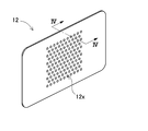
- FIG. 12 A perspective view of the separator 12 is shown in FIG.
- the separator 12 is composed of a hard member having insulating properties.
- a large number of holes 12x are opened on the surface of the separator 12.
- the hole 12x is opened to a predetermined size.
- the hole 12x has an opening edge as a closed space.
- each hole 12x is formed individually, and the holes 12x are not communicated with each other.
- the hole 12x is formed in a predetermined pattern.
- the holes 12x are arranged offset for each adjacent row.
- positions a hole part can also be made into the grid shape, concentric form, spiral shape, or random.
- the surface area of the separator 12 is preferably smaller than the surface of the secondary battery cell. Thereby, when the secondary battery cell expands, the force applied to the sealing body of the secondary battery cell can be reduced, and damage to the outer can of the secondary battery cell can be avoided. Further, by making the separator 12 one size smaller than the secondary battery cell, the effect of reducing the heat transfer area and improving the heat insulation can be obtained.
- the hole portion can be formed not only uniformly on the entire surface of the separator but also partially.
- a hole is formed in the central portion of the main surface of the separator 12.
- the central portion of the outer can of the secondary battery cell expands, and this portion in particular presses the separator and heat is easily transmitted. Therefore, by forming many holes in the central portion, the heat insulation performance of the central portion of the separator can be enhanced by air insulation. Further, when a large number of holes are formed, it is expected that the flexibility of the separator is partially improved and the effect of absorbing deformation is also exhibited.
- the shape of the hole 12x may be a circular shape, or may be a polygonal shape such as an elliptical shape, a rectangular shape, or a hexagonal shape. Further, it may be a through hole or a non-through hole. Moreover, it is not necessary for each hole 12 to have the same shape, and a plurality of types of shapes can be combined. Many holes can be formed, for example, by punching the surface of the separator.
- the diameter of the hole 12x is preferably small so as not to cause thermal convection, for example, 5 mm or less.
- the hole may be formed obliquely.
- the separator 12A As the separator 12A according to the first embodiment, an example of a hole 12a that is penetrated in an oblique direction in a cross-sectional view is shown in the cross-sectional view of FIG. 4A.
- the path of the hole 12a is lengthened compared to the case where the hole is formed perpendicular to the separator surface, Thermal resistance can be increased.
- the hole when the hole is a non-through hole, it can be formed on only one main surface of the separator and on both surfaces. At this time, it is preferable that the holes formed on each surface are formed at positions that do not overlap.
- FIG. 4B Such an example is shown in the sectional view of FIG. 4B as the separator 12B according to the second embodiment.
- the separator 12B shown in this figure has a hole 12b1 opened in the first main surface side 12B1 (right side in the drawing) of the separator 12B, and the second main surface 12B2 opposite to the first main surface 12B1
- the hole 12b2 is opened at a position different from the position of the hole 12b1 opened in the main surface 12B1.
- the separator 12C is formed of a porous material, and heat insulation is exhibited by a large number of porous 12c contained in the separator 12C, that is, gas such as air contained in bubbles.
- the fire spread prevention layer is formed. If it is this structure, a process is easy and can show the heat insulation performance comparatively easily.
- the porous separator 12C functions as a fire spread prevention layer by enhancing heat insulation.
- the fire spread prevention layer preferably functions as the entire separator 12C by uniformly dispersing the porous 12c in the cross section of the separator 12C.
- the porous layer may be unevenly distributed only on the surface of the separator. In this case, only a part of the separator provided with the porous layer functions as a fire spread prevention layer.
- the presence of the porous layer inside the separator 12C contributes to the ease of deformation.
- the separator is made of a heat insulating material.
- the separator 12C in FIG. 4C is configured by filling a solid resin with bubbles.
- the resin material an organic material such as a foamable polyurethane resin, a hybrid resin of an organic material and an inorganic material, or the like can be used.
- the thermally weak portion can be protected and a glass transition point can be avoided.
- the separator may be formed of a plurality of layers.
- a heat insulating layer 12D1 having a hole and an insulating layer 12D2 having different heat resistance from the heat insulating layer 12D1 are stacked.
- the separator 12D has a structure in which the heat insulating layer 12D1 and the insulating layer 12D2 are laminated, the heat insulating layer 12D1 itself does not have to be insulative, and the degree of freedom in material selection is improved.
- the rigidity of the separator can be increased on the insulating layer side.
- the rigidity can be further increased.
- the positions of the through holes on the insulating layer side are different from the positions of the through holes on the heat insulating layer side, so that these holes are stacked and non-through holes do not overlap Can be easily formed.
- the heat insulating layer and the insulating layer may be made of different materials.
- the heat insulating layer is formed of a highly heat-insulating material, and the insulating layer is formed of a material having flexibility, whereby heat insulating properties and flexibility can be added to the separator.
- the number of stacked layers is not limited to two, but may be three or more. In this case, different functions may be added. For example, through holes are formed in the heat insulating layer to exhibit heat insulating properties, the intermediate insulating layer is a solid layer to improve the strength, and the third layer is a flexible layer to make the separator flexible. In addition, when the secondary battery cell is thermally expanded, the deformation can be absorbed.
- the vibration resistance and impact resistance of the battery module can be improved.
- a non-slip coating is applied to the separator surface.
- the outer can is applied to a secondary battery cell having a square shape.
- the present invention is not limited to this, and batteries of other shapes, for example, a laminated secondary battery cell or a cylindrical battery can be used. It can also be applied to secondary battery cells.
- the above power supply devices can be used as in-vehicle power supplies.
- a vehicle equipped with a power supply device an electric vehicle such as a hybrid vehicle or a plug-in hybrid vehicle that runs with both an engine and a motor, or an electric vehicle that runs only with a motor can be used, and it is used as a power source for these vehicles.
- a description will be given of an example in which a large-capacity, high-output power supply device 1000 in which a large number of the above-described power supply devices are connected in series or in parallel and a necessary control circuit is added is constructed. .
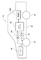
- FIG. 5 shows an example in which a power supply device is mounted on a hybrid vehicle that travels with both an engine and a motor.
- a vehicle HV equipped with the power supply device shown in this figure includes a vehicle main body 90, an engine 96 and a travel motor 93 that travel the vehicle main body 90, a power supply device 1000 that supplies power to the motor 93, A generator 94 that charges the battery, and a wheel 97 that is driven by a motor 93 and an engine 96 to run the vehicle main body 90 are provided.
- the power supply apparatus 1000 is connected to a motor 93 and a generator 94 via a DC / AC inverter 95.
- the vehicle HV travels by both the motor 93 and the engine 96 while charging / discharging the battery of the power supply apparatus 1000.
- the motor 93 is driven to drive the vehicle when the engine efficiency is low, for example, during acceleration or low-speed driving.
- the motor 93 is driven by power supplied from the power supply apparatus 1000.
- the generator 94 is driven by the engine 96, or is driven by regenerative braking when the vehicle is braked, and charges the battery of the power supply apparatus 1000.
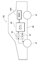
- FIG. 6 shows an example in which a power supply device is mounted on an electric vehicle that runs only with a motor.
- a vehicle EV equipped with the power supply device shown in this figure includes a vehicle main body 90, a motor 93 for running the vehicle main body 90, a power supply device 1000 that supplies power to the motor 93, and a battery of the power supply device 1000. And a wheel 97 that is driven by a motor 93 and travels the vehicle main body 90.
- the motor 93 is driven by power supplied from the power supply apparatus 1000.
- the generator 94 is driven by energy when regeneratively braking the vehicle EV and charges the battery of the power supply apparatus 1000.
- this power supply apparatus can be used not only as a power source for a moving body but also as a stationary power storage facility.
- a power source for home and factory use a power supply system that is charged with sunlight or midnight power and discharged when necessary, or a streetlight power supply that charges sunlight during the day and discharges at night, or during a power outage It can also be used as a backup power source for driving signals.
- FIG. The power supply apparatus 1000 shown in this figure forms a battery unit 82 by connecting a plurality of battery packs 81 in a unit shape. Each battery pack 81 has a plurality of secondary battery cells connected in series and / or in parallel.
- Each battery pack 81 is controlled by a power controller 84.
- the power supply apparatus 1000 drives the load LD after charging the battery unit 82 with the charging power supply CP. Therefore, the power supply apparatus 1000 has a charge mode and a discharge mode.
- the load LD and the charging power source CP are connected to the power supply apparatus 1000 via the discharging switch DS and the charging switch CS, respectively.
- ON / OFF of the discharge switch DS and the charge switch CS is switched by the power supply controller 84 of the power supply apparatus 1000.
- the power controller 84 switches the charging switch CS to ON and the discharging switch DS to OFF to permit charging from the charging power supply CP to the power supply apparatus 1000.
- the power controller 84 turns off the charging switch CS and turns on the discharging switch DS to discharge.
- the mode is switched to permit discharge from the power supply apparatus 1000 to the load LD.
- the charge switch CS can be turned on and the discharge switch DS can be turned on to supply power to the load LD and charge the power supply apparatus 1000 at the same time.
- the load LD driven by the power supply apparatus 1000 is connected to the power supply apparatus 1000 via the discharge switch DS.
- the power supply controller 84 switches the discharge switch DS to ON, connects to the load LD, and drives the load LD with the power from the power supply apparatus 1000.
- the discharge switch DS a switching element such as an FET can be used. ON / OFF of the discharge switch DS is controlled by the power supply controller 84 of the power supply apparatus 1000.
- the power controller 84 also includes a communication interface for communicating with external devices. In the example of FIG. 7, it is connected to the host device HT according to an existing communication protocol such as UART or RS-232C. Further, if necessary, a user interface for the user to operate the power supply system can be provided.
- Each battery pack 81 includes a signal terminal and a power supply terminal.
- the signal terminals include a pack input / output terminal DI, a pack abnormality output terminal DA, and a pack connection terminal DO.
- the pack input / output terminal DI is a terminal for inputting / outputting signals from other pack batteries and the power supply controller 84
- the pack connection terminal DO is for inputting / outputting signals to / from other pack batteries which are child packs.
- the pack abnormality output terminal DA is a terminal for outputting the abnormality of the battery pack to the outside.
- the power supply terminal is a terminal for connecting the battery packs 81 in series and in parallel.
- the battery units 82 are connected to the output line OL via the parallel connection switch 85 and connected in parallel to each other.
- a power supply device for a power source of a plug-in hybrid electric vehicle, a hybrid electric vehicle, an electric vehicle, or the like that can switch between an EV traveling mode and an HEV traveling mode It can be suitably used as a device.
- a backup power supply device that can be mounted on a rack of a computer server, a backup power supply device for a wireless base station such as a mobile phone, a power storage device for home use and a factory, a power supply for a street light, etc. Also, it can be used as appropriate for applications such as a backup power source such as a traffic light.
Landscapes
- Manufacturing & Machinery (AREA)
- Chemical & Material Sciences (AREA)
- Chemical Kinetics & Catalysis (AREA)
- Electrochemistry (AREA)
- General Chemical & Material Sciences (AREA)
- Engineering & Computer Science (AREA)
- Secondary Cells (AREA)
- Physics & Mathematics (AREA)
- General Physics & Mathematics (AREA)
- Mathematical Analysis (AREA)
- Mathematical Optimization (AREA)
- Pure & Applied Mathematics (AREA)
- Algebra (AREA)
- Battery Mounting, Suspending (AREA)
Abstract
二次電池セルの一部が高温となった際に隣接する他の二次電池セルに与える影響を低減させる類焼防止機能をセパレータに設けるために、電源装置(100)は、互いに隣接して配置された複数の二次電池セル(1)と、前記隣接する二次電池セル(1)同士の間に、それぞれ介在されるセパレータ(12)とを備える。各セパレータ(12)は、その表面に、所定のパターンで形成される複数の穴部を有している。穴部は、所定の大きさに開口し、開口端縁を閉空間としている。
Description
本発明は、電源装置及びこれを備える車両、蓄電装置並びに電源装置用セパレータに関する。
多数の二次電池を直列、並列に接続した電源装置は、車両の駆動用等の用途で用いられている。このような電源装置の一例を図8の分解斜視図に示す。この図に示す電源装置は、角形の二次電池セル901をスペーサ902を介して多数積層して、端面にエンドプレート903を配置し、バインドバー904で締結している。スペーサ902は絶縁性で、硬質の樹脂等で構成されている。
近年の電池に対する高出力、かつ小型化の要求に伴い、二次電池セルの高容量化が進められている一方、複数の二次電池セルを組み合わせた電池モジュールに対する安全性の確保が重要な課題となっている。特に、一の二次電池セルが高温になった際、隣接する他の二次電池セルに熱が伝搬するいわゆる類焼試験における対策技術の確立が急務となっている。類焼試験とは、電池モジュールに含まれる二次電池セルの1つが熱暴走したときに、周囲の二次電池セルに熱連鎖していき、最終的に電池モジュールが破裂又は発火することがないかを検証する試験である。
さらにまた、二次電池セル間に配置されるスペーサについても小型化が求められている。
本発明は、このような背景に鑑みてなされたものである。本発明の目的の一は、二次電池セルの一部が高温となった際に隣接する他の二次電池セルに与える影響を低減させる類焼防止機能を備えた電源装置及びこれを備える車両、蓄電装置並びに電源装置用セパレータを提供することにある。
本発明の第1の形態に係る電源装置によれば、互いに隣接して配置された複数の二次電池セルと、前記隣接する二次電池セル同士の間に、それぞれ介在されるセパレータとを備える電源装置であって、各セパレータは、その表面に、所定の大きさに開口し、開口端縁を閉空間とした穴部を、所定のパターンで複数形成することができる。上記構成により、多数の穴部を空気層として、セパレータの断熱性を高め、隣接する二次電池セル間を断熱して類焼や延焼を効果的に阻止できる。
また、第2の形態に係る電源装置によれば、上記構成に加えて、前記穴部を貫通孔とできる。上記構成により、穴部を容易に形成できる。
さらに、第3の形態に係る電源装置によれば、上記何れかの構成に加えて、前記穴部を、前記セパレータ表面に対して傾斜して形成することができる。上記構成により、穴部をセパレータ表面に対して垂直に形成した場合と比べ、穴部の経路を長くして、熱抵抗を大きくすることができる。
さらにまた、第4の形態に係る電源装置によれば、上記何れかの構成に加えて、前記穴部を非貫通孔とできる。上記構成により、熱の対流移動を阻止して断熱性能を高めることができる。
さらにまた、第5の形態に係る電源装置によれば、上記何れかの構成に加えて、前記穴部を、前記セパレータの第一主面側に開口させると共に、前記第一主面と反対側の第二主面において、前記第一主面に開口された穴部の位置とは異なる位置に開口させることができる。上記構成により、穴部を非貫通孔としつつ、セパレータの両面に、重複しない位置に開口させることで、穴部の深さを貫通孔と比べて浅くしながら、実質的に穴部の体積を増して断熱性能を高めることができる。
さらにまた、第6の形態に係る電源装置によれば、上記何れかの構成に加えて、前記穴部の直径を、5mm以下に形成することができる。これにより、熱対流の発生を阻止して断熱性能を効果的に発揮させることができる。
さらにまた、第7の形態に係る電源装置によれば、上記何れかの構成に加えて、各セパレータを、前記穴部を形成した第一層と、前記第一層と耐熱性の異なる第二層を積層して構成することができる。これにより、層毎に異なる特性を付加してセパレータの機能を高めることができる。
さらにまた、第8の形態に係る電源装置によれば、上記何れかの構成に加えて、前記第二層を、前記第一層よりも厚さを厚くすることができる。
さらにまた、第9の形態に係る電源装置によれば、上記何れかの構成に加えて、前記穴部を、前記セパレータの一部に形成したものとすることができる。
さらにまた、第10の形態に係る電源装置によれば、上記何れかの構成に加えて、車両の駆動用の電源装置とすることができる。
さらにまた、第11の形態に係る電源装置を備える車両によれば、上記何れかの構成に係る電源装置と、該電源装置から電力供給される走行用のモータと、前記電源装置及び前記モータを搭載してなる車両本体と、前記モータで駆動されて前記車両本体を走行させる車輪とを備えることができる。
さらにまた、第12の形態に係る蓄電装置によれば、上記何れかの構成に係る電源装置と、前記電源装置への充放電を制御する電源コントローラを備えており、前記電源コントローラでもって、外部からの電力により前記二次電池セルへの充電を可能とすると共に、前記二次電池セルに対し充電を行うよう制御することができる。
さらにまた、第13の形態に係るセパレータによれば、互いに隣接して配置された複数の二次電池セル同士の間に介在させるためのセパレータであって、絶縁性を有する硬質の部材で構成され、その表面に、所定の大きさに開口し、開口端縁を閉空間とした穴部を、所定のパターンで複数形成することができる。上記構成により、多数の穴部を空気層として、セパレータの断熱性を高め、隣接する二次電池セル間を断熱して類焼や延焼を効果的に阻止できる。
以下、本発明の実施形態を図面に基づいて説明する。ただし、以下に示す実施形態は、本発明の技術思想を具体化するための例示であって、本発明は以下のものに特定されない。また、本明細書は特許請求の範囲に示される部材を、実施形態の部材に特定するものでは決してない。特に実施形態に記載されている構成部品の寸法、材質、形状、その相対的配置等は特に特定的な記載がない限りは、本発明の範囲をそれのみに限定する趣旨ではなく、単なる説明例にすぎない。なお、各図面が示す部材の大きさや位置関係等は、説明を明確にするため誇張していることがある。さらに以下の説明において、同一の名称、符号については同一若しくは同質の部材を示しており、詳細説明を適宜省略する。さらに、本発明を構成する各要素は、複数の要素を同一の部材で構成して一の部材で複数の要素を兼用する態様としてもよいし、逆に一の部材の機能を複数の部材で分担して実現することもできる。
(実施形態1)
本発明の実施形態1に係る電源装置100の斜視図を図1に、その分解斜視図を図2に、それぞれ示す。これらの図に示す電源装置100は、複数の二次電池セル1を積層している電池積層体2と、この電池積層体2の両端に配置された一対のエンドプレート3と、一対のエンドプレート3に両端が連結されて、電池積層体2を締結する一対の締結部材4とを備えている。さらに、電源装置100は、締結部材4が、電池積層体2の側面に沿って配置される本体部40と、この本体部40の両端で折曲されて、エンドプレート3の外側面に固定される固定部41とを備えている。
本発明の実施形態1に係る電源装置100の斜視図を図1に、その分解斜視図を図2に、それぞれ示す。これらの図に示す電源装置100は、複数の二次電池セル1を積層している電池積層体2と、この電池積層体2の両端に配置された一対のエンドプレート3と、一対のエンドプレート3に両端が連結されて、電池積層体2を締結する一対の締結部材4とを備えている。さらに、電源装置100は、締結部材4が、電池積層体2の側面に沿って配置される本体部40と、この本体部40の両端で折曲されて、エンドプレート3の外側面に固定される固定部41とを備えている。
(二次電池セル1)
二次電池セル1は、図2に示すように、厚さに比べて幅が広い、言い換えると幅よりも薄い角形電池で、厚さ方向に積層されて電池積層体2としている。二次電池セル1はリチウムイオン二次電池である。ただし、二次電池セルは、ニッケル水素電池、ニッケルカドミウム電池等、充電できる全ての二次電池とすることもできる。二次電池セル1は、密閉構造の外装缶に正負の電極板を電解液と共に収容している。外装缶は、アルミニウムやアルミニウム合金等の金属板を角形にプレス成形され、開口部を封口板で気密に密閉している。封口板は、外装缶と同じアルミニウムやアルミニウム合金で、両端部に正負の電極端子11を固定している。さらに、封口板は、正負の電極端子11の間に、ガス排出弁15を設けている。
二次電池セル1は、図2に示すように、厚さに比べて幅が広い、言い換えると幅よりも薄い角形電池で、厚さ方向に積層されて電池積層体2としている。二次電池セル1はリチウムイオン二次電池である。ただし、二次電池セルは、ニッケル水素電池、ニッケルカドミウム電池等、充電できる全ての二次電池とすることもできる。二次電池セル1は、密閉構造の外装缶に正負の電極板を電解液と共に収容している。外装缶は、アルミニウムやアルミニウム合金等の金属板を角形にプレス成形され、開口部を封口板で気密に密閉している。封口板は、外装缶と同じアルミニウムやアルミニウム合金で、両端部に正負の電極端子11を固定している。さらに、封口板は、正負の電極端子11の間に、ガス排出弁15を設けている。
複数の二次電池セル1は、各二次電池セル1の厚み方向が積層方向となるように積層されて電池積層体2を構成している。二次電池セル1は、正負の電極端子11を設けている端子面10を同一平面に配置して、複数の二次電池セル1を積層して電池積層体2としている。
(セパレータ12)
電池積層体2は、図2に示すように、積層している二次電池セル1の間にセパレータ12を挟着している。図のセパレータ12は、絶縁材で薄いプレート状またはシート状に製作されている。図に示すセパレータ12は、二次電池セル1の対向面とほぼ等しい大きさのプレート状としており、このセパレータ12を互いに隣接する二次電池セル1の間に積層して、隣接する二次電池セル1同士を絶縁している。なお、図示はしないが、セパレータ12は、二次電池セル1とスペーサの間に冷却気体の流路が形成される形状としてもよい。また、二次電池セル1の表面を絶縁材で被覆することもできる。例えばPET樹脂等のシュリンクチューブで二次電池セルの電極部分を除く外装缶の表面を熱溶着させてもよい。
電池積層体2は、図2に示すように、積層している二次電池セル1の間にセパレータ12を挟着している。図のセパレータ12は、絶縁材で薄いプレート状またはシート状に製作されている。図に示すセパレータ12は、二次電池セル1の対向面とほぼ等しい大きさのプレート状としており、このセパレータ12を互いに隣接する二次電池セル1の間に積層して、隣接する二次電池セル1同士を絶縁している。なお、図示はしないが、セパレータ12は、二次電池セル1とスペーサの間に冷却気体の流路が形成される形状としてもよい。また、二次電池セル1の表面を絶縁材で被覆することもできる。例えばPET樹脂等のシュリンクチューブで二次電池セルの電極部分を除く外装缶の表面を熱溶着させてもよい。
(電池積層体2)
電池積層体2は、隣接する二次電池セル1の正負の電極端子11に金属製のバスバー(図示せず)が接続されて、バスバーでもって複数の二次電池セル1を直列又は並列に、あるいは直列と並列に接続される。図に示す電池積層体2は、12個の二次電池セル1を直列に接続している。ただ、本発明は、電池積層体を構成する二次電池セル1の個数とその接続状態を特定しない。
電池積層体2は、隣接する二次電池セル1の正負の電極端子11に金属製のバスバー(図示せず)が接続されて、バスバーでもって複数の二次電池セル1を直列又は並列に、あるいは直列と並列に接続される。図に示す電池積層体2は、12個の二次電池セル1を直列に接続している。ただ、本発明は、電池積層体を構成する二次電池セル1の個数とその接続状態を特定しない。
(端面スペーサ13)
電池積層体2は、両端面に端面スペーサ13を挟んでエンドプレート3を配置している。端面スペーサ13は、図2に示すように、電池積層体2とエンドプレート3との間に配置されてエンドプレート3を電池積層体2から絶縁する。端面スペーサ13は、上述したセパレータ12と同様の材質で構成することができる。図に示す端面スペーサ13は、二次電池セル1の対向面全体をカバーできる大きさのプレート部13Xを備えており、このプレート部13Xを電池積層体2の両端に配置された二次電池セル1とエンドプレート3との間に積層している。
電池積層体2は、両端面に端面スペーサ13を挟んでエンドプレート3を配置している。端面スペーサ13は、図2に示すように、電池積層体2とエンドプレート3との間に配置されてエンドプレート3を電池積層体2から絶縁する。端面スペーサ13は、上述したセパレータ12と同様の材質で構成することができる。図に示す端面スペーサ13は、二次電池セル1の対向面全体をカバーできる大きさのプレート部13Xを備えており、このプレート部13Xを電池積層体2の両端に配置された二次電池セル1とエンドプレート3との間に積層している。
さらに、図2の端面スペーサ13は、二次電池セル1の端子面10をカバーする端子面カバー部13Aを、プレート部13Xの上端縁に連結して設けている。図2の端面スペーサ13は、プレート部13Xの上端縁の全体にわたって、二次電池セル1側に突出する端子面カバー部13Aを設けている。このように、プレート部13Xの上端縁の全体にわたって端子面カバー部13Aを設ける構造は、エンドプレート3と電池積層体2との絶縁距離を確保しながら、二次電池セル1の上面である端子面10を確実にカバーして絶縁特性を向上できる。
(エンドプレート3)
エンドプレート3は、図1と図2に示すように、電池積層体2の両端に配置されると共に、電池積層体2の両側面に沿って配置される締結部材4を介して締結される。エンドプレート3は、電池積層体2の二次電池セル1の積層方向における両端であって、端面スペーサ13の外側に配置されて電池積層体2を両端から挟着している。エンドプレート3は、アルミニウム合金製としている。アルミニウム合金としては、Al-Cu-Mg系、Al-Cu-Ni-Mg系、Al-Cu-Si系、Al-Si-Mg系、Al-Si-Cu系、Al-Si-Cu-Mg系、Al-Si-Cu-Ni-Mg系等が利用できる。このアルミニウム合金製のエンドプレート3は、熱処理型合金である。またアルミニウム合金製のエンドプレート3は、後述する通りダイキャストで成型される。またアルミニウム合金製のエンドプレート3は、後述する通り、溶体化処理、焼入れ及び時効熱処理等を含む熱処理によって調質されることが好ましい。
エンドプレート3は、図1と図2に示すように、電池積層体2の両端に配置されると共に、電池積層体2の両側面に沿って配置される締結部材4を介して締結される。エンドプレート3は、電池積層体2の二次電池セル1の積層方向における両端であって、端面スペーサ13の外側に配置されて電池積層体2を両端から挟着している。エンドプレート3は、アルミニウム合金製としている。アルミニウム合金としては、Al-Cu-Mg系、Al-Cu-Ni-Mg系、Al-Cu-Si系、Al-Si-Mg系、Al-Si-Cu系、Al-Si-Cu-Mg系、Al-Si-Cu-Ni-Mg系等が利用できる。このアルミニウム合金製のエンドプレート3は、熱処理型合金である。またアルミニウム合金製のエンドプレート3は、後述する通りダイキャストで成型される。またアルミニウム合金製のエンドプレート3は、後述する通り、溶体化処理、焼入れ及び時効熱処理等を含む熱処理によって調質されることが好ましい。
エンドプレート3は、外形を四角形としており、電池積層体2の端面に対向して配置されている。図1と図2に示すエンドプレート3は、二次電池セル1の外形とほぼ等しい外形としている。ずなわち、図に示すエンドプレート3は、左右方向の幅を二次電池セル1の幅と等しくすると共に、上下方向の高さを二次電池セル1の高さと等しくしている。なお、本明細書において、上下方向とは図における上下方向とし、左右方向は、図における左右方向であって、電池の積層方向と直交する水平方向を意味するものとする。
さらに、図2に示すエンドプレート3は、エンドプレート3を固定するための貫通孔を複数形成している。例えばエンドプレート3は、締結部材4の固定部41を固定する留め具19を挿入するための第一貫通孔33を有している。図に示すエンドプレート3は、第一貫通孔33として、複数の貫通孔を開口している。図のエンドプレート3は、両側部であって固定部41と対向する位置に、上下に離して複数の第一貫通孔33を設けている。
図2のエンドプレート3は、両側に沿って3個ずつ、全体で6個の第一貫通孔33を設けている。このエンドプレート3は、外周面に配置される固定部41を貫通する留め具19が第一貫通孔33に挿入される。第一貫通孔33に挿入された留め具19は、第一貫通孔33に固定されて固定部41を定位置に固定する。
図2のエンドプレート3は、両側に沿って3個ずつ、全体で6個の第一貫通孔33を設けている。このエンドプレート3は、外周面に配置される固定部41を貫通する留め具19が第一貫通孔33に挿入される。第一貫通孔33に挿入された留め具19は、第一貫通孔33に固定されて固定部41を定位置に固定する。
さらにエンドプレート3は、第一貫通孔33とは異なる第二貫通孔34として、電源装置を固定部位(例えば車載用の電源装置においては、車両)に固定するボルトを挿入するための貫通孔を形成している。第二貫通孔34は、エンドプレート3の上面において両端に縦穴として貫通されている。
(留め具19)
留め具19は、第一貫通孔33に抜けないように固定される。このような留め具19として、止ネジやボルト、リベット等が使用できる。止ネジやボルトである留め具は、第一貫通孔33に挿入する際に、第一貫通孔33に螺合して固定される。したがって、止ネジやボルトである留め具が固定される第一貫通孔33は、内面に止ネジやボルトの雄ネジと噛み合う雌ネジを設けることができる。また、リベットである留め具は、固定部を貫通する状態でエンドプレート3の第一貫通孔33に挿入されると共に、第一貫通孔33の内部において一端がかしめられてエンドプレート3と固定部とを固定する。リベットである留め具は、エンドプレート3の第一貫通孔33の内部で形成されるカシメ部によって、エンドプレート3の第一貫通孔33と固定部の貫通孔の開口縁部とを挟着して、固定部をエンドプレート3に固定する。リベットが挿入される第一貫通孔33は、外側面の開口面積を小さくしてリベットの頭部を通過できない内形とすると共に、反対側である対向面側の開口面積を大きくして、リベットを変形させて形成されるカシメ部を内部に配置できる構造とすることができる。
留め具19は、第一貫通孔33に抜けないように固定される。このような留め具19として、止ネジやボルト、リベット等が使用できる。止ネジやボルトである留め具は、第一貫通孔33に挿入する際に、第一貫通孔33に螺合して固定される。したがって、止ネジやボルトである留め具が固定される第一貫通孔33は、内面に止ネジやボルトの雄ネジと噛み合う雌ネジを設けることができる。また、リベットである留め具は、固定部を貫通する状態でエンドプレート3の第一貫通孔33に挿入されると共に、第一貫通孔33の内部において一端がかしめられてエンドプレート3と固定部とを固定する。リベットである留め具は、エンドプレート3の第一貫通孔33の内部で形成されるカシメ部によって、エンドプレート3の第一貫通孔33と固定部の貫通孔の開口縁部とを挟着して、固定部をエンドプレート3に固定する。リベットが挿入される第一貫通孔33は、外側面の開口面積を小さくしてリベットの頭部を通過できない内形とすると共に、反対側である対向面側の開口面積を大きくして、リベットを変形させて形成されるカシメ部を内部に配置できる構造とすることができる。
(締結部材4)
締結部材4は、図1と図2に示すように、電池積層体2の積層方向に延長されており、両端が電池積層体2の両端面に配置されたエンドプレート3に固定されて、このエンドプレート3を介して電池積層体2を積層方向に締結している。締結部材4は、電池積層体2の側面に沿う所定の幅と所定の厚さを有する金属板で、電池積層体2の両側面に対向して配置されている。この締結部材4には、鉄などの金属板、好ましくは、鋼板が使用できる。金属板からなる締結部材4は、プレス成形等により折曲加工されて所定の形状に形成される。
締結部材4は、図1と図2に示すように、電池積層体2の積層方向に延長されており、両端が電池積層体2の両端面に配置されたエンドプレート3に固定されて、このエンドプレート3を介して電池積層体2を積層方向に締結している。締結部材4は、電池積層体2の側面に沿う所定の幅と所定の厚さを有する金属板で、電池積層体2の両側面に対向して配置されている。この締結部材4には、鉄などの金属板、好ましくは、鋼板が使用できる。金属板からなる締結部材4は、プレス成形等により折曲加工されて所定の形状に形成される。
締結部材4は、電池積層体2の側面に沿って配置される本体部40と、この本体部40の両端で折曲されて、エンドプレート3の外側面に固定される固定部41とを備えている。本体部40は、電池積層体2と、その両端に配置されるエンドプレート3のほぼ全体を被覆する大きさの矩形状としている。図1に示す本体部40は、電池積層体2の側面のほぼ全面を隙間なく被覆している。ただ、本体部40は、1以上の開口部を設けて、電池積層体の側面の一部を表出させることもできる。締結部材4は、両端を一対のエンドプレート3に固定するために、その両端部をエンドプレート3の外側面に沿うように折曲加工して固定部41を設けている。図に示す固定部41は、本体部40及びエンドプレート3の上下方向の高さとほぼ等しくして、エンドプレート3の左右の両側部を被覆している。この締結部材4は、固定部41の先端に設けた貫通孔42に挿入される留め具19を介してエンドプレート3に固定される。さらに、図に示す締結部材4は、本体部40の両端部を除く中間部分の上端部に沿って、電池積層体2の上面及び下面を保持する折曲部44を備えている。折曲部44は、電池積層体2を構成する二次電池セル1の上面及び下面を保持して、各二次電池セル1の端子面10の位置が上下にずれるのを抑制している。
なお、締結部材4は、図示しないが、本体部40と折曲部44の内面に絶縁シートを配置して、この絶縁シートにより、電池積層体2の二次電池セル1と締結部材4とを絶縁することができる。さらに、締結部材4は、図示しないが、本体部40の両端部の内面に緩衝材を配置して、エンドプレート3の両側面を振動等の衝撃から保護することもできる。
(セパレータ12の詳細)
セパレータ12の斜視図を図3に示す。このセパレータ12は、絶縁性を有する硬質の部材で構成されている。またセパレータ12の表面には、多数の穴部12xを開口している。穴部12xは、所定の大きさに開口されている。この穴部12xは、開口端縁を閉空間としている。言い換えると、各穴部12xは個別に形成され、互いの穴部12xは連通されていない。例えば図8に示した従来のスペーサ902のように、対向する辺の一端から他端まで連なったスリット状のように形成していない。このような貫通したスリットや穴では、空気の対流が生じるため、断熱効果が弱まると考えられるからである。よって本実施形態では、多数の穴部12xを形成すると共に、各穴部12xを独立した閉空間とすることで、セパレータ12の断熱性を高め、隣接する二次電池セル間を断熱して類焼や延焼を効果的に阻止できる。
セパレータ12の斜視図を図3に示す。このセパレータ12は、絶縁性を有する硬質の部材で構成されている。またセパレータ12の表面には、多数の穴部12xを開口している。穴部12xは、所定の大きさに開口されている。この穴部12xは、開口端縁を閉空間としている。言い換えると、各穴部12xは個別に形成され、互いの穴部12xは連通されていない。例えば図8に示した従来のスペーサ902のように、対向する辺の一端から他端まで連なったスリット状のように形成していない。このような貫通したスリットや穴では、空気の対流が生じるため、断熱効果が弱まると考えられるからである。よって本実施形態では、多数の穴部12xを形成すると共に、各穴部12xを独立した閉空間とすることで、セパレータ12の断熱性を高め、隣接する二次電池セル間を断熱して類焼や延焼を効果的に阻止できる。
穴部12xは、所定のパターンで形成される。図3の例では、隣接する列ごとにオフセットさせて穴部12xを配置している。また、穴部を配置するパターンは、碁盤目状とした、同心円状としたり、渦巻き状、あるいはランダムとすることもできる。
セパレータ12の表面積は、二次電池セルの表面よりも小さくすることが好ましい。これによって、二次電池セルの膨張時に、この二次電池セルの封口体に印加される力を低減して二次電池セルの外装缶の破損を回避できる。また、セパレータ12を二次電池セルよりも一回り小さくすることで、伝熱面積を小さくして断熱性を向上する効果も得られる。
また穴部は、セパレータの全面に均一に形成する他、部分的に形成することもできる。
例えば図3に示すように、セパレータ12の主面の中央部分に穴部を形成する。あるいは、穴部を設ける密度を、均一にする他、セパレータの中央部分で穴部の密度を高めるように設けてもよい。これは、二次電池セルが熱暴走した場合に、より断熱性を発揮させるためである。一般に二次電池セルは、熱暴走すると二次電池セルの外装缶の中央部分が膨張するため、この部分が特にセパレータを押圧して熱が伝わりやすくなる。そこで、中央部分に多くの穴部を形成することで、空気断熱により、セパレータの中央部分の断熱性能を高めることができる。また穴部を多く形成すると、その分だけセパレータの可撓性も部分的に向上し、変形を吸収する作用も奏されることが期待される。
例えば図3に示すように、セパレータ12の主面の中央部分に穴部を形成する。あるいは、穴部を設ける密度を、均一にする他、セパレータの中央部分で穴部の密度を高めるように設けてもよい。これは、二次電池セルが熱暴走した場合に、より断熱性を発揮させるためである。一般に二次電池セルは、熱暴走すると二次電池セルの外装缶の中央部分が膨張するため、この部分が特にセパレータを押圧して熱が伝わりやすくなる。そこで、中央部分に多くの穴部を形成することで、空気断熱により、セパレータの中央部分の断熱性能を高めることができる。また穴部を多く形成すると、その分だけセパレータの可撓性も部分的に向上し、変形を吸収する作用も奏されることが期待される。
穴部12xの形状は、円形状とする他、楕円形状や四角形状、六角形状等の多角形状としてもよい。また貫通孔としてもよいし、非貫通孔としてもよい。また、それぞれの穴部12は、同一形状とする必要はなく、複数種類の形状を組み合わせることもできる。多数の穴部は、例えばセパレータの表面に対して、パンチングにより形成できる。また穴部12xの直径は、熱対流が生じないように小さくすること好ましく、例えば5mm以下とする。
また穴部は、セパレータ表面に対して垂直に形成する他、斜めに傾斜させて形成してもよい。ここで実施形態1に係るセパレータ12Aとして、断面視において斜め方向に貫通させた穴部12aの例を図4Aの断面図に示す。このように、穴部12aをセパレータ12A表面に対して傾斜させた貫通孔とすることで、穴部をセパレータ表面に対して垂直に形成した場合と比べ、穴部12aの経路を長くして、熱抵抗を大きくすることができる。
一方、穴部を非貫通孔とする場合は、セパレータの一方の主面のみに形成する他、両面にそれぞれ形成することもできる。この際、各面に形成する穴部は、重複しない位置に形成することが好ましい。このような例を実施形態2に係るセパレータ12Bとして図4Bの断面図に示す。この図に示すセパレータ12Bは、セパレータ12Bの第一主面側12B1(図において右側)に穴部12b1を開口させると共に、この第一主面12B1と反対側の第二主面12B2において、第一主面12B1に開口された穴部12b1の位置とは異なる位置に、穴部12b2を開口させている。このようにすることで、穴部を非貫通孔としつつ、セパレータ12Bの両面に、重複しない位置にそれぞれ開口させることで、穴部の深さを貫通孔と比べて浅くしながらも、実質的に穴部の体積を増して断熱性能を高めることができる。また、穴部を非貫通孔とすることで、輻射による伝熱の影響を低減できる。
さらに穴部は、必ずしも開口端をセパレータの表面に表出させる必要はなく、セパレータの内部に形成することもできる。例えば図4Cの拡大断面図に示すように、セパレータ12Cを多孔質の材料で形成して、セパレータ12C内部に含まれる多数の多孔質12cすなわち気泡に含まれる空気等の気体により断熱性を発揮させ、延焼防止層を形成している。この構成であれば、加工が容易で比較的簡単に断熱性能を発揮させることができる。
多孔質性のセパレータ12Cは、断熱性を高めることで延焼防止層として機能する。延焼防止層は、セパレータ12Cの断面において均一に多孔質12cを分散させて、セパレータ12Cの全体として機能させることが好ましい。ただ、セパレータの表面のみに多孔質層を偏在させてもよい。この場合は、多孔質層を設けたセパレータの一部のみが延焼防止層として機能する。また多孔質層をセパレータ12Cの内部に存在させることで、変形のし易さにも寄与する。
セパレータは、断熱性の材質で構成する。図4Cのセパレータ12Cは、中実な樹脂に気泡を充填して構成している。樹脂材料としては、発泡性ポリウレタン樹脂等の有機材料や、有機材料と無機材料のハイブリッド樹脂等が利用できる。例えばエポキシ樹脂とシリカを組み合わせて、エポキシ樹脂の熱的に弱い部分に、加熱によってシリカに変わる成分を結合させることで、熱的に弱い部分を保護してガラス転移点を回避できる。
さらにまた、セパレータを複数層で形成してもよい。例えば図4Dの拡大平面図に示す実施形態4に係るセパレータ12Dでは、穴部を形成した断熱層12D1と、この断熱層12D1と耐熱性の異なる絶縁層12D2を積層している。このように複数層でセパレータ12Dを構成することで、各層に異なる性能を付加して複数の特性を与えることができる。具体的には、セパレータ12Dは、断熱層12D1と絶縁層12D2が積層される構成となっているため、断熱層12D1自体は絶縁性を有していなくても良く、材料選択の自由度を向上させることができる。また、例えば絶縁層の厚さを、断熱層よりも厚くすることで、絶縁層側でセパレータの剛性を高めることができる。絶縁層側には穴部を形成しないことで、一層剛性を高められる。あるいは、断熱層側の穴部を貫通孔として、絶縁層と貼り合わせることでセパレータとして、断熱層側にのみ非貫通孔の穴部を開口させてもよい。あるいは絶縁層にも貫通孔を設けつつ、絶縁層側の貫通孔の位置を断熱層側の貫通孔の位置と異ならせることで、これらを積層して非貫通孔で重複しない穴部を各面に容易に形成できる。このように二層に分割することで、セパレータの加工性を向上できる。また断熱層と絶縁層を異なる材質で構成してもよい。例えば断熱層を断熱性の高い材質で形成し、絶縁層は可撓性を有する材質で構成することで、セパレータに断熱性と可撓性を付加することができる。
さらに積層数は、二層に限らず三層以上としてもよい。この場合、さらに異なる機能を付加してもよい。例えば断熱層に貫通孔を形成して断熱性を発揮させ、中間の絶縁層を中実な層として強度を向上させ、さらに第三層を可撓性を有する層として、セパレータに可撓性を付加し、二次電池セルが熱膨張した際にその変形を吸収することができる。
さらに、セパレータの表面の摩擦係数を高め、滑り止め効果を発揮させることも好ましい。これによって、電池モジュールの耐振動、衝撃性を向上できる。例えば、セパレータの表面に滑り止めのコーティングを施す。
このようにセパレータに多数の穴部を形成して空気層を設け、セパレータの断熱性を高めることで、隣接する二次電池セル間を断熱して類焼や延焼を効果的に阻止できる。
以上の例では外装缶を角型とする二次電池セルに適用する例を説明したが、本発明はこれに限らず、他の形状の電池、例えばラミネート形の二次電池セルや円筒形の二次電池セルにも適用できる。
以上の電源装置は、車載用の電源として利用できる。電源装置を搭載する車両としては、エンジンとモータの両方で走行するハイブリッド車やプラグインハイブリッド車、あるいはモータのみで走行する電気自動車等の電動車両が利用でき、これらの車両の電源として使用される。なお、車両を駆動する電力を得るために、上述した電源装置を直列や並列に多数接続して、さらに必要な制御回路を付加した大容量、高出力の電源装置1000を構築した例として説明する。
(ハイブリッド車用電源装置)
図5に、エンジンとモータの両方で走行するハイブリッド車に電源装置を搭載する例を示す。この図に示す電源装置を搭載した車両HVは、車両本体90と、車両本体90を走行させるエンジン96及び走行用のモータ93と、モータ93に電力を供給する電源装置1000と、電源装置1000の電池を充電する発電機94と、モータ93とエンジン96で駆動されて車両本体90を走行させる車輪97とを備えている。電源装置1000は、DC/ACインバータ95を介してモータ93と発電機94に接続している。車両HVは、電源装置1000の電池を充放電しながらモータ93とエンジン96の両方で走行する。モータ93は、エンジン効率の悪い領域、例えば加速時や低速走行時に駆動されて車両を走行させる。モータ93は、電源装置1000から電力が供給されて駆動する。発電機94は、エンジン96で駆動され、あるいは車両にブレーキをかけるときの回生制動で駆動されて、電源装置1000の電池を充電する。
図5に、エンジンとモータの両方で走行するハイブリッド車に電源装置を搭載する例を示す。この図に示す電源装置を搭載した車両HVは、車両本体90と、車両本体90を走行させるエンジン96及び走行用のモータ93と、モータ93に電力を供給する電源装置1000と、電源装置1000の電池を充電する発電機94と、モータ93とエンジン96で駆動されて車両本体90を走行させる車輪97とを備えている。電源装置1000は、DC/ACインバータ95を介してモータ93と発電機94に接続している。車両HVは、電源装置1000の電池を充放電しながらモータ93とエンジン96の両方で走行する。モータ93は、エンジン効率の悪い領域、例えば加速時や低速走行時に駆動されて車両を走行させる。モータ93は、電源装置1000から電力が供給されて駆動する。発電機94は、エンジン96で駆動され、あるいは車両にブレーキをかけるときの回生制動で駆動されて、電源装置1000の電池を充電する。
(電気自動車用電源装置)
また図6に、モータのみで走行する電気自動車に電源装置を搭載する例を示す。この図に示す電源装置を搭載した車両EVは、車両本体90と、車両本体90を走行させる走行用のモータ93と、このモータ93に電力を供給する電源装置1000と、この電源装置1000の電池を充電する発電機94、モータ93で駆動されて車両本体90を走行させる車輪97とを備えている。モータ93は、電源装置1000から電力が供給されて駆動する。発電機94は、車両EVを回生制動する時のエネルギーで駆動されて、電源装置1000の電池を充電する。
また図6に、モータのみで走行する電気自動車に電源装置を搭載する例を示す。この図に示す電源装置を搭載した車両EVは、車両本体90と、車両本体90を走行させる走行用のモータ93と、このモータ93に電力を供給する電源装置1000と、この電源装置1000の電池を充電する発電機94、モータ93で駆動されて車両本体90を走行させる車輪97とを備えている。モータ93は、電源装置1000から電力が供給されて駆動する。発電機94は、車両EVを回生制動する時のエネルギーで駆動されて、電源装置1000の電池を充電する。
(蓄電用電源装置)
さらに、この電源装置は、移動体用の動力源としてのみならず、載置型の蓄電用設備としても利用できる。例えば家庭用、工場用の電源として、太陽光や深夜電力等で充電し、必要時に放電する電源システム、あるいは日中の太陽光を充電して夜間に放電する街路灯用の電源や、停電時に駆動する信号機用のバックアップ電源等にも利用できる。このような例を図7に示す。この図に示す電源装置1000は、複数の電池パック81をユニット状に接続して電池ユニット82を構成している。各電池パック81は、複数の二次電池セルが直列及び/又は並列に接続されている。各電池パック81は、電源コントローラ84により制御される。この電源装置1000は、電池ユニット82を充電用電源CPで充電した後、負荷LDを駆動する。このため電源装置1000は、充電モードと放電モードを備える。負荷LDと充電用電源CPはそれぞれ、放電スイッチDS及び充電スイッチCSを介して電源装置1000と接続されている。放電スイッチDS及び充電スイッチCSのON/OFFは、電源装置1000の電源コントローラ84によって切り替えられる。充電モードにおいては、電源コントローラ84は充電スイッチCSをONに、放電スイッチDSをOFFに切り替えて、充電用電源CPから電源装置1000への充電を許可する。
また充電が完了し満充電になると、あるいは所定値以上の容量が充電された状態で負荷LDからの要求に応じて、電源コントローラ84は充電スイッチCSをOFFに、放電スイッチDSをONにして放電モードに切り替え、電源装置1000から負荷LDへの放電を許可する。また、必要に応じて、充電スイッチCSをONに、放電スイッチDSをONにして、負荷LDの電力供給と、電源装置1000への充電を同時に行うこともできる。
電源装置1000で駆動される負荷LDは、放電スイッチDSを介して電源装置1000と接続されている。電源装置1000の放電モードにおいては、電源コントローラ84が放電スイッチDSをONに切り替えて、負荷LDに接続し、電源装置1000からの電力で負荷LDを駆動する。放電スイッチDSはFET等のスイッチング素子が利用できる。放電スイッチDSのON/OFFは、電源装置1000の電源コントローラ84によって制御される。また電源コントローラ84は、外部機器と通信するための通信インターフェースを備えている。図7の例では、UARTやRS-232C等の既存の通信プロトコルに従い、ホスト機器HTと接続されている。また必要に応じて、電源システムに対してユーザが操作を行うためのユーザインターフェースを設けることもできる。
各電池パック81は、信号端子と電源端子を備える。信号端子は、パック入出力端子DIと、パック異常出力端子DAと、パック接続端子DOとを含む。パック入出力端子DIは、他のパック電池や電源コントローラ84からの信号を入出力するための端子であり、パック接続端子DOは子パックである他のパック電池に対して信号を入出力するための端子である。またパック異常出力端子DAは、パック電池の異常を外部に出力するための端子である。さらに電源端子は、電池パック81同士を直列、並列に接続するための端子である。また電池ユニット82は、並列接続スイッチ85を介して出力ラインOLに接続されて互いに並列に接続されている。
本発明に係る電源装置及びこれを備える車両、蓄電装置並びに電源装置用セパレータは、EV走行モードとHEV走行モードとを切り替え可能なプラグイン式ハイブリッド電気自動車やハイブリッド式電気自動車、電気自動車等の電源装置として好適に利用できる。
またコンピュータサーバのラックに搭載可能なバックアップ電源装置、携帯電話等の無線基地局用のバックアップ電源装置、家庭内用、工場用の蓄電用電源、街路灯の電源等、太陽電池と組み合わせた蓄電装置、信号機等のバックアップ電源用等の用途にも適宜利用できる。
またコンピュータサーバのラックに搭載可能なバックアップ電源装置、携帯電話等の無線基地局用のバックアップ電源装置、家庭内用、工場用の蓄電用電源、街路灯の電源等、太陽電池と組み合わせた蓄電装置、信号機等のバックアップ電源用等の用途にも適宜利用できる。
1…二次電池セル、2…電池積層体、3…エンドプレート、4…締結部材、10…端子面、11…電極端子、12、12A、12B、12C、12D…セパレータ、12B1…第一主面;12B2…第二主面、12D1…断熱層;12D2…撥水層、12a…穴部;12b1、12b2…穴部;12c…多孔質;12x…穴部、13…端面スペーサ、13X…プレート部、13A…端子面カバー部、15…ガス排出弁、19…留め具、33…第一貫通孔、34…第二貫通孔、40…本体部、41…固定部、42…貫通孔、44…折曲部、81…電池ブロック、82…電池ユニット、84…電源コントローラ、85…並列接続スイッチ、90…車両本体、93…モータ、94…発電機、95…DC/ACインバータ、96…エンジン、97…車輪、100…電源装置、901…二次電池セル、902…スペーサ、903…エンドプレート、904…バインドバー、1000…電源装置、HV…車両、EV…車両、CP…充電用電源、LD…負荷、DS…放電スイッチ、CS…充電スイッチ、OL…出力ライン、HT…ホスト機器、DI…入出力端子、DA…異常出力端子、DO…接続端子。
Claims (13)
- 互いに隣接して配置された複数の二次電池セルと、
前記隣接する二次電池セル同士の間に、それぞれ介在されるセパレータと、を備える電源装置であって、
各セパレータは、その表面に、所定の大きさに開口し、開口端縁を閉空間とした穴部を、所定のパターンで複数形成してなる電源装置。 - 請求項1に記載の電源装置であって、
前記穴部が、貫通孔である電源装置。 - 請求項2に記載の電源装置であって、
前記穴部が、前記セパレータ表面に対して傾斜して形成されてなる電源装置。 - 請求項1に記載の電源装置であって、
前記穴部が、非貫通孔である電源装置。 - 請求項4に記載の電源装置であって、
前記穴部を、
前記セパレータの第一主面側に開口させると共に、
前記第一主面と反対側の第二主面において、前記第一主面に開口された穴部の位置とは異なる位置に開口させてなる電源装置。 - 請求項1~5のいずれか一項に記載の電源装置であって、
前記穴部の直径が、5mm以下に形成されてなる電源装置。 - 請求項1~6に記載の電源装置であって、
各セパレータが、前記穴部を形成した第一層と、
前記第一層と耐熱性の異なる第二層を積層して構成されてなる電源装置。 - 請求項7に記載の電源装置であって、
前記第二層が、前記第一層よりも厚さを厚くしてなる電源装置。 - 請求項1~8に記載の電源装置であって、
前記穴部が、前記セパレータの一部に形成されてなる電源装置。 - 請求項1~9のいずれか一項に記載の電源装置であって、
車両の駆動用の電源装置である電源装置。 - 請求項1~10のいずれか一に記載の電源装置を備えてなる車両であって、
前記電源装置と、該電源装置から電力供給される走行用のモータと、前記電源装置及び前記モータを搭載してなる車両本体と、前記モータで駆動されて前記車両本体を走行させる車輪とを備える車両。 - 請求項1~10のいずれか一に記載の電源装置を備えてなる蓄電装置であって、
前記電源装置への充放電を制御する電源コントローラを備えており、
前記電源コントローラでもって、外部からの電力により前記二次電池セルへの充電を可能とすると共に、前記二次電池セルに対し充電を行うよう制御することを特徴とする蓄電装置。 - 互いに隣接して配置された複数の二次電池セル同士の間に介在させるためのセパレータであって、
絶縁性を有する硬質の部材で構成され、
その表面に、所定の大きさに開口し、開口端縁を閉空間とした穴部を、所定のパターンで複数形成してなるセパレータ。
Applications Claiming Priority (2)
| Application Number | Priority Date | Filing Date | Title |
|---|---|---|---|
| JP2017-095623 | 2017-05-12 | ||
| JP2017095623A JP2020113361A (ja) | 2017-05-12 | 2017-05-12 | 電源装置及びこれを備える車両、蓄電装置並びに電源装置用セパレータ |
Publications (1)
| Publication Number | Publication Date |
|---|---|
| WO2018207607A1 true WO2018207607A1 (ja) | 2018-11-15 |
Family
ID=64102776
Family Applications (1)
| Application Number | Title | Priority Date | Filing Date |
|---|---|---|---|
| PCT/JP2018/016510 Ceased WO2018207607A1 (ja) | 2017-05-12 | 2018-04-24 | 電源装置及びこれを備える車両、蓄電装置並びに電源装置用セパレータ |
Country Status (2)
| Country | Link |
|---|---|
| JP (1) | JP2020113361A (ja) |
| WO (1) | WO2018207607A1 (ja) |
Cited By (15)
| Publication number | Priority date | Publication date | Assignee | Title |
|---|---|---|---|---|
| WO2020173383A1 (zh) * | 2019-02-26 | 2020-09-03 | 宁德时代新能源科技股份有限公司 | 一种电池模组 |
| JPWO2021060221A1 (ja) * | 2019-09-27 | 2021-04-01 | ||
| WO2021199492A1 (ja) * | 2020-03-31 | 2021-10-07 | 三洋電機株式会社 | 電源装置とこの電源装置を備える電動車両及び蓄電装置 |
| CN113614986A (zh) * | 2019-03-27 | 2021-11-05 | 三洋电机株式会社 | 电源装置和电动车辆 |
| CN113614983A (zh) * | 2019-03-27 | 2021-11-05 | 三洋电机株式会社 | 电源装置和电动车辆 |
| CN113785437A (zh) * | 2019-06-28 | 2021-12-10 | 三洋电机株式会社 | 电源装置和具有该电源装置的电动车辆以及蓄电装置 |
| CN113875076A (zh) * | 2019-07-31 | 2021-12-31 | 松下知识产权经营株式会社 | 缓冲构件以及蓄电模块 |
| CN113906619A (zh) * | 2019-06-28 | 2022-01-07 | 三洋电机株式会社 | 电源装置和具有该电源装置的电动车辆以及蓄电装置 |
| CN113906622A (zh) * | 2019-08-30 | 2022-01-07 | 松下知识产权经营株式会社 | 缓冲构件以及蓄电模块 |
| WO2024143091A1 (ja) * | 2022-12-28 | 2024-07-04 | 住友ベークライト株式会社 | 樹脂バッテリーモジュール |
| US20240258636A1 (en) * | 2023-01-31 | 2024-08-01 | Prime Planet Energy & Solutions, Inc. | Battery pack |
| US20240258632A1 (en) * | 2023-01-31 | 2024-08-01 | Prime Planet Energy & Solutions, Inc. | Battery pack |
| US20240322359A1 (en) * | 2021-09-02 | 2024-09-26 | Shin-Etsu Polymer Co., Ltd. | Fire-spread prevention type cell unit, method for manufacturing same, and battery |
| FR3149433A1 (fr) * | 2023-05-30 | 2024-12-06 | Psa Automobiles Sa | Pack batterie comprenant des cellules de batterie separees par des espaceurs comportant une cloison inferieure, vehicule et procede sur la base d’un tel pack batterie |
| WO2026038568A1 (ja) * | 2024-08-14 | 2026-02-19 | 日本碍子株式会社 | 断熱材および断熱材の製造方法 |
Families Citing this family (8)
| Publication number | Priority date | Publication date | Assignee | Title |
|---|---|---|---|---|
| CN112086591A (zh) * | 2020-07-31 | 2020-12-15 | 昆山宝创新能源科技有限公司 | 电池包、电池模块及其阻燃隔热板 |
| WO2022172941A1 (ja) * | 2021-02-12 | 2022-08-18 | 株式会社Gsユアサ | 蓄電装置 |
| US20240380057A1 (en) | 2022-03-30 | 2024-11-14 | Vehicle Energy Japan Inc. | Battery pack |
| JP7436582B1 (ja) * | 2022-08-03 | 2024-02-21 | イビデン株式会社 | 熱伝達抑制シート及び組電池 |
| JP7710478B2 (ja) * | 2023-01-31 | 2025-07-18 | プライムプラネットエナジー&ソリューションズ株式会社 | 電池モジュールおよびその製造方法 |
| EP4465409A1 (en) * | 2023-05-16 | 2024-11-20 | Volvo Truck Corporation | Layered perforated cell separator to mitigate thermal propagation |
| WO2025220299A1 (ja) * | 2024-04-16 | 2025-10-23 | 信越ポリマー株式会社 | 延焼防止シート、その製造方法およびそれを備えるバッテリー |
| KR20260099751A (ko) * | 2024-12-20 | 2026-06-29 | 삼성에스디아이 주식회사 | 배터리 모듈 |
Citations (7)
| Publication number | Priority date | Publication date | Assignee | Title |
|---|---|---|---|---|
| JP2002042753A (ja) * | 2000-07-24 | 2002-02-08 | Toyota Motor Corp | 電池ホルダおよび組電池 |
| US20070285051A1 (en) * | 2006-06-09 | 2007-12-13 | Yoon-Cheol Jeon | Battery module |
| JP2012018915A (ja) * | 2010-07-06 | 2012-01-26 | Sb Limotive Co Ltd | 電池モジュール |
| JP2012119156A (ja) * | 2010-11-30 | 2012-06-21 | Sanyo Electric Co Ltd | 組電池及びこれを装備する電動車両 |
| JP2013225431A (ja) * | 2012-04-23 | 2013-10-31 | Toyota Motor Corp | 電池モジュール |
| JP2015076122A (ja) * | 2013-10-04 | 2015-04-20 | 株式会社豊田自動織機 | 蓄電装置モジュール及び蓄電装置パック |
| JP2015118800A (ja) * | 2013-12-18 | 2015-06-25 | 古河電池株式会社 | 中仕切り板 |
-
2017
- 2017-05-12 JP JP2017095623A patent/JP2020113361A/ja active Pending
-
2018
- 2018-04-24 WO PCT/JP2018/016510 patent/WO2018207607A1/ja not_active Ceased
Patent Citations (7)
| Publication number | Priority date | Publication date | Assignee | Title |
|---|---|---|---|---|
| JP2002042753A (ja) * | 2000-07-24 | 2002-02-08 | Toyota Motor Corp | 電池ホルダおよび組電池 |
| US20070285051A1 (en) * | 2006-06-09 | 2007-12-13 | Yoon-Cheol Jeon | Battery module |
| JP2012018915A (ja) * | 2010-07-06 | 2012-01-26 | Sb Limotive Co Ltd | 電池モジュール |
| JP2012119156A (ja) * | 2010-11-30 | 2012-06-21 | Sanyo Electric Co Ltd | 組電池及びこれを装備する電動車両 |
| JP2013225431A (ja) * | 2012-04-23 | 2013-10-31 | Toyota Motor Corp | 電池モジュール |
| JP2015076122A (ja) * | 2013-10-04 | 2015-04-20 | 株式会社豊田自動織機 | 蓄電装置モジュール及び蓄電装置パック |
| JP2015118800A (ja) * | 2013-12-18 | 2015-06-25 | 古河電池株式会社 | 中仕切り板 |
Cited By (32)
| Publication number | Priority date | Publication date | Assignee | Title |
|---|---|---|---|---|
| WO2020173383A1 (zh) * | 2019-02-26 | 2020-09-03 | 宁德时代新能源科技股份有限公司 | 一种电池模组 |
| CN113614986B (zh) * | 2019-03-27 | 2024-02-13 | 三洋电机株式会社 | 电源装置和电动车辆 |
| CN113614986A (zh) * | 2019-03-27 | 2021-11-05 | 三洋电机株式会社 | 电源装置和电动车辆 |
| CN113614983A (zh) * | 2019-03-27 | 2021-11-05 | 三洋电机株式会社 | 电源装置和电动车辆 |
| CN113906619A (zh) * | 2019-06-28 | 2022-01-07 | 三洋电机株式会社 | 电源装置和具有该电源装置的电动车辆以及蓄电装置 |
| US12224450B2 (en) | 2019-06-28 | 2025-02-11 | Sanyo Electric Co., Ltd. | Power supply device, and electric vehicle and power storage device that comprise said power supply device |
| EP3993145A4 (en) * | 2019-06-28 | 2024-07-10 | SANYO Electric Co., Ltd. | POWER SUPPLY DEVICE AND ELECTRIC VEHICLE, AND ENERGY STORAGE DEVICE COMPRISING SAID POWER SUPPLY DEVICE |
| CN113906619B (zh) * | 2019-06-28 | 2023-07-28 | 三洋电机株式会社 | 电源装置和具有该电源装置的电动车辆以及蓄电装置 |
| CN113785437A (zh) * | 2019-06-28 | 2021-12-10 | 三洋电机株式会社 | 电源装置和具有该电源装置的电动车辆以及蓄电装置 |
| CN113875076A (zh) * | 2019-07-31 | 2021-12-31 | 松下知识产权经营株式会社 | 缓冲构件以及蓄电模块 |
| CN113906622B (zh) * | 2019-08-30 | 2024-05-10 | 松下知识产权经营株式会社 | 缓冲构件以及蓄电模块 |
| US12244034B2 (en) | 2019-08-30 | 2025-03-04 | Panasonic Intellectual Property Management Co., Ltd. | Buffer member and electrical storage module |
| CN113906622A (zh) * | 2019-08-30 | 2022-01-07 | 松下知识产权经营株式会社 | 缓冲构件以及蓄电模块 |
| WO2021060221A1 (ja) * | 2019-09-27 | 2021-04-01 | パナソニックIpマネジメント株式会社 | 緩衝部材、蓄電モジュールおよび緩衝部材の製造方法 |
| JP7595281B2 (ja) | 2019-09-27 | 2024-12-06 | パナソニックIpマネジメント株式会社 | 緩衝部材、蓄電モジュールおよび緩衝部材の製造方法 |
| CN113924687B (zh) * | 2019-09-27 | 2023-10-03 | 松下知识产权经营株式会社 | 缓冲构件、蓄电模块以及缓冲构件的制造方法 |
| CN113924687A (zh) * | 2019-09-27 | 2022-01-11 | 松下知识产权经营株式会社 | 缓冲构件、蓄电模块以及缓冲构件的制造方法 |
| US20220294070A1 (en) * | 2019-09-27 | 2022-09-15 | Panasonic Intellectual Property Management Co., Ltd. | Buffer member, electrical storage module, and method for manufacturing buffer member |
| JPWO2021060221A1 (ja) * | 2019-09-27 | 2021-04-01 | ||
| EP4131598A4 (en) * | 2020-03-31 | 2024-05-15 | SANYO Electric Co., Ltd. | Power supply device, and electric vehicle and power storage device equipped with this power supply device |
| CN115023853A (zh) * | 2020-03-31 | 2022-09-06 | 三洋电机株式会社 | 电源装置和具有该电源装置的电动车辆以及蓄电装置 |
| JP7618649B2 (ja) | 2020-03-31 | 2025-01-21 | 三洋電機株式会社 | 電源装置とこの電源装置を備える電動車両及び蓄電装置 |
| JPWO2021199492A1 (ja) * | 2020-03-31 | 2021-10-07 | ||
| WO2021199492A1 (ja) * | 2020-03-31 | 2021-10-07 | 三洋電機株式会社 | 電源装置とこの電源装置を備える電動車両及び蓄電装置 |
| US20240322359A1 (en) * | 2021-09-02 | 2024-09-26 | Shin-Etsu Polymer Co., Ltd. | Fire-spread prevention type cell unit, method for manufacturing same, and battery |
| WO2024143091A1 (ja) * | 2022-12-28 | 2024-07-04 | 住友ベークライト株式会社 | 樹脂バッテリーモジュール |
| EP4645542A4 (en) * | 2022-12-28 | 2026-07-15 | Sumitomo Bakelite Co | RESIN BATTERY MODULE |
| US20240258636A1 (en) * | 2023-01-31 | 2024-08-01 | Prime Planet Energy & Solutions, Inc. | Battery pack |
| US20240258632A1 (en) * | 2023-01-31 | 2024-08-01 | Prime Planet Energy & Solutions, Inc. | Battery pack |
| EP4411947A1 (en) * | 2023-01-31 | 2024-08-07 | Prime Planet Energy & Solutions, Inc. | Battery pack |
| FR3149433A1 (fr) * | 2023-05-30 | 2024-12-06 | Psa Automobiles Sa | Pack batterie comprenant des cellules de batterie separees par des espaceurs comportant une cloison inferieure, vehicule et procede sur la base d’un tel pack batterie |
| WO2026038568A1 (ja) * | 2024-08-14 | 2026-02-19 | 日本碍子株式会社 | 断熱材および断熱材の製造方法 |
Also Published As
| Publication number | Publication date |
|---|---|
| JP2020113361A (ja) | 2020-07-27 |
Similar Documents
| Publication | Publication Date | Title |
|---|---|---|
| JP2020113361A (ja) | 電源装置及びこれを備える車両、蓄電装置並びに電源装置用セパレータ | |
| JP7146744B2 (ja) | 電源装置及びこれを備える車両、蓄電装置並びに電源装置用セパレータ | |
| JP6049745B2 (ja) | 中大型電池パックアセンブリ | |
| JP7039584B6 (ja) | 電源装置及びこれを備える車両並びに蓄電装置 | |
| EP2624334B1 (en) | Battery pack having a compact structure | |
| EP2564447B1 (en) | Battery module having novel structure | |
| US10586952B2 (en) | Battery module comprising cartridge having gripping part | |
| EP3151307B1 (en) | Battery module and battery pack comprising same | |
| CN204857898U (zh) | 电池模块、电池组和包括该电池组的装置 | |
| EP2838133B1 (en) | Battery module having stability-improved structure and high cooling efficiency | |
| EP2538466B1 (en) | Battery module including sensing members with novel structure | |
| KR101653307B1 (ko) | 단위모듈들을 포함하는 전지모듈 어셈블리 | |
| EP2853436B1 (en) | Battery module including indirect air cooling structure | |
| JP6328842B2 (ja) | 電源装置及びこれを備える車両 | |
| WO2019155713A1 (ja) | 電源装置及びこの電源装置を備える電動車両及び蓄電装置 | |
| JP2012160347A (ja) | 電源装置及び電源装置を備える車両 | |
| JP2013012441A (ja) | 電源装置及び電源装置を備える車両 | |
| KR101799565B1 (ko) | 안전성이 향상된 전지팩 | |
| JP2014534563A (ja) | 信頼性が向上した電池モジュールアセンブリ及びこれを含む中大型電池パック | |
| JP2013125617A (ja) | 電源装置及びこれを備える車両並びに蓄電装置 | |
| CN115004471A (zh) | 电源装置、具备该电源装置的车辆以及蓄电装置 | |
| JP2012243689A (ja) | 電源装置、電源装置を備える車両並びにバスバー | |
| WO2014024434A1 (ja) | 電源装置及びこれを備える電動車両並びに蓄電装置 | |
| WO2019187314A1 (ja) | 電源装置及びこれを備える車両 | |
| WO2014024451A1 (ja) | 電源装置及びこれを備える電動車両並びに蓄電装置 |
Legal Events
| Date | Code | Title | Description |
|---|---|---|---|
| 121 | Ep: the epo has been informed by wipo that ep was designated in this application |
Ref document number: 18797898 Country of ref document: EP Kind code of ref document: A1 |
|
| NENP | Non-entry into the national phase |
Ref country code: DE |
|
| 122 | Ep: pct application non-entry in european phase |
Ref document number: 18797898 Country of ref document: EP Kind code of ref document: A1 |
|
| NENP | Non-entry into the national phase |
Ref country code: JP |