WO2019187314A1 - 電源装置及びこれを備える車両 - Google Patents
電源装置及びこれを備える車両 Download PDFInfo
- Publication number
- WO2019187314A1 WO2019187314A1 PCT/JP2018/042378 JP2018042378W WO2019187314A1 WO 2019187314 A1 WO2019187314 A1 WO 2019187314A1 JP 2018042378 W JP2018042378 W JP 2018042378W WO 2019187314 A1 WO2019187314 A1 WO 2019187314A1
- Authority
- WO
- WIPO (PCT)
- Prior art keywords
- power supply
- supply device
- end plate
- secondary battery
- strip
- Prior art date
Links
Images


Classifications
-
- H—ELECTRICITY
- H01—ELECTRIC ELEMENTS
- H01M—PROCESSES OR MEANS, e.g. BATTERIES, FOR THE DIRECT CONVERSION OF CHEMICAL ENERGY INTO ELECTRICAL ENERGY
- H01M50/00—Constructional details or processes of manufacture of the non-active parts of electrochemical cells other than fuel cells, e.g. hybrid cells
- H01M50/20—Mountings; Secondary casings or frames; Racks, modules or packs; Suspension devices; Shock absorbers; Transport or carrying devices; Holders
- H01M50/233—Mountings; Secondary casings or frames; Racks, modules or packs; Suspension devices; Shock absorbers; Transport or carrying devices; Holders characterised by physical properties of casings or racks, e.g. dimensions
- H01M50/238—Flexibility or foldability
-
- B—PERFORMING OPERATIONS; TRANSPORTING
- B60—VEHICLES IN GENERAL
- B60K—ARRANGEMENT OR MOUNTING OF PROPULSION UNITS OR OF TRANSMISSIONS IN VEHICLES; ARRANGEMENT OR MOUNTING OF PLURAL DIVERSE PRIME-MOVERS IN VEHICLES; AUXILIARY DRIVES FOR VEHICLES; INSTRUMENTATION OR DASHBOARDS FOR VEHICLES; ARRANGEMENTS IN CONNECTION WITH COOLING, AIR INTAKE, GAS EXHAUST OR FUEL SUPPLY OF PROPULSION UNITS IN VEHICLES
- B60K1/00—Arrangement or mounting of electrical propulsion units
- B60K1/04—Arrangement or mounting of electrical propulsion units of the electric storage means for propulsion
-
- B—PERFORMING OPERATIONS; TRANSPORTING
- B60—VEHICLES IN GENERAL
- B60L—PROPULSION OF ELECTRICALLY-PROPELLED VEHICLES; SUPPLYING ELECTRIC POWER FOR AUXILIARY EQUIPMENT OF ELECTRICALLY-PROPELLED VEHICLES; ELECTRODYNAMIC BRAKE SYSTEMS FOR VEHICLES IN GENERAL; MAGNETIC SUSPENSION OR LEVITATION FOR VEHICLES; MONITORING OPERATING VARIABLES OF ELECTRICALLY-PROPELLED VEHICLES; ELECTRIC SAFETY DEVICES FOR ELECTRICALLY-PROPELLED VEHICLES
- B60L50/00—Electric propulsion with power supplied within the vehicle
- B60L50/50—Electric propulsion with power supplied within the vehicle using propulsion power supplied by batteries or fuel cells
- B60L50/60—Electric propulsion with power supplied within the vehicle using propulsion power supplied by batteries or fuel cells using power supplied by batteries
- B60L50/64—Constructional details of batteries specially adapted for electric vehicles
-
- H—ELECTRICITY
- H01—ELECTRIC ELEMENTS
- H01M—PROCESSES OR MEANS, e.g. BATTERIES, FOR THE DIRECT CONVERSION OF CHEMICAL ENERGY INTO ELECTRICAL ENERGY
- H01M50/00—Constructional details or processes of manufacture of the non-active parts of electrochemical cells other than fuel cells, e.g. hybrid cells
- H01M50/20—Mountings; Secondary casings or frames; Racks, modules or packs; Suspension devices; Shock absorbers; Transport or carrying devices; Holders
- H01M50/204—Racks, modules or packs for multiple batteries or multiple cells
- H01M50/207—Racks, modules or packs for multiple batteries or multiple cells characterised by their shape
- H01M50/209—Racks, modules or packs for multiple batteries or multiple cells characterised by their shape adapted for prismatic or rectangular cells
-
- H—ELECTRICITY
- H01—ELECTRIC ELEMENTS
- H01M—PROCESSES OR MEANS, e.g. BATTERIES, FOR THE DIRECT CONVERSION OF CHEMICAL ENERGY INTO ELECTRICAL ENERGY
- H01M50/00—Constructional details or processes of manufacture of the non-active parts of electrochemical cells other than fuel cells, e.g. hybrid cells
- H01M50/20—Mountings; Secondary casings or frames; Racks, modules or packs; Suspension devices; Shock absorbers; Transport or carrying devices; Holders
- H01M50/218—Mountings; Secondary casings or frames; Racks, modules or packs; Suspension devices; Shock absorbers; Transport or carrying devices; Holders characterised by the material
- H01M50/22—Mountings; Secondary casings or frames; Racks, modules or packs; Suspension devices; Shock absorbers; Transport or carrying devices; Holders characterised by the material of the casings or racks
- H01M50/222—Inorganic material
- H01M50/224—Metals
-
- H—ELECTRICITY
- H01—ELECTRIC ELEMENTS
- H01M—PROCESSES OR MEANS, e.g. BATTERIES, FOR THE DIRECT CONVERSION OF CHEMICAL ENERGY INTO ELECTRICAL ENERGY
- H01M50/00—Constructional details or processes of manufacture of the non-active parts of electrochemical cells other than fuel cells, e.g. hybrid cells
- H01M50/20—Mountings; Secondary casings or frames; Racks, modules or packs; Suspension devices; Shock absorbers; Transport or carrying devices; Holders
- H01M50/233—Mountings; Secondary casings or frames; Racks, modules or packs; Suspension devices; Shock absorbers; Transport or carrying devices; Holders characterised by physical properties of casings or racks, e.g. dimensions
- H01M50/236—Hardness
-
- H—ELECTRICITY
- H01—ELECTRIC ELEMENTS
- H01M—PROCESSES OR MEANS, e.g. BATTERIES, FOR THE DIRECT CONVERSION OF CHEMICAL ENERGY INTO ELECTRICAL ENERGY
- H01M50/00—Constructional details or processes of manufacture of the non-active parts of electrochemical cells other than fuel cells, e.g. hybrid cells
- H01M50/20—Mountings; Secondary casings or frames; Racks, modules or packs; Suspension devices; Shock absorbers; Transport or carrying devices; Holders
- H01M50/233—Mountings; Secondary casings or frames; Racks, modules or packs; Suspension devices; Shock absorbers; Transport or carrying devices; Holders characterised by physical properties of casings or racks, e.g. dimensions
- H01M50/242—Mountings; Secondary casings or frames; Racks, modules or packs; Suspension devices; Shock absorbers; Transport or carrying devices; Holders characterised by physical properties of casings or racks, e.g. dimensions adapted for protecting batteries against vibrations, collision impact or swelling
-
- H—ELECTRICITY
- H01—ELECTRIC ELEMENTS
- H01M—PROCESSES OR MEANS, e.g. BATTERIES, FOR THE DIRECT CONVERSION OF CHEMICAL ENERGY INTO ELECTRICAL ENERGY
- H01M50/00—Constructional details or processes of manufacture of the non-active parts of electrochemical cells other than fuel cells, e.g. hybrid cells
- H01M50/20—Mountings; Secondary casings or frames; Racks, modules or packs; Suspension devices; Shock absorbers; Transport or carrying devices; Holders
- H01M50/249—Mountings; Secondary casings or frames; Racks, modules or packs; Suspension devices; Shock absorbers; Transport or carrying devices; Holders specially adapted for aircraft or vehicles, e.g. cars or trains
-
- H—ELECTRICITY
- H01—ELECTRIC ELEMENTS
- H01M—PROCESSES OR MEANS, e.g. BATTERIES, FOR THE DIRECT CONVERSION OF CHEMICAL ENERGY INTO ELECTRICAL ENERGY
- H01M50/00—Constructional details or processes of manufacture of the non-active parts of electrochemical cells other than fuel cells, e.g. hybrid cells
- H01M50/20—Mountings; Secondary casings or frames; Racks, modules or packs; Suspension devices; Shock absorbers; Transport or carrying devices; Holders
- H01M50/262—Mountings; Secondary casings or frames; Racks, modules or packs; Suspension devices; Shock absorbers; Transport or carrying devices; Holders with fastening means, e.g. locks
- H01M50/264—Mountings; Secondary casings or frames; Racks, modules or packs; Suspension devices; Shock absorbers; Transport or carrying devices; Holders with fastening means, e.g. locks for cells or batteries, e.g. straps, tie rods or peripheral frames
-
- H—ELECTRICITY
- H01—ELECTRIC ELEMENTS
- H01M—PROCESSES OR MEANS, e.g. BATTERIES, FOR THE DIRECT CONVERSION OF CHEMICAL ENERGY INTO ELECTRICAL ENERGY
- H01M50/00—Constructional details or processes of manufacture of the non-active parts of electrochemical cells other than fuel cells, e.g. hybrid cells
- H01M50/20—Mountings; Secondary casings or frames; Racks, modules or packs; Suspension devices; Shock absorbers; Transport or carrying devices; Holders
- H01M50/289—Mountings; Secondary casings or frames; Racks, modules or packs; Suspension devices; Shock absorbers; Transport or carrying devices; Holders characterised by spacing elements or positioning means within frames, racks or packs
- H01M50/291—Mountings; Secondary casings or frames; Racks, modules or packs; Suspension devices; Shock absorbers; Transport or carrying devices; Holders characterised by spacing elements or positioning means within frames, racks or packs characterised by their shape
-
- H—ELECTRICITY
- H01—ELECTRIC ELEMENTS
- H01M—PROCESSES OR MEANS, e.g. BATTERIES, FOR THE DIRECT CONVERSION OF CHEMICAL ENERGY INTO ELECTRICAL ENERGY
- H01M10/00—Secondary cells; Manufacture thereof
- H01M10/04—Construction or manufacture in general
-
- H—ELECTRICITY
- H01—ELECTRIC ELEMENTS
- H01M—PROCESSES OR MEANS, e.g. BATTERIES, FOR THE DIRECT CONVERSION OF CHEMICAL ENERGY INTO ELECTRICAL ENERGY
- H01M2220/00—Batteries for particular applications
- H01M2220/20—Batteries in motive systems, e.g. vehicle, ship, plane
-
- Y—GENERAL TAGGING OF NEW TECHNOLOGICAL DEVELOPMENTS; GENERAL TAGGING OF CROSS-SECTIONAL TECHNOLOGIES SPANNING OVER SEVERAL SECTIONS OF THE IPC; TECHNICAL SUBJECTS COVERED BY FORMER USPC CROSS-REFERENCE ART COLLECTIONS [XRACs] AND DIGESTS
- Y02—TECHNOLOGIES OR APPLICATIONS FOR MITIGATION OR ADAPTATION AGAINST CLIMATE CHANGE
- Y02E—REDUCTION OF GREENHOUSE GAS [GHG] EMISSIONS, RELATED TO ENERGY GENERATION, TRANSMISSION OR DISTRIBUTION
- Y02E60/00—Enabling technologies; Technologies with a potential or indirect contribution to GHG emissions mitigation
- Y02E60/10—Energy storage using batteries
-
- Y—GENERAL TAGGING OF NEW TECHNOLOGICAL DEVELOPMENTS; GENERAL TAGGING OF CROSS-SECTIONAL TECHNOLOGIES SPANNING OVER SEVERAL SECTIONS OF THE IPC; TECHNICAL SUBJECTS COVERED BY FORMER USPC CROSS-REFERENCE ART COLLECTIONS [XRACs] AND DIGESTS
- Y02—TECHNOLOGIES OR APPLICATIONS FOR MITIGATION OR ADAPTATION AGAINST CLIMATE CHANGE
- Y02P—CLIMATE CHANGE MITIGATION TECHNOLOGIES IN THE PRODUCTION OR PROCESSING OF GOODS
- Y02P70/00—Climate change mitigation technologies in the production process for final industrial or consumer products
- Y02P70/50—Manufacturing or production processes characterised by the final manufactured product
Definitions
- the present invention relates to a power supply device and a vehicle including the same.
- the power supply is used for driving vehicles.
- Such a power supply device can output a large current by connecting a large number of secondary battery cells in series or in parallel.
- the capacity of secondary battery cells has been increased, and it has become a problem how to realize countermeasures for heating and firing of secondary battery cells.
- high-capacity secondary battery cells have high battery energy, ensuring safety is important.
- an assembled battery configured by fastening a plurality of secondary battery cells with an end plate and a fastening member is used.
- An end plate having a plurality of ribs as in Patent Document 1 is effective in terms of strength and weight reduction.
- the present invention has been made in view of such a background, and one object of the present invention is an end plate capable of maintaining the restraint of the secondary battery cell while allowing partial deformation of the secondary battery cell. It is providing the power supply device which has this, and a vehicle provided with the same.
- a power supply device includes a plurality of secondary battery cells and a pair of ends that are disposed on an end surface of a battery stack that connects the plurality of secondary battery cells and sandwich the battery stack.
- Each of the end plates includes a pair of end plates in which the rigidity of the upper end portion is stronger than the rigidity of the center portion, and a fastening member for fixing the end plates to each other.
- FIG. 6 is a horizontal sectional view taken along line VII-VII in FIG. 5.
- FIG. 6 is a horizontal sectional view taken along line VIII-VIII in FIG. 5.
- a power supply device includes a plurality of secondary battery cells and a pair of ends that are disposed on an end surface of a battery stack that connects the plurality of secondary battery cells and sandwich the battery stack.
- the end plate has a first strip projecting from the main surface on the upper end side of the end plate, and a second strip projecting from the main surface in the middle of the end plate, A space is formed between the second strip and the main surface of the end plate.
- a power supply device is disposed on an end surface of a plurality of secondary battery cells and a battery stack that connects the plurality of secondary battery cells, and sandwiches the battery stack.
- a pair of end plates and a fastening member for fixing the end plates to each other are provided.
- the end plate has a first strip projecting from the main surface on the upper end side of the end plate, and a second strip projecting from the main surface in the middle of the end plate, A space is formed between the second strip and the main surface of the end plate.
- the end plate having a low rigidity near the middle and a high rigidity on the upper end side sandwiches the battery stack, the secondary plate while suppressing expansion near the sealing body of the secondary battery cell.
- the load on the fastening member and the end plate can be reduced.
- the end plate may have a third belt-like body protruding from the main surface on the lower end side of the end plate.
- the thickness of the second strip may be made thinner than that of the first strip.
- the first strip and the third strip may have a shape with a central portion protruding.
- a first through hole for fixing the fastening member may be provided in the first strip and the third strip.
- the end plate may be made of a material such as iron, aluminum, aluminum alloy, or resin that can be molded using a mold. With the above configuration, the rigidity of the end plate can be increased.
- a hole may be formed in the upper end surface of the end plate.
- a hole may be formed in the lower end surface of the end plate.
- a vehicle according to an embodiment of the present invention is driven by the power supply device, a motor for traveling that is supplied with power from the power supply device, a vehicle body that includes the power supply device and the motor, and the motor. And wheels for running the vehicle body.
- An end plate is an end plate for sandwiching a stacked body of the stacked secondary battery cells in a state where a plurality of stacked secondary battery cells having electrode terminals are stacked, On the upper end side of the end plate, it has a first strip projecting from its main surface and a second strip projecting from its main surface in the middle of the end plate, and the second strip A space is formed with the main surface of the end plate.
- each element constituting the present invention may be configured such that a plurality of elements are constituted by the same member and the plurality of elements are shared by one member, and conversely, the function of one member is constituted by a plurality of members. It can also be realized by sharing.
- the power supply device is a power supply that is mounted on an electric vehicle such as a hybrid vehicle or an electric vehicle and supplies electric power to a traveling motor, a power supply that stores generated power of natural energy such as solar power generation or wind power generation, or midnight It is used for various applications such as a power source for storing electric power, and is particularly suitable as a power source suitable for high power and large current applications.
- FIG. 1 is a perspective view of a power supply device 100 according to Embodiment 1 of the present invention
- FIG. 2 is an exploded perspective view thereof.
- a power supply device 100 shown in these drawings includes a battery stack 2 in which a plurality of secondary battery cells 1 are stacked, a pair of end plates 3 disposed at both ends of the battery stack 2, and a pair of end plates. 3 is provided with a pair of fastening members 4 that are connected to both ends and fasten the battery stack 2. Further, in the power supply device 100, the fastening member 4 is bent at both ends of the main body 40 disposed along the side surface of the battery stack 2 and fixed to the outer surface of the end plate 3. The fixing part 41 is provided. (Secondary battery cell 1)
- the secondary battery cell 1 is a rectangular battery that is wider than the thickness, in other words, a rectangular battery that is thinner than the width, and is stacked in the thickness direction to form the battery stack 2.
- the secondary battery cell 1 is a lithium ion secondary battery.
- the secondary battery cell may be any rechargeable secondary battery such as a nickel metal hydride battery or a nickel cadmium battery.
- positive and negative electrode plates are accommodated together with an electrolytic solution in a sealed outer can 1a.
- the outer can 1a is formed by press-molding a metal plate such as aluminum or aluminum alloy into a square shape, and the opening is hermetically sealed with a sealing plate 1b.
- the sealing plate 1b is made of the same aluminum or aluminum alloy as the outer can 1a, and has positive and negative electrode terminals 11 fixed to both ends. Further, the sealing plate 1 b is provided with a gas discharge valve 15 between the positive and negative electrode terminals 11.
- the plurality of secondary battery cells 1 are stacked such that the thickness direction of each secondary battery cell 1 is the stacking direction to form the battery stack 2.
- a terminal surface 10 provided with positive and negative electrode terminals 11 is arranged on the same plane, and a plurality of secondary battery cells 1 are stacked to form a battery stack 2.
- the battery stack 2 has separators 12 sandwiched between the secondary battery cells 1 being stacked.
- the separator 12 shown in the figure is made of an insulating material in a thin plate shape or sheet shape.
- the separator 12 shown in the figure has a plate shape having a size substantially equal to the opposing surface of the secondary battery cell 1, and the separator 12 is stacked between the adjacent secondary battery cells 1 to thereby adjoin the secondary battery.
- the cells 1 are insulated from each other.
- the separator 12 may have a shape in which a cooling gas flow path is formed between the secondary battery cell 1 and the spacer.
- the surface of the secondary battery cell 1 can also be coat
- the surface of the outer can 1a excluding the electrode portion of the secondary battery cell may be thermally welded with a shrink tube such as a PET resin. (Battery stack 2)
- a metal bus bar is connected to the positive and negative electrode terminals 11 of adjacent secondary battery cells 1, and a plurality of secondary battery cells 1 are connected in series or in parallel with the bus bar, or in series and in parallel. Connected.
- the battery stack 2 shown in the figure has twelve secondary battery cells 1 connected in series. However, the present invention does not specify the number of secondary battery cells 1 constituting the battery stack and the connection state thereof. (End face spacer 13)
- the battery laminate 2 has end plates 3 arranged on both end faces with end face spacers 13 therebetween. As shown in FIG. 2, the end surface spacer 13 is disposed between the battery stack 2 and the end plate 3 to insulate the end plate 3 from the battery stack 2.
- the end face spacer 13 can be made of the same material as the separator 12 described above.
- the end surface spacer 13 shown in the drawing includes a plate portion 13X having a size capable of covering the entire facing surface of the secondary battery cell 1, and the secondary battery cell in which the plate portion 13X is disposed at both ends of the battery stack 2. 1 and the end plate 3 are stacked.
- the end surface spacer 13 of FIG. 2 is provided with a terminal surface cover portion 13A that covers the terminal surface 10 of the secondary battery cell 1 connected to the upper end edge of the plate portion 13X.
- the end surface spacer 13 of FIG. 2 is provided with a terminal surface cover portion 13A that protrudes toward the secondary battery cell 1 over the entire upper end edge of the plate portion 13X.
- the structure in which the terminal surface cover portion 13A is provided over the entire upper end edge of the plate portion 13X has a terminal which is the upper surface of the secondary battery cell 1 while ensuring an insulation distance between the end plate 3 and the battery stack 2.
- the insulating property can be improved by reliably covering the surface 10. (End plate 3)
- the end plate 3 is disposed at both ends of the battery stack 2 and fastened via fastening members 4 disposed along both side surfaces of the battery stack 2.
- the end plates 3 are arranged at both ends of the battery stack 2 in the stacking direction of the secondary battery cells 1 and outside the end face spacer 13 to sandwich the battery stack 2 from both ends.
- Each end plate can make the rigidity of an upper end part stronger than the rigidity of a center part.
- the end plate 3 has a quadrangular outer shape and is disposed so as to face the end surface of the battery stack 2.
- the end plate 3 shown in FIGS. 1 and 2 has an outer shape substantially equal to the outer shape of the secondary battery cell 1.
- the end plate 3 shown in the drawing has a horizontal width equal to the width of the secondary battery cell 1 and a vertical height equal to the height of the secondary battery cell 1.
- the vertical direction is the vertical direction in the figure
- the horizontal direction is the horizontal direction in the figure and means a horizontal direction perpendicular to the stacking direction of the batteries.
- the end plate 3 shown in FIG. 2 has a plurality of through holes for fixing the end plate 3.
- the end plate 3 has a first through hole 36 for inserting the fastener 19 that fixes the fixing portion 41 of the fastening member 4.
- the end plate 3 shown in the figure has a plurality of through holes as the first through holes 36.
- the end plate 3 in the figure is provided with a plurality of first through holes 36 that are spaced apart from each other at positions opposite to the fixed portion 41 on both sides.
- the end plate 3 in FIG. 2 is provided with six first through holes 36 in total, three along each side.
- the fastener 19 penetrating the fixing portion 41 disposed on the outer peripheral surface is inserted into the first through hole 36.
- the fastener 19 inserted into the first through hole 36 is fixed to the first through hole 36 to fix the fixing portion 41 in place.
- the end plate 3 has a second through-hole 37 different from the first through-hole 36 and has a through-hole for inserting a bolt for fixing the power supply device to a fixing portion (for example, a vehicle in a vehicle-mounted power supply device). Forming.
- the second through holes 37 are penetrated as vertical holes at both ends on the upper surface of the end plate 3. (Fastener 19)
- the fastener 19 is fixed to the first through hole 36 so as not to come off.
- a set screw, a bolt, a rivet or the like can be used.
- the fastener is screwed into the first through hole 36 and fixed. Therefore, the first through-hole 36 to which the fastener, which is a set screw or a bolt, is fixed can be provided with a female screw that meshes with the set screw or the male screw of the bolt on the inner surface.
- the fastener that is a rivet is inserted into the first through hole 36 of the end plate 3 in a state of passing through the fixing portion, and one end thereof is caulked inside the first through hole 36 to thereby fix the end plate 3 and the fixing portion. And fix.
- the fastener, which is a rivet sandwiches the first through hole 36 of the end plate 3 and the opening edge of the through hole of the fixed portion by a caulking portion formed inside the first through hole 36 of the end plate 3. Then, the fixing portion is fixed to the end plate 3.
- the first through-hole 36 into which the rivet is inserted has an inner shape in which the opening area of the outer surface is reduced so that it cannot pass through the head of the rivet, and the opening area on the opposite surface side, which is the opposite side, is increased. It can be set as the structure which can arrange
- the fastening member 4 is extended in the stacking direction of the battery stack 2, and both ends are fixed to end plates 3 arranged on both end faces of the battery stack 2,
- the battery stack 2 is fastened in the stacking direction via the end plate 3.
- the fastening member 4 is a metal plate having a predetermined width and a predetermined thickness along the side surface of the battery stack 2, and is disposed to face both side surfaces of the battery stack 2.
- the fastening member 4 can be a metal plate such as iron, preferably a steel plate.
- the fastening member 4 made of a metal plate is bent into a predetermined shape by press molding or the like.
- the fastening member 4 includes a main body portion 40 arranged along the side surface of the battery stack 2, and a fixing portion 41 that is bent at both ends of the main body portion 40 and fixed to the outer surface of the end plate 3. ing.
- the main body 40 has a rectangular shape with a size that covers almost the entire battery stack 2 and the end plates 3 disposed at both ends thereof.
- the main body 40 shown in FIG. 1 covers almost the entire side surface of the battery stack 2 without any gaps.
- the main body 40 can also be provided with one or more openings to expose part of the side surface of the battery stack.
- the fastening member 4 is provided with a fixing portion 41 by bending both end portions along the outer surface of the end plate 3.
- the fixing portion 41 shown in the figure is substantially equal to the height of the main body portion 40 and the end plate 3 in the vertical direction and covers the left and right side portions of the end plate 3.
- the fastening member 4 is fixed to the end plate 3 via a fastener 19 inserted in a through hole 42 provided at the tip of the fixing portion 41.
- the fastening member 4 shown in the drawing includes a bent portion 44 that holds the upper surface and the lower surface of the battery stack 2 along the upper end portion of the intermediate portion excluding both end portions of the main body portion 40.
- the bent portion 44 holds the upper and lower surfaces of the secondary battery cells 1 constituting the battery stack 2 and suppresses the position of the terminal surface 10 of each secondary battery cell 1 from shifting up and down.
- the fastening member 4 is not shown in figure, an insulating sheet is arrange
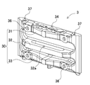
- FIG. 3 shows a perspective view of the end plate 3.
- the end plate 3 shown in this figure includes a plurality of strips 30.
- the intermediate strip 30 forms a space with the surface of the end plate 3.
- the end plate 3 having such a shape can be molded using, for example, a mold and a sand core.
- the end plate 3 is preferably made of a material such as iron, aluminum, aluminum alloy, or resin so that it can be molded with a mold such as a mold.
- the end plate 3 needs to suppress the expansion of the secondary battery cell.
- the secondary battery cell expands as shown by a broken line and an arrow in the perspective view of FIG. 4 due to charging and discharging.
- the outer can 1a of the secondary battery cell expands, there is a concern that the welded portion with the sealing plate 1b sealing the opening of the outer can 1a may come off.
- the exterior is provided between adjacent secondary battery cells. Since the opposing surfaces of the can 1a are pressed against each other, the expansion stress is offset and relaxed.
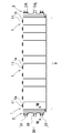
- the end plate 3 is provided with a plurality of strips 30 as shown in the side view of FIG.
- Each strip 30 is formed so as to protrude from the main surface of the end plate 3 in a substantially orthogonal posture.
- the first strip 31 is formed on the upper end side of the end plate 3
- the second strip 32 is formed in the middle
- the third strip 33 is formed on the lower end side.
- the first strip 31 and the second strip 32 are provided in portions of the main surface of the end plate 3 facing the upper surface and the lower surface of the outer can 1a. 3 to suppress the deformation of the end plate 3 so as to be stretched at the connection portion, and thus the expansion of the secondary battery cell 1 disposed on the end surface of the battery stack 2 can be suppressed.
- the connection interface between the can 1a and the sealing plate 1b can be protected.
- the bottom surface of the outer can 1a can be protected by the third band 33 on the bottom surface of the outer can 1a.
- the first strip 31 and the third strip 33 have a shape with the center protruding in a plan view.
- the band-like body can also be increased in rigidity by suppressing the deformation of the central portion so as to suppress the deformation of the central portion.
- the first strip 31 and the third strip 33 are formed in an isosceles triangle shape. Further, the vertices of the isosceles triangle shape are chamfered to prevent the end plate 3 from becoming large.
- the first through hole 36 for fastening the fastening member 4 is formed by using the first strip 31 and the third strip 33 formed thick on the surface of the end plate 3. The strength of the through hole 36 can be increased.
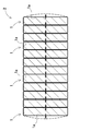
- FIG. 7 shows a horizontal sectional view taken along line VII-VII of the battery stack 2 of FIG.
- the outer can 1a of the secondary battery cell 1 disposed on the end face of the battery stack 2 in the horizontal section as well. Expands. In this portion, there is little trouble even if the outer can 1a is deformed. Accordingly, the second strip 32 provided in the middle forms a space 32a as shown in the horizontal sectional view of FIG.
- the second belt-like body 32 is formed in a U shape in plan view.
- the belly part of the expanded outer can 1a can be deformed so as to enter the space 32a.
- the stress to be deformed is applied to the intermediate region. The effect of relieving stress can be obtained by letting it escape.
- the second strip 32 is preferably formed with a thickness d2 thinner than the thickness d1 of the first strip 31.
- the said structure is only an example for implement
- the rigidity and strength of the end plate 3 for example, It is also possible to eliminate the double band resistance 32 and to be deformed only by a plane.
- the end plate 3 is preferably formed with a hole 34 in the upper end surface according to the required strength and rigidity.
- the rigidity balance can be adjusted by forming the hole 34 in the upper end surface.
- the hole 34 is not intended to allow the secondary battery cell 1 to expand at this portion. Therefore, the hole 34 is a space smaller than the space 32a formed by the second strip 32.
- a hole may be formed on the upper end surface according to the required strength and rigidity. This can further reduce the weight.
- the above power supply apparatus can be used as a vehicle-mounted power supply.
- a vehicle equipped with a power supply device an electric vehicle such as a hybrid vehicle or a plug-in hybrid vehicle that runs with both an engine and a motor, or an electric vehicle that runs only with a motor can be used, and it is used as a power source for these vehicles.
- a description will be given of an example in which a large-capacity, high-output power supply device 1000 in which a large number of the above-described power supply devices are connected in series or in parallel and a necessary control circuit is added is constructed. . (Power supply for hybrid vehicles)
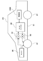
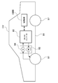
- FIG. 9 shows an example in which a power supply device is mounted on a hybrid vehicle that runs with both an engine and a motor.
- a vehicle HV equipped with the power supply device shown in this figure includes a vehicle main body 91, an engine 96 that travels the vehicle main body 91, and a travel motor 93, and wheels that are driven by the engine 96 and the travel motor 93. 97, a power supply device 1000 that supplies power to the motor 93, and a generator 94 that charges the battery of the power supply device 1000.
- the power supply apparatus 1000 is connected to a motor 93 and a generator 94 via a DC / AC inverter 95.
- the vehicle HV travels by both the motor 93 and the engine 96 while charging / discharging the battery of the power supply apparatus 1000.
- the motor 93 is driven to drive the vehicle when the engine efficiency is low, for example, during acceleration or low-speed driving.
- the motor 93 is driven by power supplied from the power supply apparatus 1000.
- the generator 94 is driven by the engine 96, or is driven by regenerative braking when the vehicle is braked, and charges the battery of the power supply apparatus 1000. (Power supply for electric vehicles)
- FIG. 10 shows an example in which a power supply device is mounted on an electric vehicle that runs only with a motor.
- a vehicle EV equipped with the power supply device shown in this figure supplies a power to the vehicle main body 91, a motor 93 for traveling the vehicle main body 91, wheels 97 driven by the motor 93, and the motor 93.
- a power generator 94 that charges the battery of the power supply device 1000.
- the power supply apparatus 100 is connected to a motor 93 and a generator 94 via a DC / AC inverter 95.
- the motor 93 is driven by power supplied from the power supply apparatus 1000.
- the generator 94 is driven by energy when regeneratively braking the vehicle EV and charges the battery of the power supply apparatus 1000. (Power storage system)
- the present invention does not specify the use of the power supply device as the power supply of the motor that drives the vehicle.
- the power supply apparatus according to the embodiment can also be used as a power supply for a power storage system that charges and stores a battery with power generated by solar power generation, wind power generation, or the like.
- FIG. 11 shows a power storage system in which a battery of the power supply apparatus 1000 is charged with a solar battery and stored. As shown in the figure, the power storage system shown in this figure charges the battery of the power supply device 100 with the power generated by the solar battery 82 arranged on the roof or rooftop of a building 81 such as a house or factory. Furthermore, this power storage system supplies the power stored in the power supply device 100 to the load 83 via the DC / AC inverter 85.
- the power supply device can also be used as a power supply for a power storage system that charges and stores a battery using late-night power at night.
- a power supply device charged with late-night power can be charged with late-night power, which is surplus power of the power plant, and can output power during the daytime when the power load increases, thereby limiting the daytime peak power to a small value.
- the power supply device can also be used as a power source that is charged by both the output of the solar cell and midnight power. This power supply device can efficiently store both electric power generated by a solar cell and late-night electric power while taking into account the weather and power consumption.
- the power storage system as described above includes a backup power supply device that can be mounted on a rack of a computer server, a backup power supply device for a wireless base station such as a mobile phone, a power storage power source for home use or a factory, a power source for a street light, etc. It can be suitably used for applications such as power storage devices combined with solar cells, backup power supplies such as traffic lights and traffic indicators for roads.
- Power supply device cooling method, cooling program, computer-readable recording medium and stored device, power supply device, and vehicle equipped with the same according to the present invention include electric vehicles such as hybrid vehicles, fuel cell vehicles, electric vehicles, and electric motorcycles. Can be suitably used as a power source for a large current used for a power source of a motor for driving the motor.
- a power supply device such as a plug-in hybrid electric vehicle, a hybrid electric vehicle, or an electric vehicle that can switch between the EV traveling mode and the HEV traveling mode can be used.
- a backup power supply device that can be mounted on a rack of a computer server, a backup power supply device for a wireless base station such as a mobile phone, a power storage device for home use and a factory, a power supply for a street light, etc. Also, it can be used as appropriate for applications such as a backup power source such as a traffic light.
- main-body part 41 ... fixing
Abstract
部分的に変形を許容しつつ、二次電池セルの拘束を維持できるエンドプレートを有する電源装置等を提供するために、複数の二次電池セルと、複数の二次電池セルを連結した電池積層体の端面に配置されて、この電池積層体を挟持する一対のエンドプレート(3)と、エンドプレート(3)同士を固定するための締結部材とを備える電源装置であって、エンドプレート(3)は、このエンドプレート(3)の上端側で、その主面から突出する第一帯状体(31)と、このエンドプレート(3)の中間で、その主面から突出する第二帯状体(32)とを有しており、第二帯状体(32)に、エンドプレート(3)の主面との間で空間(32a)を形成する。
Description
本発明は、電源装置及びこれを備える車両に関する。
電源装置は、車両の駆動用等に利用されている。このような電源装置は、多数の二次電池セルを直列や並列に接続して大電流を出力可能としている。近年は二次電池セルの高容量化が進んでおり、二次電池セルの加熱や類焼の対策をいかにして実現するかが課題となっている。特に、高容量の二次電池セルは電池エネルギーが高いことから、安全性の確保が重要となっている。
車載用のバッテリシステムでは、複数の二次電池セルをエンドプレートと締結部材で締結して構成される組電池が用いられている。特許文献1のような複数のリブを有する形状のエンドプレートは、強度と軽量化の観点で有効である。
一方、近年の二次電池セルの高容量化に伴い、二次電池セルの膨張量が大きくなる傾向がある。このような膨張量の大きい二次電池セルをエンドプレートと締結部材で締結すると、エンドプレートに応力が集中し、エンドプレートが破断するおそれがある。
本発明は、このような背景に鑑みてなされたものであり、その目的の一は、二次電池セルの部分的な変形を許容しつつ、二次電池セルの拘束を維持できるようなエンドプレートを有する電源装置及びこれを備える車両を提供することにある。
本発明の一実施形態に係る電源装置は、複数の二次電池セルと、前記複数の二次電池セルを連結した電池積層体の端面に配置されて、該電池積層体を挟持する一対のエンドプレートであって、それぞれのエンドプレートが上端部分の剛性が中央部分の剛性よりも強い、該一対のエンドプレートと、前記エンドプレート同士を固定するための締結部材とを備える。
上記構成により、電池積層体の端面に位置する二次電池セルの膨張をエンドプレートでもって抑制し、この二次電池セルを保護することが可能となる。
本発明の一実施形態に係る電源装置は、複数の二次電池セルと、前記複数の二次電池セルを連結した電池積層体の端面に配置されて、該電池積層体を挟持する一対のエンドプレートと、前記エンドプレート同士を固定するための締結部材とを備える。前記エンドプレートは、該エンドプレートの上端側で、その主面から突出する第一帯状体と、該エンドプレートの中間で、その主面から突出する第二帯状体と、を有しており、前記第二帯状体に、前記エンドプレートの主面との間で空間を形成している。
上記構成によれば、電池積層体の端面に位置する二次電池セルの膨張をエンドプレートでもって抑制し、この二次電池セルを保護することが可能となる。
また、本発明の他の実施形態に係る電源装置は、複数の二次電池セルと、前記複数の二次電池セルを連結した電池積層体の端面に配置されて、該電池積層体を挟持する一対のエンドプレートと、前記エンドプレート同士を固定するための締結部材とを備える。前記エンドプレートは、該エンドプレートの上端側で、その主面から突出する第一帯状体と、該エンドプレートの中間で、その主面から突出する第二帯状体と、を有しており、前記第二帯状体に、前記エンドプレートの主面との間で空間を形成している。
上記構成によれば、中間付近の剛性が低く、上端側の剛性が高いエンドプレートが電池積層体を挟持する構成となるので、二次電池セルの封口体付近の膨張を抑制しつつ、二次電池セルの中央部分の膨張を許容することで、締結部材やエンドプレートに係る負荷を低減できる。
また、前記エンドプレートが、該エンドプレートの下端側で、その主面から突出する第三帯状体を有する構成としても良い。上記構成により、電池積層体の端面に位置する二次電池セルの下端側の変形を抑制できる。
また、前記第二帯状体の厚さを、前記第一帯状体よりも薄く形成してもよい。上記構成により、電池積層体の端面に位置する二次電池セルの中央部分での変形がさらに許容され、変形の全体の応力を緩和することができる。
さらに、前記第一帯状体と第三帯状体を、中央部分を突出させた形状としてもよい。上記構成により、電池積層体の端面に位置する二次電池セルの上面と底面の変形を抑制してこれを保護することが可能となる。
さらにまた、前記第一帯状体と第三帯状体に、前記締結部材を固定するための第一貫通孔を設けてもよい。
さらにまた、前記エンドプレートを、型を用いて成形可能な鉄系、アルミニウム、アルミニウム合金、樹脂等の材料としてもよい。上記構成により、エンドプレートの剛性を高めることができる。
さらにまた、前記エンドプレートの上端面に穴部を形成してもよい。上記構成により、軽量化を図ることができる。
さらにまた、前記エンドプレートの下端面に穴部を形成してもよい。上記構成により、軽量化を図ることができる。
本発明の一実施形態に係る車両は、前記電源装置と、該電源装置から電力供給される走行用のモータと、前記電源装置及び前記モータを搭載してなる車両本体と、前記モータで駆動されて前記車両本体を走行させる車輪とを備える。
本発明の一実施形態に係るエンドプレートは、電極端子を有する二次電池セルを複数積層した状態で、該積層された二次電池セルの積層体を挟持するためのエンドプレートであって、前記エンドプレートの上端側で、その主面から突出する第一帯状体と、前記エンドプレートの中間で、その主面から突出する第二帯状体とを有しており、前記第二帯状体に、前記エンドプレートの主面との間で空間を形成している。上記構成によれば、中間付近の剛性が低く、上端側の剛性が高いエンドプレートが電池積層体を挟持する構成となるので、二次電池セルの封口体付近の膨張を抑制しつつ、二次電池セルの中央部分の膨張を許容することで、締結部材やエンドプレートに係る負荷を低減できる。
以下、本発明の実施形態を図面に基づいて説明する。ただし、以下に示す実施形態は、本発明の技術思想を具体化するための例示であって、本発明は以下のものに特定されない。また、本明細書は特許請求の範囲に示される部材を、実施形態の部材に特定するものでは決してない。特に実施形態に記載されている構成部品の寸法、材質、形状、その相対的配置等は特に特定的な記載がない限りは、本発明の範囲をそれのみに限定する趣旨ではなく、単なる説明例にすぎない。なお、各図面が示す部材の大きさや位置関係等は、説明を明確にするため誇張していることがある。さらに以下の説明において、同一の名称、符号については同一若しくは同質の部材を示しており、詳細説明を適宜省略する。さらに、本発明を構成する各要素は、複数の要素を同一の部材で構成して一の部材で複数の要素を兼用する態様としてもよいし、逆に一の部材の機能を複数の部材で分担して実現することもできる。
実施形態に係る電源装置は、ハイブリッド車や電気自動車などの電動車両に搭載されて走行モータに電力を供給する電源、太陽光発電や風力発電などの自然エネルギーの発電電力を蓄電する電源、あるいは深夜電力を蓄電する電源など、種々の用途に使用され、とくに大電力、大電流の用途に好適な電源として使用される。
[実施形態1]
[実施形態1]
本発明の実施形態1に係る電源装置100の斜視図を図1に、その分解斜視図を図2に、それぞれ示す。これらの図に示す電源装置100は、複数の二次電池セル1を積層している電池積層体2と、この電池積層体2の両端に配置された一対のエンドプレート3と、一対のエンドプレート3に両端が連結されて、電池積層体2を締結する一対の締結部材4とを備えている。さらに、電源装置100は、締結部材4が、電池積層体2の側面に沿って配置される本体部40と、この本体部40の両端で折曲されて、エンドプレート3の外側面に固定される固定部41とを備えている。
(二次電池セル1)
(二次電池セル1)
二次電池セル1は、図2に示すように、厚さに比べて幅が広い、言い換えると幅よりも薄い角形電池で、厚さ方向に積層されて電池積層体2としている。二次電池セル1はリチウムイオン二次電池である。ただし、二次電池セルは、ニッケル水素電池、ニッケルカドミウム電池等、充電できる全ての二次電池とすることもできる。二次電池セル1は、密閉構造の外装缶1aに正負の電極板を電解液と共に収容している。外装缶1aは、アルミニウムやアルミニウム合金等の金属板を角形にプレス成形され、開口部を封口板1bで気密に密閉している。封口板1bは、外装缶1aと同じアルミニウムやアルミニウム合金で、両端部に正負の電極端子11を固定している。さらに、封口板1bは、正負の電極端子11の間に、ガス排出弁15を設けている。
複数の二次電池セル1は、各二次電池セル1の厚み方向が積層方向となるように積層されて電池積層体2を構成している。二次電池セル1は、正負の電極端子11を設けている端子面10を同一平面に配置して、複数の二次電池セル1を積層して電池積層体2としている。
(セパレータ12)
(セパレータ12)
電池積層体2は、図2に示すように、積層している二次電池セル1の間にセパレータ12を挟着している。図のセパレータ12は、絶縁材で薄いプレート状またはシート状に製作されている。図に示すセパレータ12は、二次電池セル1の対向面とほぼ等しい大きさのプレート状としており、このセパレータ12を互いに隣接する二次電池セル1の間に積層して、隣接する二次電池セル1同士を絶縁している。なお、図示はしないが、セパレータ12は、二次電池セル1とスペーサの間に冷却気体の流路が形成される形状としてもよい。また、二次電池セル1の表面を絶縁材で被覆することもできる。例えばPET樹脂等のシュリンクチューブで二次電池セルの電極部分を除く外装缶1aの表面を熱溶着させてもよい。
(電池積層体2)
(電池積層体2)
電池積層体2は、隣接する二次電池セル1の正負の電極端子11に金属製のバスバーが接続されて、バスバーでもって複数の二次電池セル1を直列又は並列に、あるいは直列と並列に接続される。図に示す電池積層体2は、12個の二次電池セル1を直列に接続している。ただ、本発明は、電池積層体を構成する二次電池セル1の個数とその接続状態を特定しない。
(端面スペーサ13)
(端面スペーサ13)
電池積層体2は、両端面に端面スペーサ13を挟んでエンドプレート3を配置している。端面スペーサ13は、図2に示すように、電池積層体2とエンドプレート3との間に配置されてエンドプレート3を電池積層体2から絶縁する。端面スペーサ13は、上述したセパレータ12と同様の材質で構成することができる。図に示す端面スペーサ13は、二次電池セル1の対向面全体をカバーできる大きさのプレート部13Xを備えており、このプレート部13Xを電池積層体2の両端に配置された二次電池セル1とエンドプレート3との間に積層している。
さらに、図2の端面スペーサ13は、二次電池セル1の端子面10をカバーする端子面カバー部13Aを、プレート部13Xの上端縁に連結して設けている。図2の端面スペーサ13は、プレート部13Xの上端縁の全体にわたって、二次電池セル1側に突出する端子面カバー部13Aを設けている。このように、プレート部13Xの上端縁の全体にわたって端子面カバー部13Aを設ける構造は、エンドプレート3と電池積層体2との絶縁距離を確保しながら、二次電池セル1の上面である端子面10を確実にカバーして絶縁特性を向上できる。
(エンドプレート3)
(エンドプレート3)
エンドプレート3は、図1と図2に示すように、電池積層体2の両端に配置されると共に、電池積層体2の両側面に沿って配置される締結部材4を介して締結される。エンドプレート3は、電池積層体2の二次電池セル1の積層方向における両端であって、端面スペーサ13の外側に配置されて電池積層体2を両端から挟着している。各エンドプレートは、上端部分の剛性を中央部分の剛性よりも強くすることができる。
エンドプレート3は、外形を四角形としており、電池積層体2の端面に対向して配置されている。図1と図2に示すエンドプレート3は、二次電池セル1の外形とほぼ等しい外形としている。ずなわち、図に示すエンドプレート3は、左右方向の幅を二次電池セル1の幅と等しくすると共に、上下方向の高さを二次電池セル1の高さと等しくしている。なお、本明細書において、上下方向とは図における上下方向とし、左右方向は、図における左右方向であって、電池の積層方向と直交する水平方向を意味するものとする。
さらに、図2に示すエンドプレート3は、エンドプレート3を固定するための貫通孔を複数形成している。例えばエンドプレート3は、締結部材4の固定部41を固定する留め具19を挿入するための第一貫通孔36を有している。図に示すエンドプレート3は、第一貫通孔36として、複数の貫通孔を開口している。図のエンドプレート3は、両側部であって固定部41と対向する位置に、上下に離して複数の第一貫通孔36を設けている。図2のエンドプレート3は、両側に沿って3個ずつ、全体で6個の第一貫通孔36を設けている。このエンドプレート3は、外周面に配置される固定部41を貫通する留め具19が第一貫通孔36に挿入される。第一貫通孔36に挿入された留め具19は、第一貫通孔36に固定されて固定部41を定位置に固定する。
さらにエンドプレート3は、第一貫通孔36とは異なる第二貫通孔37として、電源装置を固定部位(例えば車載用の電源装置においては、車両)に固定するボルトを挿入するための貫通孔を形成している。第二貫通孔37は、エンドプレート3の上面において両端に縦穴として貫通されている。
(留め具19)
(留め具19)
留め具19は、第一貫通孔36に抜けないように固定される。このような留め具19として、止ネジやボルト、リベット等が使用できる。止ネジやボルトである留め具は、第一貫通孔36に挿入する際に、第一貫通孔36に螺合して固定される。したがって、止ネジやボルトである留め具が固定される第一貫通孔36は、内面に止ネジやボルトの雄ネジと噛み合う雌ネジを設けることができる。また、リベットである留め具は、固定部を貫通する状態でエンドプレート3の第一貫通孔36に挿入されると共に、第一貫通孔36の内部において一端がかしめられてエンドプレート3と固定部とを固定する。リベットである留め具は、エンドプレート3の第一貫通孔36の内部で形成されるカシメ部によって、エンドプレート3の第一貫通孔36と固定部の貫通孔の開口縁部とを挟着して、固定部をエンドプレート3に固定する。リベットが挿入される第一貫通孔36は、外側面の開口面積を小さくしてリベットの頭部を通過できない内形とすると共に、反対側である対向面側の開口面積を大きくして、リベットを変形させて形成されるカシメ部を内部に配置できる構造とすることができる。
(締結部材4)
(締結部材4)
締結部材4は、図1と図2に示すように、電池積層体2の積層方向に延長されており、両端が電池積層体2の両端面に配置されたエンドプレート3に固定されて、このエンドプレート3を介して電池積層体2を積層方向に締結している。締結部材4は、電池積層体2の側面に沿う所定の幅と所定の厚さを有する金属板で、電池積層体2の両側面に対向して配置されている。この締結部材4には、鉄などの金属板、好ましくは、鋼板が使用できる。金属板からなる締結部材4は、プレス成形等により折曲加工されて所定の形状に形成される。
締結部材4は、電池積層体2の側面に沿って配置される本体部40と、この本体部40の両端で折曲されて、エンドプレート3の外側面に固定される固定部41とを備えている。本体部40は、電池積層体2と、その両端に配置されるエンドプレート3のほぼ全体を被覆する大きさの矩形状としている。図1に示す本体部40は、電池積層体2の側面のほぼ全面を隙間なく被覆している。ただ、本体部40は、1以上の開口部を設けて、電池積層体の側面の一部を表出させることもできる。締結部材4は、両端を一対のエンドプレート3に固定するために、その両端部をエンドプレート3の外側面に沿うように折曲加工して固定部41を設けている。図に示す固定部41は、本体部40及びエンドプレート3の上下方向の高さとほぼ等しくして、エンドプレート3の左右の両側部を被覆している。この締結部材4は、固定部41の先端に設けた貫通孔42に挿入される留め具19を介してエンドプレート3に固定される。さらに、図に示す締結部材4は、本体部40の両端部を除く中間部分の上端部に沿って、電池積層体2の上面及び下面を保持する折曲部44を備えている。折曲部44は、電池積層体2を構成する二次電池セル1の上面及び下面を保持して、各二次電池セル1の端子面10の位置が上下にずれるのを抑制している。
なお、締結部材4は、図示しないが、本体部40と折曲部44の内面に絶縁シートを配置して、この絶縁シートにより、電池積層体2の二次電池セル1と締結部材4とを絶縁することができる。さらに、締結部材4は、図示しないが、本体部40の両端部の内面に緩衝材を配置して、エンドプレート3の両側面を振動等の衝撃から保護することもできる。
(帯状体)
(帯状体)
図3にエンドプレート3の斜視図を示す。この図に示すエンドプレート3は、複数の帯状体30を備える。中間の帯状体30は、エンドプレート3の表面との間で空間を形成している。このような形状のエンドプレート3は、例えば、鋳型と、砂型である中子を用いて成形することが可能である。なお、エンドプレート3は、鋳型のような型で成形できるように、鉄系、アルミニウム、アルミニウム合金、樹脂等の材料製とすることが好ましい。
エンドプレート3は、二次電池セルの膨張を抑制する必要がある。二次電池セルは、充放電により、図4の斜視図において破線及び矢印で示すように膨張する。二次電池セルの外装缶1aが膨張すると、この外装缶1aの開口部を封止している封口板1bとの溶接部位が外れることが懸念される。ここで、角型の二次電池セルを積層した電池積層体2で考えると、図5の側面図に示すように、電池積層体2の中間の部位では、隣接する二次電池セル間で外装缶1aの対向する面同士が相互に押し合うため、膨張の応力は相殺され、緩和される。その一方で電池積層体2の端面に位置する二次電池セルの、外装缶1aの外側の面においては、対向する二次電池セルが存在しないため膨張の応力が働き、図4で示したように外装缶1aと封口板1bの溶接部分を保護する必要がある。
このため本実施形態に係るエンドプレート3は、図6の側面図に示すように、複数の帯状体30を付加している。各帯状体30は、エンドプレート3の主面からほぼ直交する姿勢で突出するように形成される。図6の例では、エンドプレート3の上端側に第一帯状体31を、中間に第二帯状体32を、下端側に第三帯状体33を、それぞれ形成している。これらの帯状体30は、エンドプレート3と一体に形成される。
このように第一帯状体31と第二帯状体32を、エンドプレート3の主面の内、外装缶1aの上面と下面に面する部位に設けたことで、第一帯状体31とエンドプレート3との接続部位で突っ張るようにしてエンドプレート3の変形を抑制して、もって電池積層体2の端面に配置された二次電池セル1の膨張を抑制でき、この二次電池セル1の外装缶1aと封口板1bとの接続界面を保護できる。また外装缶1aの底面においても、同様に第三帯状体33でもって、外装缶1aの底面を保護できる。
また第一帯状体31と第三帯状体33は、平面視において中央を突出させた形状とすることが好ましい。特に二次電池セル1の上面において、中央の部分の変形を抑制するよう、帯状体もこの部分を厚く形成することで剛性を高めることができる。図3に示す例においては、第一帯状体31と第三帯状体33を二等辺三角形状に形成している。また、二等辺三角形状の頂点は面取りして、エンドプレート3が大型化することを抑制している。
さらに第一帯状体31と第三帯状体33に、締結部材4の固定部41を固定する留め具19を挿入するための第一貫通孔36を設けることが好ましい。このように、エンドプレート3の表面に厚く形成された第一帯状体31と第三帯状体33を利用して、締結部材4の締結用の第一貫通孔36を形成することで、第一貫通孔36の強度を高めることができる。
一方、外装缶1aの内、封口板1bとの接続界面や底面以外の部位、すなわち中間の領域においては、膨張を許容してもよい。ここで図5の電池積層体2のVII-VII線における水平断面図を図7に示す。この図に示すように、二次電池セル1が破線及び矢印で示すように膨張する結果、水平断面においても同様に、電池積層体2の端面に配置された二次電池セル1の外装缶1aが膨張する。この部分においては、外装缶1aが変形しても支障が少ない。そこで、中間に設けられた第二帯状体32については、図8の水平断面図に示すように空間32aを形成している。いいかえると、第二帯状体32は平面視においてコ字状に形成されている。このような形状としたことで、膨張した外装缶1aの腹の部分が空間32a内に侵入するようにして変形できる。換言すると、外装缶1aの変形の内、上面側と下面側の近傍については変形を抑制しつつ、中間の腹の部分については変形を許容することで、変形しようとする応力を中間の領域に逃がすようにして、応力を緩和する効果が得られる。
また第二帯状体32は、図6に示すようにその厚さd2を、第一帯状体31の厚さd1よりも薄く形成することが好ましい。このようにすることで、電池積層体2の端面に位置する二次電池セル1に対して、上面や下面と比較して中央部分での押圧力を相対的に弱めて、変形を許容できる。いいかえると意図的に中央部分の帯状体の剛性を弱くすることで、上面や下面側での応力の集中を避けて中央に逃がすことで、上面と下面の保護を図ることができる。また第二帯状体32を薄くすることで、空間32aを形成することと相俟って第二帯状体32の重量を低減し、エンドプレート3の軽量化が図られる。
なお、上記構成は、電池積層体の端面に位置する二次電池セルの膨張を抑制しつつ、この二次電池セルを保護することを実現するための一例に過ぎない。上記目的を達成するためには、上端部分の剛性が強く、かつ、中央部分の剛性を弱くしたエンドプレートを提供することが特に重要であり、エンドプレート3の剛性や強度によっては、例えば、第二帯状耐32をなくして、平面のみで変形を受けるような構成とすることもできる。
さらにエンドプレート3は、図3の斜視図に示すように必要とする強度や剛性に応じて上端面に穴部34を形成することが好ましい。例えば、上端部分の剛性を強くしすぎると、エンドプレートの他の部分に応力が集中する部分ができることがある。そのため、エンドプレートの強度の観点で考えると、必ずしも、上端部分の剛性が強いほどよいというわけではない。上記構成では、上端面に穴部34を形成することで、剛性のバランスを整えることができる。なお、穴部34には、第二帯状体32によって形成される空間32aとは異なり、この部分で二次電池セル1の膨張を許容するという意図はない。そのため、穴部34は、第二帯状体32によって形成される空間32aよりも小さい空間である。また、図示はしないが、必要とする強度や剛性に応じて、上端面に穴部を形成しても良い。これによってさらに軽量化を図ることができる。
以上の電源装置は、車載用の電源として利用できる。電源装置を搭載する車両としては、エンジンとモータの両方で走行するハイブリッド車やプラグインハイブリッド車、あるいはモータのみで走行する電気自動車等の電動車両が利用でき、これらの車両の電源として使用される。なお、車両を駆動する電力を得るために、上述した電源装置を直列や並列に多数接続して、さらに必要な制御回路を付加した大容量、高出力の電源装置1000を構築した例として説明する。
(ハイブリッド車用電源装置)
(ハイブリッド車用電源装置)
図9は、エンジンとモータの両方で走行するハイブリッド車に電源装置を搭載する例を示す。この図に示す電源装置を搭載した車両HVは、車両本体91と、この車両本体91を走行させるエンジン96及び走行用のモータ93と、これらのエンジン96及び走行用のモータ93で駆動される車輪97と、モータ93に電力を供給する電源装置1000と、電源装置1000の電池を充電する発電機94とを備えている。電源装置1000は、DC/ACインバータ95を介してモータ93と発電機94に接続している。車両HVは、電源装置1000の電池を充放電しながらモータ93とエンジン96の両方で走行する。モータ93は、エンジン効率の悪い領域、例えば加速時や低速走行時に駆動されて車両を走行させる。モータ93は、電源装置1000から電力が供給されて駆動する。発電機94は、エンジン96で駆動され、あるいは車両にブレーキをかけるときの回生制動で駆動されて、電源装置1000の電池を充電する。
(電気自動車用電源装置)
(電気自動車用電源装置)
また、図10は、モータのみで走行する電気自動車に電源装置を搭載する例を示す。この図に示す電源装置を搭載した車両EVは、車両本体91と、この車両本体91を走行させる走行用のモータ93と、このモータ93で駆動される車輪97と、このモータ93に電力を供給する電源装置1000と、この電源装置1000の電池を充電する発電機94とを備えている。電源装置100は、DC/ACインバータ95を介してモータ93と発電機94に接続している。モータ93は、電源装置1000から電力が供給されて駆動する。発電機94は、車両EVを回生制動する時のエネルギーで駆動されて、電源装置1000の電池を充電する。
(蓄電システム)
(蓄電システム)
さらに、本発明は、電源装置の用途を、車両を走行させるモータの電源には特定しない。実施形態に係る電源装置は、太陽光発電や風力発電等で発電された電力で電池を充電して蓄電する蓄電システムの電源として使用することもできる。図11は、電源装置1000の電池を太陽電池で充電して蓄電する蓄電システムを示す。この図に示す蓄電システムは、図に示すように、家屋や工場等の建物81の屋根や屋上等に配置された太陽電池82で発電される電力で、電源装置100の電池を充電する。さらに、この蓄電システムは、電源装置100に蓄電した電力を、DC/ACインバータ85を介して負荷83に供給する。
さらに、電源装置は、図示しないが、夜間の深夜電力を利用して電池を充電して蓄電する蓄電システムの電源として使用することもできる。深夜電力で充電される電源装置は、発電所の余剰電力である深夜電力で充電して、電力負荷の大きくなる昼間に電力を出力して、昼間のピーク電力を小さく制限することができる。さらに、電源装置は、太陽電池の出力と深夜電力の両方で充電する電源としても使用できる。この電源装置は、太陽電池で発電される電力と深夜電力の両方を有効に利用して、天候や消費電力を考慮しながら効率よく蓄電できる。
以上のような蓄電システムは、コンピュータサーバのラックに搭載可能なバックアップ電源装置、携帯電話等の無線基地局用のバックアップ電源装置、家庭内用または工場用の蓄電用電源、街路灯の電源等、太陽電池と組み合わせた蓄電装置、信号機や道路用の交通表示器などのバックアップ電源用などの用途に好適に利用できる。
本発明に係る電源装置の冷却方法、冷却プログラム、コンピュータで読み取り可能な記録媒体及び記憶した機器、電源装置並びにこれを備える車両は、ハイブリッド車、燃料電池自動車、電気自動車、電動オートバイ等の電動車両を駆動するモータの電源用等に使用される大電流用の電源として好適に利用できる。例えばEV走行モードとHEV走行モードとを切り替え可能なプラグイン式ハイブリッド電気自動車やハイブリッド式電気自動車、電気自動車等の電源装置が挙げられる。またコンピュータサーバのラックに搭載可能なバックアップ電源装置、携帯電話等の無線基地局用のバックアップ電源装置、家庭内用、工場用の蓄電用電源、街路灯の電源等、太陽電池と組み合わせた蓄電装置、信号機等のバックアップ電源用等の用途にも適宜利用できる。
1…二次電池セル、1a…外装缶、1b…封口板、2…電池積層体、3…エンドプレート、4…締結部材、10…端子面、11…電極端子、12…セパレータ、13…端面スペーサ、13X…プレート部、13A…端子面カバー部、15…ガス排出弁、19…留め具、30…帯状体、31…第一帯状体、32…第二帯状体、32a…空間、33…第三帯状体、34…穴部、36…第一貫通孔、37…第二貫通孔、40…本体部、41…固定部、42…貫通孔、44…折曲部、81…建物、82…太陽電池、83…負荷、85…DC/ACインバータ、91…車両本体、93…モータ、94…発電機、95…DC/ACインバータ、96…エンジン、97…車輪、100…電源装置、1000…電源装置、HV…車両、EV…車両
Claims (11)
- 複数の二次電池セルと、
前記複数の二次電池セルを連結した電池積層体の端面に配置されて、該電池積層体を挟持する一対のエンドプレートであって、それぞれのエンドプレートが上端部分の剛性が中央部分の剛性よりも強い、該一対のエンドプレートと、
前記エンドプレート同士を固定するための締結部材と
を備える電源装置。 - 複数の二次電池セルと、
前記複数の二次電池セルを連結した電池積層体の端面に配置されて、該電池積層体を挟持する一対のエンドプレートと、
前記エンドプレート同士を固定するための締結部材とを備える電源装置であって、
前記エンドプレートは、
該エンドプレートの上端側で、その主面から突出する第一帯状体と、
該エンドプレートの中間で、その主面から突出する第二帯状体と、を有しており、
前記第二帯状体は、前記エンドプレートの主面との間で空間を形成してなる電源装置。 - 請求項1又は2に記載の電源装置であって、
前記エンドプレートがさらに、
該エンドプレートの下端側で、その主面から突出する第三帯状体を有してなる電源装置。 - 請求項1~3のいずれか一項に記載の電源装置であって、
前記第二帯状体の厚さが、前記第一帯状体よりも薄く形成されてなる電源装置。 - 請求項1~4のいずれか一項に記載の電源装置であって、
前記第一帯状体と第三帯状体を、中央部分を突出させた形状としてなる電源装置。 - 請求項5に記載の電源装置であって、
前記第一帯状体と第三帯状体は、前記締結部材を固定するための第一貫通孔を設けてなる電源装置。 - 請求項1~6のいずれか一項に記載の電源装置であって、
前記エンドプレートは、型を用いて成形可能な鉄系、アルミニウム、アルミニウム合金、又は樹脂のいずれかの材料製としてなる電源装置。 - 請求項1~7のいずれか一項に記載の電源装置であって、
前記エンドプレートは、上端面に穴部を形成してなる電源装置。 - 請求項1~8のいずれか一項に記載の電源装置であって、
前記エンドプレートは、下端面に穴部を形成してなる電源装置。 - 請求項1~9のいずれか一に記載の電源装置を備える車両であって、
前記電源装置と、該電源装置から電力供給される走行用のモータと、前記電源装置及び前記モータを搭載してなる車両本体と、前記モータで駆動されて前記車両本体を走行させる車輪とを備える車両。 - 電極端子を有する二次電池セルを複数積層した状態で、該積層された二次電池セルの積層体を挟持するためのエンドプレートであって、
前記エンドプレートの上端側で、その主面から突出する第一帯状体と、
前記エンドプレートの中間で、その主面から突出する第二帯状体と、を有しており、
前記第二帯状体は、前記エンドプレートの主面との間で空間を形成してなるエンドプレート。
Priority Applications (4)
| Application Number | Priority Date | Filing Date | Title |
|---|---|---|---|
| CN201880092116.9A CN111937178B (zh) | 2018-03-30 | 2018-11-16 | 电源装置以及具有该电源装置的车辆 |
| EP18912432.4A EP3780140A4 (en) | 2018-03-30 | 2018-11-16 | POWER SUPPLY DEVICE AND VEHICLE WITH POWER SUPPLY DEVICE |
| US16/981,724 US11817593B2 (en) | 2018-03-30 | 2018-11-16 | Power supply device and vehicle provided with power supply device |
| JP2020509607A JP7200223B2 (ja) | 2018-03-30 | 2018-11-16 | 電源装置及びこれを備える車両 |
Applications Claiming Priority (2)
| Application Number | Priority Date | Filing Date | Title |
|---|---|---|---|
| JP2018069572 | 2018-03-30 | ||
| JP2018-069572 | 2018-03-30 |
Publications (1)
| Publication Number | Publication Date |
|---|---|
| WO2019187314A1 true WO2019187314A1 (ja) | 2019-10-03 |
Family
ID=68060983
Family Applications (1)
| Application Number | Title | Priority Date | Filing Date |
|---|---|---|---|
| PCT/JP2018/042378 WO2019187314A1 (ja) | 2018-03-30 | 2018-11-16 | 電源装置及びこれを備える車両 |
Country Status (5)
| Country | Link |
|---|---|
| US (1) | US11817593B2 (ja) |
| EP (1) | EP3780140A4 (ja) |
| JP (1) | JP7200223B2 (ja) |
| CN (1) | CN111937178B (ja) |
| WO (1) | WO2019187314A1 (ja) |
Cited By (2)
| Publication number | Priority date | Publication date | Assignee | Title |
|---|---|---|---|---|
| WO2023053831A1 (ja) * | 2021-09-28 | 2023-04-06 | 株式会社Gsユアサ | 蓄電装置 |
| JP7459516B2 (ja) | 2020-01-14 | 2024-04-02 | 株式会社Gsユアサ | 蓄電装置 |
Families Citing this family (1)
| Publication number | Priority date | Publication date | Assignee | Title |
|---|---|---|---|---|
| JP7385629B2 (ja) * | 2021-07-06 | 2023-11-22 | プライムプラネットエナジー&ソリューションズ株式会社 | 蓄電モジュールおよび蓄電パック |
Citations (5)
| Publication number | Priority date | Publication date | Assignee | Title |
|---|---|---|---|---|
| JPH09120808A (ja) | 1995-10-24 | 1997-05-06 | Matsushita Electric Ind Co Ltd | 積層密閉形アルカリ蓄電池 |
| JP2007073509A (ja) * | 2005-09-05 | 2007-03-22 | Samsung Sdi Co Ltd | 電池モジュール |
| JP2015011989A (ja) * | 2013-06-27 | 2015-01-19 | 三星エスディアイ株式会社Samsung SDI Co.,Ltd. | バッテリモジュール |
| JP2015111493A (ja) * | 2012-03-28 | 2015-06-18 | 三洋電機株式会社 | 電源装置及びこれを備える車両並びに蓄電装置 |
| JP2015207553A (ja) * | 2014-04-11 | 2015-11-19 | パナソニックIpマネジメント株式会社 | 組電池 |
Family Cites Families (4)
| Publication number | Priority date | Publication date | Assignee | Title |
|---|---|---|---|---|
| JP4772614B2 (ja) * | 2005-07-29 | 2011-09-14 | 三星エスディアイ株式会社 | 電池モジュール |
| WO2013084756A1 (ja) * | 2011-12-10 | 2013-06-13 | 三洋電機株式会社 | 電源装置及びこれを備える車両並びに蓄電装置 |
| KR101772115B1 (ko) * | 2013-09-03 | 2017-08-28 | 삼성에스디아이 주식회사 | 유동 방지부를 포함하는 배터리 팩 |
| US10658635B2 (en) * | 2014-11-28 | 2020-05-19 | Sanyo Electric Co., Ltd. | Battery pack and vehicle equipped with same |
-
2018
- 2018-11-16 CN CN201880092116.9A patent/CN111937178B/zh active Active
- 2018-11-16 US US16/981,724 patent/US11817593B2/en active Active
- 2018-11-16 JP JP2020509607A patent/JP7200223B2/ja active Active
- 2018-11-16 WO PCT/JP2018/042378 patent/WO2019187314A1/ja active Application Filing
- 2018-11-16 EP EP18912432.4A patent/EP3780140A4/en active Pending
Patent Citations (5)
| Publication number | Priority date | Publication date | Assignee | Title |
|---|---|---|---|---|
| JPH09120808A (ja) | 1995-10-24 | 1997-05-06 | Matsushita Electric Ind Co Ltd | 積層密閉形アルカリ蓄電池 |
| JP2007073509A (ja) * | 2005-09-05 | 2007-03-22 | Samsung Sdi Co Ltd | 電池モジュール |
| JP2015111493A (ja) * | 2012-03-28 | 2015-06-18 | 三洋電機株式会社 | 電源装置及びこれを備える車両並びに蓄電装置 |
| JP2015011989A (ja) * | 2013-06-27 | 2015-01-19 | 三星エスディアイ株式会社Samsung SDI Co.,Ltd. | バッテリモジュール |
| JP2015207553A (ja) * | 2014-04-11 | 2015-11-19 | パナソニックIpマネジメント株式会社 | 組電池 |
Cited By (2)
| Publication number | Priority date | Publication date | Assignee | Title |
|---|---|---|---|---|
| JP7459516B2 (ja) | 2020-01-14 | 2024-04-02 | 株式会社Gsユアサ | 蓄電装置 |
| WO2023053831A1 (ja) * | 2021-09-28 | 2023-04-06 | 株式会社Gsユアサ | 蓄電装置 |
Also Published As
| Publication number | Publication date |
|---|---|
| EP3780140A4 (en) | 2021-05-26 |
| JP7200223B2 (ja) | 2023-01-06 |
| US20210376418A1 (en) | 2021-12-02 |
| EP3780140A1 (en) | 2021-02-17 |
| JPWO2019187314A1 (ja) | 2021-04-08 |
| CN111937178B (zh) | 2023-10-17 |
| US11817593B2 (en) | 2023-11-14 |
| CN111937178A (zh) | 2020-11-13 |
Similar Documents
| Publication | Publication Date | Title |
|---|---|---|
| JP7146744B2 (ja) | 電源装置及びこれを備える車両、蓄電装置並びに電源装置用セパレータ | |
| US20230098629A1 (en) | Power supply device, vehicle provided with same, and power storage device | |
| WO2020031737A1 (ja) | 電源装置及びこれを備える車両 | |
| JP7348174B2 (ja) | 電池モジュール及びこれを備える車両 | |
| CN114303279A (zh) | 电源装置和使用该电源装置的电动车辆以及蓄电装置 | |
| WO2020059296A1 (ja) | 電源装置及び電源装置を備える車両並びに蓄電装置 | |
| WO2019187314A1 (ja) | 電源装置及びこれを備える車両 | |
| CN113632300B (zh) | 电源装置和使用该电源装置的电动车辆以及蓄电装置 | |
| JPWO2020026964A1 (ja) | 電源装置及びこれを備える車両並びに緩衝体 | |
| WO2020194937A1 (ja) | 電源装置及びこれを用いた電動車両並びに蓄電装置 | |
| US20230178844A1 (en) | Power supply device, and vehicle and electrical storage device each equipped with same | |
| US20220367936A1 (en) | Power source device, electric vehicle equipped with said power source device, and power storage device | |
| JP7387223B2 (ja) | 電源装置とこの電源装置を備える電動車両及び蓄電装置 | |
| CN115004472A (zh) | 电源装置、具备该电源装置的车辆以及蓄电装置 | |
| US20230246274A1 (en) | Power source device, and vehicle and power storage device each equipped with same | |
| WO2021157139A1 (ja) | 電源装置及びこれを用いた電動車両並びに蓄電装置 | |
| EP4131563A1 (en) | Power source device, and vehicle and power storage device each equipped with same | |
| WO2020194930A1 (ja) | 電源装置及びこれを用いた電動車両並びに蓄電装置 | |
| JP2022123152A (ja) | 電源装置とこの電源装置を備える電動車両及び蓄電装置 | |
| CN114175375A (zh) | 电源装置和使用该电源装置的电动车辆以及蓄电装置 |
Legal Events
| Date | Code | Title | Description |
|---|---|---|---|
| 121 | Ep: the epo has been informed by wipo that ep was designated in this application |
Ref document number: 18912432 Country of ref document: EP Kind code of ref document: A1 |
|
| ENP | Entry into the national phase |
Ref document number: 2020509607 Country of ref document: JP Kind code of ref document: A |
|
| WWE | Wipo information: entry into national phase |
Ref document number: 2018912432 Country of ref document: EP |