WO2018207401A1 - スパークプラグ - Google Patents
スパークプラグ Download PDFInfo
- Publication number
- WO2018207401A1 WO2018207401A1 PCT/JP2017/046009 JP2017046009W WO2018207401A1 WO 2018207401 A1 WO2018207401 A1 WO 2018207401A1 JP 2017046009 W JP2017046009 W JP 2017046009W WO 2018207401 A1 WO2018207401 A1 WO 2018207401A1
- Authority
- WO
- WIPO (PCT)
- Prior art keywords
- spark plug
- insulator
- rear end
- metal shell
- tip
- Prior art date
- Legal status (The legal status is an assumption and is not a legal conclusion. Google has not performed a legal analysis and makes no representation as to the accuracy of the status listed.)
- Ceased
Links
Images

Classifications
-
- H—ELECTRICITY
- H01—ELECTRIC ELEMENTS
- H01T—SPARK GAPS; OVERVOLTAGE ARRESTERS USING SPARK GAPS; SPARKING PLUGS; CORONA DEVICES; GENERATING IONS TO BE INTRODUCED INTO NON-ENCLOSED GASES
- H01T13/00—Sparking plugs
- H01T13/02—Details
-
- H—ELECTRICITY
- H01—ELECTRIC ELEMENTS
- H01T—SPARK GAPS; OVERVOLTAGE ARRESTERS USING SPARK GAPS; SPARKING PLUGS; CORONA DEVICES; GENERATING IONS TO BE INTRODUCED INTO NON-ENCLOSED GASES
- H01T13/00—Sparking plugs
- H01T13/02—Details
- H01T13/08—Mounting, fixing or sealing of sparking plugs, e.g. in combustion chamber
Definitions
- the present invention relates to a spark plug, and more particularly to a spark plug that makes it difficult to break an insulator.
- an insulator having a shaft hole formed therein, a metal shell for holding the insulator from the outer peripheral side so that the insulator protrudes from the rear end side, and a distal end side of the shaft hole
- a center electrode that is formed and a terminal fitting that is disposed at the rear end of the insulator and is electrically connected to the center electrode inside the shaft hole
- Patent Document 1 Since the insulator is a brittle material, if the spark plug is dropped when mounted on an internal combustion engine or the like, the insulator may be cracked by the impact of the drop.
- the present invention has been made to meet the above-described demand, and an object of the present invention is to provide a spark plug that can hardly break an insulator when dropped.
- the spark plug according to the present invention is an insulating material in which a center electrode extending along the axis from the front end side to the rear end side, and a center electrode disposed on the front end side of the shaft hole penetrating along the axis.
- the body a terminal part that is partially inserted into the shaft hole and fixed to the rear end of the insulator, and electrically connected to the center electrode inside the shaft hole, so that the insulator protrudes from the rear end side.
- the spark plug has a center of gravity on the rear end side with respect to the front end of the overhanging portion that protrudes most outward in the radial direction of the metal shell.
- the axial line is oriented in a substantially horizontal direction.
- the spark plug falls, it can be easily collided from the overhanging portion of the metallic shell or the terminal fitting.
- the inventor has found that when the spark plug falls and the front end side of the metallic shell collides and then rebounds and the terminal fitting collides, the insulator near the terminal fitting is easily cracked due to the impact applied to the terminal fitting.
- the center of gravity exists between the front end of the overhang portion and the rear end of the metal shell, the center of gravity is present on the rear end side of the rear end of the metal shell.
- the spark plug of claim 3 since the center of gravity exists between the front end of the overhanging portion and the rear end of the overhanging portion, when the spark plug falls from a state in which the axis is oriented substantially in the horizontal direction. The probability that the vicinity of the protruding portion of the metal shell will collide first can be further increased. Therefore, in addition to the effect of the second aspect, the insulator can be further hardly broken.
- the overhanging portion is a tool engaging portion with which the tool engages, even if the overhanging portion is deformed due to the impact of dropping, it does not interfere with the engagement of the tool. If it exists, it can avoid impairing the function of a tool engaging part. Therefore, in addition to the effect of any one of claims 1 to 3, it is difficult to cause a functional adverse effect while making it difficult for the insulator to crack.
- the spark plug of claim 5 since the axial length from the tip of the overhanging portion to the tip of the metal shell is 33 mm or more, it rotates around the center of gravity when colliding from the tip side of the metal shell. Due to the influence of the rotational moment of the shaft, after the tip side of the metal shell first collides, the impact is likely to increase when it bounces and the terminal metal collides, and the insulator is likely to crack. On the other hand, since the center of gravity exists on the rear end side with respect to the front end of the overhanging portion, it can be made difficult to collide from the front end side of the metal shell, and the insulator can be made difficult to break. In addition to the effect, the effect of suppressing cracking of the insulator can be increased.
- FIG. 1 It is a half sectional view of the spark plug in one embodiment of the present invention.
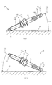
- (A) is a schematic diagram of the spark plug dropped from the front end side of the metal shell
- (b) is a schematic diagram of the spark plug dropped from the head of the terminal metal fitting. It is a result of a drop test.
- FIG. 1 is a one-side sectional view with an axis O as a boundary of a spark plug 10 according to an embodiment of the present invention.
- the lower side of the drawing is referred to as the front end side of the spark plug 10
- the upper side of the drawing is referred to as the rear end side of the spark plug 10.
- the spark plug 10 includes an insulator 11, a center electrode 20, a terminal fitting 30, and a metal shell 40. *
- the insulator 11 is a substantially cylindrical member formed of alumina or the like that is excellent in insulation at high temperatures and mechanical properties.
- the insulator 11 passes through the shaft hole 12 along the axis O.
- a step portion 13 that is reduced in diameter toward the distal end side is formed.
- the insulator 11 has a large-diameter portion 14 formed in the center in the direction of the axis O.
- the large diameter portion 14 is a portion having the largest outer diameter in the insulator 11.
- a small-diameter portion 15 having an outer diameter smaller than that of the large-diameter portion 14 is connected to the distal end side of the large-diameter portion 14.
- a distal end portion 16 having an outer diameter smaller than that of the small diameter portion 15 is connected to the distal end side of the small diameter portion 15.
- a locking portion 17 that is reduced in diameter toward the distal end side is formed on the outer periphery of the boundary between the distal end portion 16 and the small diameter portion 15.
- the step portion 13 is provided on the inner periphery of the small diameter portion 15.
- the center electrode 20 is a rod-shaped electrode that is inserted into the distal end side of the shaft hole 12 and is held by the insulator 11 along the axis O.
- the center electrode 20 is connected to a shaft portion 21 extending in the direction of the axis O and a head portion 22 projecting in a direction perpendicular to the shaft portion 21.
- the head portion 22 is locked to the step portion 13, and the shaft portion 21 is disposed in the shaft hole 12 with the tip protruding from the insulator 11.
- the center electrode 20 has a core material excellent in thermal conductivity embedded in the electrode base material.
- the electrode base material is made of an alloy mainly composed of Ni or a metal material made of Ni, and the core material is made of copper or an alloy mainly composed of copper. *
- the terminal fitting 30 is a rod-like member to which a high voltage cable (not shown) is connected, and is formed of a conductive metal material (for example, low carbon steel).
- the terminal fitting 30 includes a shaft portion 31 inserted into the shaft hole 12 and a protruding portion 34 that protrudes in the direction of the axis O with respect to the insulator 11.
- the outer diameter of the protruding portion 34 is larger than the outer diameter of the shaft portion 31.
- a fixing portion 32 that is close to the shaft hole 12 and a flange portion 33 that abuts against the end surface in the axial direction of the insulator 11 are formed between the protruding portion 34 and the shaft portion 31. Since the outer diameter of the shaft portion 31 is smaller than the outer diameter of the fixing portion 32, the terminal metal 30 has the fixing portion 32 in close contact with the shaft hole 12 of the insulator 11 and the flange portion 33 in close contact with the end surface of the insulator 11.
- a metal shell 40 is fixed to the front end side of the outer periphery of the insulator 11 with a space in the direction of the axis O from the protruding portion 34.
- the metal shell 40 is a substantially cylindrical member formed of a conductive metal material (for example, low carbon steel).
- the metal shell 40 has a front end 41 positioned on the outer side in the radial direction of the front end portion 16 of the insulator 11, and a rear end 42 in the radial direction of a portion of the insulator 11 on the rear end side relative to the large diameter portion 14.
- the metal shell 40 includes a body portion 43 surrounding the distal end portion 16 and the small diameter portion 15 of the insulator 11, a seat portion 46 having a distal end 47 connected to the rear end side of the body portion 43, and a rear end 48 of the seat portion 46.
- the connecting portion 49 is connected, the tool engaging portion 50 is connected to the connecting portion 49 at the front end 51, and the rear end portion 53 is connected to the rear end 52 of the tool engaging portion 50.
- the body portion 43 is formed with a male screw 44 that is screwed into a screw hole of an internal combustion engine (not shown) on the outer periphery, and a shelf portion 45 that locks the locking portion 17 of the insulator 11 from the front end side. It is formed around the circumference.
- a packing 54 is interposed between the shelf 45 and the locking portion 17.
- the packing 54 is an annular plate formed of a metal material such as a mild steel plate that is softer than the metal material constituting the metal shell 40.
- a male screw 44 having a nominal diameter of 8 mm is formed in the body portion 43. *
- the seat portion 46 is a portion for closing a gap between the screw hole of the internal combustion engine (not shown) and the male screw 44, and has an outer diameter larger than the outer diameter of the body portion 43.
- the seat portion 46 surrounds a boundary portion between the small diameter portion 15 and the large diameter portion 14.
- a gasket 56 is attached to the tip 47 of the seat 46.
- a gasket 56 sandwiched between the seat 46 and the internal combustion engine seals a gap between the male screw 44 and a screw hole (not shown).
- the outer diameter of the gasket 56 is smaller than the outer diameter of the seat 46.
- the connecting portion 49 is a part for plastically deforming (bending) and fixing by caulking when the metal shell 40 is assembled to the insulator 11.
- the connecting portion 49 surrounds the distal end side of the large diameter portion 14.
- the outer diameter of the connecting portion 49 is smaller than the outer diameter of the seat portion 46, and the thickness of the connecting portion 49 is thinner than the thickness of the seat portion 46 and the tool engaging portion 50.
- the tool engaging portion 50 is a portion that engages a tool such as a wrench when the screw 44 is tightened in a screw hole of an internal combustion engine (not shown).
- the tool engaging portion 50 surrounds a portion of the insulator 11 on the rear end side with respect to the large diameter portion 14 and a rear end side of the large diameter portion 14.
- the tool engaging portion 50 has a hexagonal outer shape, and the diagonal distance and the two-surface width of the tool engaging portion 50 are larger than the outer diameters of the seat portion 46 and the connecting portion 49. *
- the rear end portion 53 is bent toward the inner side in the radial direction, and is located on the rear end side with respect to the large diameter portion 14.
- the outer diameter of the rear end portion 53 is smaller than the two-surface width of the tool engaging portion 50. Since the diagonal distance and the two-surface width of the tool engaging portion 50 are larger than the outer diameters of the body portion 43 (male screw 44), the seat portion 46, the connecting portion 49, and the rear end portion 53, the tool engaging portion 50 is The overhanging portion that protrudes most outward in the radial direction of the metal shell 40 is configured. *
- the thickness of the thickest portion of the seat portion 46 in the direction perpendicular to the axis is thicker than the thickness of the thickest portion of the tool engagement portion 50 in the direction perpendicular to the axis.
- the thickness of the seat 46 and the tool engaging portion 50 is thicker than the thickness of the body 43.
- the thickness of the connecting portion 49 in the direction perpendicular to the axis is the same as the thickness of the rear end portion 53 in the direction perpendicular to the axis. *
- the external diameter of the external thread 4 is 8 mm, and the external diameter of the external thread 44 is smaller than the external diameter of the insulator 11 where the rear end 42 of the metal shell 40 surrounds.
- a filler 55 such as talc is disposed inside the tool engaging portion 50 and the rear end portion 53 in the radial direction, on the front end side of the rear end portion 53 and on the rear end side of the large diameter portion 14.
- a portion of the metal shell 40 from the rear end portion 53 to the locking portion 17 applies a load that presses the insulator 11 in the direction of the axis O to the large diameter portion 14 and the locking portion 17 via the filler 55.
- the metal shell 40 is fixed to the outer periphery of the insulator 11. Since the packing 54 and the filler 55 are compressed in the axial direction, airtightness can be ensured.
- the ground electrode 60 is a rod-shaped metal member (for example, a nickel-base alloy member) joined to the tip 41 of the metal shell 40.
- the tip of the ground electrode 60 is opposed to the center electrode 20 via a gap (spark gap). In the present embodiment, the ground electrode 60 is bent.
- a resistor 61 is disposed in the shaft hole 12 of the insulator 11 between the head portion 22 of the center electrode 20 and the shaft portion 31 of the terminal fitting 30.
- the conductive seal 62 electrically connects the head 22 and the resistor 61
- the conductive seal 63 electrically connects the resistor 61 and the shaft portion 31.
- the terminal fitting 30 is electrically connected to the center electrode 20 in the shaft hole 12.
- the mass of the insulator 11, the center electrode 20, the terminal fitting 30, the metal shell 40, and the like are such that the center of gravity 64 exists on the rear end side of the tip 51 of the tool engaging portion 50 (projecting portion). Are distributed in the direction of the axis O.
- a center of gravity 64 exists between the front end 51 of the tool engaging portion 50 and the rear end 42 of the metal shell 40, and in particular, between the front end 51 and the rear end 52 of the tool engaging portion 50. 64 exists.
- the metal shell 40 of the spark plug 10 has a length L in the axis O direction from the tip 51 (the boundary between the tip 51 and the connecting portion 49) of the tool engaging portion 50 to the tip 41 of the metal shell 40 is 33 mm or more. Is set. *
- the spark plug 10 is manufactured by the following method, for example. First, the center electrode 20 is inserted into the shaft hole 12 of the insulator 11 and disposed so that the tip of the shaft portion 21 is exposed to the outside from the shaft hole 12. Next, while the conductive seals 62 and 63 and the resistor 61 are formed in the shaft hole 12, the shaft portion 31 of the terminal fitting 30 is inserted into the shaft hole 12 and the fixing portion 32 is disposed in the shaft hole 12. Thereby, the terminal metal fitting 30 is fixed to the rear end of the insulator 11 while ensuring the conduction between the terminal metal fitting 30 and the center electrode 20.
- the insulator 11 is inserted into the metal shell 40 to which the ground electrode 60 is bonded in advance, the connecting portion 49 and the rear end portion 53 are bent, and the metal shell 40 is assembled to the insulator 11.
- the ground electrode 60 is bent so that the tip of the ground electrode 60 faces the center electrode 20, and the gasket 56 is attached to obtain the spark plug 10.
- FIG. 2A is a schematic diagram of the spark plug 10 that has fallen to the floor surface 65 from the tip 41 side of the metal shell 40
- FIG. 2B is a spark that has fallen to the floor surface 65 from the protruding portion 34 of the terminal fitting 30
- 1 is a schematic diagram of a plug 10.
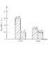
- FIG. FIG. 3 shows the result of the drop test. 2A and 2B indicates the angle between the axis O of the spark plug 10 and the floor surface 65 at the moment when the spark plug 10 first collides with the floor surface 65. + ⁇ (see FIG. 2A) indicates a collision from the tip 41 side of the metal shell 40, and ⁇ (see FIG. 2B) indicates a collision from the protruding portion 34 side of the terminal metal 30. *
- the spark plug 10 in which the center of gravity 64 exists on the rear end side with respect to the front end 51 of the tool engagement portion 50, the spark plug (FIG. (Not shown) is a comparative example. Also for the comparative example, the same reference numerals as those of the spark plug 10 are given and each part will be described. *
- the spark plug 10 collides with the floor surface 65 from the front end 41 side of the metal shell 40
- the front end 41 side of the metal shell 40 is elastically deformed by the impact, and the deformation is restored by the force.
- the tip 41 side of the metal fitting 40 rebounds, and the spark plug 10 rotates around the center of gravity 64 as a rotation axis.
- the protruding portion 34 of the terminal fitting 30 collides with the floor surface 65. Since the fixing part 32 (see FIG. 1) of the terminal fitting 30 is close to the shaft hole 12, the impact of the protrusion 34 colliding with the floor surface 65 is transmitted to the fixing part 32, and the fixing part 32 of the insulator 11 is Cracks are likely to occur in the adjacent end portions 66.
- the gap between the fixed portion 32 and the shaft hole 12 is 0.1 mm or less (the same applies to the comparative example). *
- the spark plug 10 since the spark plug 10 has the center of gravity 64 on the rear end side of the tip 51 of the tool engaging portion 50, the distance from the center of gravity 64 to the protruding portion 34 can be shortened as compared with the comparative example. Therefore, it is possible to reduce the rotational moment of the projecting portion 34 having the vicinity of the center of gravity 64 when the front end 41 side of the metallic shell 40 rebounds. As a result, the spark plug 10 can reduce the impact force when the projecting portion 34 collides with the floor surface 65 as compared with the comparative example. Therefore, the end portion 66 of the insulator 11 is cracked as compared with the comparative example. It can be difficult. *
- the protruding portion 34 of the terminal fitting 30 receives a drop impact. Since the impact force at this time depends on the mass of the spark plug 10 and the acceleration at the time of collision, the impact force is not significantly different between the spark plug 10 and the comparative example. The rate of occurrence of cracks due to this impact is compared to the rate of occurrence of cracks when the spark plug 10 collides against the floor surface 65 from the tip 41 side of the metal shell 40 when the spark plug 10 is dropped from the same height. Is extremely low (described later). *
- the protruding portion 34 of the terminal fitting 30 receives a drop impact
- the protruding portion 34 side rebounds and the spark plug 10 rotates about the center of gravity 64 around the rotation axis as described above.
- the tip 41 side of the metal shell 40 collides with the floor surface 65, but the insulator 11 is surrounded by the metal shell 40, so that the insulator 11 is not cracked. Since the impact at this time is quite small, almost no rebound on the tip 41 side of the metal shell 40 occurs.
- the spark plug 10 rolls in a state where the tool engaging portion 50 is in contact with the floor surface 65, and the protruding portion 34 hits the floor surface 65. At the impact at this time, the end 66 of the insulator 11 is not cracked.
- the diagonal distance and the two-surface width of the tool engaging portion 50 are larger than the outer diameter of the other part.
- the tool engaging portion 50 first collides with the floor surface 65.
- the tool engaging portion 50 is thicker than the thickness of the body portion 43, and the thickness of the large diameter portion 14 that the tool engaging portion 50 surrounds is thicker than the thickness of the insulator 11 other than the large diameter portion 14. Although it depends on the impact force received by 50, the insulator 11 including the large diameter portion 14 hardly cracks.
- FIG. 3 shows the result of a drop test in which the spark plug 10 is freely dropped from a height of 1 m and the spark plug 10 is made to collide with a metal surface plate (floor surface 65) whose upper surface is horizontally disposed.
- FIG. 3 shows the relationship between the occurrence rate (%) of cracks occurring in the insulator 11 and the angle ⁇ between the axis O of the spark plug 10 and the horizontal plane when free fall starts.
- the drop test was implemented about the spark plug 10 whose nominal diameter of the external thread 44 of the metal shell 40 is 14 mm, 12 mm, 10 mm, and 8 mm.
- FIG. 3 shows the result of a drop test of the spark plug 10 in which the nominal diameter of the male screw 44 is 8 mm. *
- the spark plug 10 is dropped when the protruding portion 34 side of the terminal fitting 30 is inclined downward than when it is dropped while the tip 41 side of the metallic shell 40 is inclined downward. It became clear that the incidence of cracking can be lowered. This is because the front end 41 side of the metal shell 40 that first collided with the surface plate bounces back, and the end portion 66 of the insulator 11 is cracked by the impact of the protruding portion 34 of the terminal metal fitting 30 colliding with the floor surface 65. *
- the spark plug 10 has a center of gravity 64 on the rear end side of the tip end 51 of the tool engaging portion 50 that protrudes most outward in the radial direction in the metal shell 40, so that the tip 41 side of the metal shell 40 is inclined downward. It is possible to make it difficult to change the aerial posture when falling. As a result, it is possible to make it easily collide with the floor surface 65 from the tool engaging portion 50 of the metallic shell 40 or the protruding portion 34 of the terminal fitting 30. As a result, the insulator 11 can be hardly cracked. *
- the center of gravity 64 exists between the tip 51 of the tool engaging portion 50 and the rear end 42 of the metal shell 40, the center of gravity 64 is closer to the rear end than the rear end 42 of the metal shell 40.
- the vicinity of the 40 tool engaging portions 50 can be easily collided with the floor surface 65 first. Since the vicinity of the tool engaging portion 50 of the metal shell 40 absorbs the impact of the collision, the insulator 11 can be made more difficult to break.
- the spark plug 10 since the center of gravity 64 of the spark plug 10 exists between the tip 51 of the tool engaging portion 50 and the rear end 52 of the tool engaging portion 50, the spark plug 10 has fallen from a state in which the axis O is substantially horizontal. In some cases, the probability that the vicinity of the tool engaging portion 50 of the metal shell 40 first collides with the floor surface 65 can be further increased. Therefore, the insulator 11 can be further hardly broken.
- the rate of occurrence of cracking when the tip 41 side of the metal shell 40 is tilted downward is such that the spark plug 10 having a length L of 33 mm is the spark plug 10 having a length L of 26 mm. About twice as much. Although not shown, the occurrence rate of cracks increased as the length L became longer than 33 mm. On the other hand, regardless of the length L, the rate of occurrence of cracks was almost the same when dropped with the protruding portion 34 side of the terminal fitting 30 tilted downward. *
- the tip 41 side of the metal shell 40 is placed on the floor surface 65 due to the influence of the rotational moment with the center of gravity 64 as the rotation axis when it collides with the floor surface 65 from the tip 41 side of the metal shell 40. It is surmised that the impact is likely to increase when the protrusion 34 of the terminal fitting 30 collides with the floor surface 65 after the collision. As a result, the end portion 66 of the insulator 11 is easily cracked. On the other hand, it is possible to make it difficult to collide from the front end 41 side of the metal shell 40 by making the center of gravity 64 exist on the rear end side of the front end 51 of the tool engaging portion 50. As a result, since the insulator 11 can be hardly broken even if the length L is 33 mm or more, the effect of suppressing the crack of the insulator 11 can be increased. *
- the protruding portion 34 of the terminal fitting 30 is formed integrally with the shaft portion 31
- the present invention is not necessarily limited thereto.
- the protruding portion 34 it is possible to make the protruding portion 34 a separate member from the shaft portion 31.
- a screw is provided on the shaft portion 31 and a female screw is provided on the protruding portion 34 and the protruding portion 34 is screwed to the shaft portion 31, or the protruding portion 34 is fixed to the shaft portion 31 so as not to be removed by caulking or the like.
- the present invention is not necessarily limited thereto.
- the tool engaging part 50 was the part (projected part) most projected on the radial direction outer side among the metal shells 40
- the seat portion 46 an overhang portion by making the outer diameter of the seat portion 46 larger than the diagonal distance of the tool engaging portion 50.
- the center of gravity 64 on the rear end side with respect to the front end 47 of the seat portion 46, it is possible to realize the same effect as that of the above embodiment.
- the length L refers to the length in the direction of the axis O from the tip 47 of the seat 46 to the tip 41 of the metal shell 40.
- the center of gravity 64 exists between the front end 47 of the seat 46 and the rear end 42 of the metal shell 40, the seat 46 can easily collide with the floor surface 65 first. Further, the presence of the center of gravity 64 from the front end 47 of the seat 46 to the rear end 48 of the seat 46 can further increase the probability that the seat 46 first collides with the floor surface 65. Therefore, similarly to the above embodiment, the insulator 11 can be hardly cracked.
- the tool engaging part 50 located in the back end side rather than the seat part 46 is an overhang
- the center of gravity 64 is present on the rear end side of the front end 51 of the tool engaging portion 50, the front end 41 side of the metal shell 40 is first located on the rear end side of the front end 47 of the seat 46. This is because it is possible to reduce the rotational moment of the projecting portion 34 with the vicinity of the center of gravity 64 when it hits the floor surface 65 and bounces off, so that it is difficult for the end portion 66 of the insulator 11 to crack.
- the ground electrode 60 joined to the metal shell 40 is bent has been described. However, it is not necessarily limited to this. Naturally, instead of using the bent ground electrode 60, it is possible to use a linear ground electrode 60. In this case, the front end side of the metal shell 40 is extended in the direction of the axis O, the linear ground electrode 60 is joined to the metal shell 40, and the front end portion of the ground electrode 60 is opposed to the center electrode 20. *
- the ground electrode 60 is arranged so that the tip of the ground electrode 60 and the center electrode 20 face each other on the axis O.
- the present invention is not necessarily limited to this, and the positional relationship between the ground electrode 60 and the center electrode 20 can be set as appropriate.
- Other positional relationships between the ground electrode 60 and the center electrode 20 include, for example, arranging the ground electrode 60 so that the side surface of the center electrode 20 and the tip of the ground electrode 60 face each other.
- ground electrode 60 is joined to the metal shell 40.
- present invention is not necessarily limited to this, and it is a matter of course that a plurality of ground electrodes 60 are joined to the metal shell 40. Is possible.
Landscapes
- Spark Plugs (AREA)
Abstract
落下時に絶縁体を割れ難くできるスパークプラグを提供すること。スパークプラグは、中心電極と、軸線に沿って貫通する軸孔の先端側に中心電極が配置される絶縁体と、軸孔に一部が挿入され絶縁体の後端に固定されると共に軸孔の内側で中心電極と電気的に接続される端子金具と、絶縁体が後端側から突出するように絶縁体を外周側から保持する筒状の主体金具と、を備え、主体金具のうち径方向の外側に最も張り出した張出部の先端よりも後端側に重心が存在する。
Description
本発明はスパークプラグに関し、特に絶縁体を割れ難くできるスパークプラグに関するものである。
内燃機関に装着されるスパークプラグとして、軸孔が形成された絶縁体と、絶縁体が後端側から突出するように絶縁体を外周側から保持する主体金具と、軸孔の先端側に配置された中心電極と、絶縁体の後端に配置されると共に軸孔の内側で中心電極と電気的に接続された端子金具と、を備えるものが知られている(例えば特許文献1)。絶縁体は脆性材料なので、内燃機関に装着するとき等にスパークプラグを落としてしまうと、落下の衝撃で絶縁体に割れが生じることがある。
しかしながら、絶縁体の割れは短絡の原因となるので、落下時に絶縁体を割れ難くしたいという要求がある。
本発明は上述した要求に応えるためになされたものであり、落下時に絶縁体を割れ難くできるスパークプラグを提供することを目的としている。
この目的を達成するために本発明のスパークプラグは、先端側から後端側へと軸線に沿って延びる中心電極と、軸線に沿って貫通する軸孔の先端側に中心電極が配置される絶縁体と、軸孔に一部が挿入され絶縁体の後端に固定されると共に軸孔の内側で中心電極と電気的に接続される端子金具と、絶縁体が後端側から突出するように絶縁体を外周側から保持する筒状の主体金具と、を備える。スパークプラグは、主体金具のうち径方向の外側に最も張り出した張出部の先端よりも後端側に重心が存在する。
請求項1記載のスパークプラグによれば、主体金具のうち径方向の外側に最も張り出した張出部の先端よりも後端側に重心が存在するので、軸線を略水平方向に向けた状態からスパークプラグが落下したときには、主体金具の張出部や端子金具から衝突させ易くできる。発明者は、スパークプラグが落下して主体金具の先端側が衝突した後、跳ね返って端子金具が衝突すると、端子金具に加わる衝撃によって、端子金具付近の絶縁体に割れが生じ易いことを見出した。これに基づき、張出部の先端よりも後端側に重心を存在させることにより、軸線を略水平方向に向けた状態からスパークプラグが落下したときに、主体金具の先端側を空中で下向きに傾かせ難くできる。その結果、確率的に、主体金具の先端側から衝突し難くできるので、落下時の主体金具の跳ね返りによる衝撃を端子金具に加わり難くできる。よって、絶縁体を割れ難くできる。
請求項2記載のスパークプラグによれば、重心は張出部の先端から主体金具の後端までの間に存在するので、重心が主体金具の後端よりも後端側に存在する場合に比べて、軸線を略水平方向に向けた状態からスパークプラグが落下したときに、主体金具の張出部付近を最初に衝突させ易くできる。主体金具の張出部付近が衝撃を吸収するので、請求項1の効果に加え、絶縁体をより割れ難くできる。
請求項3記載のスパークプラグによれば、重心は張出部の先端から張出部の後端までの間に存在するので、軸線を略水平方向に向けた状態からスパークプラグが落下したときに、主体金具の張出部付近が最初に衝突する確率をさらに高めることができる。よって、請求項2の効果に加え、絶縁体をさらに割れ難くできる。
請求項4記載のスパークプラグによれば、張出部は工具が係合する工具係合部なので、落下の衝撃で仮に張出部が変形しても、工具の係合に支障のない範囲であれば、工具係合部の機能を損なわないようにできる。よって、請求項1から3のいずれかの効果に加え、絶縁体に割れを生じ難くしつつ、機能的な悪影響を生じ難くできる。
請求項5記載のスパークプラグによれば、張出部の先端から主体金具の先端までの軸線方向の長さは33mm以上なので、主体金具の先端側から衝突した場合には、重心の付近を回転軸とする回転モーメントの影響によって、主体金具の先端側が最初に衝突した後、跳ね返って端子金具が衝突したときの衝撃が大きくなり易く、絶縁体に割れが生じ易い。これに対し、張出部の先端よりも後端側に重心を存在させることにより、主体金具の先端側から衝突させ難くし、絶縁体を割れ難くできるので、請求項1から4のいずれかの効果に加え、絶縁体の割れを抑制する効果を大きくできる。
以下、本発明の好ましい実施形態について添付図面を参照して説明する。図1は本発明の一実施の形態におけるスパークプラグ10の軸線Oを境にした片側断面図である。図1では、紙面下側をスパークプラグ10の先端側、紙面上側をスパークプラグ10の後端側という。図1に示すようにスパークプラグ10は、絶縁体11、中心電極20、端子金具30及び主体金具40を備えている。
絶縁体11は、高温下の絶縁性や機械的特性に優れるアルミナ等により形成された略円筒状の部材である。絶縁体11は、軸線Oに沿って軸孔12が貫通する。軸孔12の先端側には、先端側に向かって縮径する段部13が形成されている。絶縁体11は、軸線O方向の中央に大径部14が形成されている。大径部14は、絶縁体11のうち外径が最も大きい部分である。大径部14の先端側に、大径部14よりも外径の小さい小径部15が連接されている。小径部15の先端側に、小径部15よりも外径の小さい先端部16が連接されている。先端部16と小径部15との境界の外周に、先端側に向かって縮径する係止部17が形成されている。段部13は小径部15の内周に設けられている。
中心電極20は、軸孔12の先端側に挿入され軸線Oに沿って絶縁体11に保持される棒状の電極である。中心電極20は、軸線O方向に延びる軸部21と、軸部21に対して軸直角方向へ張り出す頭部22と、が連接されている。頭部22は段部13に係止され、軸部21は先端を絶縁体11から突出させて軸孔12に配置されている。中心電極20は、熱伝導性に優れる芯材が電極母材に埋設されている。電極母材は、Niを主体とする合金またはNiからなる金属材料で形成されており、芯材は銅または銅を主成分とする合金で形成されている。
端子金具30は、高圧ケーブル(図示せず)が接続される棒状の部材であり、導電性を有する金属材料(例えば低炭素鋼等)によって形成されている。端子金具30は、軸孔12に挿入される軸部31と、絶縁体11に対して軸線O方向へ突出する突出部34とを備えている。本実施の形態では、突出部34の外径は軸部31の外径よりも大きい。
端子金具30は、突出部34と軸部31との間に、軸孔12に近接する固定部32、及び、絶縁体11の軸方向の端面に突き当てられる鍔部33が形成されている。軸部31の外径は固定部32の外径より小さいので、端子金具30は固定部32が絶縁体11の軸孔12に密着し、鍔部33が絶縁体11の端面に密着する。絶縁体11の外周の先端側に、突出部34と軸線O方向に間隔をあけて主体金具40が固定されている。
主体金具40は、導電性を有する金属材料(例えば低炭素鋼等)によって形成された略円筒状の部材である。主体金具40は、先端41が、絶縁体11の先端部16の径方向の外側に位置し、後端42が、絶縁体11のうち大径部14よりも後端側の部分の径方向の外側に位置する。主体金具40は、絶縁体11の先端部16及び小径部15を取り囲む胴部43と、胴部43の後端側に先端47が連接される座部46と、座部46の後端48に連接される接続部49と、接続部49に先端51が連接される工具係合部50と、工具係合部50の後端52に連接される後端部53と、を備えている。
胴部43は、内燃機関(図示せず)のねじ穴に螺合するおねじ44が外周に形成されており、絶縁体11の係止部17を先端側から係止する棚部45が内周に形成されている。棚部45と係止部17との間にパッキン54が介在する。パッキン54は、主体金具40を構成する金属材料よりも軟質の軟鋼板等の金属材料で形成される円環状の板材である。本実施の形態では、呼び径が8mmのおねじ44が胴部43に形成されている。
座部46は、内燃機関(図示せず)のねじ穴とおねじ44との隙間を塞ぐための部位であり、胴部43の外径よりも外径が大きく形成されている。座部46は、小径部15と大径部14との境界部を取り囲む。本実施の形態では、座部46の先端47にガスケット56が装着されている。座部46と内燃機関との間に挟まれたガスケット56は、おねじ44とねじ穴(図示せず)との隙間を封止する。ガスケット56の外径は、座部46の外径より小さい。
接続部49は、主体金具40を絶縁体11に組み付けるときに、塑性変形(屈曲)させて加締め固定するための部位である。接続部49は大径部14の先端側を取り囲む。接続部49の外径は、座部46の外径よりも小さく、接続部49の肉厚は、座部46及び工具係合部50の肉厚よりも薄い。
工具係合部50は、内燃機関(図示せず)のねじ穴におねじ44を締め付けるときに、レンチ等の工具を係合させる部位である。工具係合部50は、絶縁体11のうち大径部14よりも後端側の部分および大径部14の後端側を取り囲む。本実施の形態では、工具係合部50は外形が六角形であり、工具係合部50の対角距離および二面幅は、座部46及び接続部49の外径よりも大きい。
後端部53は径方向の内側へ向けて屈曲し、大径部14よりも後端側に位置する。後端部53の外径は、工具係合部50の二面幅より小さい。工具係合部50の対角距離および二面幅は、胴部43(おねじ44)、座部46、接続部49及び後端部53の外径よりも大きいので、工具係合部50は、主体金具40のうち径方向の外側に最も張り出した張出部を構成する。
なお、座部46のうち最も厚い部分の軸直角方向における肉厚は、工具係合部50のうち最も厚い部分の軸直角方向における肉厚よりも厚い。座部46及び工具係合部50のこれらの肉厚は、胴部43の肉厚より厚い。接続部49の軸直角方向の肉厚と、後端部53の軸直角方向の肉厚とは同一である。
また、おねじ4は呼び径が8mmであり、おねじ44の外径は、絶縁体11のうち主体金具40の後端42が取り囲む位置の外径よりも小さい。これにより、主体金具40の胴部43の質量を小さくし、絶縁体11の後端側の質量を大きくすることができる。その結果、工具係合部50の先端51よりも後端側に重心64が存在するように調整し易くできる。
工具係合部50及び後端部53の径方向の内側であって、後端部53の先端側、且つ、大径部14の後端側に、タルク等の充填材55が配置される。主体金具40のうち後端部53から係止部17までの部分は、絶縁体11を軸線O方向に押圧する荷重を、充填材55を介して大径部14及び係止部17に加える。その結果、絶縁体11の外周に主体金具40が固定される。パッキン54及び充填材55が軸方向に圧縮されるので、気密を確保できる。
接地電極60は、主体金具40の先端41に接合される棒状の金属製(例えばニッケル基合金製)の部材である。接地電極60は、先端部が、中心電極20と間隙(火花ギャップ)を介して対向する。本実施の形態では、接地電極60は屈曲されている。
絶縁体11の軸孔12には、中心電極20の頭部22と端子金具30の軸部31との間に抵抗体61が配置されている。導電性シール62は頭部22と抵抗体61とを電気的に接続
し、導電性シール63は抵抗体61と軸部31とを電気的に接続する。これにより、端子金具30は軸孔12内で中心電極20と電気的に接続される。
し、導電性シール63は抵抗体61と軸部31とを電気的に接続する。これにより、端子金具30は軸孔12内で中心電極20と電気的に接続される。
スパークプラグ10は、工具係合部50(張出部)の先端51よりも後端側に重心64が存在するように、絶縁体11、中心電極20、端子金具30及び主体金具40等の質量が軸線O方向に配分されている。本実施の形態では、工具係合部50の先端51から主体金具40の後端42までの間に重心64が存在し、特に工具係合部50の先端51から後端52までの間に重心64が存在する。また、スパークプラグ10の主体金具40は、工具係合部50の先端51(先端51と接続部49との境界)から主体金具40の先端41までの軸線O方向の長さLが33mm以上に設定されている。
スパークプラグ10は、例えば、以下のような方法によって製造される。まず、中心電極20を絶縁体11の軸孔12に挿入し、軸部21の先端が軸孔12から外部に露出するように配置する。次いで、導電性シール62,63及び抵抗体61を軸孔12に形成しつつ、端子金具30の軸部31を軸孔12に挿入して固定部32を軸孔12内に配置する。これにより、端子金具30と中心電極20との導通を確保しつつ、端子金具30を絶縁体11の後端に固定する。次に、接地電極60が予め接合された主体金具40に絶縁体11を挿入し、接続部49及び後端部53を屈曲して主体金具40を絶縁体11に組み付ける。次いで、接地電極60の先端部が中心電極20と対向するように接地電極60を曲げ加工し、ガスケット56を装着してスパークプラグ10を得る。
内燃機関(図示せず)にスパークプラグ10を装着するときに、床面や地面など(以下「床面」と称す)にスパークプラグ10を落としてしまうと、落下の衝撃で、スパークプラグ10の絶縁体11に割れが生じることがある。発明者は、スパークプラグ10を床面65に落としたときに最初に床面65に衝突する位置と絶縁体11に生じる割れとの間に関係があることを見出した。以下、図2及び図3を参照して説明する。
図2(a)は主体金具40の先端41側から床面65に落下したスパークプラグ10の模式図であり、図2(b)は端子金具30の突出部34から床面65に落下したスパークプラグ10の模式図である。図3は落下試験の結果である。図2(a)及び図2(b)のθは、床面65にスパークプラグ10が最初に衝突した瞬間のスパークプラグ10の軸線Oと床面65との角度を示す。+θ(図2(a)参照)は主体金具40の先端41側から衝突したことを示し、-θ(図2(b)参照)は端子金具30の突出部34側から衝突したことを示す。
なお、工具係合部50の先端51よりも後端側に重心64が存在するスパークプラグ10に対して、工具係合部50の先端51よりも先端側に重心64が存在するスパークプラグ(図示せず)を比較例とする。比較例についても、スパークプラグ10と同一の符号を付して各部を説明する。
図2(a)に示すように、主体金具40の先端41側からスパークプラグ10が床面65に衝突すると、その衝撃で主体金具40の先端41側が弾性変形し、変形が復元する力で主体金具40の先端41側が跳ね返り、重心64付近を回転軸としてスパークプラグ10が回転する。その結果、端子金具30の突出部34が床面65に衝突する。端子金具30は固定部32(図1参照)が軸孔12に近接しているので、突出部34が床面65に衝突した衝撃が固定部32に伝わり、絶縁体11のうち固定部32が近接した端部66に割れが生じ易い。なお、本実施の形態では、固定部32と軸孔12との隙間は0.1mm以下である(比較例においても同じ)。
しかし、スパークプラグ10は工具係合部50の先端51よりも後端側に重心64が存在するので、比較例に比べて、重心64から突出部34までの距離を短くできる。よって、主体金具40の先端41側が跳ね返るときの重心64付近を回転軸とする突出部34の回転モーメントを小さくできる。その結果、スパークプラグ10は、突出部34が床面65に衝突したときの衝撃力を比較例に比べて小さくできるので、比較例に比べて、絶縁体11の端部66の割れを発生し難くできる。
図2(b)に示すように、端子金具30の突出部34側からスパークプラグ10が床面65に衝突すると、端子金具30の突出部34が落下の衝撃を受ける。このときの衝撃力はスパークプラグ10の質量および衝突時の加速度に依存するので、その衝撃力はスパークプラグ10と比較例との間に大差はない。なお、この衝撃による割れの発生率は、スパークプラグ10を同じ高さから落とした場合に、主体金具40の先端41側からスパークプラグ10が床面65に衝突したときの割れの発生率に比べて著しく低い(後述する)。
また、端子金具30の突出部34が落下の衝撃を受けると、上記と同様に、突出部34側が跳ね返り、重心64付近を回転軸としてスパークプラグ10が回転する。その結果、主体金具40の先端41側が床面65に衝突するが、絶縁体11は主体金具40に取り囲まれているので、絶縁体11に割れは生じない。このときの衝撃はかなり小さいので、主体金具40の先端41側の跳ね返りはほとんど生じない。その結果、スパークプラグ10は、工具係合部50が床面65に接触した状態で転がり、突出部34が床面65に当たる。このときの衝撃では絶縁体11の端部66に割れは生じない。
なお、スパークプラグ10が、軸線Oを略水平方向に向けた状態で床面65に落下すると、工具係合部50の対角距離および二面幅が他の部分の外径よりも大きいので、工具係合部50が床面65に最初に衝突する。工具係合部50は胴部43の肉厚より厚く、工具係合部50が取り囲む大径部14の肉厚は大径部14以外の絶縁体11の肉厚より厚いので、工具係合部50が受ける衝撃力にもよるが、大径部14を含む絶縁体11に割れはほとんど生じない。
図3は、1mの高さからスパークプラグ10を自由落下させて、上面が水平に配置された金属製の定盤(床面65)にスパークプラグ10を衝突させた落下試験の結果である。図3には、絶縁体11に生じる割れの発生率(%)と、自由落下を始めるときのスパークプラグ10の軸線Oと水平面との角度θと、の関係が図示されている。なお、落下試験は、主体金具40のおねじ44の呼び径が14mm,12mm,10mm,8mmのスパークプラグ10について実施した。図3は、おねじ44の呼び径が8mmのスパークプラグ10の落下試験の結果が図示されている。
図3において、θ=+25°は、自由落下を始めるときのスパークプラグ10の姿勢が、主体金具40の先端41側が水平面に対して下に25°傾いていたことを示し、θ=-25°は、自由落下を始めるときの姿勢が、端子金具30の突出部34側が水平面に対して下に25°傾いていたことを示す。スパークプラグ10は軸線O方向の略中心に重心64があるので、定盤に衝突するときのスパークプラグ10の姿勢は、自由落下を始めるときのスパークプラグ10の姿勢とほぼ同じであった。
図3に示すように、工具係合部50の先端51から主体金具40の先端41までの軸線O方向の長さLが33mmのスパークプラグ10では、θ=+25°における発生率が60%なのに対し、θ=-25°における発生率は20%であった。また、長さLが26mmのスパークプラグ10では、θ=+25°における発生率が30%なのに対し、θ=-25°における発生率は20%であった。
スパークプラグ10は、長さLに関わらず、端子金具30の突出部34側が下に傾いた状態で落下したときの方が、主体金具40の先端41側が下に傾いた状態で落下したときより、割れの発生率を低くできることが明らかになった。これは、定盤に最初に衝突した主体金具40の先端41側が跳ね返り、端子金具30の突出部34が床面65に衝突した衝撃によって絶縁体11の端部66に割れが生じることによる。
スパークプラグ10は、主体金具40のうち径方向の外側に最も張り出した工具係合部50の先端51よりも後端側に重心64が存在するので、主体金具40の先端41側が下に傾くように落下時の空中姿勢を変化させ難くすることができる。その結果、確率的に、主体金具40の工具係合部50や端子金具30の突出部34から床面65に衝突させ易くできる。その結果、絶縁体11に割れを生じ難くできる。
なお、スパークプラグ10は、重心64が工具係合部50の先端51から主体金具40の後端42までの間に存在するので、重心64が主体金具40の後端42よりも後端側に存在する場合(主体金具40から後端側へ突出した絶縁体11の内部に重心64が存在する場合)に比べて、軸線Oが略水平の状態からスパークプラグ10が落下したときに、主体金具40の工具係合部50付近を最初に床面65に衝突させ易くできる。主体金具40の工具係合部50付近が衝突の衝撃を吸収するので、絶縁体11をより割れ難くできる。
特にスパークプラグ10は、重心64が、工具係合部50の先端51から工具係合部50の後端52までの間に存在するので、軸線Oが略水平の状態からスパークプラグ10が落下したときに、主体金具40の工具係合部50付近が最初に床面65に衝突する確率をさらに高めることができる。よって、絶縁体11をさらに割れ難くできる。
主体金具40のうち径方向の外側に最も張り出した工具係合部50が、落下の衝撃で仮に変形しても、工具の係合に支障のない範囲であれば、工具係合部50の機能を損なわないようにできる。よって、絶縁体11に割れを生じ難くしつつ、機能的な悪影響を生じ難くできる。
図3に示すように、主体金具40の先端41側が下に傾いた状態で落下したときの割れの発生率は、長さLが33mmのスパークプラグ10が、長さLが26mmのスパークプラグ10の約2倍であった。図示してないが、割れの発生率は、長さLが33mmより長くなるにつれて増加した。一方、端子金具30の突出部34側が下に傾いた状態で落下したときの割れの発生率は、長さLに関わらず、ほぼ同じであった。
長さLが33mm以上であると、主体金具40の先端41側から床面65に衝突した場合に、重心64を回転軸とする回転モーメントの影響によって、主体金具40の先端41側が床面65に衝突した後、跳ね返って端子金具30の突出部34が床面65に衝突したときの衝撃が大きくなり易いと推察される。その結果、絶縁体11の端部66に割れが生じ易くなる。これに対し、工具係合部50の先端51よりも後端側に重心64を存在させることにより、主体金具40の先端41側から衝突させ難くできる。その結果、長さLが33mm以上のスパークプラグ10であっても絶縁体11を割れ難くできるので、絶縁体11の割れを抑制する効果を大きくできる。
以上、実施の形態に基づき本発明を説明したが、本発明は上記実施の形態に何ら限定されるものではなく、本発明の趣旨を逸脱しない範囲内で種々の改良変形が可能であることは容易に推察できるものである。
上記実施の形態では、端子金具30の突出部34が軸部31と一体に形成された場合について説明したが、必ずしもこれに限られるものではない。突出部34を軸部31と別の部材にすることは当然可能である。例えば、軸部31におねじを設け突出部34にめねじを設けて軸部31に突出部34を螺合するもの、加締め等によって軸部31に突出部34を取り外し不能に固定するものが挙げられる。なお、端子金具30の鍔部33を省略することは当然可能である。
上記実施の形態では、端子金具30の突出部34の外径が軸部31の外径よりも大きい場合について説明したが、必ずしもこれに限られるものではない。突出部34の外径を軸部31の外径以下にすることは当然可能である。その場合に、突出部34の外周に溝やね
じ等を形成することは当然可能である。
じ等を形成することは当然可能である。
上記実施の形態では、工具係合部50が、主体金具40のうち径方向の外側に最も張り出した部分(張出部)の場合について説明したが、必ずしもこれに限られるものではない。工具係合部50の対角距離よりも座部46の外径を大きくすることにより、座部46を張出部とすることは当然可能である。その場合には、座部46の先端47よりも後端側に重心64を存在させることにより、上記実施の形態と同様の作用効果を実現できる。この場合、長さLは、座部46の先端47から主体金具40の先端41までの軸線O方向の長さをいう。
さらに、座部46の先端47から主体金具40の後端42までの間に重心64を存在させることにより、座部46を最初に床面65に衝突させ易くできる。また、座部46の先端47から座部46の後端48までの重心64を存在させることにより、座部46を最初に床面65に衝突する確率をさらに高めることができる。よって、上記実施の形態と同様に、絶縁体11に割れを生じ難くできる。
なお、工具係合部50の対角距離と座部46の外径とが同じ大きさの場合には、座部46よりも後端側に位置する工具係合部50が張出部である。工具係合部50の先端51よりも後端側に重心64が存在する方が、座部46の先端47よりも後端側に重心64が存在するより、主体金具40の先端41側が最初に床面65に衝突して、跳ね返るときの重心64付近を回転軸とする突出部34の回転モーメントを小さくできるので、絶縁体11の端部66に割れを生じ難くできるからである。
上記実施の形態では説明を省略したが、耐火花消耗性を向上させるため、貴金属を含有するチップを中心電極20や接地電極60に設けることは当然可能である。
上記実施の形態では、抵抗体61を挟んで導電性シール62,63によって中心電極20と端子金具30とを電気的に接続する場合について説明したが、必ずしもこれに限られるものではない。抵抗体61を省略することは当然可能である。
上記実施の形態では、主体金具40に接合された接地電極60を屈曲させる場合について説明した。しかし、必ずしもこれに限られるものではない。屈曲した接地電極60を用いる代わりに、直線状の接地電極60を用いることは当然可能である。この場合には、主体金具40の先端側を軸線O方向に延ばし、直線状の接地電極60を主体金具40に接合して、接地電極60の先端部を中心電極20と対向させる。
上記実施の形態では、接地電極60の先端部と中心電極20とを軸線O上で対向するように接地電極60を配置する場合について説明した。しかし、必ずしもこれに限られるものではなく、接地電極60と中心電極20との位置関係は適宜設定できる。接地電極60と中心電極20との他の位置関係としては、例えば、中心電極20の側面と接地電極60の先端部とが対向するように接地電極60を配置すること等が挙げられる。
上記実施の形態では、主体金具40に接地電極60が1本接合された場合について説明したが、必ずしもこれに限られるものではなく、接地電極60を複数本、主体金具40に接合することは当然可能である。
10 スパークプラグ 11 絶縁体 12 軸孔 20 中心電極 30 端子金具 40 主体金具 41 先端 42 後端 50 工具係合部(張出部) 51 先端 52 後端 64 重心 L 長さ O 軸線
Claims (5)
- 先端側から後端側へと軸線に沿って延びる中心電極と、
前記軸線に沿って貫通する軸孔の先端側に前記中心電極が配置される絶縁体と、
前記軸孔に一部が挿入され前記絶縁体の後端に固定されると共に前記軸孔の内側で前記中心電極と電気的に接続される端子金具と、
前記絶縁体が後端側から突出するように前記絶縁体を外周側から保持する筒状の主体金具と、を備えるスパークプラグであって、
前記主体金具のうち径方向の外側に最も張り出した張出部の先端よりも後端側に重心が存在するスパークプラグ。
- 前記重心は、前記張出部の前記先端から前記主体金具の後端までの間に存在する請求項1記載のスパークプラグ。
- 前記重心は、前記張出部の前記先端から前記張出部の後端までの間に存在する請求項2に記載のスパークプラグ。
- 前記張出部は、工具が係合する工具係合部である請求項1から3のいずれかに記載のスパークプラグ。
- 前記張出部の前記先端から前記主体金具の先端までの軸線方向の長さは33mm以上である請求項1から4のいずれかに記載のスパークプラグ。
Priority Applications (1)
| Application Number | Priority Date | Filing Date | Title |
|---|---|---|---|
| DE112017007518.1T DE112017007518B4 (de) | 2017-05-11 | 2017-12-21 | Zündkerze |
Applications Claiming Priority (2)
| Application Number | Priority Date | Filing Date | Title |
|---|---|---|---|
| JP2017-094515 | 2017-05-11 | ||
| JP2017094515A JP6328296B1 (ja) | 2017-05-11 | 2017-05-11 | スパークプラグ |
Publications (1)
| Publication Number | Publication Date |
|---|---|
| WO2018207401A1 true WO2018207401A1 (ja) | 2018-11-15 |
Family
ID=62186701
Family Applications (1)
| Application Number | Title | Priority Date | Filing Date |
|---|---|---|---|
| PCT/JP2017/046009 Ceased WO2018207401A1 (ja) | 2017-05-11 | 2017-12-21 | スパークプラグ |
Country Status (3)
| Country | Link |
|---|---|
| JP (1) | JP6328296B1 (ja) |
| DE (1) | DE112017007518B4 (ja) |
| WO (1) | WO2018207401A1 (ja) |
Citations (2)
| Publication number | Priority date | Publication date | Assignee | Title |
|---|---|---|---|---|
| JPS63160691U (ja) * | 1987-04-08 | 1988-10-20 | ||
| JPH11242979A (ja) * | 1997-12-27 | 1999-09-07 | Denso Corp | 内燃機関用のスパークプラグ |
Family Cites Families (3)
| Publication number | Priority date | Publication date | Assignee | Title |
|---|---|---|---|---|
| EP0984463B1 (en) | 1997-05-23 | 2003-03-19 | Hitachi, Ltd. | Ignition coil unit for engine and engine provided with plastic head cover |
| JP5715212B2 (ja) | 2012-10-01 | 2015-05-07 | 日本特殊陶業株式会社 | 点火プラグ |
| JP6565344B2 (ja) | 2015-06-02 | 2019-08-28 | 株式会社デンソー | 内燃機関用のスパークプラグ及びその製造方法 |
-
2017
- 2017-05-11 JP JP2017094515A patent/JP6328296B1/ja active Active
- 2017-12-21 DE DE112017007518.1T patent/DE112017007518B4/de active Active
- 2017-12-21 WO PCT/JP2017/046009 patent/WO2018207401A1/ja not_active Ceased
Patent Citations (2)
| Publication number | Priority date | Publication date | Assignee | Title |
|---|---|---|---|---|
| JPS63160691U (ja) * | 1987-04-08 | 1988-10-20 | ||
| JPH11242979A (ja) * | 1997-12-27 | 1999-09-07 | Denso Corp | 内燃機関用のスパークプラグ |
Also Published As
| Publication number | Publication date |
|---|---|
| DE112017007518B4 (de) | 2024-09-12 |
| DE112017007518T5 (de) | 2020-01-23 |
| JP6328296B1 (ja) | 2018-05-23 |
| JP2018190672A (ja) | 2018-11-29 |
Similar Documents
| Publication | Publication Date | Title |
|---|---|---|
| KR101397776B1 (ko) | 스파크 플러그 | |
| JP5476360B2 (ja) | 点火プラグ | |
| CN102484006B (zh) | 火花塞 | |
| KR101665900B1 (ko) | 점화 플러그 | |
| CN104782006B (zh) | 火花塞 | |
| JP6328296B1 (ja) | スパークプラグ | |
| JP2015225774A (ja) | 金具、スパークプラグ、センサ | |
| US8912715B2 (en) | Spark plug | |
| CN103703638B (zh) | 火花塞 | |
| JP6741717B2 (ja) | スパークプラグ | |
| US9742157B2 (en) | Spark plug | |
| JP2013131375A (ja) | 点火プラグ | |
| US8674592B2 (en) | Spark plug having a crimp portion in the metal shell to firmly engage with the ceramic insulator | |
| JP6157519B2 (ja) | スパークプラグ | |
| JP6903717B2 (ja) | 点火プラグ | |
| JP2006012464A (ja) | スパークプラグおよびそれを備えた内燃機関 | |
| JP7076413B2 (ja) | スパークプラグ | |
| CN109412023B (zh) | 火花塞 | |
| JP2013254670A (ja) | スパークプラグ | |
| JPWO2019069640A1 (ja) | 点火プラグ | |
| JP2019029325A (ja) | 点火プラグ |
Legal Events
| Date | Code | Title | Description |
|---|---|---|---|
| 121 | Ep: the epo has been informed by wipo that ep was designated in this application |
Ref document number: 17909090 Country of ref document: EP Kind code of ref document: A1 |
|
| 122 | Ep: pct application non-entry in european phase |
Ref document number: 17909090 Country of ref document: EP Kind code of ref document: A1 |