WO2018207241A1 - スクリューコンベア - Google Patents
スクリューコンベア Download PDFInfo
- Publication number
- WO2018207241A1 WO2018207241A1 PCT/JP2017/017408 JP2017017408W WO2018207241A1 WO 2018207241 A1 WO2018207241 A1 WO 2018207241A1 JP 2017017408 W JP2017017408 W JP 2017017408W WO 2018207241 A1 WO2018207241 A1 WO 2018207241A1
- Authority
- WO
- WIPO (PCT)
- Prior art keywords
- screw
- delivery pipe
- chips
- storage tank
- screw conveyor
- Prior art date
- Legal status (The legal status is an assumption and is not a legal conclusion. Google has not performed a legal analysis and makes no representation as to the accuracy of the status listed.)
- Ceased
Links
Images





Classifications
-
- B—PERFORMING OPERATIONS; TRANSPORTING
- B65—CONVEYING; PACKING; STORING; HANDLING THIN OR FILAMENTARY MATERIAL
- B65G—TRANSPORT OR STORAGE DEVICES, e.g. CONVEYORS FOR LOADING OR TIPPING, SHOP CONVEYOR SYSTEMS OR PNEUMATIC TUBE CONVEYORS
- B65G33/00—Screw or rotary spiral conveyors
- B65G33/24—Details
- B65G33/32—Adaptations of bearings or couplings for supporting and connecting screws
-
- B—PERFORMING OPERATIONS; TRANSPORTING
- B23—MACHINE TOOLS; METAL-WORKING NOT OTHERWISE PROVIDED FOR
- B23Q—DETAILS, COMPONENTS, OR ACCESSORIES FOR MACHINE TOOLS, e.g. ARRANGEMENTS FOR COPYING OR CONTROLLING; MACHINE TOOLS IN GENERAL CHARACTERISED BY THE CONSTRUCTION OF PARTICULAR DETAILS OR COMPONENTS; COMBINATIONS OR ASSOCIATIONS OF METAL-WORKING MACHINES, NOT DIRECTED TO A PARTICULAR RESULT
- B23Q11/00—Accessories fitted to machine tools for keeping tools or parts of the machine in good working condition or for cooling work; Safety devices specially combined with or arranged in, or specially adapted for use in connection with, machine tools
-
- B—PERFORMING OPERATIONS; TRANSPORTING
- B23—MACHINE TOOLS; METAL-WORKING NOT OTHERWISE PROVIDED FOR
- B23Q—DETAILS, COMPONENTS, OR ACCESSORIES FOR MACHINE TOOLS, e.g. ARRANGEMENTS FOR COPYING OR CONTROLLING; MACHINE TOOLS IN GENERAL CHARACTERISED BY THE CONSTRUCTION OF PARTICULAR DETAILS OR COMPONENTS; COMBINATIONS OR ASSOCIATIONS OF METAL-WORKING MACHINES, NOT DIRECTED TO A PARTICULAR RESULT
- B23Q11/00—Accessories fitted to machine tools for keeping tools or parts of the machine in good working condition or for cooling work; Safety devices specially combined with or arranged in, or specially adapted for use in connection with, machine tools
- B23Q11/0042—Devices for removing chips
- B23Q11/0057—Devices for removing chips outside the working area
-
- B—PERFORMING OPERATIONS; TRANSPORTING
- B23—MACHINE TOOLS; METAL-WORKING NOT OTHERWISE PROVIDED FOR
- B23Q—DETAILS, COMPONENTS, OR ACCESSORIES FOR MACHINE TOOLS, e.g. ARRANGEMENTS FOR COPYING OR CONTROLLING; MACHINE TOOLS IN GENERAL CHARACTERISED BY THE CONSTRUCTION OF PARTICULAR DETAILS OR COMPONENTS; COMBINATIONS OR ASSOCIATIONS OF METAL-WORKING MACHINES, NOT DIRECTED TO A PARTICULAR RESULT
- B23Q11/00—Accessories fitted to machine tools for keeping tools or parts of the machine in good working condition or for cooling work; Safety devices specially combined with or arranged in, or specially adapted for use in connection with, machine tools
- B23Q11/0042—Devices for removing chips
- B23Q11/0067—Devices for removing chips chip containers located under a machine or under a chip conveyor
-
- B—PERFORMING OPERATIONS; TRANSPORTING
- B65—CONVEYING; PACKING; STORING; HANDLING THIN OR FILAMENTARY MATERIAL
- B65G—TRANSPORT OR STORAGE DEVICES, e.g. CONVEYORS FOR LOADING OR TIPPING, SHOP CONVEYOR SYSTEMS OR PNEUMATIC TUBE CONVEYORS
- B65G33/00—Screw or rotary spiral conveyors
- B65G33/08—Screw or rotary spiral conveyors for fluent solid materials
- B65G33/10—Screw or rotary spiral conveyors for fluent solid materials with non-enclosed screws
-
- B—PERFORMING OPERATIONS; TRANSPORTING
- B65—CONVEYING; PACKING; STORING; HANDLING THIN OR FILAMENTARY MATERIAL
- B65G—TRANSPORT OR STORAGE DEVICES, e.g. CONVEYORS FOR LOADING OR TIPPING, SHOP CONVEYOR SYSTEMS OR PNEUMATIC TUBE CONVEYORS
- B65G33/00—Screw or rotary spiral conveyors
- B65G33/08—Screw or rotary spiral conveyors for fluent solid materials
- B65G33/14—Screw or rotary spiral conveyors for fluent solid materials comprising a screw or screws enclosed in a tubular housing
Definitions
- the present invention relates to a screw conveyor for discharging chips to the outside.
- a discharge conveyor is provided for discharging the chips from the processing unit to the outside of the machine tool.
- a storage tank provided with an input port for receiving chips and coolant under the processing part is arranged, and the chips are sent backward in the storage tank. Then, the chips are sent to a discharge portion that extends further inclined upward, and the chips discharged therefrom are collected in a collection box.
- Such discharge conveyors include various types of conveyors such as a chip conveyor using a hinge belt, a drum conveyor, or a screw conveyor. Under such circumstances, the following Patent Document 1 discloses a screw conveyor.
- the conventional screw conveyor in this document has a screw having a spiral blade formed on the outer periphery of a rotating shaft, and the screw is rotatably supported via a bearing and inserted into a casing. As the screw rotates in the casing, chips discharged from the machine tool are pushed backward by the spiral blades.
- a discharge pipe is connected to the rear side of the discharge pipe. In this conventional example, the discharge pipe is formed so that its diameter increases toward the downstream side, and the conveyance resistance is reduced at the outlet portion where chips are sent out. Has been.
- the screw conveyor of the conventional example has a configuration for reducing the conveyance resistance so that the chips do not clog in the conveyance path as described above. Specifically, the diameter of the discharge pipe is increased, but the chips cause clogging in the casing of the screw conveyor, that is, the delivery pipe.
- a storage box for increasing the volume of the transport path is formed in the downstream portion of the delivery pipe so as to cope with a case where the amount of generated chips varies greatly.
- such a storage box or the like cannot be provided unless it has a structure that allows a sufficient installation space above.
- some screw conveyors having another configuration have a support structure for supporting the screw in the downstream portion of the delivery pipe, and there is a case where a storage box cannot be provided.
- an object of the present invention is to provide a screw conveyor that makes it difficult to clog chips.
- the screw conveyor is connected to a container-type main body having a storage tank, a horizontal delivery pipe having a front end connected to the storage tank, and a rear end of the delivery pipe. And a discharge pipe that is inclined upward from the connection end to the other end side, a screw that is arranged inside the water storage tank and the delivery pipe, and the opposite side of the delivery pipe.
- a drive mechanism that rotates the screw via a bearing member located at the front of the storage tank, and a plurality of support blocks that are in sliding contact with the screw are fixed at different positions in the circumferential direction of the inner surface of the delivery pipe,
- One or more support blocks have a screw support structure fixed to the front side of the delivery pipe.
- the plurality of support blocks are fixed to the inner peripheral surface of the delivery pipe so as to be in sliding contact with the screw, but one or more of them are located on the front side of the delivery pipe.
- the chips sent in the delivery pipe gradually accumulate and increase in density toward the rear side, but there is no support block on the rear side or the number is small.
- a gap between the screw and the delivery pipe can be secured, and chips can be made hard to clog.
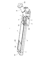
- FIG. 1 is a perspective view showing the screw conveyor of the present embodiment.
- FIG. 2 is a perspective view showing a part of the screw conveyor shown in FIG. 1 excluding a part such as a side surface on the front side of the drawing so that the internal structure can be easily understood.
- This screw conveyor 1 is installed under a machine tool. In a machine tool, chips are generated by cutting or drilling a workpiece, and coolant is applied to a processing portion where the tool hits the workpiece. Therefore, chips and coolant have fallen down from the machine tool during processing. Therefore, a screw conveyor 1 is installed on the lower side of the machine tool, receives chips and coolant, and conveys only the chips to the outside of the machine.
- a storage tank 3 is fitted in a box-shaped main body 2 whose upper side is opened.
- coolant and chips that are liquid that has fallen from the machine tool side are stored.
- the screw conveyor 1 is closed at the top of the storage tank 3 by a lid member 4, but a part of the front side of the drawing (front part of the screw conveyor 1) is opened, and coolant and chips are removed.
- a charging port 305 to be charged is formed.
- wing 502 was integrally formed with respect to the rotating shaft 501 is integrated in the storage tank 3 in the rotatable state.
- the storage tank 3 is long in the front-rear direction of the screw conveyor 1 and is V-shaped so as to be deeper from the left and right sides in the width direction to the center part (see FIG. 3), and the screw 5 is the bottom of the storage tank 3.
- the storage tank 3 is partitioned by end plates 301 and 302 whose both ends in the longitudinal direction are vertical walls.
- a through hole 321 is formed in the rear end plate 302, and the screw 5 extends further rearward through the through hole 321.
- the rotating shaft 501 of the screw 5 passes through the end plate 301 on the front side, and a bearing member is provided there through a seal member, and the screw 5 is rotatably supported by the bearing member.
- the rotation shaft 501 of the screw 5 is configured to receive rotation from the drive mechanism via a rotation transmission unit provided in the main body front portion 201.
- FIG. 3 is a front view of the main body 2 as viewed from the front side, and the configuration of the rotation transmission unit incorporated therein is indicated by a broken line.
- the drive mechanism provided in the screw conveyor 1 has a drive motor 6 installed on the rear side of the main body 2 and a shaft 11 connected to the output shaft thereof as shown in FIG. It extends under the storage tank 3 to the main body front part 201.
- the sprocket 12 is fixed to the end portion of the shaft 11, and the chain 14 is suspended between the sprocket 13 fixed to the rotating shaft 501 of the screw 5.
- the cylindrical delivery pipe 7 is fixed to the end plate 302 in accordance with the position of the through hole 321, and further on the rear side of the storage tank 3 with respect to the delivery pipe 7.
- a cylindrical discharge pipe 8 is connected. Since the screw 5 passes through the through-hole 321 and enters the delivery pipe 7, chips in the storage tank 3 are fed into the delivery pipe 7 by the screw 5.
- the delivery pipe 7 is mounted in a horizontal state so that its center line substantially coincides with the axis of the rotating shaft 501 of the screw 5, but the discharge pipe 8 connected to the delivery pipe 7 is connected to the rear side. It is attached in an inclined state so as to rise to the side. Accordingly, the screw 5 in the delivery pipe 7 has a rear end up to a position before the discharge pipe 8.
- the chips sent into the delivery pipe 7 by the screw 5 are sequentially fed into the discharge pipe 8 and accumulated in the discharge pipe 8. Then, the chips in the discharge pipe 8 are pushed up from the bottom to the top by increasing the amount of accumulation, and finally pushed out from the discharge port 801 at the rear end. Since a collection box is placed under the discharge port 801, the fallen chips are collected by the collection box.
- chips generated from machine tools are not only fine metal pieces, but also have various sizes and shapes depending on the type of processing, and long elongated chips are also generated.
- Such chips may become clogged in the screw conveyor, and the rotation of the screw 5 may be stopped.
- the screw 5 extends only to the delivery pipe 7, and the movement direction of the chips is upward in the discharge pipe 8. This makes it easier for chips to become clogged.
- the screw conveyor 1 of the present embodiment is provided with a support block 21 that rotatably supports the screw 5 in the delivery pipe 7.
- a support block 21 that rotatably supports the screw 5 in the delivery pipe 7.
- One end of the screw 5 is rotatably supported by the bearing member at the main body front portion 201, but the bearing member cannot be provided on the rear end side through which chips pass. Therefore, the outer peripheral portion of the spiral blade 502 is slidably supported by the support block 21.
- three support blocks 21 are fixed to the inner peripheral surface of the delivery pipe 7.
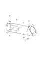
- FIG. 4 is an external perspective view showing the delivery pipe 7, and the internal support block 21 is indicated by a broken line.
- FIG. 5 is a cross-sectional view showing a part of the delivery pipe 7.
- the delivery pipe 7 includes a straight part 701 into which the screw 5 enters and a bending part 702 for connecting to the discharge pipe 8.
- the fixing flange 22 is integrally formed at the front end portion on the straight portion 701 side, and the connecting flange 23 is integrally formed on the rear end portion on the refractive portion 702 side by welding.
- the fixing flange 22 is fastened to the end plate 302 by a bolt via a seal member, and the connecting flange 23 is fastened to the flange of the discharge pipe 8 by a bolt via the seal member.
- a support block 21 is fixed on the front side. That is, in order to avoid clogging of chips, in this embodiment, all the support blocks 21 are provided at positions farther from the discharge pipe 8.
- the support block 21 rotates and supports the screw 5 on the rear side together with the bearing member of the front portion 201 of the main body so that the chips can be smoothly fed by stabilizing the rotation.
- the support block 21 since the support block 21 is present as a projection in the narrow delivery pipe 7, it becomes an obstacle to the chips sent by the screw 5, and in particular, the band-like chips are easily caught and clogging occurs. This is considered to be a factor that causes
- the support block 21 is formed in such a shape that chips are not caught as much as possible.
- the support block 21 has an arc shape with a cross section viewed in the front-rear direction widened outside, the front side portion is formed in a triangular shape, and the radial direction of the delivery pipe 7, that is, the dimension in the thickness direction is Inclined so that it becomes thicker toward the rear.
- the support block 21 may cause chips to be caught.
- the support block 21 that is considered to be the cause of the clogging was examined.
- the arrangement of the support block 21 was compared, and as a result, it was found that it is preferable to arrange the support block 21 on the front side of the delivery pipe 7 at a position far from the discharge pipe 8 as shown in FIG.
- the support block 21 is arranged on the rear side of the delivery pipe 7 close to the discharge pipe 8 (refractive portion 702), clogging occurs due to delivery of a certain amount of chips, and the rotation of the screw 5 is stopped. Will happen.
- the support block 21 is disposed on the front side as in the present embodiment, such a situation does not occur.
- the support block 21 has a small radial space between the screw 5 and the delivery pipe 7. In the discharge pipe 8, the chips are only pushed up from below by the pushing force of the screw 5, and the movement thereof is extremely reduced. Therefore, when the rear space of the delivery pipe 7 is narrowed by the support block 21, the sent chips are compressed in the rear space. In such a situation, if band-like chips or the like are caught on the support block 21, the chips are difficult to move. Therefore, it is considered that the chips are more compressed especially in the rear side space in the delivery pipe 7, and this causes clogging.
- the support block 21 is disposed on the front side of the delivery pipe 7 in consideration of making the space on the rear side of the delivery pipe 7 wider and preventing the chips from being caught. I tried to make it.
- the three support blocks 21 are aligned in the center line direction (front-rear direction) of the delivery pipe 7 (linear portion 701), and are arranged at equal intervals in the circumferential direction. Further, the diameter of the delivery tube 7 is formed in the end plate 302 larger than the diameter of the through hole 321. Therefore, the support block 21 is arranged so as to be hidden behind the end plate 302 when the delivery pipe 7 side is viewed from the storage tank 3 side.
- coolant and chips dropped from the processing chamber of the machine tool enter the storage tank 3 through the input port 305 and are sent to the rear side by the rotating screw 5.
- the coolant flows out so as to overflow from the storage tank 3 while leaving chips, returned to the tank in the main body 2, and regenerated through a filter or the like.
- the chips are sent by the screw 5 through the through hole 321 to the feed pipe 7.
- chips since chips enter according to the size of the through-hole 321, even if it is a strip-shaped chip, it is difficult to be caught on the support block 21.
- the chips sent to the rear side in the delivery pipe 7 are less likely to move gradually toward the rear side, and the density becomes higher.
- the support block 21 since the support block 21 does not exist in the back side, the clearance gap between the screw 5 and the delivery pipe
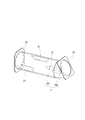
- FIG. 6 is an external perspective view showing the delivery pipe 7, and the internal support block 21 is indicated by a broken line.
- the arrangement of the support blocks 21 is different from that of the first embodiment.
- the three support blocks 21 are equally spaced in the circumferential direction, but are shifted in the center line direction (front-rear direction) of the delivery pipe 7 (straight line portion 701), and on a so-called spiral.
- the spiral directions of the three support blocks 21 include an arrangement in which the one far from the fixing flange 22 is in accordance with the rotation direction of the screw 5 and an arrangement in the direction opposite to the rotation direction.
- the three support blocks 21 are separated in the front-rear direction, but the function of rotating and supporting the screw 5 is not impaired. And although the support block 21 is arrange
- FIG. 7 is a simplified diagram showing the delivery pipe in the front-rear direction.
- the delivery pipe 27 of the third embodiment is a cylindrical pipe having a diameter larger than that of the delivery pipe 7 of the first embodiment, and similarly, three support blocks 28 and 29 are fixed to the inner peripheral surface. ing. However, one of the three support blocks 28 is formed to have a larger dimension in the radial direction of the delivery tube 27, that is, in the thickness direction, than the other two support blocks 29.
- the support block 28 is arranged at the highest position in the delivery pipe 27. In the drawing, the position of the screw 5 is indicated by a one-dot chain line, but as can be seen from this, the center of the delivery pipe 27 and the axis of the rotary shaft 501 are displaced in the vertical direction. Note that the positions of the support blocks 28 and 29 in the front-rear direction are the same as those in the first or second embodiment.
- the gap between the screw 5 and the delivery pipe 27 is widened on the upper side of the screw 5. This is because the chips sent while being stirred by the rotation of the screw 5 easily move upward. Therefore, by adopting such a configuration, it is possible to suppress chip compression and make it difficult to clog chips in the delivery pipe 27 and the discharge pipe 8.
- FIG. 8 is a simplified diagram showing the delivery pipe in the front-rear direction.
- the delivery tube 31 of the fourth embodiment is formed integrally by joining a lid 312 on a U-shaped groove-shaped main body 311.
- three support blocks 32 and 33 are fixed to the inner peripheral surface.
- one of the three support blocks 32 is formed larger than the other two support blocks 33 and is fixed to the lid 312.
- tube 31 is wide above the screw 5.
- the thick support blocks 28 and 32 are provided, and the gap between the delivery pipes 27 and 31 and the screw 5 is increased.
- the upper gap of the screw 5 is large.
- the effect of widening the gap can be obtained even if the gaps in each direction are uniform as in the first and second embodiments.
- a thin thin structure such as the screw conveyor 1
- the screw conveyance cross-sectional area corresponding to the cross-sectional area of the spiral blade 502 of the screw 5 and the delivery It is designed so that the gap cross-sectional area corresponding to the cross-sectional area excluding the support blocks 28 and 29 is substantially the same as that of the outer diameter of the spiral blade 502 between the inner diameter of the stub tube 27. .
- the screw conveyance cross-sectional area occupied by the screw 5 and the gap cutting except for the screw 5 and the support blocks 21, 32 and 33 are cut. It is preferable that the area be approximately the same.
Landscapes
- Engineering & Computer Science (AREA)
- Mechanical Engineering (AREA)
- Auxiliary Devices For Machine Tools (AREA)
- Screw Conveyors (AREA)
Abstract
貯留槽を備えた容器型の本体と、前記貯留槽に対し前端部が接続された横置きの送出し管と、前記送出し管の後端部に接続され当該接続端から他端側にかけて上方に傾斜して配置された排出管と、前記貯水槽および前記送出し管の内部に渡って配置されたスクリューと、前記送出し管とは反対側の前記貯留槽の前部に位置する軸受部材を介して前記スクリューに回転を与える駆動機構と、前記送出し管の内面の円周方向の異なる位置に前記スクリューと摺接する複数の支持ブロックが固定され、一又は二以上の前記支持ブロックが前記送出し管の前方側に固定されたスクリュー支持構造とを有するスクリューコンベア。
Description
本発明は、切屑を外部へと排出するためのスクリューコンベアに関する。
旋盤やマシニングセンタ等の工作機械では、加工に伴って切屑が発生する。そのため、その切屑を加工部から工作機械の外部へと排出するための排出コンベアが設けられている。排出コンベアは、例えば、加工部の下に切屑やクーラントを受けるための投入口を設けた貯留槽が配置され、その貯留槽内部において切屑が後方へと送られるようになっている。そして、更に上方へと傾斜して延びる排出部へと切屑が送られ、そこから排出された切屑が回収ボックスへと集められるようになっている。そうした排出コンベアには、ヒンジベルトによるチップコンベアやドラム式コンベア、或いはスクリューコンベアなど各種タイプのコンベアが存在する。そうした中、下記特許文献1にはスクリューコンベアが開示されている。
同文献における従来のスクリューコンベアは、回転軸の外周に螺旋羽根が形成されたスクリューを有し、そのスクリューは、軸受けを介して回転可能な状態で軸支され、ケーシング内に挿入されている。スクリューがケーシング内で回転することにより、工作機械から排出された切屑が螺旋羽根に押されるようにして後方へと送られる。そして、その後方側には排出管が接続されているが、この従来例では、排出管が下流側ほど拡径するように形成され、切屑が送り出される出口部分において搬送抵抗が小さくなるように構成されている。
前記従来例のスクリューコンベアは、前述したように切屑が搬送路内で詰まりを生じないように、搬送抵抗を低減させるための構成がとられている。具体的には排出管の径を広げる構成であるが、切屑はスクリューコンベアのケーシングすなわち送出し管の中でも詰まりを生じさせる。この点、前記従来例では、切屑の発生量が大きく変動した場合にも対応できるように、送出し管の下流側部分に搬送経路の容積を大きくするための収容箱が形成されている。しかし、こうした収容箱などは、上方に十分な設置スペースが取れるような構成でなければ設けることができない。更に、別構成のスクリューコンベアによっては、送出し管の下流側部分にスクリューを支持する支持構造を有するものがあり、収容箱を設けることができない場合もある。
そこで、本発明は、かかる課題を解決すべく、切屑を詰まらせにくくするスクリューコンベアを提供することを目的とする。
本発明の一態様におけるスクリューコンベアは、貯留槽を備えた容器型の本体と、前記貯留槽に対し前端部が接続された横置きの送出し管と、前記送出し管の後端部に接続され当該接続端から他端側にかけて上方に傾斜して配置された排出管と、前記貯水槽および前記送出し管の内部に渡って配置されたスクリューと、前記送出し管とは反対側の前記貯留槽の前部に位置する軸受部材を介して前記スクリューに回転を与える駆動機構と、前記送出し管の内面の円周方向の異なる位置に前記スクリューと摺接する複数の支持ブロックが固定され、一又は二以上の前記支持ブロックが前記送出し管の前方側に固定されたスクリュー支持構造とを有する。
前記構成によれば、送出し管の内周面にスクリューと摺接するように複数の支持ブロックが固定されているが、そのうちの一又は二以上のものが送出し管の前方側に位置するようにしたので、送出し管の中で送られる切屑は、後方向側へと向かうにつれて徐々に溜まって密度が高くなっていくものの、その後方側において支持ブロックが存在しないか、或いは数が少ないことにより、スクリューと送出し管との隙間が確保でき、切屑を詰まらせにくくすることができる。
次に、本発明に係るスクリューコンベアの一実施形態について、図面を参照しながら以下に説明する。ここで、図1は、本実施形態のスクリューコンベアを示した斜視図である。図2は、内部構造が分かり易くなるように、図1示すスクリューコンベアの図面手前側に位置する側面などの一部を除いて示した斜視図である。このスクリューコンベア1は、工作機械の下に設置されるものである。工作機械では、ワークの切削加工や穴あけ加工などによって切屑が発生し、また、ワークに対して工具が当たる加工部にはクーラントがかけられる。そのため、加工時の工作機械からは切屑やクーラントが下に落ちている。そこで、工作機械の下側にはスクリューコンベア1が設置され、切屑やクーラントを受け、切屑のみを機外へと搬送するようにしている。
本実施形態のスクリューコンベア1は、上側が開放された箱型の本体2の中に貯留槽3が嵌め込まれている。その貯留槽3には、工作機械側から落ちた液体であるクーラントや切屑が溜められるようになっている。スクリューコンベア1は、図2に示すように、貯留槽3の上方が蓋部材4によって閉じられているが、図面手前側の一部(スクリューコンベア1の前部)が開口し、クーラントや切屑が投入される投入口305が形成されている。そして、貯留槽3の中には、回転軸501に対して帯状の螺旋羽根502が一体に形成されたスクリュー5が、回転可能な状態で組み込まれている。
貯留槽3は、スクリューコンベア1の前後方向に長く、幅方向の左右両側から中央部分にかけて深くなるようにV字形をしたものであり(図3参照)、スクリュー5は、その貯留槽3の底部に長手方向に沿って配置されている。また、貯留槽3は、長手方向の両端部が垂直な壁となる端部板301,302によって仕切られている。図2に示すように、後方側の端部板302には貫通孔321が形成されており、スクリュー5がその貫通孔321を通って更に後方側へと延びている。一方、前方側の端部板301でもスクリュー5の回転軸501が貫通しているが、そこにはシール部材を介して軸受部材が設けられ、その軸受部材によってスクリュー5が回転支持されている。
スクリュー5の回転軸501は、本体前部201に設けられた回転伝達部を介して駆動機構からの回転を受けるように構成されている。ここで、図3は、本体2を前側から見た正面図であり、内部に組み込まれた回転伝達部の構成が破線示されている。先ず、スクリューコンベア1に設けられた駆動機構は、図1に示すように、本体2の後方側に駆動モータ6が設置され、その出力軸に連結されたシャフト11が、図3に示すように貯留槽3の下を通って本体前部201まで延びている。その本体前部201では、シャフト11の端部にスプロケット12が固定され、スクリュー5の回転軸501に固定されたスプロケット13との間にチェーン14が掛け渡されている。
次に、貯留槽3の後方側では、貫通孔321の位置に合わせて円筒形状の送出し管7が端部板302に対して固定され、更にその後方側では、送出し管7に対して円筒形状の排出管8が接続されている。スクリュー5は、貫通孔321を通って送出し管7の中にまで入り込んでいるため、貯留槽3内の切屑がスクリュー5によって送出し管7へと送り込まれるようになっている。送出し管7は、その中心線がスクリュー5の回転軸501の軸心とほぼ一致するように水平な状態で取り付けられているが、その送出し管7に接続された排出管8は、後方側に上昇するよう傾斜した状態で取り付けられている。従って、送出し管7内のスクリュー5は、その後端が排出管8の手前の位置までとなっている。
スクリューコンベア1では、スクリュー5によって送出し管7内へと送られた切屑が、次に排出管8内に順次送り込まれ、その排出管8内に堆積していく。そして、排出管8内の切屑は、その堆積量が増えることで傾斜部分を下から上へと押し上げられ、ついには後端の排出口801から押し出される。排出口801の下には回収ボックスが置かれているため、落下した切屑はその回収ボックスによって回収される。
ところで、工作機械から発生する切屑は、細かい金属片だけではなく、加工の種類によって様々な大きさや形などがあり、長く伸びた帯状の切屑なども発生する。そうした切屑はスクリューコンベア内で詰まってしまうことがあり、スクリュー5の回転を止めてしまうことがある。特に、スクリューコンベア1のような構造のものは、スクリュー5が送出し管7までしかなく、排出管8内では切屑の移動方向も上向きになるため、送出し管7と排出管8と境目部分で切屑の詰まりが生じやすくなる。
しかも、本実施形態のスクリューコンベア1は、送出し管7の中にスクリュー5を回転支持する支持ブロック21が設けられている。スクリュー5は、その一端部が本体前部201において回転軸501が軸受部材によって回転支持されているが、切屑を通過させる後端部側には軸受部材を設けることができない。そのため、支持ブロック21によって螺旋羽根502の外周部が摺接支持されている。スクリューコンベア1の場合、送出し管7の内周面に3つの支持ブロック21が固定されている。
図4は、送出し管7を示した外観斜視図であり、内部の支持ブロック21を破線で示したものである。また、図5は、送出し管7の部分を示した断面図である。この送出し管7は、スクリュー5が入る直線部701と、排出管8へと繋げるための屈折部702とから構成されている。その直線部701側の前端部には固定用フランジ22が、屈折部702側の後端部には連結用フランジ23がそれぞれ溶接によって一体に形成されている。そして、送出し管7は、固定用フランジ22が端部板302に対してシール部材を介してボルトによって締結され、連結用フランジ23が排出管8のフランジにシール部材を介してボルトによって締結される。
こうした送出し管7の中には、前方側に支持ブロック21が固定されている。すなわち、切屑の詰まりを回避するため、本実施形態では排出管8からより離れた位置に全ての支持ブロック21が設けられている。その支持ブロック21は、スクリュー5を本体前部201の軸受部材とともに後方側でも回転支持し、その回転を安定させることで切屑を円滑に送ることができるようにしたものである。ところが、狭い送出し管7の中に支持ブロック21が突起物として存在することになるため、それがスクリュー5によって送られる切屑の障害物になり、特に帯状の切屑などが引っ掛かり易く、詰まりを生じさせる要因になると考えられる。
切屑が送出し管7の中などで詰まってしまうと、スクリュー5の回転を停止させてしまう。その場合は、作業者が切屑を掻き出し、スクリュー5の回転を正常に戻さなければならなくなる。この点で、支持ブロック21は、なるべく切屑が引っ掛からないような形状で形成されている。具体的には、支持ブロック21は、前後方向に見た断面が外側を広くした円弧形状であって、前側部分は三角形状で形成され、送出し管7の径方向つまり厚さ方向の寸法が後方にかけて厚くなるように傾斜が付けられている。しかし、こうした支持ブロック21であっても切屑の引っ掛かりを生じさせてしまうことがある。
そこで、詰まりの原因と考えられる支持ブロック21に関して検討が加えられた。ここでは、特に支持ブロック21の配置について比較が行われ、その結果、図4に示すように、排出管8から遠い位置の送出し管7の前方側に配置させるのが好ましいことがわかった。例えば、逆に支持ブロック21を排出管8(屈折部702)に近い送出し管7の後方側配置にした場合は、ある一定量の切屑の送出しによって詰まりが生じ、スクリュー5の回転停止が起こってしまう。これに対して、本実施形態のように支持ブロック21を前方側配置にした場合には、そのようなことが起きなかった。
支持ブロック21の後方側配置での状況を確認したところ、屈折部702から排出管8の内側上面に切屑が強く押し付けられたようなキズが多くみられた。その原因を考えてみる。支持ブロック21は、スクリュー5と送出し管7との間の径方向のスペースを小さくしてしまっている。排出管8の中では、切屑はスクリュー5の押し込み力により下から押し上げられているだけであり、その移動が極端に低下している。従って、送出し管7の後方側空間が支持ブロック21によって狭くなってしまうと、送られてきた切屑が当該後方側空間で圧縮される。そのような状況で帯状の切屑などが支持ブロック21に引っ掛れば、切屑が移動しにくくなってしまう。よって、送出し管7内の特に後方側空間で切屑がより圧縮され、それが原因として詰まりを生じさせていると考えられる。
そこで、本実施形態では、送出し管7の後方側のスペースをより広くすることや、切屑の引っ掛かりが生じないようにすることを考慮し、支持ブロック21を送出し管7の前方側に配置させるようにした。3つの支持ブロック21は、送出し管7(直線部701)の中心線方向(前後方向)の位置が揃えられ、円周方向には等間隔に配置されている。更に、送出し管7の径は端部板302には貫通孔321の径よりも大きく形成されている。そのため、貯留槽3側から送出し管7側を見た場合には、支持ブロック21が端部板302の後方側に隠れるような配置になっている。
以上のような構成のスクリューコンベア1では、工作機械の加工室から落下したクーラントや切屑が投入口305から貯留槽3内に入り、回転するスクリュー5によって後方側へと送られる。クーラントは切屑を残して貯留槽3から溢れるようにして流れ出し、本体2内のタンクに戻され、フィルタを通すなどして再生される。一方、切屑は、スクリュー5によって貫通孔321を通って送出し管7へと送られる。その際、本実施形態では、貫通孔321の大きさに応じて切屑が入ってくるため、帯状の切屑であっても支持ブロック21には引っ掛かり難くなっている。
そして、送出し管7の中を後方側に送られる切屑は、後方向側へと向かうにつれて徐々に移動しにくくなり密度が高くなっていく。本実施形態では、その後方側に支持ブロック21が存在しないため、スクリュー5と送出し管7との隙間が確保でき、切屑が無理に押し込まれて強く圧縮されることはない。それゆえ、送出し管7や排出管8内で切屑が詰まりにくくなっている。よって、切屑の詰まりが生じないことで、スクリュー5の回転を停止させることなくスクリューコンベア1の連続運転を可能にする。
続いて、スクリューコンベアの他の実施形態について以下に説明する。なお、前記第1実施形態と同じ構成については同じ符号を付して説明する。先ず、図6は、送出し管7を示した外観斜視図であり、内部の支持ブロック21を破線で示したものである。この第2実施形態では、支持ブロック21の配置が第1実施形態のものと異なっている。具体的には、3つの支持ブロック21が円周方向には等間隔であるが、送出し管7(直線部701)の中心線方向(前後方向)にはずれた位置にあり、いわゆる螺旋上に配置されている。このとき、3つの支持ブロック21の螺旋方向は、固定用フランジ22に近いものから遠いものの配置が、スクリュー5の回転方向に倣った配置と、回転方向とは逆方向の配置とがある。
この第2実施形態では、3つの支持ブロック21が前後方向に離れているが、スクリュー5を回転支持する機能を損なうことはない。そして、切屑の密度が高くなる送出し管7の後方側にも支持ブロック21が配置されているが、1つだけであるため、詰まってしまうほどに切屑を圧縮させるようなこともない。また、支持ブロック21同士が離れて配置されているため、スクリュー5と送出し管7との隙間が全体的に確保でき、切屑の円滑な搬送を可能にしている。さらに、3つの支持ブロック21の螺旋配置をスクリュー5の回転と逆方向にすることにより、切屑がより引っ掛かり難くなると考えられる。
次に、図7は、送出し管を前後方向に示した簡略図である。第3実施形態の送出し管27は、第1実施形態の送出し管7よりも径が大きく形成された円筒管であり、同じように3つの支持ブロック28,29が内周面に固定されている。ただし、3つのうち1つの支持ブロック28が他の2つの支持ブロック29よりも送出し管27の径方向、つまり厚さ方向の寸法が大きく形成されている。そして、その支持ブロック28は送出し管27内の最も高い位置に配置されている。図面には、一点鎖線でスクリュー5の位置が示されているが、ここから分かるように送出し管27の中心と回転軸501の軸心とが上下方向にずれている。なお、支持ブロック28,29の前後方向の位置は、前記第1または第2実施形態と同じである。
本実施形態では、支持ブロック28を上部に設けることによりスクリュー5と送出し管27との隙間が、スクリュー5の上側で広くなっている。これは、スクリュー5の回転によって撹拌されながら送られる切屑は上側に移動しやすいからである。よって、このような構成にすることで、切屑の圧縮が抑えられ、送出し管27や排出管8内で切屑を詰まらせにくくすることができる。
更に、図8は、送出し管を前後方向に示した簡略図である。この第4実施形態の送出し管31は、U字形の溝形本体311の上に蓋体312が接合されて一体に形成されたものである。そして、同じく3つの支持ブロック32,33が内周面に固定されている。ただし、3つのうち1つの支持ブロック32が他の2つの支持ブロック33よりも大きく形成され、蓋体312に固定されている。そして、本実施形態でもスクリュー5と送出し管31との隙間が、スクリュー5の上側で広くなっている。よって、スクリュー5が回転して撹拌されながら送られる切屑は上側に移動しやすくなり、切屑の圧縮が抑えられ、送出し管31や排出管8内で切屑を詰まらせにくくすることができる。
ところで、第3及び第4実施形態では、厚みのある支持ブロック28,32を設けて送出し管27,31内におけるスクリュー5との隙間が大きくなっている。特にスクリュー5の上側の隙間が大きくなっている。しかし、隙間拡大の効果は、第1及び第2実施形態のように各方向の隙間が均等であっても良い結果が得られる。一方で、スクリューコンベア1のように背の低い薄型構造の場合には送出し管の径をあまり大きくすることは好ましくない。そこで、隙間の観点から切屑の詰まり防止とコンパクト化の要求に対応する構成を検討したところ、次のような構成が好ましいことが分かった。
具体的に図7の例では、送出し管27の内部を中心線方向(図面を貫く方向)に見た場合に、スクリュー5の螺旋羽根502の断面積に相当するスクリュー運搬断面積と、送出し管27の内径との間の螺旋羽根502の外径との隙間部分であって、支持ブロック28,29を除く断面積に相当する隙間断面積とが、ほぼ同程度になるように設計する。送出し管7,31の場合も同様であり、その内部を中心線方向に見た場合に、スクリュー5が占めるスクリュー運搬断面積と、そのスクリュー5と支持ブロック21,32,33を除く隙間断面積とがほぼ同じになるようにすることが好ましい。
以上、本発明の一実施形態について説明したが、本発明はこれらに限定されるものではなく、その趣旨を逸脱しない範囲で様々な変更が可能である。
例えば、支持ブロックの形状や配置位置などについて更に別の構成であってもよい。
例えば、支持ブロックの形状や配置位置などについて更に別の構成であってもよい。
1…スクリューコンベア 2…本体 3…貯留槽 5…スクリュー 7…送出し管 8…排出管 21…支持ブロック
Claims (5)
- 貯留槽を備えた容器型の本体と、
前記貯留槽に対し前端部が接続された横置きの送出し管と、
前記送出し管の後端部に接続され当該接続端から他端側にかけて上方に傾斜して配置された排出管と、
前記貯水槽および前記送出し管の内部に渡って配置されたスクリューと、
前記送出し管とは反対側の前記貯留槽の前部に位置する回転伝達部を介して前記スクリューに回転を与える駆動機構と、
前記送出し管の内面の円周方向の異なる位置に前記スクリューと摺接する複数の支持ブロックが固定され、一又は二以上の前記支持ブロックが前記送出し管の前方側に固定されたスクリュー支持構造と
を有するスクリューコンベア。 - 前記スクリュー支持構造は、全ての前記支持ブロックが前記送出し管の前方側に設けられた請求項1に記載のスクリューコンベア。
- 前記スクリュー支持構造は、全ての前記支持ブロックが前記送出し管の長手方向の異なる位置に設けられた請求項1に記載のスクリューコンベア。
- 前記スクリュー支持構造は、前記スクリューの軸心上部に位置する前記支持ブロックが他の位置の前記支持ブロックより径方向に大きく形成され、前記スクリューの軸心と前記送出し管の中心線とがずれている請求項1乃至請求項3のいずれかに記載のスクリューコンベア。
- 前記送出し管の内部を中心線方向に見て、前記スクリューの螺旋羽根の断面積に相当するスクリュー運搬断面積と、前記送出し管の内径との間の前記螺旋羽根の外径との隙間部分であって前記支持ブロックを除く断面に相当する隙間断面積とが同程度である請求項1乃至請求項4のいずれかに記載のスクリューコンベア。
Priority Applications (4)
| Application Number | Priority Date | Filing Date | Title |
|---|---|---|---|
| CN201780090297.7A CN110582374B (zh) | 2017-05-08 | 2017-05-08 | 螺旋输送机 |
| PCT/JP2017/017408 WO2018207241A1 (ja) | 2017-05-08 | 2017-05-08 | スクリューコンベア |
| JP2019516757A JP6857238B2 (ja) | 2017-05-08 | 2017-05-08 | スクリューコンベア |
| US16/609,382 US10793368B2 (en) | 2017-05-08 | 2017-05-08 | Screw conveyer |
Applications Claiming Priority (1)
| Application Number | Priority Date | Filing Date | Title |
|---|---|---|---|
| PCT/JP2017/017408 WO2018207241A1 (ja) | 2017-05-08 | 2017-05-08 | スクリューコンベア |
Publications (1)
| Publication Number | Publication Date |
|---|---|
| WO2018207241A1 true WO2018207241A1 (ja) | 2018-11-15 |
Family
ID=64105538
Family Applications (1)
| Application Number | Title | Priority Date | Filing Date |
|---|---|---|---|
| PCT/JP2017/017408 Ceased WO2018207241A1 (ja) | 2017-05-08 | 2017-05-08 | スクリューコンベア |
Country Status (4)
| Country | Link |
|---|---|
| US (1) | US10793368B2 (ja) |
| JP (1) | JP6857238B2 (ja) |
| CN (1) | CN110582374B (ja) |
| WO (1) | WO2018207241A1 (ja) |
Cited By (1)
| Publication number | Priority date | Publication date | Assignee | Title |
|---|---|---|---|---|
| CN114258382A (zh) * | 2019-08-28 | 2022-03-29 | 东京精密发条株式会社 | 螺旋输送机 |
Families Citing this family (1)
| Publication number | Priority date | Publication date | Assignee | Title |
|---|---|---|---|---|
| SE547884C2 (en) * | 2024-06-13 | 2025-12-16 | Valmet Oy | Material transport arrangement comprising a housing being larger than a helical screw blade |
Citations (7)
| Publication number | Priority date | Publication date | Assignee | Title |
|---|---|---|---|---|
| JPS59165828U (ja) * | 1983-04-20 | 1984-11-07 | 金田 益治 | スクリユ−コンベヤ |
| JPH0364910U (ja) * | 1989-10-31 | 1991-06-25 | ||
| JPH043711A (ja) * | 1990-04-18 | 1992-01-08 | Tokyo Seimitsu Hatsujo Kk | 螺旋型コンベアにおける搬送路の構造及び該構造に用いる突条部材 |
| JP2000126978A (ja) * | 1998-10-20 | 2000-05-09 | Sogo Hatsujo Kk | 切削屑処理装置 |
| JP2002154030A (ja) * | 2000-11-15 | 2002-05-28 | Tokyo Seimitsu Hatsujo Kk | 切削物の搬送装置 |
| JP2010284753A (ja) * | 2009-06-12 | 2010-12-24 | Tekutowan:Kk | 切削廃棄物の濾過搬送処理装置 |
| US20150017048A1 (en) * | 2013-07-02 | 2015-01-15 | Kenneth Blanchard | Single flight screw, a single flight high pressure screw pump and compactor containing such a pump |
Family Cites Families (10)
| Publication number | Priority date | Publication date | Assignee | Title |
|---|---|---|---|---|
| US2818165A (en) * | 1954-12-07 | 1957-12-31 | Dupps Co | Screw conveyor |
| JPS59165828A (ja) * | 1983-03-09 | 1984-09-19 | Mitsubishi Heavy Ind Ltd | ガスタ−ビンのガス膨張冷却器 |
| IT1224364B (it) * | 1988-05-11 | 1990-10-04 | Trasportatori Govoni Srl | Metodo, macchina e impianto per l'evacuazione, il convogliamento, la compattazione e lo scarico di materiali sfusi, in particolare trucioli e sfridi |
| JPH08108918A (ja) * | 1994-10-12 | 1996-04-30 | Suzuki Motor Corp | 切削屑搬送装置 |
| DE102007044289A1 (de) * | 2007-09-07 | 2009-03-12 | Ex-Cell-O Gmbh | Werkzeugmaschinenvorrichtung, Werkzeugmaschine und Verfahren zur Herstellung einer Werkzeugmaschinenvorrichtung |
| JP2012056065A (ja) | 2010-09-13 | 2012-03-22 | Mazda Motor Corp | 切粉搬送装置 |
| KR101460409B1 (ko) * | 2012-11-12 | 2014-11-12 | 임영호 | 칩 스크루 컨베이어 장치 |
| KR101498634B1 (ko) * | 2013-05-09 | 2015-03-04 | 송규태 | 자동 선반의 칩 이송장치 |
| CN108136557B (zh) * | 2015-09-30 | 2020-10-09 | 株式会社富士 | 螺旋输送机 |
| TWI707815B (zh) * | 2016-06-22 | 2020-10-21 | 日商東京精密發條有限公司 | 靜音螺旋輸送機 |
-
2017
- 2017-05-08 US US16/609,382 patent/US10793368B2/en active Active
- 2017-05-08 WO PCT/JP2017/017408 patent/WO2018207241A1/ja not_active Ceased
- 2017-05-08 CN CN201780090297.7A patent/CN110582374B/zh active Active
- 2017-05-08 JP JP2019516757A patent/JP6857238B2/ja active Active
Patent Citations (7)
| Publication number | Priority date | Publication date | Assignee | Title |
|---|---|---|---|---|
| JPS59165828U (ja) * | 1983-04-20 | 1984-11-07 | 金田 益治 | スクリユ−コンベヤ |
| JPH0364910U (ja) * | 1989-10-31 | 1991-06-25 | ||
| JPH043711A (ja) * | 1990-04-18 | 1992-01-08 | Tokyo Seimitsu Hatsujo Kk | 螺旋型コンベアにおける搬送路の構造及び該構造に用いる突条部材 |
| JP2000126978A (ja) * | 1998-10-20 | 2000-05-09 | Sogo Hatsujo Kk | 切削屑処理装置 |
| JP2002154030A (ja) * | 2000-11-15 | 2002-05-28 | Tokyo Seimitsu Hatsujo Kk | 切削物の搬送装置 |
| JP2010284753A (ja) * | 2009-06-12 | 2010-12-24 | Tekutowan:Kk | 切削廃棄物の濾過搬送処理装置 |
| US20150017048A1 (en) * | 2013-07-02 | 2015-01-15 | Kenneth Blanchard | Single flight screw, a single flight high pressure screw pump and compactor containing such a pump |
Cited By (1)
| Publication number | Priority date | Publication date | Assignee | Title |
|---|---|---|---|---|
| CN114258382A (zh) * | 2019-08-28 | 2022-03-29 | 东京精密发条株式会社 | 螺旋输送机 |
Also Published As
| Publication number | Publication date |
|---|---|
| US10793368B2 (en) | 2020-10-06 |
| JPWO2018207241A1 (ja) | 2019-12-26 |
| US20200055676A1 (en) | 2020-02-20 |
| CN110582374A (zh) | 2019-12-17 |
| JP6857238B2 (ja) | 2021-04-14 |
| CN110582374B (zh) | 2021-07-20 |
Similar Documents
| Publication | Publication Date | Title |
|---|---|---|
| JP5558275B2 (ja) | 工作機械の切屑排出装置 | |
| KR101556967B1 (ko) | 칩 배출용 컨베이어장치 | |
| JPH09300171A (ja) | 濾過装置及び濾過システム | |
| US9272380B2 (en) | Chip conveyer for machine tool | |
| JP6586296B2 (ja) | 工作機械の切屑排出装置 | |
| CN108430694A (zh) | 过滤装置 | |
| CN108136557A (zh) | 螺旋输送机 | |
| JP5435675B2 (ja) | チップ搬送コンベヤ | |
| CN110582374B (zh) | 螺旋输送机 | |
| JP2010036317A (ja) | チップコンベア | |
| JP2010240831A (ja) | チップコンベヤ装置 | |
| JP4767661B2 (ja) | 路面切削装置およびこれを備えた路面切削車両並びにフィルタ目詰まり防止方法 | |
| KR102949761B1 (ko) | 스파이럴 컨베이어 | |
| KR101476676B1 (ko) | 자유 구동 방식의 아이들 드럼을 구비하는 오일 스키머 | |
| JP4473596B2 (ja) | 破砕処理装置付きコンベア装置、および、コンベア装置取り付け用破砕処理装置 | |
| CN105081865B (zh) | 具备切屑输送机的机床 | |
| JP6419142B2 (ja) | クーラント濾過装置 | |
| JP5676811B1 (ja) | コンベア装置 | |
| JP6530076B2 (ja) | スタッフィングスクリュー | |
| JP5198589B2 (ja) | 濾過装置 | |
| JP6736639B2 (ja) | クーラント処理装置 | |
| JP3255372U (ja) | マグネットセパレータ | |
| JP6736641B2 (ja) | クーラント処理装置 | |
| JP3166971U (ja) | 濾過装置 | |
| JP6736153B2 (ja) | バケットコンベヤ |
Legal Events
| Date | Code | Title | Description |
|---|---|---|---|
| 121 | Ep: the epo has been informed by wipo that ep was designated in this application |
Ref document number: 17909584 Country of ref document: EP Kind code of ref document: A1 |
|
| ENP | Entry into the national phase |
Ref document number: 2019516757 Country of ref document: JP Kind code of ref document: A |
|
| NENP | Non-entry into the national phase |
Ref country code: DE |
|
| 122 | Ep: pct application non-entry in european phase |
Ref document number: 17909584 Country of ref document: EP Kind code of ref document: A1 |