WO2018199331A1 - 保護キャップ - Google Patents
保護キャップ Download PDFInfo
- Publication number
- WO2018199331A1 WO2018199331A1 PCT/JP2018/017322 JP2018017322W WO2018199331A1 WO 2018199331 A1 WO2018199331 A1 WO 2018199331A1 JP 2018017322 W JP2018017322 W JP 2018017322W WO 2018199331 A1 WO2018199331 A1 WO 2018199331A1
- Authority
- WO
- WIPO (PCT)
- Prior art keywords
- connection terminal
- optical connection
- adhesive
- protective cap
- cylindrical
- Prior art date
- Legal status (The legal status is an assumption and is not a legal conclusion. Google has not performed a legal analysis and makes no representation as to the accuracy of the status listed.)
- Ceased
Links
Images




Classifications
-
- G—PHYSICS
- G02—OPTICS
- G02B—OPTICAL ELEMENTS, SYSTEMS OR APPARATUS
- G02B6/00—Light guides; Structural details of arrangements comprising light guides and other optical elements, e.g. couplings
- G02B6/24—Coupling light guides
- G02B6/36—Mechanical coupling means
Definitions
- the present invention relates to a novel protective cap for protecting the connection surface of an optical fiber optical connection terminal.
- a protective cap is used to prevent contamination of the front end surface of the optical connection terminal.
- an object of the present invention is to provide means for preventing contamination of an optical connection terminal even if dust is present on a wall surface of a protective cap.
- the present invention (1) is a protective cap capable of protecting an optical connection terminal assembled to an optical fiber terminal unit, A cap portion including a cylindrical portion in which one end portion can be fitted with the optical connection terminal and a bottom portion provided at the other end portion of the cylindrical portion; Provided inside the cap portion, and when the optical connection terminal is inserted into the cap portion through the tubular portion, the tip of the inserted optical connection terminal can be contacted An adhesive portion arranged in a position; A protective cap having The present invention (2) is a protective cap capable of protecting the optical connection terminal assembled to the optical fiber terminal unit, A cylindrical portion into which the optical connection terminal can be inserted; and The cylindrical part is provided on the surface, and when the optical connection terminal is inserted into the cylindrical part, there is a through-hole through which the optical connection terminal can pass through the cylindrical part to the inside.
- the case part is separable into a lid part on which the cylindrical part is provided on a surface and a bottom part on which the adhesive part is provided. It is a protective cap of the said invention (2).
- the present invention (4) is the protective cap according to the invention (2) or (3) for insertion of a plurality of optical connection terminals and / or optical connection terminals having different shapes.
- the present invention (5) is the protective cap according to any one of the inventions (1) to (4), wherein the cylindrical portion is made of a flexible molding resin.
- the present invention (6) is the protective cap of the invention (5), wherein the flexible molding resin is polyethylene and / or polypropylene.
- the said protective cap is, Used for an optical connection terminal having a first locking portion; Including the tubular portion having a second locking portion; When the optical connection terminal is inserted into the tubular portion, At the position where the tip of the optical connection terminal and the adhesive part abut, A second locking portion of the tubular portion; A first locking portion of the optical connection terminal;
- the protective cap according to any one of the inventions (1) to (4), wherein the caps are mutually locked.
- the present invention (8) is the protective cap according to any one of the inventions (1) to (7), wherein the adhesive portion includes a resin foam having an open cell structure.
- This invention (9) is the protective cap of the said invention (8) in which the said adhesion part contains a base material further.
- the protective cap is When the light is emitted from the optical fiber attached to the optical connection terminal with the cap part or the case part being brought into contact with the tip of the optical connection terminal and the adhesive part.
- the present invention (11) is the protective cap according to the invention (10), wherein the material of the adhesive portion is transparent and the refractive index is 1.43 to 1.55.
- This invention (12) is the protective cap of the said invention (10) or (11) whose material of the said adhesion part is an acrylic adhesive.
- an adhesive portion that contacts the end of the optical connection terminal is provided in the protective cap. Even if dust is present on the end face of the optical connection terminal, the adhesive part can remove the dust (cleaner function), and (3) the dust is present on the wall surface of the protective cap, and the dust is light. Even if it adheres to the tip of the connection terminal, the adhesive portion can remove the dust (recontamination prevention function).
- the lid has a flexible retaining material (for example, PE, PP, etc.), the bottom Can use materials that are compatible with the adhesive of the adhesive part (for example, PC, ABS, PC + ABS, etc.), (2) If the adhesive effect is lost, replace only the bottom with a new member and function The effect that can be reproduced.
- the present invention in addition to the above-described effect, there is an effect that a plurality of optical connection terminals can be simultaneously handled.
- the present invention (5) by using a specific material in the cylindrical portion and the adhesive portion, it becomes easy to press-fit and hold the optical connection terminal in the cylindrical portion, and an excellent cleaning function, termination function, etc. can be exhibited. There is an effect.
- the present invention (6) By using a specific material in the cylindrical part and the adhesive part, it is possible to easily press-fit and hold the optical connection terminal in the cylindrical part, and to exhibit an excellent cleaning function and termination function.
- this invention (7) in addition to the said effect, there exists an effect that an optical connection terminal and a protective cap can be fixed reliably, and it can prevent that an optical connection terminal remove
- an excellent cleaning function can be provided by using a resin foam for the adhesive portion, and for example, even if a pin at the tip of an optical connection terminal with a pin is pierced, a pin or the like There is an effect that there is no contamination.
- the resin foam by using a resin foam and a base material for the adhesive part, the resin foam can provide flexibility, and an excellent cleaning function can be imparted. There is an effect.
- the present invention (10) in addition to the above effects, (1) it is possible to provide an optical termination function to the optical connection terminal. (2) When the connector processing is applied to the tip of the optical fiber, There is an effect that the return loss can be measured for the purpose of confirming the processing state.
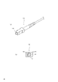
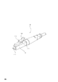
- FIG. 1 is a perspective view of an optical connection terminal assembled at the tip of an optical fiber and a side sectional view of the tip.
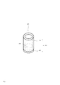
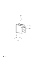
- FIG. 2 is a perspective view of an example 1 of the protective cap according to the present embodiment.
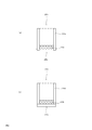
- FIG. 3 is a side sectional view showing the structure of the first aspect of the protective cap according to the present embodiment.
- FIG. 4 is an operation diagram of the first aspect of the protective cap according to the present embodiment.
- FIG. 5 is a perspective view of aspect example 2 of the protective cap according to the present embodiment.
- FIG. 6 is a perspective view illustrating another aspect of aspect example 2 of the protective cap according to the present embodiment.
- FIG. 7 is a development view of a second example of the protective cap according to the present embodiment.
- FIG. 8 is an operation diagram of the aspect example 2 of the protective cap according to the present embodiment.
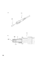
- FIG. 9 is a perspective view of the optical connection terminal assembled at the tip of the optical fiber according to the third example of the protective cap according to the present embodiment.
- FIG. 10 is a perspective view of an example 3 of the protective cap according to the present embodiment.
- FIG. 11 is a perspective view of another aspect of aspect example 3 of the protective cap according to the present embodiment.
- FIG. 12 is an operation diagram of the aspect example 3 of the protective cap according to the present embodiment.
- FIG. 13 is a side cross-sectional view showing the structure of a third aspect of the protective cap according to the present embodiment.
- the protective cap according to the present invention (for example, FIGS. 2 and 5) This is a protective cap that can protect the tip 110 of the optical connection terminal 100 (FIG. 1) assembled to the optical fiber terminal.
- Example 1 of protective cap The example 1 of the aspect which concerns on this invention is demonstrated according to FIG.
- a cap portion 210 including a cylindrical portion 211 into which the optical connection terminal 100 can be inserted, and a bottom portion 220 provided at the other end of the cylindrical portion; and provided inside the cap portion 210;
- the adhesive 111 is disposed at a position where the tip 111 of the optical connection terminal can be contacted.
- a protective cap 200 having a portion 230.
- the protective cap 200 has optical termination properties when light is emitted from an optical fiber attached to the optical connection terminal 100 with the tip 111 of the optical connection terminal 100 and the adhesive portion 230 in contact with each other. You may have the light absorption part which exhibits.
- the shape of the protective cap 200 is not particularly limited, and can be manufactured according to the shape of the optical connection terminal.
- the cap part 210 includes a cylindrical part 211 and a bottom part 220 which will be described in detail later, and further includes an adhesive part 230 which will be described later, and optionally a light absorption part which will be described in detail later. Can do.
- the cap part 210 can be separated into the cylindrical part 211 and the bottom part 220 provided with the adhesive part 230, and can be fixed during use.
- FIG. 2 shows an example in which the cylindrical portion and the bottom portion can be assembled by fitting each other.
- the cylindrical portion and the bottom portion can be fixed using a simple fitting fixing method, a fixing method using a nail, a fixing method using a screw, a fixing method using insertion, a fixing method using adhesion, or the like. it can.
- a simple fitting fixing method a fixing method using a nail, a fixing method using a screw, a fixing method using insertion, a fixing method using adhesion, or the like. it can.
- the material of the cylindrical portion 211 is made of a material excellent in insertion property with the optical fiber tip portion
- the material of the bottom portion 220 is made of a material excellent in adhesion (adhesion) with the adhesive portion 230. It becomes easy.
- the material of the cap part 210 is not particularly limited, and examples thereof include resin, metal, ceramics, and glass.
- the cylindrical portion 211 and the bottom portion 220 may be made of the same material or different materials. The thing suitable for the characteristic of each site
- the cylindrical part 211 in the present invention is a main part constituting the cap part 210.
- the size and shape of the cylindrical portion are not particularly limited, and for example, it is preferable to match the size and shape of the optical connection terminal 100 assembled to the optical fiber terminal portion or the tip portion thereof. (For example, a cylindrical shape or a rectangular tube shape).
- size and shape of the said cylindrical part when the said optical connection terminal is inserted, the magnitude
- the distal end surface 111 of the optical connection terminal abuts on the surface of the adhesive portion 230 provided in the cap, or the light
- the front end surface 111 of the connection terminal can be designed to push the surface of the adhesive part 230.
- the cylindrical portion 211 can be designed to have a structure that can be locked by using a claw portion provided in the optical connection terminal 100 when the optical connection terminal 100 is inserted.
- the material of the cylindrical portion 211 is not particularly limited, and examples thereof include metals, ceramics, resins, and glass.
- the material of the cylindrical portion 211 is preferably a resin, more preferably a flexible molded resin, considering that the optical connection terminal 100 is repeatedly inserted and the optical connection terminal 100 is not damaged, and the adhesive portion 230 is more preferable.
- More preferred are polyethylene resins and polypropylene resins having low adhesiveness. Since the polyethylene resin and the polypropylene resin have a relatively high surface energy, the adhesive force of the adhesive is not high. Therefore, when exchanging the adhesive part 230, it can be easily peeled off from the cylindrical part 211, and a part of the adhesive part 230 is difficult to adhere to the cylindrical part 211.
- the tip surface 111 of the optical connection terminal 100 into which the deposit is inserted may be contaminated. Moreover, when the optical connection terminal is inserted into the polyethylene resin or polypropylene resin, the optical connection terminal has high retention (the optical connection terminal is difficult to come off).
- the flexible molding resin in the present invention includes a thermoplastic resin, a thermosetting resin, a rubber and the like having an elastic modulus of 1 to 1000 MPa.
- Adhesive part The adhesive part 230 in the present invention is in contact with the inserted distal end surface 111 of the optical connection terminal, or after the distal end surface 111 of the optical connection terminal pushes the surface of the adhesive part 230, the optical connection By removing the terminal, contaminants such as dust adhering to the optical connection terminal tip surface 111 can be removed.
- the adhesive portion 230 has an adhesive force sufficient to remove dust and the like attached to the optical connection terminal distal end surface 111, and the optical connection terminal distal end surface 111 or the optical connection terminal that has been contacted or pressed. It can be adjusted to have an internal cohesive force that prevents the adhesive from adhering to the tip 110.
- the adhesive part 230 can be a substantially transparent adhesive, and can have a refractive index that is the same as or slightly larger than the refractive index of the optical fiber, as will be described later.
- substantially transparent means not only a completely transparent state but also a state that can transmit most of the incident light, for example, a state where the light transmittance is 80% or more.
- the optical connection terminal is attached to the optical connection terminal by bringing the front end surface 111 of the optical connection terminal into contact with the adhesive portion 230 or pressing the front end 110 of the optical connection terminal into the adhesive portion 230. Light emitted from the optical fiber is not reflected at the interface between the tip of the optical fiber and the adhesive, but can be transmitted and diffused into the adhesive part.
- the diffused light can be absorbed by the bottom part 220 of the cap part 210 which is a light absorbing part.
- the adhesive section 230 can have a so-called optical termination function in which light emitted from the optical fiber is not reflected by the optical fiber by being combined with a light absorbing section described later. Thereby, in the return loss measurement performed after wiring processing, a high return loss, that is, a non-reflection state or a substantially non-reflection state can be obtained at the end.
- the adhesive portion 230 is provided in the cap portion 210, and the thickness thereof is not particularly limited, but is 0.05 mm or more, preferably 1 mm or more, more preferably 3 mm or more. If the thickness of the adhesion part 230 is 3 mm or more, even if it is a case where the MPO connector which has a pin is contact
- the material of the adhesive part 230 is not particularly limited, and examples thereof include an adhesive, a resin foam, and a gel material. Among these, a pressure-sensitive adhesive having high internal cohesive force and tackiness, and a resin foam having an open-cell structure are preferable. More preferred is a resin foam having
- UV curable pressure-sensitive adhesive examples include those composed of an elastic polymer, an ultraviolet crosslinkable resin, a polymerization initiator, a polymerization inhibitor, and the like.
- the elastic polymer examples include acrylic resin, saturated polyester resin, polyurethane resin, and silicone resin. Of these, acrylic resins are preferred. Acrylic resin is relatively easy to arrange physical properties in order to achieve both performances such as dust removal and adhesive residue resistance.
- the acrylic resin examples include a copolymer of an acrylate monomer and another copolymerizable monomer.
- the copolymer uses the acrylate monomer capable of forming a polymer having a low glass transition point as a main monomer in order to impart tackiness, and also provides internal cohesiveness.
- a monomer capable of forming a polymer having a high glass transition point, and a monomer having a functional group such as a carboxylic acid group, an amide group, a glycidyl group, and a hydroxyl group in order to improve crosslinkability and adhesion. Can be obtained by using.
- acrylate monomer examples include acrylate alkyl esters such as ethyl acrylate, butyl acrylate, and 2-ethylhexyl acrylate.
- Examples of the monomer capable of forming a polymer having a high glass transition point include vinyl acetate, acrylonitrile, styrene, methyl acrylate, and methyl methacrylate.
- Examples of the monomer having a functional group such as carboxylic acid group, amide group, glycidyl group, and hydroxyl group include acrylic acid, methacrylic acid, itaconic acid, hydroxylethyl methacrylate, hydroxylpropyl methacrylate, acrylamide, and glycidyl methacrylate. Can be mentioned.
- Examples of the ultraviolet crosslinkable resin include oligomers that are cross-linked by irradiation with ultraviolet rays in a specific wavelength region, or acrylic acid esters or methacrylic acid esters as monomers, and these include at least 2 in the molecule. It is preferable to have one acryloyl group or methacryloyl group.
- oligomer examples include oligoester acrylate, and examples of the monomer include 1,6-hexanediol acrylate, trimethylolpropane triacrylate, tetramethylolmethane tetraacrylate, dipentaerythritol hexaacrylate, and the like.
- Ester of polyhydric alcohol and acrylic acid, or ester of polyhydric alcohol such as 1,6-hexanediol diacrylate, trimethylolpropane triacrylate, tetramethylolmethane tetraacrylate, dipentaerythritol hexaacrylate and methacrylic acid Etc.
- urethane acrylate, epoxy acrylate, and the like can be given.
- the UV-curing pressure-sensitive adhesive for example, 0.5 to 50 parts by weight, preferably 0.5 to 10 parts by weight of the ultraviolet-crosslinkable resin is blended with 100 parts by weight of the elastic polymer. That's fine. If it is less than 0.5 part by weight, the adhesive strength of the UV curable adhesive may not substantially change before and after the ultraviolet irradiation, whereas if it exceeds 50 parts by weight, the UV curable adhesive will be cured after the ultraviolet irradiation. Too much, there is a risk that the adhesive strength is reduced.
- the polymerization initiator is used for accelerating the crosslinking of the ultraviolet crosslinkable resin by ultraviolet irradiation, and a known polymerization initiator can be appropriately used.
- these polymerization initiators include benzoin alkyl ethers such as benzoin methyl ether and benzoin propyl ether, aromatic oxyketones such as benzoin, benzyl and benzophenone, aromatic ketones, benzyldimethyl ketal and polyvinylbenzophenone. be able to.
- the blending amount of the polymerization initiator is 0.1 to 20 parts by weight, preferably 0.5 to 10 parts by weight with respect to 100 parts by weight of the elastic polymer. If the amount is less than 0.1 parts by weight, the crosslinking of the UV-crosslinkable resin does not proceed even when irradiated with ultraviolet rays, so that adhesiveness is hardly expressed, and adhesive residue is likely to occur, which may cause problems. Even if it exceeds 20 parts by weight, the effect as a polymerization initiator does not change so much and is not economical.
- a resin foam having an open cell structure can be obtained by foaming an acrylic resin, a saturated polyester resin, a polyurethane resin, a silicone resin, or the like.
- a resin foam (micro sucker) disclosed in JP2012-56985A is suitable.
- the structure of the resin foam is not particularly limited as long as pores having an open-cell structure are present on the surface of the resin foam.
- the pore density on the surface of the resin foam is 10 / mm 2 to 300 / Mm 2 , preferably 30 pieces / mm 2 to 200 pieces / mm 2 , more preferably 50 pieces / mm 2 to 150 pieces / mm 2 .
- the number of holes (hole density) on the surface of the resin foam is within such a range, when the tip of the optical connection terminal comes into contact with the resin foam, the followability of the resin foam to the tip is improved and dust The takeability is improved.
- the resin foam surface has a pore density of 10 randomly selected surfaces of the resin foam surface using an optical microscope or a scanning electron microscope, and the number of holes per field area of the captured image. It can be measured and averaged.
- the method for producing the resin foam is not particularly limited, and the resin foam can be produced by a known method.
- the resin foam may be produced by either chemical foaming or physical foaming, and may be an open-cell foam in which closed cells are formed and then physically communicated by pulverizing the bubbles.
- a foam production method disclosed in JP 2012-56985 A is suitable.
- the soft polyurethane resin generally called a polyurethane gel
- a polyurethane gel can be used.
- the adhesive force of the gel material is weak, dust and the like can be removed from the front end surface of the optical connection terminal due to the embedding effect due to the softness of the soft polyurethane.
- the gel material is slightly adhesive, the optical connection terminal can be easily detached, and no adhesive residue will be generated. Clean the surface of the soft polyurethane with dust on it with a dust-free cloth moistened with water. And can be reused.
- a soft composition disclosed in JP-A-2001-316448 is suitable.
- the pressure-sensitive adhesive preferably has a gel fraction of 60% or more, more preferably 85% or more.
- the degree of cross-linking is related to the cohesive force of the pressure-sensitive adhesive at normal temperature or high temperature.
- the gel fraction is less than 60%, the fluidity increases and the optical connection terminal tip surface 111 is glued. It can cause the rest.
- the gel fraction is 60 or more, the balance between the anti-glue resistance and the tack property (dust removal performance) is excellent, and the distal end surface of the optical connection terminal or the distal end portion is attached to the adhesive portion 230 for a relatively long time. Even if it is abutted or pushed in, it is difficult to leave glue.
- Gel fraction an organic solvent such as ethyl acetate is used as a solvent, and the adhesive is immersed in the solvent at a temperature of 30 ° C. and sufficiently swollen, and then the insoluble matter is reduced to a 200 mesh net. After filtering and drying the solvent, its weight can be measured and calculated by the following formula.
- Gel fraction (%) (dry weight after filtration after solvent immersion / weight before solvent immersion) ⁇ 100
- the refractive index of the adhesive part 230 can be the same as or slightly larger than the refractive index of the optical fiber in order to prevent reflection by the surface of the adhesive part 230. Specifically, it is preferably 1.40 to 1.65, more preferably 1.43 to 1.55. The refractive index can be measured according to JIS K7142.
- the light absorbing part according to the present invention has the following effects when the adhesive part is made of a substantially transparent adhesive having the same refractive index as the optical fiber or a slightly larger refractive index. be able to.
- the light absorption part exhibits optical termination when the tip 110 of the optical connection terminal is brought into contact with or pushed into the adhesive part 230 and light is emitted from the optical fiber attached to the optical connection terminal. .
- the light emitted from the optical fiber attached to the optical connection terminal is not reflected at the interface between the optical fiber tip and the adhesive, but penetrates and diffuses into the adhesive part, and is absorbed by the light absorption part. .
- the light absorbing part includes the cap part 210 and the bottom part 220, and can absorb light diffused by the adhesive part 230 by coloring at least the inner surface or the outer surface of the cap part 210. it can.
- the bottom part 220 which is the light absorbing part, may be separable from the cylindrical part 211. In this case, when the adhesive force of the adhesive part 230 is reduced, the adhesive part 230 and the bottom part 220 are replaced with new ones. The cleaning function can be regenerated by replacing with.
- the material of the light absorbing portion is not particularly limited, but at least the bottom 220 itself, the inner surface, or the outer surface on which the adhesive portion 230 is provided can be colored.
- the light absorbing portion may be an integral structure made of a colored material, or may be colored on the inner surface of a case of a certain material or a thin film layer such as a paint or a film made of another material.
- a plate material lining or the like may be provided.
- the adhesive force between the light absorbing part and the adhesive part 230 is stronger than the adhesive force between the tubular part 211 and the adhesive part 230.
- the adhesive part 230 and the bottom part 220 are replaced with new ones.
- the adhesive part 230 can be replaced without leaving an adhesive on the side of the cylindrical part 211.
- the material having good compatibility with the adhesive part 230 include polycarbonate (PC) resin, acrylonitrile / butadiene / styrene (ABS) copolymer resin, or a mixed resin of PC resin and ABS resin.
- the light absorbing portion is preferably a structure made of a colored resin in terms of the above and the ease of manufacture and inexpensiveness, and is more preferably a structure made of a colored PC resin, ABS resin, or a mixed resin thereof. Is preferred.
- the above-mentioned colored PC resin, ABS resin, or mixed resin thereof can be produced by a known manufacturing method.
- the colorant is not particularly limited as long as it can absorb light emitted from the optical fiber. Considering the ease of light absorption, a black colorant is preferable, and examples thereof include carbon black and phthalocyanine blue.
- the amount of the colorant added is not particularly limited, but is preferably 0.1 to 10% by weight with respect to the resin composition of the light absorbing portion.
- the light transmittance of the light absorbing portion is preferably 10% or less, more preferably 2% or less, and even more preferably 1% or less.
- the lower limit of the light transmittance is not particularly limited, but is, for example, 0.1%. By setting the transmittance in such a range, a high return loss can be obtained.
- the measurement of the light transmittance can be carried out with the following device, for example.
- the transmittance at each wavelength can be measured with a spectrophotometer UV-3100 (manufactured by Shimadzu Corporation). Table 1 shows examples of measurement conditions.
- the antistatic process of a protective cap The material used for each part (a cap part, a cylindrical part, a case part, an adhesion part) of the protective cap concerning this invention can use what gave the antistatic process. By doing so, the protective cap according to the present invention can be prevented from being charged due to friction when the connector is attached / detached, and the connector, cable, communication device and the like to which the protective cap is attached are protected from static electricity. It is possible to prevent dust from adhering to the inside and outside of the protective cap.
- the antistatic processing is not particularly limited.
- an antistatic agent or a conductive material (conductive filler, fiber, etc.) is included in the surface of the material (base material) or inside, and the generated static electricity is discharged into the air.
- a method of bringing a conductive material such as a conductor into contact with the material and grounding can be used in combination.
- antistatic agent known ones can be used and are not particularly limited as long as the effects of the present invention are not impaired.
- glycerin fatty acid ester polyoxyethylene alkyl ether, polyoxyethylene alkylphenyl ether, XX-bis (2-hydroxyethyl) alkylamine, y-2-hydroxyethyl-y-2 hydroxyalkylamine, polyoxyethylene alkylamine ,
- Nonionic surfactants such as polyoxyethylene alkylamine fatty acid esters and alkyldiethanolamides; anionic surfactants such as alkylsulfonates, alkylbenzenesulfonates, and alkyl phosphates; tetraalkylammonium salts, trialkylbenzylammonium Cationic surfactants such as salts; amphoteric surfactants such as alkylbetaines and alkylimidazolium betaines; and the like can be used.
- the antistatic agent can be used in combination.
- the usage method is not specifically limited, For example, it can use by the method of apply
- the sustainability of the effect can be improved by including an antistatic agent therein.
- an antistatic agent is applied to the surface, the effect is lost due to deterioration or wiping due to moisture in the atmosphere, but when the antistatic agent is contained inside the material, the antistatic agent inside the material is The continuity of the effect is increased by bleeding on the surface with time.
- a material having a conductivity in the range of 1 ⁇ 10 0 to 1 ⁇ 10 7 S ⁇ cm ⁇ 1 can be used, and a known conductive material can be used. it can.
- the conductive material is not particularly limited as long as it does not hinder the effects of the present invention.
- metals such as silver, copper, nickel, aluminum, iron; natural graphite, artificial graphite, isotropic graphite, carbon black, pyrocarbon And conductive carbon materials such as fullerenes, carbon nanotubes, carbon fibers, expanded graphite, and glassy carbon; conductive polymers; conductive glass.
- the shape of the conductive material is not particularly limited as long as the effect of the present invention is not hindered, and is plate-shaped (disk-shaped, polygonal shape, etc.), columnar (columnar, polygonal columnar shape, etc.), fibrous (long fiber) , Short fibers, etc.), particles (spherical, polygonal, etc.), membranes, etc. can be used.
- the usage method is not specifically limited, For example, it can use by the method of embed
- the method using the conductor can further improve the sustainability of the antistatic effect as compared with the method using the antistatic agent.
- each part (cap part, cylindrical part, case part, adhesive part) of the protective cap according to the present invention can be prevented from being charged by bringing a conductor such as a conductor into contact therewith.
- the conductor may be used without being grounded or may be used while being grounded. When not grounded, the static electricity charged in the protective cap is discharged into the air. In the case of grounding, since the static electricity charged in the protective cap is grounded, the antistatic effect can be further improved.
- the method of grounding is not particularly limited.
- the protective cap may be connected to a ground terminal such as a switchboard of a building or facility.
- the said connection should just connect at least 1 with the said earth terminal among each part (a cap part, a cylindrical part, a case part, an adhesion part) of the said protective cap, and is not connected with the said earth terminal.
- the portion only needs to be electrically connected to the portion connected to the ground terminal.
- Method for Producing Protective Cap Formation of the adhesive part 230 includes, for example, pouring a monomer component that constitutes the adhesive part 230 into the cap part 210, performing heating, light irradiation through the cylindrical part 211, and the like to remove the monomer component. It may be formed by a method of curing (crosslinking) or the like, and the tubular portion 211 may be fitted after the adhesive portion 230 is formed on the bottom portion 220 using a frame or the like.
- the adhesive part is a resin foam
- a resin foam produced by a manufacturing method described in JP 2012-56985 A may be attached to the bottom part 220 via an adhesive or the like.
- a nonwoven fabric improves the contact property to the front-end
- the cylindrical part 211 and the bottom part 220 can be produced by a known method. For example, extrusion molding using a mold, injection molding, or machining from a bulk material can be used.
- Example 2 of protective cap Based on FIG. 5, the example 2 of a protection cap is demonstrated.
- the optical connection terminal 100 is provided with a through-hole through which the optical connection terminal 100 can penetrate to the inside beyond the tubular portion 311, the optical connection terminal 100 is provided inside the case part 301, and the optical connection terminal 100 is It is a protective cap 300 having an adhesive portion 330 arranged at a position where the tip of the optical connection terminal 100 inserted can be contacted when inserted into the case portion 301 through a through hole. .
- the protective cap 300 is provided on the case part 301 and attached to the optical connection terminal 100 with the tip 110 of the optical connection terminal 100 and the adhesive part 330 in contact with each other. You may have the light absorption part which exhibits optical termination property, when it makes it light-emit from an optical fiber.
- the protective cap 300 may be a protective cap 300 that can support a plurality of optical connection terminals 100 and / or optical connection terminals 100 having different shapes.
- the case portion 301 according to the present invention has a cylindrical portion 311 to be described in detail later, and when the optical connection terminal 100 is inserted into the cylindrical portion 311, the optical connection terminal 100 is A through hole that can penetrate through the cylindrical portion 311 to the inside is provided, and can further include an adhesive portion 330 that will be described in detail later, and optionally a light absorbing portion that will be described in detail later. .
- the case part 301 can be separated into a cover part 310 provided on the surface with the cylindrical part 311 and a bottom part 320 provided with the adhesive part 330, and is fitted in use. It can be fixed by means or the like.
- the cover part 310 and the bottom part 320 separable, it becomes easy to make the material of both members different.
- the material of the lid portion 310 having the cylindrical portion 311 is a material excellent in insertion property with the optical fiber tip portion
- the material of the bottom portion 320 is a material excellent in adhesion (adhesion) with the adhesive portion 330. It becomes easy to carry out.
- the material of the case portion 301 is not particularly limited, and examples thereof include resin, metal, ceramics, and glass.
- the lid 310 and the bottom 320 may be made of the same material or different materials. The thing suitable for the characteristic of each site
- the cylindrical portion in the present invention is provided on the surface of the case portion 301.
- the size and shape of the cylindrical portion are not particularly limited, and for example, it is preferable to match the size and shape of the optical connection terminal 100 assembled to the optical fiber terminal portion or the tip portion thereof. (For example, a cylindrical shape or a rectangular tube shape).
- the sizes and shapes of the respective cylindrical portions are inserted into the plurality. It is also possible to use a type ⁇ 311 (a) to (c) ⁇ that matches the size and shape of the type of optical connection terminal.
- the tubular portion is obtained by matching the size and shape of the tubular portion with the size and shape of the same type of optical connection terminal to be inserted ⁇ for example, 311 (a) to (C) ⁇ .
- size and shape of the said cylindrical part when the said optical connection terminal is inserted, the magnitude
- the cylindrical portion 311 is designed so that the distal end surface 111 of the optical connection terminal comes into contact with the surface of the adhesive portion 330 provided in the case when the optical connection terminal 100 is inserted. Can do.
- the cylindrical portion 311 can be designed to have a structure that can be locked using a claw portion provided in the optical connection terminal 100 when the optical connection terminal 100 is inserted.
- the cylindrical portion 311 may be an integrally molded product with the case portion or the lid portion 310, or may be a collective component that is manufactured and assembled as a separate component.
- the material of the cylindrical part 311 may be the same as or different from the material of the case part or the lid part 310, and is not particularly limited. For example, a metal, ceramics, resin, glass, etc. are mentioned.
- the material of the cylindrical portion 311 is preferably a resin, considering that the optical connection terminal 100 is repeatedly inserted and the optical connection terminal 100 is not damaged, and a flexible molded resin is inserted into the optical connection terminal 100. More preferable in terms of fit and retention, and polyethylene resin and polypropylene resin having low adhesion to the adhesive part 330 are more preferable. Since the polyethylene resin and the polypropylene resin have a relatively high surface energy, the adhesive force of the adhesive is not high.
- the tip surface 111 of the optical connection terminal 100 into which the deposits are inserted may be contaminated, which is not preferable.
- Adhesive part The adhesive part 330 in the present invention is in contact with the inserted front end surface 111 of the optical connection terminal, or by pushing the front end surface 111 of the optical connection terminal and removing it, the optical connection terminal It is possible to remove contaminants such as dust adhering to the front end surface 111.
- the adhesive portion 330 has an adhesive force sufficient to remove the dust attached to the front end surface 111 of the optical connection terminal and the periphery thereof, and the optical connection terminal front end surface 111 that has been contacted or pushed in, or It can be adjusted to have an internal cohesive force that prevents the adhesive from adhering to the tip 110 of the optical connection terminal.
- the adhesive part 330 can be a substantially transparent adhesive, and can have a refractive index that is the same as or slightly larger than the refractive index of the optical fiber, as will be described later.
- the adhesive part 330 can have a so-called optical termination function in which light emitted from the optical fiber is not reflected by the optical fiber by being combined with a light absorbing part described later. Thereby, in the return loss measurement performed after wiring processing, a high return loss, that is, a non-reflection state or a substantially non-reflection state can be obtained at the end.
- the adhesive portion 330 is provided in the case portion 301, and the thickness thereof is not particularly limited, but is 0.05 mm or more, preferably 1 mm or more, more preferably 3 mm or more. If the thickness of the adhesion part 330 is 3 mm or more, even if it is a case where the MPO connector which has a pin is contact
- the material of the adhesive part 330 can be the same as that of the adhesive part 230 described above.
- the physical properties of the pressure-sensitive adhesive can be the same as the physical properties of the pressure-sensitive adhesive of the pressure-sensitive adhesive portion 230 described above.
- the adhesive part 230 of the above-mentioned description part shall be read as the adhesive part 330.
- the light absorbing part according to the present invention has the following effects when the adhesive part is made of a substantially transparent adhesive having the same refractive index as the optical fiber or a slightly larger refractive index. it can.
- the light absorbing portion exhibits optical termination when light is emitted from an optical fiber attached to the optical connection terminal with the distal end 110 of the optical connection terminal in contact with or pressed into the adhesive portion 330. .
- the light emitted from the optical fiber attached to the optical connection terminal is not reflected at the interface between the optical fiber tip and the adhesive, but penetrates and diffuses into the adhesive part, and is absorbed by the light absorption part. .
- the light absorbing part is a bottom part 320 of the case part 301, and diffuses in the adhesive part 330 by coloring at least the case 301 itself, the inner surface, or the outer surface provided with the adhesive part 330.
- the absorbed light can be absorbed.
- the bottom part 320 that is the light absorbing part may be separable from the lid part 310. In this case, when the adhesive force of the adhesive part 330 is reduced, the adhesive part 330 and the bottom part 320 are replaced with new ones. By exchanging, the cleaning function can be regenerated.
- the material of the light absorbing portion may be the same as the material of the light absorbing portion described in the first aspect of the protective cap.
- the protective cap 200 in the above-described description is replaced with the protective cap 300, the cylindrical portion 211 as the cylindrical portion 311, the bottom portion 220 as the lid portion 320, and the adhesive portion 230 as the adhesive portion 330, respectively. To do.
- the characteristics of the light absorption section can be the same as the characteristics of the light absorption section described in Embodiment 1 of the protective cap.
- the adhesive part 330 may be formed according to the material and the like.
- the monomer component constituting the adhesive part 330 is poured into the bottom part 320, and the monomer component is heated or irradiated with light. It may be formed by a method of curing (crosslinking).
- the cover part 310 is covered, the adhesive part 330 is covered, and the protective cap 300 can be manufactured.
- the adhesive portion is a resin foam
- a resin foam produced by a manufacturing method described in JP 2012-56985 A may be attached to the bottom portion 220 with an adhesive or the like.
- a nonwoven fabric improves the contact property to the front-end
- the monomer component flows in from the through hole of the cylindrical part 311, fills the case part with the monomer component, and irradiates ultraviolet rays through the through hole of the cylindrical part 311.
- the adhesive part 330 can also be formed.
- the lid part 310, the bottom part 320, etc. can be produced by a known method. For example, extrusion molding using a mold, injection molding, or machining from a bulk material can be used.
- the protective cap according to the present invention includes a cylindrical portion of the protective cap and an optical connection terminal to be assembled to the optical fiber terminal portion.
- the claw portion) and a second locking portion (for example, a convex structure) provided in the cylindrical portion. Therefore, the protective cap and the optical fiber terminal portion are not naturally detached during the wiring work, and workability is improved.
- the cap part 410 of the protective cap 400 according to the present invention shown in FIG. 10 includes a cylindrical part 411 and a bottom part 420 which will be described in detail later, and an adhesive part 430 (see FIG. 13) which will be described later. Can have a light absorbing portion to be described in detail later.
- the protective cap of this aspect is used as a pair with the optical connection terminal 101 assembled to the optical fiber terminal portion shown in FIG.
- the optical connection terminal 101 is used by being inserted into the insertion port 401 provided in the tubular portion 411 of the protective cap 400. Therefore, the shape of the insertion port 401 can be manufactured in accordance with the shapes of the insertion portion 114, the movable lever 112, and the claw portion 113 (first locking portion) of the optical connection terminal 101.
- the cap part 410 can be separated into the cylindrical part 411 and the bottom part 420 provided with the adhesive part 430, and can be fixed during use.
- the cylindrical part 411 and the bottom part 420 separable as described above it becomes easy to make the materials of both members different.
- the material of the cylindrical portion 411 is made a material excellent in insertion property with the optical fiber tip
- the material of the bottom portion 420 is made a material excellent in adhesion (adhesion) with the adhesive portion 430. It becomes easy.
- the protective cap according to the present invention may be in the form of a single protective cap as shown in FIG. 10, or may be in the form in which a plurality of protective caps are integrated as shown in FIG. 11 shows an example in which four protective caps having the same shape are integrated.
- the number of protective caps to be integrated, the arrangement, the individual shapes of the protective caps (may have a plurality of types of connector shapes), etc. are not particularly limited, The design can be changed according to the shape, weight, application, etc. of the optical connection terminal.
- the cap part 410 includes a cylindrical part 411 and a bottom part 420 which will be described in detail later, and further includes an adhesive part 430 which will be described later, and optionally a light absorption part which will be described in detail later. Can do.
- the cap part 410 can be separated into the cylindrical part 411 and the bottom part 420 provided with the adhesive part 430, and can be fixed during use.
- the cylindrical portion and the bottom portion can be fixed using a simple fitting fixing method, a fixing method using a nail, a fixing method using a screw, a fixing method using insertion, a fixing method using adhesion, or the like. it can.
- the cylindrical part 411 and the bottom part 420 separable as described above, it becomes easy to make the materials of both members different.
- the material of the cylindrical portion 411 is made a material excellent in insertion property with the optical fiber tip
- the material of the bottom portion 420 is made a material excellent in adhesion (adhesion) with the adhesive portion 430. It becomes easy.
- the material of the cap portion 410 is not particularly limited, and examples thereof include resin, metal, ceramics, and glass. Further, the cylindrical portion 411 and the bottom portion 420 may be made of the same material or different materials. The thing suitable for the characteristic of each site
- the cylindrical part 411 in the present invention is a main part constituting the cap part 410.
- the size and shape of the cylindrical portion are not particularly limited, and are adapted to the size and shape of the optical connection terminal 101 assembled to the optical fiber terminal portion, for example.
- the cylindrical portion 411 has a guide groove 402 on the inner side thereof along which the claw portion 113 of the leaf spring-like movable lever 112 provided in the optical connection terminal 101 is provided.
- the guide groove 402 is (1) until the optical connection terminal distal end portion 111 comes into contact with or is pushed into the adhesive portion 420, the claw portion 113 is moved to the leaf spring.
- the movable lever 112 has a structure (shape) that can be guided in the compressing direction (connector body direction), and (2) at a position where the optical connection terminal tip 111 comes into contact with (or is pushed into) the adhesive portion 420.
- a structure 404 (curved structure or space portion) for releasing the claw portion 113 is provided so that the compressed leaf spring-like movable lever 112 can be repelled and restored.
- the tubular portion 411 is engaged with the claw portion 113 when the leaf spring-like movable lever 112 is restored, and the convex structure 403 (second locking portion) that prevents the optical connection terminal 101 from being pulled out.
- the optical connection terminal 101 is fixed by the engagement between the claw portion 113 and the convex structure 403. In order to pull out the optical connection terminal 101, the optical connection terminal 101 can be pulled out by pressing the leaf spring-shaped movable lever 112 in the compressing direction.
- the material of the tubular part 411 can be the same as the material of the tubular part 211 described above.
- the cylindrical portion 211 is read as the cylindrical portion 411
- the adhesive portion 230 is read as the adhesive portion 430.
- Adhesive part The adhesive part 430 in the present invention can be the same as the adhesive part 230 described above.
- the cap part 210 of the above-described description part is read as the cap part 410
- the bottom part 230 is read as the bottom part 430
- the adhesive part 230 is read as the adhesive part 430.
- the material of the adhesive part 430 may be the same as the material of the adhesive part 230 described above.
- the properties of the pressure-sensitive adhesive can be the same as the properties of the pressure-sensitive adhesive of Embodiment 1 of the protective cap described above.
- the pressure-sensitive adhesive 230 in the above-described description is to be read as pressure-sensitive adhesive 430.
- the light absorbing part according to the present invention has the following effects when the adhesive part is made of a substantially transparent adhesive having the same refractive index as the optical fiber or a slightly larger refractive index. it can.
- the light absorbing unit exhibits optical termination when light is emitted from an optical fiber attached to the optical connection terminal with the tip 110 of the optical connection terminal in contact with or pressed into the adhesive portion 430. . At this time, the light emitted from the optical fiber attached to the optical connection terminal is not reflected at the interface between the optical fiber tip and the adhesive, but penetrates and diffuses into the adhesive part, and is absorbed by the light absorption part. .
- the light absorbing part includes the cap part 410 and the bottom part 420, and absorbs light diffused by the adhesive part 430 by coloring at least the inner surface or the outer surface of the cap part 410. it can.
- the bottom part 420 which is the light absorbing part may be separable from the cylindrical part 411. In this case, when the adhesive force of the adhesive part 430 decreases, the adhesive part 430 and the bottom part 420 are replaced with a new one. The cleaning function can be regenerated by replacing with.
- the material of the light absorbing portion is not particularly limited, but may be the same as the material of the light absorbing portion described in the first aspect of the protective cap.
- the protective cap 200, the lid portion 210, the lid portion 420, the adhesive portion 230, and the adhesive portion 430, respectively, of the protective cap 200, the lid portion 210, the bottom portion 220, and the adhesive portion 430, are described.
- the light transmittance of the light absorbing section can be the same as the characteristics of the light absorbing section described in the first aspect of the protective cap.
- the antistatic process of the protective cap The material used for each part (cap part, cylindrical part, case part, adhesive part) of the protective cap according to the present invention is the antistatic process of the protective cap described in the first aspect of the protective cap. It can be similar to that.
- Method for Producing Protective Cap Formation of the adhesive portion 430 includes, for example, pouring a monomer component constituting the adhesive portion 430 into the cap portion 410, and performing heating, light irradiation through the cylindrical portion 411, and the like to remove the monomer component. It may be formed by a method of curing (crosslinking) or the like, or after forming the adhesive portion 430 on the bottom portion 420 using a frame or the like, the tubular portion 411 may be fitted.
- the cylindrical part 411 and the bottom part 420 can be produced by a known method. For example, extrusion molding using a mold, injection molding, or machining from a bulk material can be used.
- the protective cap serves as a terminal block for protection, cleaning, and return loss measurement of the optical connection terminal 100 by an operation of attaching or removing the optical connection terminal 100 to or from the protection cap 200 (300).
- the complicated operation of use can be omitted. That is, the operator can save time and effort to remove the optical connection terminal 100 from the protective cap 200 (300) each time cleaning or measurement of return loss is performed in the optical fiber connection work, thereby improving work efficiency. Can do.
- a protective cap 200 (300) according to the present invention uses, as a guide, a cylindrical portion 211 (311) manufactured according to the shape of the optical connection terminal 100 assembled to an optical fiber terminal portion, for example, as an optical
- the distal end portion 110 of the connection terminal can be used by being inserted into the tubular portion 211 (311).
- the distal end portion 110 of the optical connection terminal passes through the tubular portion 211 (311) along the inner edge of the tubular portion 211 (311) and is accommodated in the cap portion or the case portion. (330) can be abutted or pushed into.
- the optical connection terminal 100 is locked by fitting with the inserted cylindrical portion 211 (311). Accordingly, the optical connection terminal 100 is completely covered with the cylindrical portion 211 (311), and thus is protected from damage received from the outside. At the same time, contaminants such as dust can be prevented from entering, and the optical connection terminal 100 is protected from contamination.
- the optical connection terminal 100 can be detached by pulling it out from the inserted tubular portion 211 (311).
- the cylindrical portion 211 (311) can be repeatedly used by inserting the same or different optical connection terminal 100.
- the protective cap 200 (300) according to the present invention is a distal end portion of an optical connection terminal using, as a guide, a cylindrical portion manufactured according to the shape of the optical connection terminal 100 assembled to the optical fiber terminal portion. 110 can be used by being inserted into the cylindrical portion 211 (311).
- the distal end portion 110 of the optical connection terminal is attached to the cap portion or the case portion 330 (330) through the tubular portion 211 (311) along the inner edge of the tubular portion 211 (311). ) Or can be pushed.
- the optical connection terminal 100 can be locked by fitting with the inserted tubular portion 211 (311).
- the optical connection terminal distal end portion 110 and the optical connection terminal distal end surface 111 can be provided in a clean state. This eliminates the need for the operator to clean the optical connection terminal distal end portion 110 or the optical connection terminal distal end surface 111 again, thereby improving work efficiency.
- the said adhesive part 230 (330) can be used repeatedly, and when the frequency of use increases, adhesive force will fall. That is, the cleaning ability is reduced. In that case, by removing the bottom 220 (320) provided with the adhesive part 230 (330), it is possible to replace it with a new adhesive part 230 (330) and the bottom part 220 (320). Can be recovered.
- the protective cap 200 (300) uses the cylindrical portion 211 (311) manufactured according to the shape of the optical connection terminal 100 assembled to the optical fiber terminal portion as a guide.
- the distal end portion of the connection terminal can be used by being inserted into the tubular portion 211 (311).
- the distal end portion 110 of the optical connection terminal abuts on the adhesive portion 230 (330) housed inside through the tubular portion 211 (311) along the inner edge of the tubular portion 211 (311). Or it can be pushed in.
- the said optical connection terminal 100 can be latched by fitting with the cylindrical part 211 (311) inserted.
- the protective cap 200 (300) can be used as a terminal block, and reflection at the end face of the connector can be excluded, and the return loss can be measured in a non-reflective state.
- the operator removes the optical connection terminal 100 from the protective cap 200 (300), presses it against the terminal block, measures the return loss, and attaches the protective cap 200 (300). Can be omitted.
- the protective cap of the present invention when configured to have an optical termination function, it can be held in the backyard with the protective cap of the present invention attached to the spare wiring of the optical fiber. Thereby, for example, when some trouble occurs in the used wiring, it can be replaced with the spare wiring immediately.
- this invention is demonstrated based on an Example and a comparative example, this invention is not limited to the content of an Example.
- the following examples are examples carried out in accordance with the above-described protective cap embodiment 2.
- the lid part was produced by molding PE resin.
- the cylindrical part has a shape that fits with the outer diameter part of the ferrule provided on the SC connector (compliant with IEC 6175-4) and the LC connector (compliant with IEC 6175-4), which are optical connection terminals used for measurement, It was produced by integral molding.
- the height of the cylindrical part was 4 mm with respect to the length of the ferrule 5.8 mm, and the ferrule tip surface (optical connection terminal tip surface 111) was in contact with the internal adhesive part.
- the following composition was used for the adhesive used for the adhesive part.
- UV adhesive Examples 1 to 7, Comparative Example 1 Elastic polymer: Toagosei Co., Ltd., 2-EHA 100 parts by weight UV-crosslinking resin: Daicel Ornex Co., Ltd., HDDA 1 part by weight UV polymerization initiator: BASF, Irgacure 184 1 part by weight UV curing aid: Showa Denko Co., Ltd., Karenz MT PE1 0.1 weight part
- the said composition was poured into the bottom part mentioned later, and the bottom part 320 was satisfy
- the gel fraction of the adhesive part was 95%.
- the refractive index was 1.47.
- the bottom part was prepared by molding a colored ABS resin by adding 1% by weight of carbon black to the ABS resin, and used as a light absorption part.
- Example 2 was the same as Example 1 except that the composition of the adhesive portion was changed as follows and the refractive index was adjusted to 1.44 by mixing a low refractive index resin.
- Elastic polymer Toagosei Co., Ltd., 2-EHA 100 parts by weight
- UV crosslinking resin DIC Corporation
- Defensor OP-4004 100 parts by weight
- UV polymerization initiator BASF
- UV curing aid Showa Denko KK
- Karenz MT PE1 0.1 parts by weight
- Examples 3 to 5 were the same as Example 1 except that only the thickness of the adhesive portion was changed as shown in Table 2.
- Example 6 was the same as Example 1 except that the cylindrical part was made of ABS resin.
- Example 7 was the same as Example 1 except that the ultraviolet irradiation conditions were changed and the gel fraction was 78%.
- Comparative Example 1 a protective cap similar to that in Example 1 was produced, and the ferrule tip surface did not contact the adhesive part.
- 2-EHA (additionally added): Toagosei Co., Ltd. 48 parts by mass Acrylic acid: Toagosei Co., Ltd. 12 parts by weight
- 2-EHA, polyoxyethylene polyoxypropylene glycol, and dibutyltin dilaurate were placed in a container and reacted at a temperature of 65 ° C. for 4 hours while dropping and stirring the hydrogenated xylylene diisocyanate. Thereafter, the mixture was reacted for 2 hours while dropping and stirring HEA to obtain a hydrophilic polyurethane polymer / ethylenically unsaturated monomer composition.
- hydrophilic polyurethane polymer / ethylenically unsaturated monomer composition 100 parts by mass of the obtained hydrophilic polyurethane polymer / ethylenically unsaturated monomer composition, 2-EHA (additionally added) and acrylic acid are added, and the hydrophilic polyurethane polymer / ethylenically unsaturated monomer is added. A composition was obtained.
- 1,6-hexanediol diacrylate manufactured by Shin-Nakamura Chemical Co., Ltd., trade name “NK Ester A-HD-N” 10 parts by mass Urethane acrylate having HEA at both ends: synthesized from polytetramethylene glycol and isophorone diisocyanate 56 parts by mass Diphenyl (2,4,6-trimethylbenzoyl) phosphine oxide: BASF Corp., Lucillin TPO 0.5 parts by mass Hindered phenol antioxidant: BASF Corp., Irganox 1010 1.0 part by mass Previous In 100 parts by mass of the obtained hydrophilic polyurethane-based polymer / ethylenically unsaturated monomer composition, 1,6-hexanediol diacrylate having the above composition, urethane acrylate having HEA at both ends, diphenyl (2, 4, 6-trimethylbenzoyl) phosphie Oxide, I
- This sheet was irradiated with ultraviolet light having an irradiation intensity of 5 mW / cm 2 from an irradiation unit for epi-illumination of a UV spot light source (trade name: L2859-01, manufactured by Hamamatsu Photonics), and then further irradiated at 130 ° C. for 12 minutes.
- a foam having a thickness of about 0.3 mm was obtained by heating. The obtained foam was accommodated in the produced bottom portion to obtain a protective cap of Example 8.
- the pore diameter and the pore density were adjusted by changing only the stirring conditions and the standing time of the W / O emulsion of Example 8.
- the pore diameter and the pore density of each resin foam used in Examples 8 to 10 were randomly determined at 20 locations on the surface of each resin foam using a scanning electron microscope (manufactured by Hitachi High-Technologies: S-3200). The average value was selected and observed at 200 times. The results are shown in Table 2.
- ⁇ Measurement method of return loss> For light reflection measurement, single-core and multi-core were measured.
- the SC connector was assembled to both ends of a single-core silica-based single-mode optical fiber UV core wire (manufactured by Sumitomo Electric Co., Ltd., outer diameter 0.25 mm ⁇ , refractive index 1.452 at 20 ° C.).
- One SC connector side is connected to a reflection loss measurement device (JDS Uniphase reflection meter RM3750 + 1FA7), and the other SC connector is fitted to the cylindrical portion 221 to measure the return loss with a single mode wavelength of 1310 nm. did.
- a 12-fiber quartz single-mode optical fiber ribbon (manufactured by Sumitomo Electric Co., Ltd., outer diameter 0.25 mm ⁇ , refractive index 1.452 at 20 ° C.) is used as one end fan-out wiring.
- An SC connector was attached and the other end was subjected to MT connector processing.
- the SC connector side was connected to a reflection attenuation measuring device (JDS Uniphase-made reflection meter RM3750 + 1FA7), the MT connector was pressed against the optical termination film, and the reflection attenuation was measured at a single mode wavelength of 1310 nm.
- Optical connection terminal 111 The front end surface 112 of an optical connection terminal
- the movable lever 113 Claw part (1st latching
- Protective cap 210, 410, 510 Cap part 310 Lid part 211, 311, 411, 511 Cylindrical part 220, 320, 420, 520 Bottom part (light absorption part) 230, 330, 430, 530
Landscapes
- Physics & Mathematics (AREA)
- General Physics & Mathematics (AREA)
- Optics & Photonics (AREA)
- Mechanical Coupling Of Light Guides (AREA)
Abstract
【課題】 保護キャップの壁面等に塵埃が存在していたとしても、光接続端末の汚染が防止できる手段の提供。 【解決手段】 光ファイバ端末部に組み付けられる光接続端末を保護可能な保護キャップであって、前記光接続端末を挿嵌可能な筒状部と、前記筒状部が表面に設けられており、且つ、前記筒状部に前記光接続端末が挿嵌された際、前記光接続端末が内部まで貫通可能な貫通孔が設けられているケース部と、前記ケース部内部に設けられており、且つ、前記光接続端末が前記貫通穴を介して前記ケース部内部に挿嵌された際、挿嵌された前記光接続端末の先端が当接可能な位置に配されている粘着部とを有する保護キャップ。
Description
本発明は、光ファイバの光接続端末の接続面を保護するための新規な保護キャップに関するものである。
光ファイバ接続作業時、光接続端末先端のフェルール部(光接続端末)に塵埃が付着する等の汚染が起こる。そこで、光ファイバの配線工事においては、保護キャップを用いて光接続端末先端面の汚染を防止している。
しかしながら、従来の保護キャップを使用した場合、保護キャップ内に塵埃が存在するとき等、光接続端末を装着する際に光接続端末が汚染される場合がある。そこで、本発明は、保護キャップの壁面等に塵埃が存在していたとしても、光接続端末の汚染が防止できる手段を提供することを目的とする。
本発明(1)は、光ファイバ端末部に組み付けられる光接続端末を保護可能な保護キャップであって、
1方の端部が前記光接続端末を挿嵌可能な筒状部と前記筒状部の他方の端部に設けられた底部とからなるキャップ部と、
前記キャップ部内部に設けられており、且つ、前記光接続端末が前記筒状部を介して前記キャップ部内部に挿嵌された際、挿嵌された前記光接続端末の先端が当接可能な位置に配されている粘着部と、
を有する保護キャップである。
本発明(2)は、光ファイバ端末部に組み付けられる光接続端末を保護可能な保護キャップであって、
前記光接続端末を挿嵌可能な筒状部と、
前記筒状部が表面に設けられており、且つ、前記筒状部に前記光接続端末が挿嵌された際、前記光接続端末が前記筒状部を越えて内部まで貫通可能な貫通穴が設けられているケース部と、
前記ケース部内部に設けられており、且つ、前記光接続端末が前記貫通孔を介して前記ケース部内部に挿嵌された際、挿嵌された前記光接続端末の先端が当接可能な位置に配されている粘着部と
を有する保護キャップである。
本発明(3)は、前記ケース部は、前記筒状部が表面に設けられている蓋部と、前記粘着部が設けられている底部と、に分離可能である、
前記発明(2)の保護キャップである。
本発明(4)は、複数の光接続端末及び/又は異なる形状の光接続端末の挿嵌用である、前記発明(2)又は(3)の保護キャップである。
本発明(5)は、前記筒状部が、柔軟成型樹脂からなる、前記発明(1)~(4)のいずれかの保護キャップである。
本発明(6)は、前記柔軟成型樹脂が、ポリエチレン及び/又はポリプロピレンである、前記発明(5)の保護キャップである。
本発明(7)は、前記保護キャップが、
第1の係止部を有する光接続端末に用いられ、
第2の係止部を有する前記筒状部を含み、
前記光接続端末が前記筒状部に挿嵌される際、
前記光接続端末の先端と、前記粘着部とが、当接する位置において、
前記筒状部の第2の係止部と、
前記光接続端末の第1の係止部とが、
相互に係止することを特徴とする、前記発明(1)~(4)のいずれかの保護キャップである。
本発明(8)は、前記粘着部が、連続気泡構造を有する樹脂発泡体を含む、前記発明(1)~(7)のいずれかの保護キャップである。
本発明(9)は、前記粘着部が、さらに基材を含む、前記発明(8)の保護キャップである。
本発明(10)は、前記保護キャップは、
前記キャップ部、又は、前記ケース部に設けられており、且つ、前記光接続端末の先端と前記粘着部とを当接状態にして前記光接続端末に取り付けられた光ファイバから発光させたときに光終端性を発揮する光吸収部を、さらに有する、前記発明(1)~(7)のいずれかの保護キャップである。
本発明(11)は、前記粘着部の材質が透明であり、且つ、屈折率が1.43~1.55である、前記発明(10)の保護キャップである。
本発明(12)は、前記粘着部の材質が、アクリル系粘着剤である、前記発明(10)又は(11)の保護キャップである。
1方の端部が前記光接続端末を挿嵌可能な筒状部と前記筒状部の他方の端部に設けられた底部とからなるキャップ部と、
前記キャップ部内部に設けられており、且つ、前記光接続端末が前記筒状部を介して前記キャップ部内部に挿嵌された際、挿嵌された前記光接続端末の先端が当接可能な位置に配されている粘着部と、
を有する保護キャップである。
本発明(2)は、光ファイバ端末部に組み付けられる光接続端末を保護可能な保護キャップであって、
前記光接続端末を挿嵌可能な筒状部と、
前記筒状部が表面に設けられており、且つ、前記筒状部に前記光接続端末が挿嵌された際、前記光接続端末が前記筒状部を越えて内部まで貫通可能な貫通穴が設けられているケース部と、
前記ケース部内部に設けられており、且つ、前記光接続端末が前記貫通孔を介して前記ケース部内部に挿嵌された際、挿嵌された前記光接続端末の先端が当接可能な位置に配されている粘着部と
を有する保護キャップである。
本発明(3)は、前記ケース部は、前記筒状部が表面に設けられている蓋部と、前記粘着部が設けられている底部と、に分離可能である、
前記発明(2)の保護キャップである。
本発明(4)は、複数の光接続端末及び/又は異なる形状の光接続端末の挿嵌用である、前記発明(2)又は(3)の保護キャップである。
本発明(5)は、前記筒状部が、柔軟成型樹脂からなる、前記発明(1)~(4)のいずれかの保護キャップである。
本発明(6)は、前記柔軟成型樹脂が、ポリエチレン及び/又はポリプロピレンである、前記発明(5)の保護キャップである。
本発明(7)は、前記保護キャップが、
第1の係止部を有する光接続端末に用いられ、
第2の係止部を有する前記筒状部を含み、
前記光接続端末が前記筒状部に挿嵌される際、
前記光接続端末の先端と、前記粘着部とが、当接する位置において、
前記筒状部の第2の係止部と、
前記光接続端末の第1の係止部とが、
相互に係止することを特徴とする、前記発明(1)~(4)のいずれかの保護キャップである。
本発明(8)は、前記粘着部が、連続気泡構造を有する樹脂発泡体を含む、前記発明(1)~(7)のいずれかの保護キャップである。
本発明(9)は、前記粘着部が、さらに基材を含む、前記発明(8)の保護キャップである。
本発明(10)は、前記保護キャップは、
前記キャップ部、又は、前記ケース部に設けられており、且つ、前記光接続端末の先端と前記粘着部とを当接状態にして前記光接続端末に取り付けられた光ファイバから発光させたときに光終端性を発揮する光吸収部を、さらに有する、前記発明(1)~(7)のいずれかの保護キャップである。
本発明(11)は、前記粘着部の材質が透明であり、且つ、屈折率が1.43~1.55である、前記発明(10)の保護キャップである。
本発明(12)は、前記粘着部の材質が、アクリル系粘着剤である、前記発明(10)又は(11)の保護キャップである。
本発明(1)及び(2)によれば、(1)元々の保護キャップとしての機能の他、(2)光接続端末の端部と当接する粘着部が保護キャップ内に設けられているので、光接続端末の端面に塵埃が存在していたとしても当該粘着部にて当該塵埃を除去できる(クリーナー機能)と共に、(3)保護キャップの壁面等に塵埃が存在しており当該塵埃が光接続端末の先端に付着したとしても当該粘着部にて当該塵埃を除去できる(再汚染防止機能)という効果を奏する。
本発明(3)によれば、前記効果に加え、(1)蓋部と底部とで異なる材料を使用できる{例えば、蓋部には柔軟保持性の材料(例えば、PEやPP等)、底部には粘着部の粘着剤と相性の良い材料(例えば、PC、ABS、PC+ABS等)を使用できる}、(2)粘着効果が失われた場合には、底部のみ新たな部材と取り換えれば機能を再生できる、という効果を奏する。
本発明(4)によれば、前記効果に加え、複数の光接続端末に同時対応できるという効果を奏する。
本発明(5)によれば、筒状部及び粘着部において特定材料を用いることにより、筒状部に光接続端末を圧入、保持し易くなると共に、優れた清掃機能や終端機能等を発揮できるという効果を奏する。
本発明(6)によれば、
筒状部及び粘着部において特定材料を用いることにより、さらに、筒状部に光接続端末を圧入、保持し易くなると共に、優れた清掃機能や終端機能等を発揮できるという効果を奏する。
本発明(7)によれば、前記効果に加え、光接続端末と、保護キャップが確実に固定することができ、光接続端末が筒状部材から抜けることを防止できるという効果を奏する。
本発明(8)によれば、粘着部に樹脂発泡体を用いることにより、優れた清掃機能を付与することができると共に、例えば、ピン付きの光接続端末先端のピンを突き刺したとしてもピン等への汚染がないという効果を奏する。
本発明(9)によれば、粘着部に樹脂発泡体と、基材とを用いることで、樹脂発泡体により柔軟性を持たせることができ、さらに優れた清掃機能を付与することができるという効果を奏する。
本発明(10)によれば、前記効果に加え、さらに、(1)光接続端末に光終端機能を付与することが可能となる、(2)光ファイバ先端にコネクタ加工を施した場合、その加工状態を確認する目的で反射減衰量の測定が可能となる、という効果を奏する。
本発明(11)によれば、前記効果に加え、光接続端末の端面と粘着部との界面で反射が生じにくいので、特に、光接続端末に終端機能を付与する場合等に有効であるという効果を奏する。
本発明(12)によれば、前記効果に加え、粘着部の物性の調整を容易に変更することができる、という効果を奏する。
本発明(3)によれば、前記効果に加え、(1)蓋部と底部とで異なる材料を使用できる{例えば、蓋部には柔軟保持性の材料(例えば、PEやPP等)、底部には粘着部の粘着剤と相性の良い材料(例えば、PC、ABS、PC+ABS等)を使用できる}、(2)粘着効果が失われた場合には、底部のみ新たな部材と取り換えれば機能を再生できる、という効果を奏する。
本発明(4)によれば、前記効果に加え、複数の光接続端末に同時対応できるという効果を奏する。
本発明(5)によれば、筒状部及び粘着部において特定材料を用いることにより、筒状部に光接続端末を圧入、保持し易くなると共に、優れた清掃機能や終端機能等を発揮できるという効果を奏する。
本発明(6)によれば、
筒状部及び粘着部において特定材料を用いることにより、さらに、筒状部に光接続端末を圧入、保持し易くなると共に、優れた清掃機能や終端機能等を発揮できるという効果を奏する。
本発明(7)によれば、前記効果に加え、光接続端末と、保護キャップが確実に固定することができ、光接続端末が筒状部材から抜けることを防止できるという効果を奏する。
本発明(8)によれば、粘着部に樹脂発泡体を用いることにより、優れた清掃機能を付与することができると共に、例えば、ピン付きの光接続端末先端のピンを突き刺したとしてもピン等への汚染がないという効果を奏する。
本発明(9)によれば、粘着部に樹脂発泡体と、基材とを用いることで、樹脂発泡体により柔軟性を持たせることができ、さらに優れた清掃機能を付与することができるという効果を奏する。
本発明(10)によれば、前記効果に加え、さらに、(1)光接続端末に光終端機能を付与することが可能となる、(2)光ファイバ先端にコネクタ加工を施した場合、その加工状態を確認する目的で反射減衰量の測定が可能となる、という効果を奏する。
本発明(11)によれば、前記効果に加え、光接続端末の端面と粘着部との界面で反射が生じにくいので、特に、光接続端末に終端機能を付与する場合等に有効であるという効果を奏する。
本発明(12)によれば、前記効果に加え、粘着部の物性の調整を容易に変更することができる、という効果を奏する。
本発明の実施形態を具体的に説明する。なお、本発明は以下の実施形態に限定されるものではない。
1.保護キャップ
本発明による保護キャップ(例えば図2及び図5)は、
光ファイバ端末部に組み付けられる光接続端末100(図1)の先端部110を保護可能な保護キャップである。
本発明による保護キャップ(例えば図2及び図5)は、
光ファイバ端末部に組み付けられる光接続端末100(図1)の先端部110を保護可能な保護キャップである。
1-1.保護キャップの態様例1
図2に従って本発明に係る態様の例1を説明する。
前記光接続端末100を挿嵌可能な筒状部211と、前記筒状部の他方の端部に設けられた底部220とからなるキャップ部210と、前記キャップ部210内部に設けられており、且つ、前記光接続端末が前記筒状部211を介して前記キャップ部210内部に挿嵌された際、挿嵌された前記光接続端末の先端111が当接可能な位置に配されている粘着部230とを有する保護キャップ200である。
図2に従って本発明に係る態様の例1を説明する。
前記光接続端末100を挿嵌可能な筒状部211と、前記筒状部の他方の端部に設けられた底部220とからなるキャップ部210と、前記キャップ部210内部に設けられており、且つ、前記光接続端末が前記筒状部211を介して前記キャップ部210内部に挿嵌された際、挿嵌された前記光接続端末の先端111が当接可能な位置に配されている粘着部230とを有する保護キャップ200である。
ここで、前記保護キャップ200は、前記光接続端末100の先端111と前記粘着部230とを当接状態にして、前記光接続端末100に取り付けられた光ファイバから発光させたときに光終端性を発揮する光吸収部を有していてもよい。
又、前記保護キャップ200の形状は特に限定されず、光接続端末の形状に合わせて、作製することができる。
1―1-1.各部
1-1-1-1.キャップ部
1-1-1-1-1.構造
本発明に係るキャップ部210は、後で詳述する筒状部211と、底部220とからなり、さらに後述する粘着部230と、任意には後で詳述する光吸収部とを有することができる。
1-1-1-1.キャップ部
1-1-1-1-1.構造
本発明に係るキャップ部210は、後で詳述する筒状部211と、底部220とからなり、さらに後述する粘着部230と、任意には後で詳述する光吸収部とを有することができる。
さらに、前記キャップ部210は前記筒状部211と、前記粘着部230が設けられている底部220と、に分離可能とすることができ、使用時には固定することができる。図2には筒状部と底部とが、お互いを嵌め合わせて組み立てることができる例を示した。その場合に、その筒状部と底部は、単純な嵌合せによる固定方法、爪を用いた固定方法、ねじによる固定方法、挿嵌めによる固定方法、接着による固定方法等を用いて固定することができる。上記のように筒状部211と底部220とを分離可能とすることにより、両部材の素材を異なるものとし易くなる。例えば、筒状部211の素材を光ファイバ先端部との挿嵌性に優れた素材とし、底部220の素材を粘着部230との密着性(接着性)に優れた素材とする等が実施し易くなる。
1-1-1-1-2.材質
前記キャップ部210の材質は特に限定されず、例としては樹脂、金属、セラミックス、ガラス等が挙げられる。又、前記筒状部211と、前記底部220の材質は同一でもよく、異なる材質でもよい。後述する各部位の特性に合ったものを選択することができる。
前記キャップ部210の材質は特に限定されず、例としては樹脂、金属、セラミックス、ガラス等が挙げられる。又、前記筒状部211と、前記底部220の材質は同一でもよく、異なる材質でもよい。後述する各部位の特性に合ったものを選択することができる。
1-1-1-2.筒状部
1-1-1-2-1.構造
本発明における筒状部211は、前記キャップ部210を構成する主たる部分である。ここで、筒状部の大きさや形状は、特に限定されず、例えば前記光ファイバ端末部に組み付けられる光接続端末100、又は、その先端部等の大きさや形状に合わせたものとすることが好適である(例えば円筒状や角筒状)。なお、前記筒状部の大きさや形状としては、前記光接続端末を挿嵌した際、挿嵌状態となる大きさや形状が好適であり、前記光接続端末の(1)光接続端末外周部101、(2)光接続端末凹部内周部102、又は、(3)フェルール外周部112の大きさや形状から選択することができる。
1-1-1-2-1.構造
本発明における筒状部211は、前記キャップ部210を構成する主たる部分である。ここで、筒状部の大きさや形状は、特に限定されず、例えば前記光ファイバ端末部に組み付けられる光接続端末100、又は、その先端部等の大きさや形状に合わせたものとすることが好適である(例えば円筒状や角筒状)。なお、前記筒状部の大きさや形状としては、前記光接続端末を挿嵌した際、挿嵌状態となる大きさや形状が好適であり、前記光接続端末の(1)光接続端末外周部101、(2)光接続端末凹部内周部102、又は、(3)フェルール外周部112の大きさや形状から選択することができる。
前記筒状部211は、前記光接続端末100を、挿嵌した際に、前記光接続端末の先端面111が、前記キャップ内に設けられた粘着部230表面に、当接、又は、前記光接続端末の先端面111が粘着部230の表面を押し込むように設計することができる。
前記筒状部211は、前記光接続端末100を、挿嵌した際に、光接続端末100に設けられた爪部を用いて、係止できるような構造を有するように設計できる。
1-1-1-2-2.材質
前記筒状部211の材質は、特に限定されず、例えば金属、セラミックス、樹脂及びガラス等が挙げられる。前記筒状部211の材質は、前記光接続端末100を繰り返し挿嵌することや、前記光接続端末100を破損させないことを考慮すると、樹脂が好ましく、柔軟成型樹脂がより好ましく、前記粘着部230との密着性の低いポリエチレン樹脂やポリプロピレン樹脂がさらに好ましい。ポリエチレン樹脂やポリプロピレン樹脂は、表面エネルギーが比較的高いため、粘着剤の密着力は高くはない。そのため、前記粘着部230を交換する際に筒状部211から容易に剥離することができ、筒状部211に粘着部230の一部が付着し難い。万一、付着物が筒状部211に残留した場合に、その付着物が挿嵌された前記光接続端末100の先端面111を汚染するおそれがある。又、ポリエチレン樹脂やポリプロピレン樹脂は、光接続端末を挿嵌した場合に、光接続端末の保持性が高い(光接続端末が抜け落ち難い)。
前記筒状部211の材質は、特に限定されず、例えば金属、セラミックス、樹脂及びガラス等が挙げられる。前記筒状部211の材質は、前記光接続端末100を繰り返し挿嵌することや、前記光接続端末100を破損させないことを考慮すると、樹脂が好ましく、柔軟成型樹脂がより好ましく、前記粘着部230との密着性の低いポリエチレン樹脂やポリプロピレン樹脂がさらに好ましい。ポリエチレン樹脂やポリプロピレン樹脂は、表面エネルギーが比較的高いため、粘着剤の密着力は高くはない。そのため、前記粘着部230を交換する際に筒状部211から容易に剥離することができ、筒状部211に粘着部230の一部が付着し難い。万一、付着物が筒状部211に残留した場合に、その付着物が挿嵌された前記光接続端末100の先端面111を汚染するおそれがある。又、ポリエチレン樹脂やポリプロピレン樹脂は、光接続端末を挿嵌した場合に、光接続端末の保持性が高い(光接続端末が抜け落ち難い)。
なお、本発明における柔軟成型樹脂とは、弾性率が、1~1000MPaの、熱可塑性樹脂、熱硬化性樹脂、ゴムなどが挙げられる。
1-1-1-3.粘着部
本発明における粘着部230は、挿嵌された前記光接続端末の先端面111と当接、又は、前記光接続端末の先端面111が粘着部230の表面を押し込んだ後に、前記光接続端末を脱離することで、前記光接続端末先端面111に付着した塵埃等の汚染物を除去できる。
本発明における粘着部230は、挿嵌された前記光接続端末の先端面111と当接、又は、前記光接続端末の先端面111が粘着部230の表面を押し込んだ後に、前記光接続端末を脱離することで、前記光接続端末先端面111に付着した塵埃等の汚染物を除去できる。
前記粘着部230は、前記光接続端末先端面111に付着した塵埃等を取り除くために十分な粘着力と、当接、又は、押し込まれた前記光接続端末先端面111、又は、光接続端末の先端110に粘着剤が付着しないような内部凝集力とを、有するように調整することができる。
又、前記粘着部230は、略透明な粘着剤とすることができ、後述するように光ファイバの屈折率と同じか、又は、わずかに大きな屈折率を有することができる。ここで、略透明とは、完全に透明な状態だけではなく、入射した光のほとんどを透過することができる程度、例えば光の透過率が80%以上に透明である状態も含むものをいう。前記光接続端末の先端面111と、前記粘着部230とを当接、又は、光接続端末の先端110を、前記粘着部230に押し込んだ状態とすることで、前記光接続端末に取り付けられた光ファイバから発せられた光は、光ファイバ先端と粘着剤の界面では反射せず、前記粘着部内に透過し拡散することができる。
前記拡散光は、光吸収部であるキャップ部210の底部220で、吸収することができる。前記粘着部230は、後述する光吸収部と合わされることによって、前記光ファイバから発した光を、前記光ファイバには反射しない、いわゆる光終端機能を有することができる。これにより、配線加工後に行われる反射減衰量測定において、終端に高い反射減衰量、すなわち無反射状態或いは、略無反射状態を得ることができる。
又、前記粘着部230は、前記キャップ部210内に設けられており、その厚さは特に限定されないが、0.05mm以上であり、好ましくは1mm以上、さらに好ましくは3mm以上である。粘着部230の厚さが3mm以上であれば、光接続端末の先端面にピンを有するMPOコネクタを当接、又は、押し込んだ場合であっても、ピン先端が底部に到達しないため好ましい。又、粘着部の弾力により、傾斜を有する端面への当接性にも優れるため好ましい。終端機能に着目した場合には、粘着部230の厚さは厚い程、安定した終端機能を発揮しやすい。
1-1-1-3-1.材質
前記粘着部230の材質は、特に限定されず、例えば、粘着剤、樹脂発泡体、ゲル材などを挙げることができる。このうち、内部凝集力が高く、かつタック性のある粘着剤、及び、連続気泡構造を有する樹脂発泡体が好ましく、製造の容易性と耐糊残り性からUV硬化粘着剤、及び、連続気泡構造を有する樹脂発泡体がより好ましい。
前記粘着部230の材質は、特に限定されず、例えば、粘着剤、樹脂発泡体、ゲル材などを挙げることができる。このうち、内部凝集力が高く、かつタック性のある粘着剤、及び、連続気泡構造を有する樹脂発泡体が好ましく、製造の容易性と耐糊残り性からUV硬化粘着剤、及び、連続気泡構造を有する樹脂発泡体がより好ましい。
UV硬化粘着剤としては、例えば弾性重合体、紫外線架橋性樹脂、重合開始剤、重合禁止剤等を構成要素としたもの等を挙げることができる。前記弾性重合体としては、例えば、アクリル樹脂、飽和ポリエステル樹脂、ポリウレタン樹脂、シリコーン樹脂等を挙げることができる。なかでもアクリル樹脂が好ましい。アクリル樹脂は、ゴミ取り性、耐糊残り性等の性能を両立させる上で、物性のアレンジが比較的容易である。
前記アクリル樹脂としては、例えばアクリル酸エステルモノマーと他の共重合可能なモノマーとの共重合体等を挙げることができる。前記共重合体は、粘着性を付与するために、ガラス転移点の低い重合体を形成することが可能な前記アクリル酸エステルモノマーを主なモノマーとして使用し、又、内部凝集性を付与するために、ガラス転移点の高い重合体を形成することが可能なモノマーと、架橋性や密着性を改良するために、カルボン酸基、アミド基、グリシジル基、ヒドロキシル基等の官能基を有するモノマーとを、使用することにより得ることができる。
前記アクリル酸エステルモノマーとしては、例えば、アクリル酸エチル、アクリル酸ブチル、アクリル酸-2-エチルヘキシル等のアクリル酸アルキルエステル等を挙げることができる。
前記高いガラス転移点の重合体を形成することが可能なモノマーとしては、例えば、酢酸ビニル、アクリロニトリル、スチレン、アクリル酸メチル、メタクリル酸メチル等を挙げることができる。又、前記カルボン酸基、アミド基、グリシジル基、ヒドロキシル基等の官能基を有するモノマーとしては、例えば、アクリル酸、メタクリル酸、イタコン酸、ヒドロキシルエチルメタクリレート、ヒドロキシルプロピルメタクリレート、アクリルアミド、グリシジルメタクリレート等を挙げることができる。
前記紫外線架橋性樹脂としては、例えば、特定波長域の紫外線の照射により架橋するオリゴマー、又は、モノマーとしてのアクリル酸エステル、又は、メタクリル酸エステルを挙げることができ、これらは、分子内に少なくとも2つのアクリロイル基、又は、メタクリロイル基を有するものであることが好ましい。
前記オリゴマーとしては、例えば、オリゴエステルアクリレート等を挙げることができ、前記モノマーとしては、例えば、1,6-ヘキサンジオールアクリレート、トリメチロールプロパントリアクリレート、テトラメチロールメタンテトラアクリレート、ジペンタエリスリトールヘキサアクリレート等の多価アルコールとアクリル酸とのエステル、又は、1,6-ヘキサンジオールジアクリレート、トリメチロールプロパントリアクリレート、テトラメチロールメタンテトラアクリレート、ジペンタエリスリトールヘキサアクリレート等の多価アルコールとメタクリル酸とのエステル等を挙げることができる。又、そのほかにも、ウレタンアクリレート、エポキシアクリレート等を挙げることができる。
前記UV硬化粘着剤を調製するには、例えば前記弾性重合体100重量部に対して、前記紫外線架橋性樹脂を0.5~50重量部、好ましくは、0.5~10重量部を配合すればよい。0.5重量部未満であると、紫外線照射前後でUV硬化粘着剤の接着力が実質的に変化しないことがあり、一方、50重量部を超えると、紫外線照射後にUV硬化粘着剤が硬化しすぎ、粘着力が低下する恐れがある。
前記重合開始剤は、前記紫外線架橋性樹脂の紫外線照射による架橋を促進するために用いられ、適宜公知の重合開始剤を用いることができる。これらの重合開始剤としては、例えば、ベンゾインメチルエーテル、ベンゾインプロピルエーテル等のベンゾインアルキルエーテル類、ベンゾイン、ベンジル、ベンゾフェノン等の芳香族オキシケトン類や芳香族ケトン類、ベンジルジメチルケタール、ポリビニルベンゾフェノン等を挙げることができる。
前記重合開始剤の配合量は、前記弾性重合体100重量部に対して0.1~20重量部、好ましくは、0.5~10重量部である。0.1重量部未満であると、紫外線を照射しても紫外線架橋性樹脂の架橋が進行しないので、粘着性が発現しにくく、又、糊残りも発生しやすくなるため、不具合を生じる恐れがあり、20重量部を超えても、重合開始剤としての効果は余り変わらず、経済的でない。
樹脂発泡体を粘着部として用いる場合には、アクリル樹脂、飽和ポリエステル樹脂、ポリウレタン樹脂、シリコーン樹脂等を発泡させることで、連続気泡構造を有する樹脂発泡体とすることができる。この場合に粘着層の材質自体の粘着力が弱い場合でも、形成された連続気泡構造による吸着や、樹脂発泡体のもつ柔らかさによる埋設効果によって、塵埃などを、光接続端末先端面から除去することができる。又、糊残り等を生じ難い。例えば、特開2012-56985号公報に開示されている樹脂発泡体(ミクロ吸盤)などが好適である。
前記樹脂発泡体の構造は、樹脂発泡体表面に連続気泡構造を有する孔が存在していればよく、特に限定されないが、例えば、樹脂発泡体表面の孔密度が10個/mm2~300個/mm2とすることができ、好ましくは30個/mm2~200個/mm2、より好ましくは50個/mm2~150個/mm2とすることができる。樹脂発泡体表面の孔数(孔密度)が係る範囲にある場合には、光接続端末の先端が樹脂発泡体に当接された際に、先端に対する樹脂発泡体の追従性が向上し、ゴミ取り性が向上する。
前記樹脂発泡体表面の孔密度は、前記樹脂発泡体表面を光学顕微鏡や走査型電子顕微鏡を用いて、ランダムに選択した10か所を撮像し、その撮像した画像の視野面積当たりの孔数を計測し、その平均値とすることができる。
前記樹脂発泡体の製造方法は特に限定されず、公知の方法により、樹脂発泡体を製造することができる。例えば、樹脂発泡体は、化学発泡、物理発泡のいずれの製法のものでもよく、独立気泡を形成後、物理的に気泡を粉砕して連通した連続気泡発泡体でもよい。例えば、特開2012-56985号公報に開示されている発泡体の製造方法などが好適である。
なお、ゲル材を粘着部として用いる場合には、一般にポリウレタンゲルと呼ばれる、軟質ポリウレタン樹脂を用いることができる。この場合にゲル材の粘着力が弱い場合でも、軟質ポリウレタンのもつ柔らかさによる埋設効果によって、塵埃などを、光接続端末先端面から除去することができる。又、ゲル材は微粘着であるため、光接続端末の脱着が容易であり、糊残り等を生じず、さらに塵埃などが付着した軟質ポリウレタンの表面を水で濡らした無塵布で清掃することで、再利用が可能である。前記軟質ポリウレタンとしては、例えば、特開2001-316448号公報に開示されている軟質組成物などが好適である。
1-1-1-3-2.物性
前記粘着剤は、ゲル分率が60%以上であることが好ましく、85%以上がより好ましい。前記架橋の程度は、常温、又は、高温での粘着剤の凝集力に関連しており、ゲル分率が60%未満であると、流動性が増して、前記光接続端末先端面111に糊残りを生じさせる可能性がある。ゲル分率が60以上であれば、耐糊残り性とタック性(ゴミ取り性能)のバランスに優れると共に、比較的長時間に渡って光接続端末先端面、又は、先端部が粘着部230に当接、又は、押し込まれていたとしても、糊残りし難い。
前記粘着剤は、ゲル分率が60%以上であることが好ましく、85%以上がより好ましい。前記架橋の程度は、常温、又は、高温での粘着剤の凝集力に関連しており、ゲル分率が60%未満であると、流動性が増して、前記光接続端末先端面111に糊残りを生じさせる可能性がある。ゲル分率が60以上であれば、耐糊残り性とタック性(ゴミ取り性能)のバランスに優れると共に、比較的長時間に渡って光接続端末先端面、又は、先端部が粘着部230に当接、又は、押し込まれていたとしても、糊残りし難い。
なお、前記ゲル分率は、溶媒として例えば酢酸エチル等の有機溶媒を用い、30℃の温度でこの溶媒中に粘着剤を浸漬して充分に膨潤させた後、不溶解分を200メッシュ網にてろ過し、溶媒を乾燥した後、その重量を測定し、下記式により算出することができる。
ゲル分率(%)=(溶媒浸漬後ろ過分の乾燥重量/溶媒浸漬前重量)×100
ゲル分率(%)=(溶媒浸漬後ろ過分の乾燥重量/溶媒浸漬前重量)×100
前記粘着部230の屈折率は、前記粘着部230表面による反射を防止するため、前記光ファイバの屈折率と同じか、少し大きくすることができる。具体的には1.40~1.65が好ましく、1.43~1.55がより好ましい。なお屈折率は、JIS K7142に準じて測定することができる。
1-1-1-4.光吸収部
本発明に係わる光吸収部は、前記粘着部を光ファイバの屈折率と同じか、又は、わずかに大きな屈折率を有する略透明な粘着剤とした場合に以下のような効果を奏することができる。前記光吸収部は、光接続端末の先端110を前記粘着部230に当接、又は、押し込んだ状態にし、前記光接続端末に取り付けられた光ファイバから発光させたときに光終端性を発揮する。その際、前記光接続端末に取り付けられた光ファイバから発せられた光は、光ファイバ先端と粘着剤の界面では反射せず、前記粘着部内に透過し拡散し、前記光吸収部において吸収される。
本発明に係わる光吸収部は、前記粘着部を光ファイバの屈折率と同じか、又は、わずかに大きな屈折率を有する略透明な粘着剤とした場合に以下のような効果を奏することができる。前記光吸収部は、光接続端末の先端110を前記粘着部230に当接、又は、押し込んだ状態にし、前記光接続端末に取り付けられた光ファイバから発光させたときに光終端性を発揮する。その際、前記光接続端末に取り付けられた光ファイバから発せられた光は、光ファイバ先端と粘着剤の界面では反射せず、前記粘着部内に透過し拡散し、前記光吸収部において吸収される。
前記光吸収部は、前記キャップ部210及び前記底部220からなり、少なくともキャップ部210の内表面、又は、外表面を着色することで、前記粘着部230で拡散された光を、吸収することができる。
前記光吸収部である底部220は、筒状部211と分離可能としてもよく、この場合前記粘着部230の粘着力が低下した場合には、前記粘着部230と前記底部220とを、新しいものと交換することで、清掃機能を再生できる。
1-1-1-4-1.材質
前記光吸収部の材質は特に限定されないが、少なくとも前記粘着部230が設けられている底部220自体、内表面、又は、外表面を着色することができる。
前記光吸収部の材質は特に限定されないが、少なくとも前記粘着部230が設けられている底部220自体、内表面、又は、外表面を着色することができる。
前記光吸収部は、それ自体が着色されている材質の一体構造物であってもよいし、ある材質のケース内側部表面に、別の材質である塗料、フィルム等の薄膜層や、着色された板材のライニング等を設けてもよい。
前記光吸収部と前記粘着部230の密着力は、前記筒状部211と前記粘着部230の密着力よりも、強い方が好ましい。粘着部230の清掃機能が低下した場合に、前記粘着部230と前記底部220とを、新しいものと交換するが、その際、筒状部211側に粘着剤を残すことなく交換でき、交換作業が容易となる。前記粘着部230と相性の良い材料としては、ポリカーボネート(PC)樹脂やアクリロニトリル・ブタジエン・スチレン(ABS)共重合樹脂、又は、PC樹脂とABS樹脂の混合樹脂等が挙げられる。
前記光吸収部は、上記及び製造の容易性や安価な点で、着色された樹脂による構造物が好適であり、着色されたPC樹脂やABS樹脂、又は、それらの混合樹脂による構造物がより好適である。
上記着色されたPC樹脂やABS樹脂、又は、それらの混合樹脂は、公知の製法により製造されたものが使用できる。着色料としては、前記光ファイバから照射される光を吸収可能であれば特に限定されない。光の吸収のし易さを考慮すると黒色の着色料であることが好ましく、例えばカーボンブラックやフタロシアニンブルー等が挙げられる。
着色料の添加量は、特に限定されないが、光吸収部の樹脂組成分に対して、0.1~10重量%が好適である。
1-1-1-4-2.特性
光吸収部の光透過率は、10%以下であることが好適であり、より好適には2%以下であり、さらに好適には1%以下である。光透過率の下限値は、特に限定されないが、例えば、0.1%である。このような範囲の透過率とすることによって、高い反射減衰量を得ることができる。
光吸収部の光透過率は、10%以下であることが好適であり、より好適には2%以下であり、さらに好適には1%以下である。光透過率の下限値は、特に限定されないが、例えば、0.1%である。このような範囲の透過率とすることによって、高い反射減衰量を得ることができる。
光透過率の測定は例えば以下の装置により実施することができる。分光光度計UV-3100(島津製作所製)で各波長における透過率を測定することができる。表1に測定条件例を示した。

1-1-2.保護キャップの帯電防止加工
本発明に係る保護キャップの各部(キャップ部、筒状部、ケース部、粘着部)に用いられる材質は、帯電防止加工を施したものを用いることができる。そのようにすることで、本発明に係る保護キャップに対して、コネクタを装着・脱着する際の摩擦による帯電を妨げることができ、前記保護キャップを取り付けるコネクタ、ケーブル及び通信機器等を静電気から保護することができると共に、保護キャップ内外への塵埃の付着を防止することができる。
本発明に係る保護キャップの各部(キャップ部、筒状部、ケース部、粘着部)に用いられる材質は、帯電防止加工を施したものを用いることができる。そのようにすることで、本発明に係る保護キャップに対して、コネクタを装着・脱着する際の摩擦による帯電を妨げることができ、前記保護キャップを取り付けるコネクタ、ケーブル及び通信機器等を静電気から保護することができると共に、保護キャップ内外への塵埃の付着を防止することができる。
前記帯電防止加工は、特に限定されず、例えば、帯電防止剤や導電材(導電性のフィラーや繊維等)を材質(母材)の表面や内部に含ませ、発生した静電気を空気中に放電させる方法、材質に導線等の導電物を接触させ接地させる方法等が挙げられる。又、前記の方法を複数組み合わせて用いることもできる。
帯電防止剤は、公知のものを使用することができ、本願発明の効果を阻害しない限りにおいて、特に限定されない。例えば、グリセリン脂肪酸エステル、ポリオキシエチレンアルキルエーテル、ポリオキシエチレンアルキルフェニルエーテル、XX-ビス(2-ヒドロキシエチル)アルキルアミン、y-2-ヒドロキシエチル-y-2ヒドロキシアルキルアミン、ポリオキシエチレンアルキルアミン、ポリオキシエチレンアルキルアミン脂肪酸エステル、アルキルジエタノールアマイド等の非イオン性界面活性剤;アルキルスルホン酸塩、アルキルベンゼンスルホン酸塩、アルキルホスフェート等のアニオン性界面活性剤;テトラアルキルアンモニウム塩、トリアルキルベンジルアンモニウム塩等のカチオン性界面活性剤;アルキルベタイン、アルキルイミダソリウムベタイン等の両性界面活性剤;等を用いることができる。
なお前記帯電防止剤は、複数を組み合せて用いることができる。又、その使用方法は特に限定されず、例えば、材質表面に塗布する方法や材質内部に含ませる方法等によって用いることができる。特に、材質として樹脂材料を用いる場合には、帯電防止剤をその内部に含ませることで、その効果の持続性を向上させることができる。例えば、帯電防止剤を表面に塗布する場合には、大気中の湿気による劣化や拭き取り等によりその効果は失われるが、帯電防止剤を材質内部に含む場合には、材質内部の帯電防止剤が、時間と共にその表面にブリードすることにより、その効果の継続性が高くなる。
前記材質の表面や内部に含ませる導電材としては、導電率が1×100~1×10⁷S・cm-1の範囲にある材料を用いることができ、公知の導電材を用いることができる。前記導電材は本願発明の効果を阻害しない限りにおいて、特に限定されず、例えば、銀、銅、ニッケル、アルミニウム、鉄等の金属;天然黒鉛、人造黒鉛、等方性黒鉛、カーボンブラック、パイロカーボン、フラーレン類、カーボンナノチューブ類、炭素繊維、膨張黒鉛、ガラス状炭素等の導電性カーボン材料;導電性高分子;導電性ガラス;等が挙げられる。
前記導電材の形状は、本願発明の効果を阻害しない限りにおいて、特に限定されず、板状(円板状、多角形状等)、柱状(円柱状、多角形柱状等)、繊維状(長繊維、短繊維等)、粒子状(球形、多角形粒状等)、膜状等のものを用いることができる。
なお前記導電材は、複数を組み合せて用いることができる。又、その使用方法は特に限定されず、例えば、材質表面に埋設する方法、表面に散布させる方法や材質内部に含ませる方法によって用いることができる。前記導電体を用いる方法は、前記帯電防止剤を用いる方法と比べ、その帯電防止効果の持続性を、さらに向上させることができる。
又、本発明に係る保護キャップの各部(キャップ部、筒状部、ケース部、粘着部)は、導線等の導電体を接触させることで帯電防止することができる。前記導電体は、接地せずに用いてもよく、接地して用いてもよい。接地しない場合には、前記保護キャップに帯電した静電気は、空気中に放電される。接地する場合には、前記保護キャップに帯電した静電気は地絡されるため、帯電防止効果を、さらに向上することができる。
前記接地の方法は、特に限定されず、例えば、前記保護キャップと、建物や設備の配電盤等のアース端子とを、接続すればよい。又、前記接続は、前記保護キャップの各部(キャップ部、筒状部、ケース部、粘着部)のうち、少なくとも1つが前記アース端子と接続されていればよく、前記アース端子と接続されていない部分は、前記アース端子と接続されている部分と導通してさえいればよい。
1-1-3.保護キャップの製造方法
前記粘着部230の形成は、例えば前記キャップ部210内に粘着部230を構成するモノマー成分を流し込み、加熱や筒状部211を介した光照射等を行って、モノマー成分を硬化(架橋)させる方法等で形成しても良いし、枠等を利用して底部220上に粘着部230を形成した後に、筒状部211を嵌合等しても良い。粘着部が樹脂発泡体である場合には、例えば特開2012-56985号公報に記載の製造方法によって作製した樹脂発泡体を底部220に接着剤等を介して貼り付けてもよい。又、この時樹脂発泡体の基材として不織布等を用いてもよい。不織布は、その弾力により光接続端末の先端部への当接性を向上させ、保護キャップのゴミ取り性を向上させる。又、ピンを有するコネクタの場合には、ピンが刺さる緩衝体とすることができる。
前記粘着部230の形成は、例えば前記キャップ部210内に粘着部230を構成するモノマー成分を流し込み、加熱や筒状部211を介した光照射等を行って、モノマー成分を硬化(架橋)させる方法等で形成しても良いし、枠等を利用して底部220上に粘着部230を形成した後に、筒状部211を嵌合等しても良い。粘着部が樹脂発泡体である場合には、例えば特開2012-56985号公報に記載の製造方法によって作製した樹脂発泡体を底部220に接着剤等を介して貼り付けてもよい。又、この時樹脂発泡体の基材として不織布等を用いてもよい。不織布は、その弾力により光接続端末の先端部への当接性を向上させ、保護キャップのゴミ取り性を向上させる。又、ピンを有するコネクタの場合には、ピンが刺さる緩衝体とすることができる。
筒状部211、底部220は公知の方法で作製できる。例えば、金型による押出成型や射出成型、又は、バルク材からの削り出し加工等が使用できる。
1-2.保護キャップの態様例2
図5に基づき、保護キャップの態様例2について説明する。前記光接続端末100を挿嵌可能な筒状部311と、前記筒状部311が表面に設けられており、且つ、前記筒状部311に前記光接続端末100が挿嵌された際、前記光接続端末100が前記筒状部311を越えて内部まで貫通可能な貫通穴が設けられているケース部301と、前記ケース部301内部に設けられており、且つ、前記光接続端末100が前記貫通穴を介して前記ケース部301内部に挿嵌された際、挿嵌された前記光接続端末100の先端が当接可能な位置に配されている粘着部330とを有する保護キャップ300である。
図5に基づき、保護キャップの態様例2について説明する。前記光接続端末100を挿嵌可能な筒状部311と、前記筒状部311が表面に設けられており、且つ、前記筒状部311に前記光接続端末100が挿嵌された際、前記光接続端末100が前記筒状部311を越えて内部まで貫通可能な貫通穴が設けられているケース部301と、前記ケース部301内部に設けられており、且つ、前記光接続端末100が前記貫通穴を介して前記ケース部301内部に挿嵌された際、挿嵌された前記光接続端末100の先端が当接可能な位置に配されている粘着部330とを有する保護キャップ300である。
ここで、前記保護キャップ300は、前記ケース部301に設けられており、且つ、前記光接続端末100の先端110と前記粘着部330とを当接状態にして前記光接続端末100に取り付けられた光ファイバから発光させたときに光終端性を発揮する光吸収部を有していてもよい。
又、前記保護キャップ300は、複数の光接続端末100、及び/又は、異なる形状の光接続端末100に対応可能である保護キャップ300であってもよい。
1-2-1.各部
1-2-1-1.ケース部
1-2-1-1-1.構造
本発明に係るケース部301は、後で詳述する筒状部311を表面に有し、さらに、筒状部311に光接続端末100が挿嵌された際に、前記光接続端末100が前記筒状部311を越えて内部まで貫通可能な貫通穴が設けられており、さらに、後で詳述する粘着部330と、任意には後で詳述する光吸収部とを有することができる。
1-2-1-1.ケース部
1-2-1-1-1.構造
本発明に係るケース部301は、後で詳述する筒状部311を表面に有し、さらに、筒状部311に光接続端末100が挿嵌された際に、前記光接続端末100が前記筒状部311を越えて内部まで貫通可能な貫通穴が設けられており、さらに、後で詳述する粘着部330と、任意には後で詳述する光吸収部とを有することができる。
さらに、前記ケース部301は前記筒状部311が表面に設けられている蓋部310と、前記粘着部330が設けられている底部320と、に分離可能とすることができ、使用時には嵌合手段等によって固定することができる。蓋部310と底部320とを分離可能とすることにより、両部材の素材を異なるものとし易くなる。例えば、筒状部311を有する蓋部310の素材を光ファイバ先端部との挿嵌性に優れた素材とし、底部320の素材を粘着部330との密着性(接着性)に優れた素材とする等が実施し易くなる。
1-2-1-1-2.材質
前記ケース部301の材質は、特に限定されず、例としては樹脂、金属、セラミックス、ガラス等が挙げられる。又、前記蓋部310と、前記底部320の材質は同一でもよく、異なる材質でもよい。後述する各部位の特性に合ったものを選択することができる。
前記ケース部301の材質は、特に限定されず、例としては樹脂、金属、セラミックス、ガラス等が挙げられる。又、前記蓋部310と、前記底部320の材質は同一でもよく、異なる材質でもよい。後述する各部位の特性に合ったものを選択することができる。
1-2-1-2.筒状部
1-2-1-2-1.構造
本発明における筒状部は、前記ケース部301表面に設けられている。ここで、筒状部の大きさや形状は、特に限定されず、例えば前記光ファイバ端末部に組み付けられる光接続端末100、又は、その先端部等の大きさや形状に合わせたものとすることが好適である(例えば円筒状や角筒状)。又、複数の光接続端末に対応可能なように筒状部を複数設けた態様に関しては、図5に示したように、それぞれの筒状部の大きさや形状を、それぞれに挿嵌される複数種類の光接続端末の大きさや形状に合わせたもの{例えば311(a)~(c)}とすることもできる。
1-2-1-2-1.構造
本発明における筒状部は、前記ケース部301表面に設けられている。ここで、筒状部の大きさや形状は、特に限定されず、例えば前記光ファイバ端末部に組み付けられる光接続端末100、又は、その先端部等の大きさや形状に合わせたものとすることが好適である(例えば円筒状や角筒状)。又、複数の光接続端末に対応可能なように筒状部を複数設けた態様に関しては、図5に示したように、それぞれの筒状部の大きさや形状を、それぞれに挿嵌される複数種類の光接続端末の大きさや形状に合わせたもの{例えば311(a)~(c)}とすることもできる。
又、図6に示したように、前記筒状部は、筒状部の大きさや形状を、挿嵌される同一種類の光接続端末の大きさや形状に合わせたもの{例えば311(a)~(c)}とすることもできる。
なお、前記筒状部の大きさや形状としては、前記光接続端末を挿嵌した際、挿嵌状態となる大きさや形状が好適であり、前記光接続端末の(1)光接続端末外周部101、(2)光接続端末凹部内周部102、又は、(3)フェルール外周部112の大きさや形状から選択することができる。
なお、前記筒状部の大きさや形状としては、前記光接続端末を挿嵌した際、挿嵌状態となる大きさや形状が好適であり、前記光接続端末の(1)光接続端末外周部101、(2)光接続端末凹部内周部102、又は、(3)フェルール外周部112の大きさや形状から選択することができる。
前記筒状部311は、前記光接続端末100を、挿嵌した際に、前記光接続端末の先端面111が、前記ケース内に設けられた粘着部330表面に、当接するように設計することができる。
前記筒状部311は、前記光接続端末100を、挿嵌した際に、光接続端末100に設けられた爪部を用いて、係止できるような構造を有するように設計できる。
前記筒状部311は、ケース部、又は、前記蓋部310と一体成型品としてもよいし、別部品として製作し組み付ける集合部品としてもよい。
前記筒状部311は、ケース部、又は、前記蓋部310と一体成型品としてもよいし、別部品として製作し組み付ける集合部品としてもよい。
1-2-1-2-2.材質
前記筒状部311の材質は、ケース部、又は、前記蓋部310の材質と、同じ材質でもよく、異なる材質でもよく、特に限定されない。例えば金属、セラミックス、樹脂及びガラス等が挙げられる。前記筒状部311の材質は、前記光接続端末100を繰り返し挿嵌することや、前記光接続端末100を破損させないことを考慮すると、樹脂が好ましく、柔軟成型樹脂が前記光接続端末100の挿嵌性、保持性の点でより好ましく、前記粘着部330との密着性の低いポリエチレン樹脂やポリプロピレン樹脂が、さらに好ましい。ポリエチレン樹脂やポリプロピレン樹脂は、表面エネルギーが比較的高いため、粘着剤の密着力は高くはない。そのため、前記粘着部330を交換する際に、蓋部310から容易に剥離することができ、蓋部310に粘着部330の一部が付着し難い。万一、付着物が蓋部310に残留した場合に、その付着物が挿嵌された前記光接続端末100の先端面111を汚染するおそれがあり、好ましくない。
前記筒状部311の材質は、ケース部、又は、前記蓋部310の材質と、同じ材質でもよく、異なる材質でもよく、特に限定されない。例えば金属、セラミックス、樹脂及びガラス等が挙げられる。前記筒状部311の材質は、前記光接続端末100を繰り返し挿嵌することや、前記光接続端末100を破損させないことを考慮すると、樹脂が好ましく、柔軟成型樹脂が前記光接続端末100の挿嵌性、保持性の点でより好ましく、前記粘着部330との密着性の低いポリエチレン樹脂やポリプロピレン樹脂が、さらに好ましい。ポリエチレン樹脂やポリプロピレン樹脂は、表面エネルギーが比較的高いため、粘着剤の密着力は高くはない。そのため、前記粘着部330を交換する際に、蓋部310から容易に剥離することができ、蓋部310に粘着部330の一部が付着し難い。万一、付着物が蓋部310に残留した場合に、その付着物が挿嵌された前記光接続端末100の先端面111を汚染するおそれがあり、好ましくない。
1-2-1-3.粘着部
本発明における粘着部330は、挿嵌したされた前記光接続端末の先端面111と当接、又は、前記光接続端末の先端面111を押し込んで、脱着することで、前記光接続端末の先端面111に付着した塵埃等の汚染物を除去できる。
本発明における粘着部330は、挿嵌したされた前記光接続端末の先端面111と当接、又は、前記光接続端末の先端面111を押し込んで、脱着することで、前記光接続端末の先端面111に付着した塵埃等の汚染物を除去できる。
前記粘着部330は、前記光接続端末の先端面111及び、その周辺に付着した塵埃等を取り除くために十分な粘着力と、当接、又は、押し込まれた前記光接続端末先端面111、又は、光接続端末の先端110に粘着剤が付着しないような内部凝集力とを、有するように調整することができる。
又、前記粘着部330は、略透明な粘着剤とすることができ、後述するように光ファイバの屈折率と同じか、又は、わずかに大きな屈折率を有することができる。前記光接続端末の先端面111と、前記粘着部330とを当接、又は、光接続端末の先端110を、前記粘着部330に押し込んだ状態とすると、前記光接続端末に取り付けられた光ファイバから発せられた光は、光ファイバ先端と粘着剤の界面では反射せず、前記粘着部内に透過し拡散することができる。前記拡散光は、光吸収部であるケース部301の底部320で、吸収される。前記粘着部330は、後述する光吸収部と合わされることによって、前記光ファイバから発した光を、前記光ファイバには反射しない、いわゆる光終端機能を有することができる。これにより、配線加工後に行われる反射減衰量測定において、終端に高い反射減衰量、すなわち無反射状態或いは、略無反射状態を得ることができる。
又、前記粘着部330は、前記ケース部301内に設けられており、その厚さは特に限定されないが、0.05mm以上であり、好ましくは1mm以上、さらに好ましくは3mm以上である。粘着部330の厚さが3mm以上であれば、光接続端末先端面にピンを有するMPOコネクタを当接、又は、押し込んだ場合であっても、ピン先端が底部に到達しないため好ましい。又、粘着部の弾力により、傾斜を有する端面への当接性にも優れるため好ましい。終端機能に着目した場合には、粘着部330の厚さは厚い程、安定した終端機能を発揮しやすい。
1-2-1-3-1.材質
前記粘着部330の材質は、上述した粘着部230と同様のものとすることができる。
前記粘着部330の材質は、上述した粘着部230と同様のものとすることができる。
1-2-1-3-2.物性
前記粘着剤の物性は、上述した粘着部230の粘着剤の物性と同様とすることができる。ここで、上述の記載部の粘着部230は、粘着部330と読み替えるものとする。
前記粘着剤の物性は、上述した粘着部230の粘着剤の物性と同様とすることができる。ここで、上述の記載部の粘着部230は、粘着部330と読み替えるものとする。
1-2-1-4.光吸収部
本発明に係わる光吸収部は、前記粘着部を光ファイバの屈折率と同じか、又は、わずかに大きな屈折率を有する略透明な粘着剤とした場合に以下の効果を奏することができる。前記光吸収部は、光接続端末の先端110を前記粘着部330に当接、又は、押し込んだ状態にして前記光接続端末に取り付けられた光ファイバから発光させたときに光終端性を発揮する。その際、前記光接続端末に取り付けられた光ファイバから発せられた光は、光ファイバ先端と粘着剤の界面では反射せず、前記粘着部内に透過し拡散し、前記光吸収部において吸収される。
本発明に係わる光吸収部は、前記粘着部を光ファイバの屈折率と同じか、又は、わずかに大きな屈折率を有する略透明な粘着剤とした場合に以下の効果を奏することができる。前記光吸収部は、光接続端末の先端110を前記粘着部330に当接、又は、押し込んだ状態にして前記光接続端末に取り付けられた光ファイバから発光させたときに光終端性を発揮する。その際、前記光接続端末に取り付けられた光ファイバから発せられた光は、光ファイバ先端と粘着剤の界面では反射せず、前記粘着部内に透過し拡散し、前記光吸収部において吸収される。
前記光吸収部は、前記ケース部301の底部320であり、少なくとも前記粘着部330が設けられているケース301自体、内表面、又は、外表面を、着色することで、前記粘着部330で拡散された光を、吸収することができる。
前記光吸収部である底部320は、蓋部310と分離可能としてもよく、この場合前記粘着部330の粘着力が低下した場合には、前記粘着部330と前記底部320とを、新しいものと交換することで、清掃機能を再生できる。
1-2-1-4-1.材質
前記光吸収部の材質は、保護キャップの態様例1において説明した光吸収部の材質と同様のものとすることができる。ここで、上述の記載部の、保護キャップ200は保護キャップ300と、筒状部211を筒状部311と、底部220を蓋部320と、粘着部230を粘着部330と、それぞれ読み替えるものとする。
前記光吸収部の材質は、保護キャップの態様例1において説明した光吸収部の材質と同様のものとすることができる。ここで、上述の記載部の、保護キャップ200は保護キャップ300と、筒状部211を筒状部311と、底部220を蓋部320と、粘着部230を粘着部330と、それぞれ読み替えるものとする。
1-2-1-4-2.特性
光吸収部の特性は、保護キャップの態様例1において説明した光吸収部の特性と同様とすることができる。
光吸収部の特性は、保護キャップの態様例1において説明した光吸収部の特性と同様とすることができる。
1-2-2.保護キャップの帯電防止加工
本発明に係る保護キャップの各部(キャップ部、筒状部、ケース部、粘着部)に用いられる材質は、保護キャップの態様例1において説明した保護キャップと同様の帯電防止加工をすることができる。
本発明に係る保護キャップの各部(キャップ部、筒状部、ケース部、粘着部)に用いられる材質は、保護キャップの態様例1において説明した保護キャップと同様の帯電防止加工をすることができる。
1-2-3.保護キャップの製造方法
前記粘着部330の形成は、材質等に応じて行えばよく、例えば前記底部320内に粘着部330を構成するモノマー成分を流し込み、加熱や光照射等を行って、モノマー成分を硬化(架橋)させる方法で形成されてもよい。粘着部230形成後に、前記蓋部310を被せ、粘着部330を覆い、保護キャップ300を作製できる。粘着部が樹脂発泡体である場合には、例えば特開2012-56985号公報に記載の製造方法によって作製した樹脂発泡体を底部220に接着剤等を介して貼り付ければよい。又、この時樹脂発泡体の基材として不織布等を用いてもよい。不織布は、その弾力により光接続端末の先端部への当接性を向上させ、保護キャップのゴミ取り性を向上させる。又、ピンを有するコネクタの場合には、ピンが刺さる緩衝体とすることができる。
前記粘着部330の形成は、材質等に応じて行えばよく、例えば前記底部320内に粘着部330を構成するモノマー成分を流し込み、加熱や光照射等を行って、モノマー成分を硬化(架橋)させる方法で形成されてもよい。粘着部230形成後に、前記蓋部310を被せ、粘着部330を覆い、保護キャップ300を作製できる。粘着部が樹脂発泡体である場合には、例えば特開2012-56985号公報に記載の製造方法によって作製した樹脂発泡体を底部220に接着剤等を介して貼り付ければよい。又、この時樹脂発泡体の基材として不織布等を用いてもよい。不織布は、その弾力により光接続端末の先端部への当接性を向上させ、保護キャップのゴミ取り性を向上させる。又、ピンを有するコネクタの場合には、ピンが刺さる緩衝体とすることができる。
又、ケース部301が分離できない態様の場合には、筒状部311の貫通孔からモノマー成分を流入し、ケース部内をモノマー成分で満たし、筒状部311の貫通孔を通じて紫外線を照射することで、粘着部330を形成することもできる。
蓋部310及び底部320等は公知の方法で作製できる。例えば、金型による押出成型や射出成型、又は、バルク材からの削り出し加工等が使用できる。
1-3.保護キャップの態様例3
図9~図13に基づき、保護キャップの態様例3について説明する。本態様では、本願発明に係る保護キャップは、保護キャップの筒状部と、光ファイバ端末部に組み付けられる光接続端末とが、前記光接続端末に設けられた第1の係止部(例えば、爪部)と、前記筒状部に設けられた第2の係止部(例えば、凸部構造)を介して係止される。そのため、配線作業中に、保護キャップと、光ファイバ端末部とが、自然に脱離することがなく、作業性が向上する。
図10に示した本発明に係る保護キャップ400のキャップ部410は、後で詳述する筒状部411と、底部420とからなり、さらに後述する粘着部430(図13参照)と、任意には後で詳述する光吸収部とを有することができる。本態様の保護キャップは、図9に示した光ファイバ端末部に組み付けられる光接続端末101と対として用いられる。
図9~図13に基づき、保護キャップの態様例3について説明する。本態様では、本願発明に係る保護キャップは、保護キャップの筒状部と、光ファイバ端末部に組み付けられる光接続端末とが、前記光接続端末に設けられた第1の係止部(例えば、爪部)と、前記筒状部に設けられた第2の係止部(例えば、凸部構造)を介して係止される。そのため、配線作業中に、保護キャップと、光ファイバ端末部とが、自然に脱離することがなく、作業性が向上する。
図10に示した本発明に係る保護キャップ400のキャップ部410は、後で詳述する筒状部411と、底部420とからなり、さらに後述する粘着部430(図13参照)と、任意には後で詳述する光吸収部とを有することができる。本態様の保護キャップは、図9に示した光ファイバ端末部に組み付けられる光接続端末101と対として用いられる。
前記光接続端末101は、前記保護キャップ400の筒状部411に設けられた差込口401に挿入されて用いられる。従って差込口401の形状は、前記光接続端末101の挿入部114、可動レバー112、爪部113(第1の係止部)の形状に合わせて作製することができる。
さらに、前記キャップ部410は前記筒状部411と、前記粘着部430が設けられている底部420と、に分離可能とすることができ、使用時には固定することができる。上記のように筒状部411と底部420とを分離可能とすることにより、両部材の素材を異なるものとし易くなる。例えば、筒状部411の素材を光ファイバ先端部との挿嵌性に優れた素材とし、底部420の素材を粘着部430との密着性(接着性)に優れた素材とする等が実施し易くなる。
本発明に係る保護キャップは、図10に示したように、単一の保護キャップの態様でもよく、図11に示したように複数の保護キャップが一体化した態様でもよい。図11の保護キャップ500は、4つの同一形状の保護キャップを一体化させた例を示している。
前記複数の保護キャップを一体化させる場合において、一体化させる保護キャップの数量、配列、保護キャップの個々の形状(複数種類のコネクタ形状を有していてもよい)等は、特に限定されず、光接続端末の形状、重量、用途等に応じて設計変更することができる。
1-3-1.各部
1-3-1-1.キャップ部
1-3-1-1-1.構造
本発明に係るキャップ部410は、後で詳述する筒状部411と、底部420とからなり、さらに後述する粘着部430と、任意には後で詳述する光吸収部とを有することができる。
1-3-1-1.キャップ部
1-3-1-1-1.構造
本発明に係るキャップ部410は、後で詳述する筒状部411と、底部420とからなり、さらに後述する粘着部430と、任意には後で詳述する光吸収部とを有することができる。
さらに、前記キャップ部410は前記筒状部411と、前記粘着部430が設けられている底部420と、に分離可能とすることができ、使用時には固定することができる。その場合に、その筒状部と底部は、単純な嵌合せによる固定方法、爪を用いた固定方法、ねじによる固定方法、挿嵌めによる固定方法、接着による固定方法等を用いて固定することができる。上記のように筒状部411と底部420とを分離可能とすることにより、両部材の素材を異なるものとし易くなる。例えば、筒状部411の素材を光ファイバ先端部との挿嵌性に優れた素材とし、底部420の素材を粘着部430との密着性(接着性)に優れた素材とする等が実施し易くなる。
1-3-1-1-2.材質
前記キャップ部410の材質は特に限定されず、例としては樹脂、金属、セラミックス、ガラス等が挙げられる。又、前記筒状部411と、前記底部420の材質は同一でもよく、異なる材質でもよい。後述する各部位の特性に合ったものを選択することができる。
前記キャップ部410の材質は特に限定されず、例としては樹脂、金属、セラミックス、ガラス等が挙げられる。又、前記筒状部411と、前記底部420の材質は同一でもよく、異なる材質でもよい。後述する各部位の特性に合ったものを選択することができる。
1-3-1-2.筒状部
1-3-1-2-1.構造
本発明における筒状部411は、前記キャップ部410を構成する主たる部分である。ここで、筒状部の大きさや形状は、特に限定されず、例えば前記光ファイバ端末部に組み付けられる光接続端末101の大きさや形状に合わせたものである。
1-3-1-2-1.構造
本発明における筒状部411は、前記キャップ部410を構成する主たる部分である。ここで、筒状部の大きさや形状は、特に限定されず、例えば前記光ファイバ端末部に組み付けられる光接続端末101の大きさや形状に合わせたものである。
本態様例に係る筒状部411は、その内側部に、前記光接続端末101に設けられた板バネ状の可動レバー112の爪部113を沿わせるガイド溝402を有している。前記光接続端末を挿嵌した際、前記ガイド溝402は、(1)光接続端末先端部111が、粘着部420に当接、又は、押込まれるまでは、爪部113を、前記板バネ状の可動レバー112が圧縮する方向(コネクタ本体方向)に誘導できる構造(形状)を有し、(2)光接続端末先端部111が粘着部420に当接する(又は、押込まれる)位置において、前記圧縮された板バネ状の可動レバー112が圧縮力に反発して復元できるように、爪部113を逃がす構造404(曲線構造や空間部)を有している。
又、筒状部411には、前記板バネ状の可動レバー112が復元した際、爪部113と係合し、前記光接続端末101が引き抜けなくなる凸部構造403(第2の係止部、図13参照)を有している。前記爪部113と、凸部構造403が係合することにより、光接続端末101は固定される。光接続端末101を引き抜くためには、前記板バネ状の可動レバー112を圧縮する方向に押し込むことで、光接続端末101を引き抜くことができる。
1-3-1-2-2.材質
前記筒状部411の材質は、上述した筒状部211の材質と同様とすることができる。ここで、上述の記載部の、筒状部211を筒状部411と、粘着部230を粘着部430とそれぞれ読み替えるものとする。
前記筒状部411の材質は、上述した筒状部211の材質と同様とすることができる。ここで、上述の記載部の、筒状部211を筒状部411と、粘着部230を粘着部430とそれぞれ読み替えるものとする。
1-3-1-3.粘着部
本発明における粘着部430は、上述した粘着部230と同様のものとすることができる。ここで、上述の記載部のキャップ部210をキャップ部410と、底部230は底部430と、粘着部230は粘着部430と、それぞれ読み替えるものとする。
本発明における粘着部430は、上述した粘着部230と同様のものとすることができる。ここで、上述の記載部のキャップ部210をキャップ部410と、底部230は底部430と、粘着部230は粘着部430と、それぞれ読み替えるものとする。
1-3-1-3-1.材質
前記粘着部430の材質は、上述した粘着部230の材質と同様のものとすることができる。
前記粘着部430の材質は、上述した粘着部230の材質と同様のものとすることができる。
1-3-1-3-2.物性
前記粘着剤の特性は、上述した保護キャップの態様例1の粘着剤の特性と同様とすることができる。ここで、上述の記載部の粘着剤230を粘着剤430と、読み替えるものとする。
前記粘着剤の特性は、上述した保護キャップの態様例1の粘着剤の特性と同様とすることができる。ここで、上述の記載部の粘着剤230を粘着剤430と、読み替えるものとする。
1-3-1-4.光吸収部
本発明に係わる光吸収部は、前記粘着部を光ファイバの屈折率と同じか、又は、わずかに大きな屈折率を有する略透明な粘着剤とした場合に以下の効果を奏することができる。前記光吸収部は、光接続端末の先端110を前記粘着部430に当接、又は、押し込んだ状態にして前記光接続端末に取り付けられた光ファイバから発光させたときに光終端性を発揮する。その際、前記光接続端末に取り付けられた光ファイバから発せられた光は、光ファイバ先端と粘着剤の界面では反射せず、前記粘着部内に透過し拡散し、前記光吸収部において吸収される。
本発明に係わる光吸収部は、前記粘着部を光ファイバの屈折率と同じか、又は、わずかに大きな屈折率を有する略透明な粘着剤とした場合に以下の効果を奏することができる。前記光吸収部は、光接続端末の先端110を前記粘着部430に当接、又は、押し込んだ状態にして前記光接続端末に取り付けられた光ファイバから発光させたときに光終端性を発揮する。その際、前記光接続端末に取り付けられた光ファイバから発せられた光は、光ファイバ先端と粘着剤の界面では反射せず、前記粘着部内に透過し拡散し、前記光吸収部において吸収される。
前記光吸収部は、前記キャップ部410及び前記底部420からなり、少なくともキャップ部410の内表面、又は、外表面を着色することで、前記粘着部430で拡散された光を、吸収することができる。
前記光吸収部である底部420は、筒状部411と分離可能としてもよく、この場合前記粘着部430の粘着力が低下した場合には、前記粘着部430と前記底部420とを、新しいものと交換することで、清掃機能を再生できる。
1-3-1-4-1.材質
前記光吸収部の材質は特に限定されないが、保護キャップの態様例1において説明した光吸収部の材質と同様とすることができる。ここで、上述の記載部の、保護キャップ200を保護キャップ400と、蓋部210を蓋部410と、底部220を蓋部420と、粘着部230を粘着部430と、それぞれ読み替えるものとする。
前記光吸収部の材質は特に限定されないが、保護キャップの態様例1において説明した光吸収部の材質と同様とすることができる。ここで、上述の記載部の、保護キャップ200を保護キャップ400と、蓋部210を蓋部410と、底部220を蓋部420と、粘着部230を粘着部430と、それぞれ読み替えるものとする。
1-3-1-4-2.特性
光吸収部の光透過率は、特性は、保護キャップの態様例1において説明した光吸収部の特性と同様とすることができる。
光吸収部の光透過率は、特性は、保護キャップの態様例1において説明した光吸収部の特性と同様とすることができる。
1-3-2.保護キャップの帯電防止加工
本発明に係る保護キャップの各部(キャップ部、筒状部、ケース部、粘着部)に用いられる材質は、保護キャップの態様例1において説明した保護キャップの帯電防止加工したものと同様とすることができる。
本発明に係る保護キャップの各部(キャップ部、筒状部、ケース部、粘着部)に用いられる材質は、保護キャップの態様例1において説明した保護キャップの帯電防止加工したものと同様とすることができる。
1-3-3.保護キャップの製造方法
前記粘着部430の形成は、例えば前記キャップ部410内に粘着部430を構成するモノマー成分を流し込み、加熱や筒状部411を介した光照射等を行って、モノマー成分を硬化(架橋)させる方法等で形成しても良いし、枠等を利用して底部420上に粘着部430を形成した後に、筒状部411を嵌合等しても良い。
前記粘着部430の形成は、例えば前記キャップ部410内に粘着部430を構成するモノマー成分を流し込み、加熱や筒状部411を介した光照射等を行って、モノマー成分を硬化(架橋)させる方法等で形成しても良いし、枠等を利用して底部420上に粘着部430を形成した後に、筒状部411を嵌合等しても良い。
筒状部411、底部420は公知の方法で作製できる。例えば、金型による押出成型や射出成型、又は、バルク材からの削り出し加工等が使用できる。
2.保護キャップの使用方法
下記に、図4及び図8に基づいて保護キャップの使用方法を説明する。前記保護キャップは、前記光接続端末100を前記保護キャップ200(300)に装着、又は、脱離するという操作で、前記光接続端末100の保護、清掃、反射減衰量測定時の終端ブロックとしての使用という煩雑な操作を省略することができる。即ち、作業者は、光ファイバ接続工事において、清掃や反射減衰量測定を行う都度、光接続端末100を保護キャップ200(300)から脱離する手間を省くことができ、作業効率を向上させることができる。
下記に、図4及び図8に基づいて保護キャップの使用方法を説明する。前記保護キャップは、前記光接続端末100を前記保護キャップ200(300)に装着、又は、脱離するという操作で、前記光接続端末100の保護、清掃、反射減衰量測定時の終端ブロックとしての使用という煩雑な操作を省略することができる。即ち、作業者は、光ファイバ接続工事において、清掃や反射減衰量測定を行う都度、光接続端末100を保護キャップ200(300)から脱離する手間を省くことができ、作業効率を向上させることができる。
以下に、本発明による保護キャップの各機能について、図2及び図3に基づいて説明する。
2-1.保護部材としての作用
本発明による保護キャップ200(300)は、光ファイバ端末部に組み付けられる光接続端末100の、形状に合わせて作製された筒状部211(311)を、ガイドとして、例えば光接続端末の先端部110を、前記筒状部211(311)に、挿嵌して使用することができる。
2-1.保護部材としての作用
本発明による保護キャップ200(300)は、光ファイバ端末部に組み付けられる光接続端末100の、形状に合わせて作製された筒状部211(311)を、ガイドとして、例えば光接続端末の先端部110を、前記筒状部211(311)に、挿嵌して使用することができる。
前記光接続端末の先端部110は、前記筒状部211(311)の内縁に沿って、筒状部211(311)を貫通し、キャップ部、又は、ケース部に収納されている粘着部230(330)に当接、又は、押し込まれることができる。
前記光接続端末100は、挿嵌されている筒状部211(311)と、嵌め合うことで係止される。これにより、前記光接続端末100は、前記筒状部211(311)に完全に覆われるため、外部から受けるダメージから保護される。同時に、塵埃等の汚染物が侵入するのを妨げることができ、前記光接続端末100は、汚染からも保護される。
前記光接続端末100は、前記挿嵌されている筒状部211(311)から引き抜くことで、取り外しが可能である。
前記筒状部211(311)は、さらに、同一の、又は、別の光接続端末100を挿嵌することで、繰り返し使用することができる。
2-2.清掃部材としての作用
本発明による保護キャップ200(300)は、光ファイバ端末部に組み付けられる光接続端末100の、形状に合わせて作製された筒状部を、ガイドとして、光接続端末の先端部110を、前記筒状部211(311)に、挿嵌して使用することができる。
本発明による保護キャップ200(300)は、光ファイバ端末部に組み付けられる光接続端末100の、形状に合わせて作製された筒状部を、ガイドとして、光接続端末の先端部110を、前記筒状部211(311)に、挿嵌して使用することができる。
前記光接続端末の先端部110は、筒状部211(311)の内縁に沿って、筒状部211(311)を介し、キャップ部、又は、ケース部に収納されている粘着部230(330)に当接、又は、押し込まれることができる。
前記光接続端末100は、挿嵌されている筒状部211(311)と、嵌め合うことで係止することができる。
このとき、前記光接続端末先端部110、又は、光接続端末先端面111に付着していた塵埃が、粘着部230(330)に転写される。
前記光接続端末100を脱離すると、前記光接続端末先端部110及び前記光接続端末先端面111を清浄な状態で供することが可能となる。
これにより、作業者は改めて、前記光接続端末先端部110、又は、光接続端末先端面111の清掃を行う必要がなくなり、作業効率を向上させることができる。
これにより、作業者は改めて、前記光接続端末先端部110、又は、光接続端末先端面111の清掃を行う必要がなくなり、作業効率を向上させることができる。
又、前記粘着部230(330)は、繰り返し使用することができ、使用頻度が多くなると、粘着力が低下する。すなわち清掃能力が低下する。その場合には、前記粘着部230(330)を備えた底部220(320)を取り外すことで、新しい粘着部230(330)と底部220(320)とに交換することが可能となり、清掃能力を回復することができる。
2-3.光終端部材としての作用
本発明による保護キャップ200(300)は、光ファイバ端末部に組み付けられる光接続端末100の、形状に合わせて作製された筒状部211(311)を、ガイドとして、光接続端末の先端部を、前記筒状部211(311)に、挿嵌して使用することができる。
本発明による保護キャップ200(300)は、光ファイバ端末部に組み付けられる光接続端末100の、形状に合わせて作製された筒状部211(311)を、ガイドとして、光接続端末の先端部を、前記筒状部211(311)に、挿嵌して使用することができる。
前記光接続端末の先端部110は、筒状部211(311)の内縁に沿って、筒状部211(311)を介して、内部に収納されている粘着部230(330)に当接、又は、押し込まれることができる。なお、前記光接続端末100は、挿嵌されている筒状部211(311)と、嵌め合うことで係止することができる。
この状態で、前記光接続端末100に取り付けられた光ファイバから発光された光は、前記粘着部230(330)において、透過、拡散し、光吸収部で吸収される。これにより保護キャップ200(300)を終端ブロックとして使用でき、コネクタ端面の反射を除外し、無反射状態として反射減衰量測定を行うことが可能となる。
従って、作業者は、前記光接続端末100を保護キャップ200(300)から取り外して、終端ブロックに押し当て、反射減衰量測定を行い、さらに保護キャップ200(300)を取り付けるという煩雑な従来の作業を、省くことができる。
又、本発明の保護キャップは、光終端機能を有する態様とした場合、光ファイバの予備配線に本発明の保護キャップを装着した状態でバックヤードに保持しておくことが可能となる。これにより、例えば使用配線に何らかのトラブルが発生した場合には、直ぐに予備配線と付け替えることができる。
<<実施例>>
以下、実施例及び比較例に基づき、本発明を説明するが、本発明は実施例の内容に限定されるものではない。以下の実施例は、上述した保護キャップの態様例2に従って実施した例である。
以下、実施例及び比較例に基づき、本発明を説明するが、本発明は実施例の内容に限定されるものではない。以下の実施例は、上述した保護キャップの態様例2に従って実施した例である。
<保護キャップの作製>
前記蓋部は、PE樹脂を成型して作製した。筒状部は測定に使用する光接続端末であるSCコネクタ(IEC6175-4に準拠)、及び、LCコネクタ(IEC6175-4に準拠)に設けられたフェルールの外径部で嵌合する形状とし、一体成型にて作製した。筒状部の高さは、フェルールの長さ5.8mmに対して、4mmとし、フェルール先端面(光接続端末先端面111)が内部の粘着部に当接するようにした。
前記蓋部は、PE樹脂を成型して作製した。筒状部は測定に使用する光接続端末であるSCコネクタ(IEC6175-4に準拠)、及び、LCコネクタ(IEC6175-4に準拠)に設けられたフェルールの外径部で嵌合する形状とし、一体成型にて作製した。筒状部の高さは、フェルールの長さ5.8mmに対して、4mmとし、フェルール先端面(光接続端末先端面111)が内部の粘着部に当接するようにした。
粘着部に用いる粘着剤は次の組成物を使用した。
・UV粘着剤:実施例1~7、比較例1
弾性重合体:東亞合成株式会社製、2-EHA 100重量部
紫外線架橋樹脂:ダイセル・オルネクス株式会社製、HDDA 1重量部
紫外線重合開始剤:BASF社製、イルガキュア184 1重量部
紫外線硬化助剤:昭和電工株式会社製、カレンズMT PE1 0.1重量部
上記組成物を後述する底部に、流入し、底部320を満たした。
続いて、前記組成物に対し、紫外線照射することで硬化させ厚さ300μmの粘着部とした。前記粘着部のゲル分率は95%であった。又、屈折率は1.47であった。
・UV粘着剤:実施例1~7、比較例1
弾性重合体:東亞合成株式会社製、2-EHA 100重量部
紫外線架橋樹脂:ダイセル・オルネクス株式会社製、HDDA 1重量部
紫外線重合開始剤:BASF社製、イルガキュア184 1重量部
紫外線硬化助剤:昭和電工株式会社製、カレンズMT PE1 0.1重量部
上記組成物を後述する底部に、流入し、底部320を満たした。
続いて、前記組成物に対し、紫外線照射することで硬化させ厚さ300μmの粘着部とした。前記粘着部のゲル分率は95%であった。又、屈折率は1.47であった。
前記底部は、ABS樹脂に対して、カーボンブラックを1重量%添加して着色したABS樹脂を成型して作製し、光吸収部とした。
上記のように作製した保護キャップを実施例1とした。
実施例2は、前記粘着部の組成を以下のように変更し、低屈折率樹脂を混合することで、屈折率を1.44になるように調整したほかは、実施例1と同様とした。
弾性重合体:東亞合成株式会社製、2-EHA 100重量部
紫外線架橋樹脂:DIC株式会社製、ディフェンサOP-4004 100重量部
紫外線重合開始剤:BASF社製、イルガキュア184 1重量部
紫外線硬化助剤:昭和電工株式会社製、カレンズMT PE1 0.1重量部
弾性重合体:東亞合成株式会社製、2-EHA 100重量部
紫外線架橋樹脂:DIC株式会社製、ディフェンサOP-4004 100重量部
紫外線重合開始剤:BASF社製、イルガキュア184 1重量部
紫外線硬化助剤:昭和電工株式会社製、カレンズMT PE1 0.1重量部
実施例3~5は、前記粘着部の厚さのみを表2のように変更したこと以外は実施例1と同様とした。
実施例6は、筒状部の材質をABS樹脂としたほかは、実施例1と同様とした。
実施例7は、紫外線照射条件を変更して、ゲル分率を78%としたこと以外は、実施例1と同様とした。
比較例1は、実施例1と同様の保護キャップを作製し、フェルール先端面が粘着部に当接しない態様とした。
・発泡体:実施例8~10
(親水性ポリウレタン系重合体/エチレン性不飽和モノマー組成物の調製)
2-EHA:東亞合成社製 173.2質量部
ポリオキシエチレンポリオキシプロピレングリコール:ADEKA社製プルロニックL-62 100質量部
ジブチル錫ジラウレート:キシダ化学社製 0.014質量部
水素化キシリレンジイソシアネート:武田薬品社製、タケネート600 12.4質量部
HEA :東亞合成社製 5.6質量部
2-EHA(別添加分):東亞合成社製 48質量部
アクリル酸:東亜合成社製 12重量部
上記組成物のうち、2-EHA、ポリオキシエチレンポリオキシプロピレングリコール、ジブチル錫ジラウレートを容器に入れ、65℃として、水素化キシリレンジイソシアネートを滴下・撹拌させながら4時間反応させた。その後、HEAを滴下・撹拌させながら、2時間反応させ、親水性ポリウレタン系重合体/エチレン性不飽和モノマー組成物を得た。得られた親水性ポリウレタン系重合体/エチレン性不飽和モノマー組成物を100質量部として、2-EHA(別添加分)とアクリル酸とを加え、親水性ポリウレタン系重合体/エチレン性不飽和モノマー組成物を得た。
(親水性ポリウレタン系重合体/エチレン性不飽和モノマー組成物の調製)
2-EHA:東亞合成社製 173.2質量部
ポリオキシエチレンポリオキシプロピレングリコール:ADEKA社製プルロニックL-62 100質量部
ジブチル錫ジラウレート:キシダ化学社製 0.014質量部
水素化キシリレンジイソシアネート:武田薬品社製、タケネート600 12.4質量部
HEA :東亞合成社製 5.6質量部
2-EHA(別添加分):東亞合成社製 48質量部
アクリル酸:東亜合成社製 12重量部
上記組成物のうち、2-EHA、ポリオキシエチレンポリオキシプロピレングリコール、ジブチル錫ジラウレートを容器に入れ、65℃として、水素化キシリレンジイソシアネートを滴下・撹拌させながら4時間反応させた。その後、HEAを滴下・撹拌させながら、2時間反応させ、親水性ポリウレタン系重合体/エチレン性不飽和モノマー組成物を得た。得られた親水性ポリウレタン系重合体/エチレン性不飽和モノマー組成物を100質量部として、2-EHA(別添加分)とアクリル酸とを加え、親水性ポリウレタン系重合体/エチレン性不飽和モノマー組成物を得た。
(実施例8~10の発泡体の作製)
1,6-ヘキサンジオールジアクリレート:新中村化学工業社製、商品名「NKエステルA-HD-N」 10質量部
両末端にHEAを有するウレタンアクリレート:ポリテトラメチレングリコールとイソホロンジイソシアネートから合成したもの 56質量部
ジフェニル(2,4,6-トリメチルベンゾイル)フォスフィンオキサイド:BASF社製、ルシリンTPO 0.5質量部
ヒンダードフェノール系酸化防止剤:BASF社製、イルガノックス1010 1.0質量部
前記得られた親水性ポリウレタン系重合体/エチレン性不飽和モノマー組成物の100質量部に、前記組成の1,6-ヘキサンジオールジアクリレート、両末端にHEAを有するウレタンアクリレート、ジフェニル(2,4,6-トリメチルベンゾイル)フォスフィンオキサイド、イルガノックス1010を混合し、油相とした。一方、前記油相100質量部に対して水相としてイオン交換水300重量部を常温下、前記油相を入れた攪拌混合機内に連続的に滴下供給し、安定なW/O型エマルションを調製した。なお、水相と油相の重量比は75/25となるようにした。
調製後、常温下で30分間静置保存したW/O型エマルションを、離型処理された厚さ38μmのPETフィルム上に、光照射後の発泡層の厚さが300μmとなるように塗布し、シートを成形した。このシートにUVスポット光源(浜松ホトニクス社製、商品名:L2859-01)の落射用照射ユニットから、照射強度5mW/cm2の紫外線を照射し、その後、さらに130℃にて12分間に亘って加熱することによって、厚さ約0.3mmの発泡体を得た。得られた発泡体を前記作製された底部に収容し、実施例8の保護キャップとした。実施例9及び10の保護キャップは、実施例8のW/O型エマルションの撹拌条件と静置時間のみを変更して孔径、孔密度を調整したものとした。
1,6-ヘキサンジオールジアクリレート:新中村化学工業社製、商品名「NKエステルA-HD-N」 10質量部
両末端にHEAを有するウレタンアクリレート:ポリテトラメチレングリコールとイソホロンジイソシアネートから合成したもの 56質量部
ジフェニル(2,4,6-トリメチルベンゾイル)フォスフィンオキサイド:BASF社製、ルシリンTPO 0.5質量部
ヒンダードフェノール系酸化防止剤:BASF社製、イルガノックス1010 1.0質量部
前記得られた親水性ポリウレタン系重合体/エチレン性不飽和モノマー組成物の100質量部に、前記組成の1,6-ヘキサンジオールジアクリレート、両末端にHEAを有するウレタンアクリレート、ジフェニル(2,4,6-トリメチルベンゾイル)フォスフィンオキサイド、イルガノックス1010を混合し、油相とした。一方、前記油相100質量部に対して水相としてイオン交換水300重量部を常温下、前記油相を入れた攪拌混合機内に連続的に滴下供給し、安定なW/O型エマルションを調製した。なお、水相と油相の重量比は75/25となるようにした。
調製後、常温下で30分間静置保存したW/O型エマルションを、離型処理された厚さ38μmのPETフィルム上に、光照射後の発泡層の厚さが300μmとなるように塗布し、シートを成形した。このシートにUVスポット光源(浜松ホトニクス社製、商品名:L2859-01)の落射用照射ユニットから、照射強度5mW/cm2の紫外線を照射し、その後、さらに130℃にて12分間に亘って加熱することによって、厚さ約0.3mmの発泡体を得た。得られた発泡体を前記作製された底部に収容し、実施例8の保護キャップとした。実施例9及び10の保護キャップは、実施例8のW/O型エマルションの撹拌条件と静置時間のみを変更して孔径、孔密度を調整したものとした。
実施例8~10に用いた各樹脂発泡体の孔径及び孔密度は、走査型電子顕微鏡(日立ハイテクノロジーズ社製:S-3200)を用いて、各樹脂発泡体表面の20か所をランダムに選択し、200倍で観察し、その平均値とした。結果を表2に示した。
<反射減衰量の測定方法>
光反射測定には単心と多心それぞれの測定をおこなった。
単心の場合は、1心石英系シングルモードの光ファイバUV心線(住友電工社製、外形0.25mmφ、20℃での屈折率1.452)の両端に前記SCコネクタを組み付けた。一方のSCコネクタ側は反射減衰量測定装置(JDSUniphase製 リフレクションメータ RM3750+1FA7)に接続し、他方のSCコネクタを上記の筒状部221に嵌合し、シングルモードの波長を1310nmとして反射減衰量を測定した。
光反射測定には単心と多心それぞれの測定をおこなった。
単心の場合は、1心石英系シングルモードの光ファイバUV心線(住友電工社製、外形0.25mmφ、20℃での屈折率1.452)の両端に前記SCコネクタを組み付けた。一方のSCコネクタ側は反射減衰量測定装置(JDSUniphase製 リフレクションメータ RM3750+1FA7)に接続し、他方のSCコネクタを上記の筒状部221に嵌合し、シングルモードの波長を1310nmとして反射減衰量を測定した。
多心の場合は、12心石英系シングルモードの光ファイバテープ心線(住友電工社製、外径0.25mmφ、20℃での屈折率1.452)に片端ファンアウト配線にして8本のSCコネクタを取付け、他端にMTコネクタ加工を施したものを用いた。SCコネクタ側は反射減衰量測定装置(JDSUniphase製 リフレクションメータ RM3750+1FA7)に接続し、MTコネクタを上記の光終端フィルムに押し当てて、シングルモードの波長1310nmにて反射減衰量を測定した。
<清掃性(ゴミ取り性)の評価>
評価コネクタ端面(ガイドピン付きMPOコネクタ端面)に、スポイトに吸い込んだACダストFine(一般社団法人日本粉体工業技術協会製)を吹き付けた後、過剰なダストを振るい落として、評価用のサンプルを30個準備した。評価コネクタを筒状部より挿入し、評価コネクタ端面を評価サンプルに当接させた。2秒程静置させた後に評価コネクタを筒状部より引き上げ、マイクロスコープにてコネクタの接続端面を観察した(ピンを有したコネクタの場合は、ピンの周面を観察)。30個のサンプルについて上記操作を行い、以下の評価基準にて清掃機能を評価した。結果を表2に示した。
A:全てのサンプルにおいて、充分にダストが除去されている。
B:1つ以上のサンプルにおいて、ダストが残っている。
評価コネクタ端面(ガイドピン付きMPOコネクタ端面)に、スポイトに吸い込んだACダストFine(一般社団法人日本粉体工業技術協会製)を吹き付けた後、過剰なダストを振るい落として、評価用のサンプルを30個準備した。評価コネクタを筒状部より挿入し、評価コネクタ端面を評価サンプルに当接させた。2秒程静置させた後に評価コネクタを筒状部より引き上げ、マイクロスコープにてコネクタの接続端面を観察した(ピンを有したコネクタの場合は、ピンの周面を観察)。30個のサンプルについて上記操作を行い、以下の評価基準にて清掃機能を評価した。結果を表2に示した。
A:全てのサンプルにおいて、充分にダストが除去されている。
B:1つ以上のサンプルにおいて、ダストが残っている。
<粘着剤の光接続端末先端面への汚染防止性評価>
評価コネクタを筒状部より挿入し、評価コネクタ端面を評価サンプルに当接させた。2秒程静置させた後に評価コネクタを筒状部より引き上げ、マイクロスコープにて光コネクタの接続端面を観察した(ピンを有したコネクタの場合は、ピンの周面を観察)。30個のコネクタについて上記操作を行い、以下の評価基準にて光接続端末先端面への汚染防止性を評価した。結果を表2に示した。
A:全てのコネクタにおいて糊残り、粘着部材料破片等の付着が認められない。
B:1つ以上のコネクタにおいてやや糊残り、または粘着部材料破片等の付着が認められる。
C:1つ以上のコネクタにおいて糊残り、または粘着部材料破片等の付着が認められる。
評価コネクタを筒状部より挿入し、評価コネクタ端面を評価サンプルに当接させた。2秒程静置させた後に評価コネクタを筒状部より引き上げ、マイクロスコープにて光コネクタの接続端面を観察した(ピンを有したコネクタの場合は、ピンの周面を観察)。30個のコネクタについて上記操作を行い、以下の評価基準にて光接続端末先端面への汚染防止性を評価した。結果を表2に示した。
A:全てのコネクタにおいて糊残り、粘着部材料破片等の付着が認められない。
B:1つ以上のコネクタにおいてやや糊残り、または粘着部材料破片等の付着が認められる。
C:1つ以上のコネクタにおいて糊残り、または粘着部材料破片等の付着が認められる。
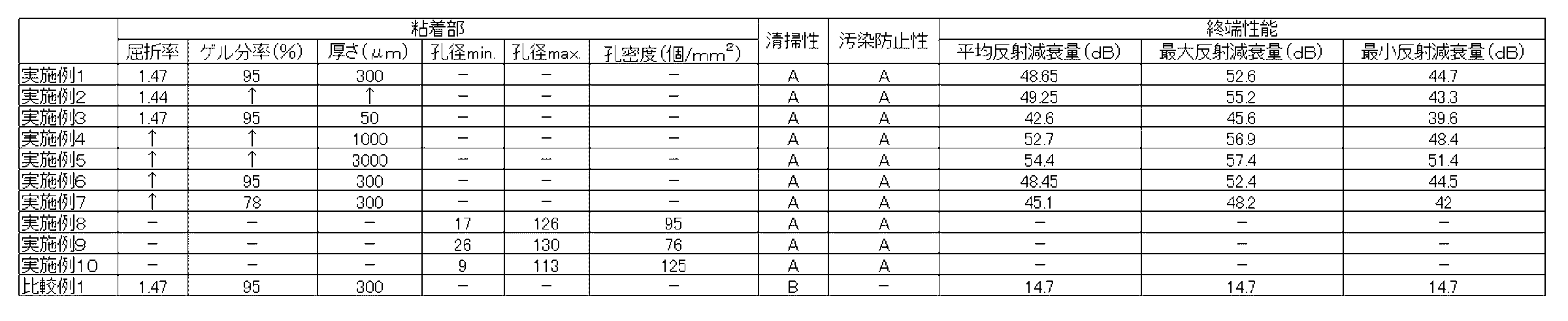
<評価結果>
すべての実施例で、清掃性(ゴミ取り性)と光接続端末先端面への汚染防止性で良好な結果が得られた。又、粘着部の厚さが、厚い方が、終端性能が高いことが明らかとなった。又、筒状部の材質をABS樹脂に変更した実施例6では、表中の性能では差異はないが、ABS樹脂はPE樹脂に比べ硬いため、光接続端末の脱離において相対的に操作性が悪い(抜き差しがし辛い)ことが明らかとなった。
又、樹脂発泡体を粘着部とした実施例8~10では、終端性は見られなかった。
一方比較例では、粘着部に当接しないため清掃能力は発揮できず、又、終端性能は著しく低いことが明らかとなった。
以上から、本発明による保護キャップの有用性が理解できる。
すべての実施例で、清掃性(ゴミ取り性)と光接続端末先端面への汚染防止性で良好な結果が得られた。又、粘着部の厚さが、厚い方が、終端性能が高いことが明らかとなった。又、筒状部の材質をABS樹脂に変更した実施例6では、表中の性能では差異はないが、ABS樹脂はPE樹脂に比べ硬いため、光接続端末の脱離において相対的に操作性が悪い(抜き差しがし辛い)ことが明らかとなった。
又、樹脂発泡体を粘着部とした実施例8~10では、終端性は見られなかった。
一方比較例では、粘着部に当接しないため清掃能力は発揮できず、又、終端性能は著しく低いことが明らかとなった。
以上から、本発明による保護キャップの有用性が理解できる。
100、101 光接続端末
111 光接続端末の先端面
112 可動レバー
113 爪部(第1の係止部)
114 挿入部
200、300、400、500 保護キャップ
210、410、510 キャップ部
310 蓋部
211、311、411、511 筒状部
220、320、420、520 底部(光吸収部)
230、330、430、530 粘着部
401 差込口
402 ガイド溝
403 凸部構造(凹部構造)
404 逃がし構造
111 光接続端末の先端面
112 可動レバー
113 爪部(第1の係止部)
114 挿入部
200、300、400、500 保護キャップ
210、410、510 キャップ部
310 蓋部
211、311、411、511 筒状部
220、320、420、520 底部(光吸収部)
230、330、430、530 粘着部
401 差込口
402 ガイド溝
403 凸部構造(凹部構造)
404 逃がし構造
Claims (12)
- 光ファイバ端末部に組み付けられる光接続端末を保護可能な保護キャップであって、
1方の端部が前記光接続端末を挿嵌可能な筒状部と前記筒状部の他方の端部に設けられた底部とからなるキャップ部と、
前記キャップ部内部に設けられており、且つ、前記光接続端末が前記筒状部を介して前記キャップ部内部に挿嵌された際、挿嵌された前記光接続端末の先端が当接可能な位置に配されている粘着部と、
を有する保護キャップ。 - 光ファイバ端末部に組み付けられる光接続端末を保護可能な保護キャップであって、
前記光接続端末を挿嵌可能な筒状部と、
前記筒状部が表面に設けられており、且つ、前記筒状部に前記光接続端末が挿嵌された際、前記光接続端末が前記筒状部を越えて内部まで貫通可能な貫通孔が設けられているケース部と、
前記ケース部内部に設けられており、且つ、前記光接続端末が前記貫通孔を介して前記ケース部内部に挿嵌された際、挿嵌された前記光接続端末の先端が当接可能な位置に配されている粘着部と
を有する保護キャップ。 - 前記ケース部は、前記筒状部が表面に設けられている蓋部と、前記粘着部が設けられている底部と、に分離可能である、請求項2に記載の保護キャップ。
- 複数の光接続端末及び/又は異なる形状の光接続端末の挿嵌用である、請求項2又は3に記載の保護キャップ。
- 前記筒状部は、柔軟成型樹脂からなる、請求項1~4のいずれか一項記載の保護キャップ。
- 前記柔軟成型樹脂が、ポリエチレン及び/又はポリプロピレンである、請求項5に記載の保護キャップ。
- 前記保護キャップは、
第1の係止部を有する光接続端末に用いられ、
第2の係止部を有する前記筒状部を含み、
前記光接続端末が前記筒状部に挿嵌される際、
前記光接続端末の先端と、前記粘着部とが、当接する位置において、
前記筒状部の第2の係止部と、
前記光接続端末の第1の係止部とが、
相互に係止することを特徴とする、
請求項1~4のいずれか一項に記載の保護キャップ。 - 前記粘着部は、連続気泡構造を有する樹脂発泡体を含む、請求項1~7のいずれか一項に記載の保護キャップ。
- 前記粘着部は、さらに基材を含む、請求項8記載の保護キャップ。
- 前記保護キャップは、
前記キャップ部、又は、前記ケース部に設けられており、且つ、前記光接続端末の先端と前記粘着部とを当接状態にして前記光接続端末に取り付けられた光ファイバから発光させたときに光終端性を発揮する光吸収部を、さらに有する、請求項1~7のいずれか一項に記載の保護キャップ。 - 前記粘着部の材質が透明であり、且つ、屈折率が1.43~1.55である、請求項10記載の保護キャップ。
- 前記粘着部の材質が、アクリル系粘着剤である、請求項10又は11に記載の保護キャップ。
Applications Claiming Priority (2)
| Application Number | Priority Date | Filing Date | Title |
|---|---|---|---|
| JP2017090144A JP2020109426A (ja) | 2017-04-28 | 2017-04-28 | 保護キャップ |
| JP2017-090144 | 2017-04-28 |
Publications (1)
| Publication Number | Publication Date |
|---|---|
| WO2018199331A1 true WO2018199331A1 (ja) | 2018-11-01 |
Family
ID=63918467
Family Applications (1)
| Application Number | Title | Priority Date | Filing Date |
|---|---|---|---|
| PCT/JP2018/017322 Ceased WO2018199331A1 (ja) | 2017-04-28 | 2018-04-27 | 保護キャップ |
Country Status (2)
| Country | Link |
|---|---|
| JP (1) | JP2020109426A (ja) |
| WO (1) | WO2018199331A1 (ja) |
Cited By (3)
| Publication number | Priority date | Publication date | Assignee | Title |
|---|---|---|---|---|
| WO2022066226A1 (en) * | 2020-09-22 | 2022-03-31 | Clearfield Inc. | Dustcap with built-in cleaner |
| US11681108B2 (en) | 2020-09-22 | 2023-06-20 | Clearfield, Inc. | Dustcap with built-in cleaner |
| US12474531B2 (en) | 2020-09-22 | 2025-11-18 | Clearfield, Inc. | Adapter dustcap with built-in cleaner |
Citations (7)
| Publication number | Priority date | Publication date | Assignee | Title |
|---|---|---|---|---|
| JP2002219421A (ja) * | 2001-01-25 | 2002-08-06 | Fujikura Ltd | 光コネクタ端面清掃具および光コネクタ端面清掃方法 |
| JP2004012625A (ja) * | 2002-06-04 | 2004-01-15 | Fujikura Ltd | 光コネクタのキャップ装着構造 |
| JP2006235502A (ja) * | 2005-02-28 | 2006-09-07 | Sanwa Denki Kogyo Co Ltd | 光プラグ用フェルールの保護キャップ |
| JP2009069385A (ja) * | 2007-09-12 | 2009-04-02 | Okano Electric Wire Co Ltd | コネクタキャップ、対照システム |
| WO2015017170A1 (en) * | 2013-07-31 | 2015-02-05 | Corning Optical Communications LLC | Fiber optic connector assembly with particle-collecting cover |
| JP2016175061A (ja) * | 2015-03-18 | 2016-10-06 | 株式会社巴川製紙所 | 端面クリーナ |
| US20160349460A1 (en) * | 2015-05-29 | 2016-12-01 | Corning Optical Communications LLC | Fiber optic cable assemblies with cap apparatuses for sealing optical fiber connectors and associated methods |
-
2017
- 2017-04-28 JP JP2017090144A patent/JP2020109426A/ja active Pending
-
2018
- 2018-04-27 WO PCT/JP2018/017322 patent/WO2018199331A1/ja not_active Ceased
Patent Citations (7)
| Publication number | Priority date | Publication date | Assignee | Title |
|---|---|---|---|---|
| JP2002219421A (ja) * | 2001-01-25 | 2002-08-06 | Fujikura Ltd | 光コネクタ端面清掃具および光コネクタ端面清掃方法 |
| JP2004012625A (ja) * | 2002-06-04 | 2004-01-15 | Fujikura Ltd | 光コネクタのキャップ装着構造 |
| JP2006235502A (ja) * | 2005-02-28 | 2006-09-07 | Sanwa Denki Kogyo Co Ltd | 光プラグ用フェルールの保護キャップ |
| JP2009069385A (ja) * | 2007-09-12 | 2009-04-02 | Okano Electric Wire Co Ltd | コネクタキャップ、対照システム |
| WO2015017170A1 (en) * | 2013-07-31 | 2015-02-05 | Corning Optical Communications LLC | Fiber optic connector assembly with particle-collecting cover |
| JP2016175061A (ja) * | 2015-03-18 | 2016-10-06 | 株式会社巴川製紙所 | 端面クリーナ |
| US20160349460A1 (en) * | 2015-05-29 | 2016-12-01 | Corning Optical Communications LLC | Fiber optic cable assemblies with cap apparatuses for sealing optical fiber connectors and associated methods |
Cited By (7)
| Publication number | Priority date | Publication date | Assignee | Title |
|---|---|---|---|---|
| WO2022066226A1 (en) * | 2020-09-22 | 2022-03-31 | Clearfield Inc. | Dustcap with built-in cleaner |
| US11422314B2 (en) | 2020-09-22 | 2022-08-23 | Clearfield, Inc. | Dustcap with built-in cleaner |
| US11675139B2 (en) | 2020-09-22 | 2023-06-13 | Clearfield, Inc. | Dust cap with built-in cleaner |
| US11681108B2 (en) | 2020-09-22 | 2023-06-20 | Clearfield, Inc. | Dustcap with built-in cleaner |
| US12007609B2 (en) | 2020-09-22 | 2024-06-11 | Clearfield, Inc. | Dustcap with built-in cleaner |
| US12287516B2 (en) | 2020-09-22 | 2025-04-29 | Clearfield, Inc. | Dustcap with built-in cleaner |
| US12474531B2 (en) | 2020-09-22 | 2025-11-18 | Clearfield, Inc. | Adapter dustcap with built-in cleaner |
Also Published As
| Publication number | Publication date |
|---|---|
| JP2020109426A (ja) | 2020-07-16 |
Similar Documents
| Publication | Publication Date | Title |
|---|---|---|
| US10739531B2 (en) | Connector cleaning tool | |
| WO2018199331A1 (ja) | 保護キャップ | |
| US7422375B2 (en) | Optical connection structure and optical connection method | |
| KR102713528B1 (ko) | 반사 방지 필름, 편광판, 커버 유리, 화상 표시 장치, 및 반사 방지 필름의 제조 방법 | |
| EP2951631B1 (en) | Fiber optic connector with fiber end protection | |
| CN109716172B (zh) | 高折射率纳米复合物 | |
| KR101750568B1 (ko) | 광 확산 감압 접착제 | |
| JP2008180799A (ja) | 光コネクタクリーナ | |
| FR3058410A1 (fr) | Fibre optique | |
| CN101226260A (zh) | 光连接器 | |
| HK1210861A1 (en) | Display device, process for manufacturing same, and transparent resin filler | |
| CN101284977A (zh) | 光学功能性薄膜用粘着剂和光学功能性薄膜及其制备方法 | |
| JP6767170B2 (ja) | 活性エネルギー線硬化性組成物 | |
| CN111440574B (zh) | 一种粘着剂组合物及一种应用于切割滤光片的减粘胶带 | |
| JPWO2016059727A1 (ja) | 光ファイバ心線及び光ファイバテープ心線 | |
| WO2015017170A1 (en) | Fiber optic connector assembly with particle-collecting cover | |
| EP2296024A1 (en) | Optical transmission medium, ferrule, optical termination connector, optical structure and optical apparatus | |
| JP6698104B2 (ja) | 光学部材、及び、重合体層 | |
| JPWO2009125806A1 (ja) | エネルギー線硬化性層用樹脂組成物および貫通孔形成用シート | |
| JP2016061794A (ja) | 反射防止フィルム、偏光板、カバーガラス、画像表示装置、及び反射防止フィルムの製造方法 | |
| EP2267499B1 (en) | Rubber member, adhesive connecting member and optical connecting structure | |
| JP2007093647A (ja) | 光学接続構造及び光学接続方法 | |
| JP2007225722A (ja) | 光コネクタ | |
| CN114456327B (zh) | 光固化性树脂组合物、固化物及层叠体 | |
| KR101007559B1 (ko) | 액정 디스플레이 패널의 박형화 방법 |
Legal Events
| Date | Code | Title | Description |
|---|---|---|---|
| 121 | Ep: the epo has been informed by wipo that ep was designated in this application |
Ref document number: 18791006 Country of ref document: EP Kind code of ref document: A1 |
|
| NENP | Non-entry into the national phase |
Ref country code: DE |
|
| 122 | Ep: pct application non-entry in european phase |
Ref document number: 18791006 Country of ref document: EP Kind code of ref document: A1 |
|
| NENP | Non-entry into the national phase |
Ref country code: JP |