WO2018199165A1 - 空気浄化システム - Google Patents
空気浄化システム Download PDFInfo
- Publication number
- WO2018199165A1 WO2018199165A1 PCT/JP2018/016796 JP2018016796W WO2018199165A1 WO 2018199165 A1 WO2018199165 A1 WO 2018199165A1 JP 2018016796 W JP2018016796 W JP 2018016796W WO 2018199165 A1 WO2018199165 A1 WO 2018199165A1
- Authority
- WO
- WIPO (PCT)
- Prior art keywords
- space
- carbon dioxide
- air
- room
- water vapor
- Prior art date
- Legal status (The legal status is an assumption and is not a legal conclusion. Google has not performed a legal analysis and makes no representation as to the accuracy of the status listed.)
- Ceased
Links
Images

Classifications
-
- B—PERFORMING OPERATIONS; TRANSPORTING
- B01—PHYSICAL OR CHEMICAL PROCESSES OR APPARATUS IN GENERAL
- B01D—SEPARATION
- B01D53/00—Separation of gases or vapours; Recovering vapours of volatile solvents from gases; Chemical or biological purification of waste gases, e.g. engine exhaust gases, smoke, fumes, flue gases, aerosols
- B01D53/26—Drying gases or vapours
- B01D53/268—Drying gases or vapours by diffusion
-
- B—PERFORMING OPERATIONS; TRANSPORTING
- B01—PHYSICAL OR CHEMICAL PROCESSES OR APPARATUS IN GENERAL
- B01D—SEPARATION
- B01D53/00—Separation of gases or vapours; Recovering vapours of volatile solvents from gases; Chemical or biological purification of waste gases, e.g. engine exhaust gases, smoke, fumes, flue gases, aerosols
- B01D53/22—Separation of gases or vapours; Recovering vapours of volatile solvents from gases; Chemical or biological purification of waste gases, e.g. engine exhaust gases, smoke, fumes, flue gases, aerosols by diffusion
-
- B—PERFORMING OPERATIONS; TRANSPORTING
- B01—PHYSICAL OR CHEMICAL PROCESSES OR APPARATUS IN GENERAL
- B01D—SEPARATION
- B01D53/00—Separation of gases or vapours; Recovering vapours of volatile solvents from gases; Chemical or biological purification of waste gases, e.g. engine exhaust gases, smoke, fumes, flue gases, aerosols
- B01D53/22—Separation of gases or vapours; Recovering vapours of volatile solvents from gases; Chemical or biological purification of waste gases, e.g. engine exhaust gases, smoke, fumes, flue gases, aerosols by diffusion
- B01D2053/221—Devices
- B01D2053/223—Devices with hollow tubes
- B01D2053/224—Devices with hollow tubes with hollow fibres
-
- B—PERFORMING OPERATIONS; TRANSPORTING
- B01—PHYSICAL OR CHEMICAL PROCESSES OR APPARATUS IN GENERAL
- B01D—SEPARATION
- B01D2257/00—Components to be removed
- B01D2257/50—Carbon oxides
- B01D2257/504—Carbon dioxide
-
- B—PERFORMING OPERATIONS; TRANSPORTING
- B01—PHYSICAL OR CHEMICAL PROCESSES OR APPARATUS IN GENERAL
- B01D—SEPARATION
- B01D2257/00—Components to be removed
- B01D2257/80—Water
-
- B—PERFORMING OPERATIONS; TRANSPORTING
- B01—PHYSICAL OR CHEMICAL PROCESSES OR APPARATUS IN GENERAL
- B01D—SEPARATION
- B01D2258/00—Sources of waste gases
- B01D2258/06—Polluted air
-
- B—PERFORMING OPERATIONS; TRANSPORTING
- B01—PHYSICAL OR CHEMICAL PROCESSES OR APPARATUS IN GENERAL
- B01D—SEPARATION
- B01D2259/00—Type of treatment
- B01D2259/45—Gas separation or purification devices adapted for specific applications
- B01D2259/4508—Gas separation or purification devices adapted for specific applications for cleaning air in buildings
-
- B—PERFORMING OPERATIONS; TRANSPORTING
- B01—PHYSICAL OR CHEMICAL PROCESSES OR APPARATUS IN GENERAL
- B01D—SEPARATION
- B01D2259/00—Type of treatment
- B01D2259/45—Gas separation or purification devices adapted for specific applications
- B01D2259/4566—Gas separation or purification devices adapted for specific applications for use in transportation means
-
- B—PERFORMING OPERATIONS; TRANSPORTING
- B01—PHYSICAL OR CHEMICAL PROCESSES OR APPARATUS IN GENERAL
- B01D—SEPARATION
- B01D2259/00—Type of treatment
- B01D2259/45—Gas separation or purification devices adapted for specific applications
- B01D2259/4566—Gas separation or purification devices adapted for specific applications for use in transportation means
- B01D2259/4575—Gas separation or purification devices adapted for specific applications for use in transportation means in aeroplanes or space ships
-
- Y—GENERAL TAGGING OF NEW TECHNOLOGICAL DEVELOPMENTS; GENERAL TAGGING OF CROSS-SECTIONAL TECHNOLOGIES SPANNING OVER SEVERAL SECTIONS OF THE IPC; TECHNICAL SUBJECTS COVERED BY FORMER USPC CROSS-REFERENCE ART COLLECTIONS [XRACs] AND DIGESTS
- Y02—TECHNOLOGIES OR APPLICATIONS FOR MITIGATION OR ADAPTATION AGAINST CLIMATE CHANGE
- Y02C—CAPTURE, STORAGE, SEQUESTRATION OR DISPOSAL OF GREENHOUSE GASES [GHG]
- Y02C20/00—Capture or disposal of greenhouse gases
- Y02C20/40—Capture or disposal of greenhouse gases of CO2
Definitions
- the present invention relates to an air purification system that purifies air in a room.
- Ventilation is carried out for rooms that accommodate people in buildings and transport equipment in order to suppress the increase in carbon dioxide concentration.
- the room is provided with an air conditioner for heating or cooling.
- the ventilation volume for suppressing the above-mentioned increase in carbon dioxide concentration is relatively large, so the load on the air conditioner increases accordingly.
- Patent Document 1 discloses an air purification system mounted on a railway vehicle.
- a carbon dioxide removing device is provided in a circulation path for circulating the air in the room.
- the carbon dioxide removing device includes a separation membrane that selectively permeates carbon dioxide.
- the carbon dioxide removing device has a permeation side in order to give a pressure difference between the circulation path side of the separation membrane (one of the spaces partitioned by the separation membrane) and the permeation side (the other of the spaces partitioned by the separation membrane).
- a vacuum pump for evacuating is connected.
- the pressure on the permeation side of the separation membrane is set to about 20 kPa, and a pressure difference of about 80 kPa is generated between the circulation path side and the permeation side of the separation membrane, so that carbon dioxide in the circulated air is reduced. It is described that it selectively permeates the separation membrane.
- the partial pressure of carbon dioxide in the air is about 0.1 kPa when the carbon dioxide concentration is 1000 ppm. Therefore, the pressure of 20 kPa is considerably higher than the partial pressure of carbon dioxide in the air, and if the separation membrane selectively permeates only carbon dioxide, the partial pressure of carbon dioxide on the permeate side immediately increases.
- some separation membranes selectively allow not only carbon dioxide but also water vapor.
- the carbon dioxide permeability and water vapor permeability of the separation membrane are similar, if the total pressure on the permeate side is 20 kPa, the carbon dioxide partial pressure on the permeate side is higher than the carbon dioxide partial pressure in the air. Even in this case, the carbon dioxide partial pressure on the permeate side immediately increases, so the amount of carbon dioxide that permeates is extremely small, or a large amount of air is combined with carbon dioxide to obtain a realistic carbon dioxide permeation amount. The transmission becomes necessary and the device becomes unrealistic. That is, in the degree of vacuum described in the cited document 1, it is not realistic to remove carbon dioxide from the air in the room.
- an object of the present invention is to realize an air purification system capable of efficiently removing carbon dioxide using a separation membrane and a vacuum pump.
- an air purification system of the present invention is an air purification system for purifying air in a room, and includes a first space and a second space partitioned by a separation membrane that selectively transmits carbon dioxide.
- a carbon dioxide removing device including a space, a feed path for guiding air in the room to the first space, a return path for guiding clean air from which carbon dioxide has been removed from the first space to the room, and the second And a decompression pump that evacuates the second space so that the partial pressure of carbon dioxide in the space is lower than the partial pressure of carbon dioxide in the air in the room.
- the carbon dioxide partial pressure in the second space of the carbon dioxide removing device is lower than the carbon dioxide partial pressure in the first space, so that carbon dioxide continues to selectively permeate the separation membrane. Therefore, carbon dioxide can be efficiently removed from the air in the room.
- the separation membrane selectively permeates water vapor as well as carbon dioxide
- the vacuum pump is configured such that the total pressure in the second space is lower than the partial pressure of water vapor in the air in the room.
- the second space may be evacuated.
- the separation membrane selectively transmits only carbon dioxide, that is, when the second space is only carbon dioxide, the pressure in the second space is less than the partial pressure of carbon dioxide in the first space. Need to be evacuated. For example, when the carbon dioxide concentration in the room air is 1000 ppm, the pressure in the second space needs to be less than 0.1 kPa.
- the separation membrane selectively permeates not only carbon dioxide but also water vapor, since there is more water vapor than carbon dioxide in the room air, carbon dioxide also in the second space. The amount of water vapor can be increased. Therefore, if the total pressure in the second space is set to be lower than the partial pressure of water vapor in the first space, it is possible to suppress an increase in the partial pressure of carbon dioxide in the second space, which is necessary for the actual scale of the apparatus. It is possible to obtain a carbon permeation amount.
- the air purification system may further include a water vapor supply device that supplies water vapor to the second space such that a water vapor partial pressure in the second space is substantially equal to a water vapor partial pressure in the first space. .
- a water vapor supply device that supplies water vapor to the second space such that a water vapor partial pressure in the second space is substantially equal to a water vapor partial pressure in the first space.
- carbon dioxide can be efficiently removed using a separation membrane and a vacuum pump.
- FIG. 1 is a schematic configuration diagram of an air purification system according to a first embodiment of the present invention. It is a schematic block diagram of the air purification system which concerns on 2nd Embodiment of this invention.
- FIG. 1 shows an air purification system 1A according to the first embodiment of the present invention.
- This air purification system 1A purifies the air in the room 2 that accommodates people.
- the room 2 may be a room of a building such as an office building, or may be a room of transportation equipment such as a railway vehicle or an aircraft (so-called cabin).
- the room 2 may be a space station, a submarine, a disaster evacuation facility, or the like.
- the air purification system 1A includes a carbon dioxide removing device 4.
- the carbon dioxide removing device 4 is arranged outside the room 2, but the carbon dioxide removing device 4 may be arranged inside the room 2.
- the carbon dioxide removing device 4 includes a first space 41 and a second space 42 partitioned by a separation membrane 43.
- the separation membrane 43 selectively transmits carbon dioxide from the first space 41 toward the second space 42.
- the separation membrane 43 selectively transmits water vapor as well as carbon dioxide.
- the carbon dioxide permeability and water vapor permeability of the separation membrane 43 are desirably 1000 times or more of the nitrogen permeability and the oxygen permeability.
- the separation membrane 43 is a hollow fiber membrane.
- many hollow fiber membranes may comprise one membrane module, and the carbon dioxide removal apparatus 4 may contain many membrane modules.
- the separation membrane 43 is a hollow fiber membrane, the inside of the hollow fiber membrane is the first space 41 and the outside of the hollow fiber membrane is the second space 42.
- Air in the room 2 is guided to the first space 41 of the carbon dioxide removal device 4 through the feed path 51, and clean air from which carbon dioxide has been removed is guided to the room 2 through the return path 52 from the first space 41. It is burned.
- the blower 53 is provided in the feed path 51, but the blower 53 may be provided in the return path 52.
- the blower 53 may be a blower or a fan (the same applies to a blower described later).
- a suction path 61 is connected to the second space 42 of the carbon dioxide removal device 4.
- the downstream end of the suction path 61 is open to the atmosphere.
- a vacuum pump 62 is provided in the suction path 61.
- the decompression pump 62 evacuates the second space 42 so that the partial pressure of carbon dioxide in the second space 42 is lower than the partial pressure of carbon dioxide in the air in the room 2.
- the carbon dioxide partial pressure is about 0.1 kPa.
- the separation membrane 43 transmits not only carbon dioxide but also water vapor, even if the total pressure in the second space 42 is about 1.0 kPa, the carbon dioxide partial pressure in the second space 42 is the first. It can be suppressed to less than the partial pressure of carbon dioxide in the space 41.
- the energy required for driving the decompression pump 62 can be reduced, although the size of the carbon dioxide removing device 4 is increased.
- the total pressure in the second space 42 which is a target value for controlling the decompression pump 62, may be, for example, 0.5 kPa or less. Alternatively, the total pressure in the second space 42 may be changed according to the relative humidity in the room 2.
- the room 2 is provided with an air conditioner 3 for heating and cooling.
- the room 2 is connected to a first ventilation path 71 and a second ventilation path 72.
- Blowers 73 and 74 are provided in the first ventilation path 71 and the second ventilation path 72, respectively.
- the carbon dioxide partial pressure in the second space 42 of the carbon dioxide removing device 4 is lower than the carbon dioxide partial pressure in the first space 41, so carbon dioxide is Continue to selectively permeate the separation membrane 43. Therefore, carbon dioxide can be efficiently removed from the air in the room 2.
- the separation membrane 43 selectively transmits water vapor as well as carbon dioxide.
- the separation membrane 43 selectively transmits only carbon dioxide, that is, when the second space 42 is only carbon dioxide, the second space 42 is less than the partial pressure of carbon dioxide in the first space 41. It is necessary to evacuate the vacuum so that For example, when the carbon dioxide concentration in the room air is 1000 ppm, the pressure in the second space 42 needs to be less than 0.1 kPa.
- the separation membrane 43 selectively permeates not only carbon dioxide but also water vapor as in the present embodiment, since there is more water vapor than carbon dioxide in the room air, Even in the second space 42, the amount of water vapor can be made larger than that of carbon dioxide.
- the total pressure in the second space 42 is set to be lower than the partial pressure of water vapor in the first space 41, it is possible to suppress an increase in the partial pressure of carbon dioxide in the second space 42, which is necessary depending on a realistic apparatus scale. It becomes possible to obtain the carbon dioxide permeation amount.
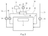
- FIG. 2 shows an air purification system 1B according to the second embodiment of the present invention.
- the same components as those in the first embodiment are denoted by the same reference numerals, and a duplicate description is omitted.
- the air purification system 1B of the present embodiment is obtained by adding a water vapor supply device 8 to the air purification system 1A of the first embodiment.
- the water vapor supply device 8 supplies water vapor to the second space 42 such that the water vapor partial pressure in the second space 42 of the carbon dioxide removing device 4 is substantially equal to the water vapor partial pressure in the first space 41.
- the water vapor partial pressure in the second space 42 of the carbon dioxide removing device 4 is preferably maintained within a range of ⁇ 10% of the water vapor partial pressure in the first space 41.
- water vapor is prevented from passing through the separation membrane 43 from the first space 41 toward the second space 42. Accordingly, since the suction amount of the decompression pump 62 is reduced, the load on the decompression pump 62 can be reduced.
- the present invention is not limited to the above-described embodiments, and various modifications can be made without departing from the gist of the present invention.
- the air conditioner 3 is not necessarily provided in the room 2.
- the component that selectively permeates through the separation membrane 43 together with carbon dioxide is not necessarily water vapor, and may be nitrogen or oxygen. That is, the separation membrane 43 may selectively transmit not only carbon dioxide but also nitrogen or oxygen.
- the separation membrane 43 may selectively transmit only carbon dioxide.
- the decompression pump 62 may evacuate the second space 42 so that the pressure in the second space 42 is less than 0.1 kPa.
Landscapes
- Chemical & Material Sciences (AREA)
- Engineering & Computer Science (AREA)
- Analytical Chemistry (AREA)
- General Chemical & Material Sciences (AREA)
- Oil, Petroleum & Natural Gas (AREA)
- Chemical Kinetics & Catalysis (AREA)
- Separation Using Semi-Permeable Membranes (AREA)
- Gas Separation By Absorption (AREA)
Abstract
部屋内の空気を浄化する空気浄化システムは、二酸化炭素を選択的に透過させる分離膜で仕切られた第1空間および第2空間を含む二酸化炭素除去装置と、部屋内の空気を第1空間へ導く送り路と、二酸化炭素が除去された清浄空気を第1空間から部屋へ導く戻り路と、第2空間の二酸化炭素分圧が、部屋内の空気中の二酸化炭素分圧よりも低くなるように第2空間を真空引きする減圧ポンプと、を備える。
Description
本発明は、部屋内の空気を浄化する空気浄化システムに関する。
建物や輸送機器などにおける人を収容する部屋に対しては、二酸化炭素濃度の上昇を抑えるために換気が行われる。また、部屋には、暖房または冷房を行う空調装置が設けられる。
上記の二酸化炭素濃度の上昇を抑えるための換気量は比較的に大きいために、その分、空調装置の負荷が高くなる。近年では、空調装置の負荷を低減するために、部屋内の空気から二酸化炭素を除去して当該空気を浄化することが提案されている。
例えば、特許文献1には、鉄道車両に搭載される空気浄化システムが開示されている。この空気浄化システムでは、部屋内の空気を循環させる循環路に二酸化炭素除去装置が設けられている。二酸化炭素除去装置は、二酸化炭素を選択的に透過させる分離膜を含む。また、二酸化炭素除去装置には、分離膜の循環路側(分離膜で仕切られる空間の一方)と透過側(分離膜で仕切られる空間の他方)との間に圧力差を与えるために、透過側を真空引きする減圧ポンプが接続されている。
特許文献1には、分離膜の透過側の圧力を20kPa程度として、分離膜の循環路側と透過側との間に80kPa程度の圧力差を生じさせることで、循環される空気中の二酸化炭素が分離膜を選択的に透過すると記載されている。
しかしながら、空気中の二酸化炭素分圧は、二酸化炭素濃度が1000ppmの場合で約0.1kPaである。従って、20kPaという圧力は空気中の二酸化炭素分圧よりもかなり高く、仮に分離膜が二酸化炭素のみを選択的に透過させる場合には、透過側の二酸化炭素分圧が即座に上昇してしまうため、透過する二酸化炭素は極めて少なくなる、もしくは優位な二酸化炭素透過量を得るためには、透過側の二酸化炭素分圧を低く維持するために二酸化炭素以外のガス成分も同時に大量に透過させる必要があり減圧ポンプの消費電力が過大となる。
一方、分離膜としては、二酸化炭素だけでなく水蒸気をも選択的に透過させるものもある。しかしながら、分離膜の二酸化炭素透過度と水蒸気透過度とが同程度の場合でも、透過側の全圧が20kPaであれば、透過側の二酸化炭素分圧は空気中の二酸化炭素分圧よりも高く、この場合でもやはり透過側の二酸化炭素分圧が即座に上昇してしまうため、透過する二酸化炭素は極めて少なくなる、もしくは現実的な二酸化炭素透過量を得るために大量の空気を二酸化炭素と合わせて透過させることが必要となり装置が非現実的なものとなる。すなわち、引用文献1に記載された程度の真空度においては、部屋内の空気から二酸化炭素を除去することは現実的ではない。
そこで、本発明は、分離膜および減圧ポンプを用いて二酸化炭素を効率的に除去することができる空気浄化システムを実現することを目的とする。
前記課題を解決するために、本発明の空気浄化システムは、部屋内の空気を浄化する空気浄化システムであって、二酸化炭素を選択的に透過させる分離膜で仕切られた第1空間および第2空間を含む二酸化炭素除去装置と、前記部屋内の空気を前記第1空間へ導く送り路と、二酸化炭素が除去された清浄空気を前記第1空間から前記部屋へ導く戻り路と、前記第2空間の二酸化炭素分圧が、前記部屋内の空気中の二酸化炭素分圧よりも低くなるように前記第2空間を真空引きする減圧ポンプと、を備える、ことを特徴とする。
上記の構成によれば、二酸化炭素除去装置の第2空間の二酸化炭素分圧が第1空間の二酸化炭素分圧よりも低くなるため、二酸化炭素が分離膜を選択的に透過し続ける。従って、部屋内の空気から二酸化炭素を効率的に除去することができる。
前記分離膜は、二酸化炭素だけでなく水蒸気をも選択的に透過させるものであり、前記減圧ポンプは、前記第2空間の全圧が前記部屋内の空気中の水蒸気分圧よりも低くなるように、前記第2空間を真空引きしてもよい。分離膜が二酸化炭素のみを選択的に透過させるものである場合、すなわち、第2空間内が二酸化炭素のみである場合には、第2空間を第1空間の二酸化炭素分圧未満の圧力となるように真空引きする必要がある。例えば、部屋内空気中の二酸化炭素濃度が1000ppmである場合には、第2空間の圧力を0.1kPa未満とする必要がある。これに対し、分離膜が二酸化炭素だけでなく水蒸気をも選択的に透過さるものであれば、部屋内空気中には二酸化炭素よりも多くの水蒸気が存在するため、第2空間内でも二酸化炭素よりも水蒸気の量を多くすることができる。従って、第2空間の全圧を第1空間の水蒸気分圧未満に設定すれば、第2空間の二酸化炭素分圧の増加を抑制することが可能となり、現実的な装置規模によって必要となる二酸化炭素透過量を得ることが可能となる。
上記の空気浄化システムは、前記第2空間の水蒸気分圧が前記第1空間の水蒸気分圧と実質的に等しくなるように前記第2空間に水蒸気を供給する水蒸気供給装置をさらに備えてもよい。この構成によれば、水蒸気が第1空間から第2空間へ向かって分離膜を透過することが抑制される。従って、減圧ポンプの吸引量が減少するため、減圧ポンプの負荷を低減することができる。
本発明によれば、分離膜および減圧ポンプを用いて二酸化炭素を効率的に除去することができる。
(第1実施形態)
図1に、本発明の第1実施形態に係る空気浄化システム1Aを示す。この空気浄化システム1Aは、人を収容する部屋2内の空気を浄化するものである。
図1に、本発明の第1実施形態に係る空気浄化システム1Aを示す。この空気浄化システム1Aは、人を収容する部屋2内の空気を浄化するものである。
例えば、部屋2は、オフィスビルのような建物の部屋であってもよいし、鉄道車両や航空機のような輸送機器の部屋(いわゆるキャビン)であってもよい。あるいは、部屋2は、宇宙ステーション、潜水船、災害時避難設備などの部屋であってもよい。
空気浄化システム1Aは、二酸化炭素除去装置4を含む。図例では、二酸化炭素除去装置4が部屋2外に配置されているが、二酸化炭素除去装置4は部屋2内に配置されてもよい。
二酸化炭素除去装置4は、分離膜43で仕切られた第1空間41および第2空間42を含む。分離膜43は、第1空間41から第2空間42へ向かって、二酸化炭素を選択的に透過させる。本実施形態では、分離膜43が、二酸化炭素だけでなく水蒸気をも選択的に透過させる。
分離膜43の二酸化炭素透過度および水蒸気透過度は、窒素透過度および酸素透過度の1000倍以上であることが望ましい。各成分についての透過度は、下記式で表される。
m=K×A×ΔP
m:特定成分の透過速度[mol/sec]
K:特定成分の透過度[mol/(m2・sec・Pa)]
A:分離膜の面積[m2]
ΔP:分離膜の両側での特定成分の分圧差[Pa]
m=K×A×ΔP
m:特定成分の透過速度[mol/sec]
K:特定成分の透過度[mol/(m2・sec・Pa)]
A:分離膜の面積[m2]
ΔP:分離膜の両側での特定成分の分圧差[Pa]
例えば、分離膜43は、中空糸膜である。この場合、多数の中空糸膜が1つの膜モジュールを構成し、二酸化炭素除去装置4が多数の膜モジュールを含んでもよい。分離膜43が中空糸膜である場合、中空糸膜の内側が第1空間41、中空糸膜の外側が第2空間42である。
二酸化炭素除去装置4の第1空間41へは、送り路51を通じて部屋2内の空気が導かれ、第1空間41からは、戻り路52を通じて二酸化炭素が除去された清浄空気が部屋2へ導かれる。本実施形態では、送り路51に送風機53が設けられているが、送風機53は戻り路52に設けられてもよい。送風機53は、ブロアであってもよいしファンであってもよい(後述する送風機も同様)。
二酸化炭素除去装置4の第2空間42には、吸引路61が接続されている。吸引路61の下流端は、大気中に開口している。吸引路61には、減圧ポンプ62が設けられている。
減圧ポンプ62は、第2空間42の二酸化炭素分圧が部屋2内の空気中の二酸化炭素分圧よりも低くなるように第2空間42を真空引きする。例えば、部屋2内の空気が25℃で大気圧であり、部屋2内の空気中の二酸化炭素濃度が1000ppmである場合、二酸化炭素分圧は約0.1kPaである。本実施形態では、分離膜43が二酸化炭素だけでなく水蒸気をも透過させるため、第2空間42の全圧が1.0kPa程度であっても、第2空間42の二酸化炭素分圧を第1空間41の二酸化炭素分圧未満に抑えることができる。
例えば、第2空間42の全圧が0.1kPaの場合には、減圧ポンプ62の駆動に非常に大きなエネルギーが必要になる。しかし、第2空間42の全圧が1.0kPa程度であれば、二酸化炭素除去装置4のサイズは大きくなるものの、減圧ポンプ62の駆動に必要なエネルギーを少なくすることができる。
部屋2内の空気が25℃で大気圧である場合、部屋2内の空気中の水蒸気分圧は、部屋2内の相対湿度が20%の場合に0.6kPa、相対湿度が80%の場合に2.5kPaである。従って、減圧ポンプ62の制御の目標値である第2空間42の全圧は、例えば0.5kPa以下としてもよい。あるいは、第2空間42の全圧は、部屋2内の相対湿度に応じて変動させてもよい。
部屋2には、暖房および冷房を行う空調装置3が設けられている。また、部屋2には、第1換気路71および第2換気路72が接続されている。
部屋2へは、第1換気路71を通じて大気中から外気が供給され、部屋2内の空気は、第2換気路72を通じて大気中へ排出される。第1換気路71および第2換気路72には、それぞれ送風機73,74が設けられている。
以上説明したように、本実施形態の空気浄化システム1Aでは、二酸化炭素除去装置4の第2空間42の二酸化炭素分圧が第1空間41の二酸化炭素分圧よりも低くなるため、二酸化炭素が分離膜43を選択的に透過し続ける。従って、部屋2内の空気から二酸化炭素を効率的に除去することができる。
また、本実施形態では、分離膜43が二酸化炭素だけでなく水蒸気をも選択的に透過させる。分離膜43が二酸化炭素のみを選択的に透過させるものである場合、すなわち、第2空間42内が二酸化炭素のみである場合には、第2空間42を第1空間41の二酸化炭素分圧未満の圧力となるように真空引きする必要がある。例えば、部屋内空気中の二酸化炭素濃度が1000ppmである場合には、第2空間42の圧力を0.1kPa未満とする必要がある。これに対し、本実施形態のように分離膜43が二酸化炭素だけでなく水蒸気をも選択的に透過さるものであれば、部屋内空気中には二酸化炭素よりも多くの水蒸気が存在するため、第2空間42内でも二酸化炭素よりも水蒸気の量を多くすることができる。従って、第2空間42の全圧を第1空間41の水蒸気分圧未満に設定すれば、第2空間42の二酸化炭素分圧の増加を抑制することが可能となり、現実的な装置規模によって必要となる二酸化炭素透過量を得ることが可能となる。
(第2実施形態)
図2に、本発明の第2実施形態に係る空気浄化システム1Bを示す。なお、本実施形態において、第1実施形態と同一構成要素には同一符号を付し、重複した説明は省略する。
図2に、本発明の第2実施形態に係る空気浄化システム1Bを示す。なお、本実施形態において、第1実施形態と同一構成要素には同一符号を付し、重複した説明は省略する。
本実施形態の空気浄化システム1Bは、第1実施形態の空気浄化システム1Aに水蒸気供給装置8を加えたものである。水蒸気供給装置8は、二酸化炭素除去装置4の第2空間42の水蒸気分圧が第1空間41の水蒸気分圧と実質的に等しくなるように、第2空間42に水蒸気を供給する。例えば、二酸化炭素除去装置4の第2空間42の水蒸気分圧は、第1空間41の水蒸気分圧の±10%の範囲内に保たれることが望ましい。
本実施形態では、水蒸気が第1空間41から第2空間42へ向かって分離膜43を透過することが抑制される。従って、減圧ポンプ62の吸引量が減少するため、減圧ポンプ62の負荷を低減することができる。
(その他の実施形態)
本発明は上述した実施形態に限定されるものではなく、本発明の要旨を逸脱しない範囲で種々の変形が可能である。例えば、部屋2には、必ずしも空調装置3が設けられている必要はない。
本発明は上述した実施形態に限定されるものではなく、本発明の要旨を逸脱しない範囲で種々の変形が可能である。例えば、部屋2には、必ずしも空調装置3が設けられている必要はない。
また、二酸化炭素と共に分離膜43を選択的に透過する成分は、必ずしも水蒸気である必要はなく、窒素または酸素であってもよい。つまり、分離膜43は、二酸化炭素だけでなく窒素または酸素をも選択的に透過させるものであってもよい。
あるいは、分離膜43は、二酸化炭素のみを選択的に透過させるものであってもよい。この場合、減圧ポンプ62は、第2空間42の圧力が0.1kPa未満となるように、第2空間42を真空引きすればよい。
1A,1B 空気浄化システム
2 部屋
4 二酸化炭素除去装置
41 第1空間
42 第2空間
43 分離膜
51 送り路
52 戻り路
62 減圧ポンプ
8 水蒸気供給装置
2 部屋
4 二酸化炭素除去装置
41 第1空間
42 第2空間
43 分離膜
51 送り路
52 戻り路
62 減圧ポンプ
8 水蒸気供給装置
Claims (3)
- 部屋内の空気を浄化する空気浄化システムであって、
二酸化炭素を選択的に透過させる分離膜で仕切られた第1空間および第2空間を含む二酸化炭素除去装置と、
前記部屋内の空気を前記第1空間へ導く送り路と、
二酸化炭素が除去された清浄空気を前記第1空間から前記部屋へ導く戻り路と、
前記第2空間の二酸化炭素分圧が、前記部屋内の空気中の二酸化炭素分圧よりも低くなるように前記第2空間を真空引きする減圧ポンプと、
を備える、空気浄化システム。 - 前記分離膜は、二酸化炭素だけでなく水蒸気をも選択的に透過させるものであり、
前記減圧ポンプは、前記第2空間の全圧が前記部屋内の空気中の水蒸気分圧よりも低くなるように、前記第2空間を真空引きする、請求項1に記載の空気浄化システム。 - 前記第2空間の水蒸気分圧が前記第1空間の水蒸気分圧と実質的に等しくなるように前記第2空間に水蒸気を供給する水蒸気供給装置をさらに備える、請求項2に記載の空気浄化システム。
Priority Applications (2)
| Application Number | Priority Date | Filing Date | Title |
|---|---|---|---|
| CN201880025114.8A CN110536737A (zh) | 2017-04-27 | 2018-04-25 | 空气净化系统 |
| US16/608,913 US20200246749A1 (en) | 2017-04-27 | 2018-04-25 | Air purifying system |
Applications Claiming Priority (2)
| Application Number | Priority Date | Filing Date | Title |
|---|---|---|---|
| JP2017-087808 | 2017-04-27 | ||
| JP2017087808A JP6877229B2 (ja) | 2017-04-27 | 2017-04-27 | 空気浄化システム |
Publications (1)
| Publication Number | Publication Date |
|---|---|
| WO2018199165A1 true WO2018199165A1 (ja) | 2018-11-01 |
Family
ID=63919845
Family Applications (1)
| Application Number | Title | Priority Date | Filing Date |
|---|---|---|---|
| PCT/JP2018/016796 Ceased WO2018199165A1 (ja) | 2017-04-27 | 2018-04-25 | 空気浄化システム |
Country Status (4)
| Country | Link |
|---|---|
| US (1) | US20200246749A1 (ja) |
| JP (1) | JP6877229B2 (ja) |
| CN (1) | CN110536737A (ja) |
| WO (1) | WO2018199165A1 (ja) |
Cited By (2)
| Publication number | Priority date | Publication date | Assignee | Title |
|---|---|---|---|---|
| CN109276194A (zh) * | 2018-11-28 | 2019-01-29 | 贵州工程应用技术学院 | 一种智能工业清洁机器人 |
| EP3922344A4 (en) * | 2019-02-05 | 2022-10-26 | Kawasaki Jukogyo Kabushiki Kaisha | AIR PURIFICATION SYSTEM |
Families Citing this family (5)
| Publication number | Priority date | Publication date | Assignee | Title |
|---|---|---|---|---|
| JP2021102198A (ja) * | 2019-12-25 | 2021-07-15 | 株式会社クラレ | 二酸化炭素分離デバイス、空気清浄機、エアーコンディショナ、及び二酸化炭素濃縮装置 |
| JP7773852B2 (ja) * | 2020-11-10 | 2025-11-20 | 日産自動車株式会社 | 車両用空調方法及び車両用空調システム |
| KR102556881B1 (ko) * | 2021-06-03 | 2023-07-19 | 화인클린(주) | 미세먼지와 이산화탄소 제거를 위한 공기청정기 |
| US20220401878A1 (en) * | 2021-06-21 | 2022-12-22 | Air Products And Chemicals, Inc. | Reducing energy consumption for marine and offshore membrane applications |
| WO2026059604A1 (en) * | 2024-09-11 | 2026-03-19 | W. L. Gore & Associates, Inc. | Dehumidifying systems and methods |
Citations (5)
| Publication number | Priority date | Publication date | Assignee | Title |
|---|---|---|---|---|
| WO2014065387A1 (ja) * | 2012-10-22 | 2014-05-01 | 住友化学株式会社 | 共重合体及び炭酸ガス分離膜 |
| JP5738704B2 (ja) * | 2011-07-26 | 2015-06-24 | 富士フイルム株式会社 | 二酸化炭素分離装置および二酸化炭素分離方法 |
| JP5743639B2 (ja) * | 2011-03-29 | 2015-07-01 | 新日鉄住金エンジニアリング株式会社 | 二酸化炭素ガス分離システム |
| JP2015192927A (ja) * | 2014-03-31 | 2015-11-05 | Tdk株式会社 | ガス分離膜およびガス分離装置 |
| JP2017006820A (ja) * | 2015-06-18 | 2017-01-12 | 住友化学株式会社 | 二酸化炭素分離方法及び二酸化炭素分離装置 |
Family Cites Families (3)
| Publication number | Priority date | Publication date | Assignee | Title |
|---|---|---|---|---|
| US5799652A (en) * | 1995-05-22 | 1998-09-01 | Hypoxico Inc. | Hypoxic room system and equipment for Hypoxic training and therapy at standard atmospheric pressure |
| JP2003025991A (ja) * | 2001-07-13 | 2003-01-29 | Hitachi Ltd | 換気装置 |
| CN102438728A (zh) * | 2009-03-26 | 2012-05-02 | 依卡贝尔技术有限公司 | 用于分离气体的方法 |
-
2017
- 2017-04-27 JP JP2017087808A patent/JP6877229B2/ja active Active
-
2018
- 2018-04-25 CN CN201880025114.8A patent/CN110536737A/zh active Pending
- 2018-04-25 WO PCT/JP2018/016796 patent/WO2018199165A1/ja not_active Ceased
- 2018-04-25 US US16/608,913 patent/US20200246749A1/en not_active Abandoned
Patent Citations (5)
| Publication number | Priority date | Publication date | Assignee | Title |
|---|---|---|---|---|
| JP5743639B2 (ja) * | 2011-03-29 | 2015-07-01 | 新日鉄住金エンジニアリング株式会社 | 二酸化炭素ガス分離システム |
| JP5738704B2 (ja) * | 2011-07-26 | 2015-06-24 | 富士フイルム株式会社 | 二酸化炭素分離装置および二酸化炭素分離方法 |
| WO2014065387A1 (ja) * | 2012-10-22 | 2014-05-01 | 住友化学株式会社 | 共重合体及び炭酸ガス分離膜 |
| JP2015192927A (ja) * | 2014-03-31 | 2015-11-05 | Tdk株式会社 | ガス分離膜およびガス分離装置 |
| JP2017006820A (ja) * | 2015-06-18 | 2017-01-12 | 住友化学株式会社 | 二酸化炭素分離方法及び二酸化炭素分離装置 |
Cited By (3)
| Publication number | Priority date | Publication date | Assignee | Title |
|---|---|---|---|---|
| CN109276194A (zh) * | 2018-11-28 | 2019-01-29 | 贵州工程应用技术学院 | 一种智能工业清洁机器人 |
| EP3922344A4 (en) * | 2019-02-05 | 2022-10-26 | Kawasaki Jukogyo Kabushiki Kaisha | AIR PURIFICATION SYSTEM |
| US11872521B2 (en) | 2019-02-05 | 2024-01-16 | Kawasaki Jukogyo Kabushiki Kaisha | Air purifying system |
Also Published As
| Publication number | Publication date |
|---|---|
| US20200246749A1 (en) | 2020-08-06 |
| CN110536737A (zh) | 2019-12-03 |
| JP6877229B2 (ja) | 2021-05-26 |
| JP2018183750A (ja) | 2018-11-22 |
Similar Documents
| Publication | Publication Date | Title |
|---|---|---|
| WO2018199165A1 (ja) | 空気浄化システム | |
| WO2018199164A1 (ja) | 空気浄化システム | |
| US20080127821A1 (en) | Method and device for reducing the carbon dioxide concentration in air | |
| CN104941394B (zh) | 气体分离系统及富化气体的制造方法 | |
| CN113218023B (zh) | 空气组成调节装置 | |
| MX2024014574A (es) | Sistema de captura directa de aire con panel movil de alto rendimiento | |
| US9981221B2 (en) | Gas separation system and enriched gas production method | |
| JP6953764B2 (ja) | バイオガス濃縮システムおよびバイオガス濃縮方法 | |
| JP6415159B2 (ja) | 有機溶剤精製システム及び方法 | |
| WO2019065884A1 (ja) | 空気組成調節装置 | |
| JP6164682B2 (ja) | ガス分離装置及びそれを用いた酸性ガスの分離方法 | |
| EP4108315A1 (en) | Reducing energy consumption for marine and offshore membrane applications | |
| JP2018502303A5 (ja) | ||
| JP6609386B1 (ja) | 空気浄化システム | |
| JP2002263433A (ja) | 保存庫内の気体組成の制御方法と保存庫 | |
| JP2022076664A (ja) | 車両用空調方法及び車両用空調システム | |
| JP4810748B2 (ja) | 除湿システム | |
| JP2003089508A (ja) | オゾン発生システム | |
| KR101514449B1 (ko) | 육불화황(sf6) 농축 및 열분해장치 | |
| WO2024190846A1 (ja) | ガス分離システム及び混合ガスの分離方法 | |
| JP2025001702A (ja) | 二酸化炭素分離システム及び二酸化炭素分離方法 | |
| JPH0730927B2 (ja) | 空気調和機 | |
| JP6746434B2 (ja) | 空気調和装置 | |
| JPH05293328A (ja) | 可燃性有機蒸気含有空気の処理方法 | |
| CN110559850A (zh) | 一种空气净化器 |
Legal Events
| Date | Code | Title | Description |
|---|---|---|---|
| 121 | Ep: the epo has been informed by wipo that ep was designated in this application |
Ref document number: 18790124 Country of ref document: EP Kind code of ref document: A1 |
|
| NENP | Non-entry into the national phase |
Ref country code: DE |
|
| 122 | Ep: pct application non-entry in european phase |
Ref document number: 18790124 Country of ref document: EP Kind code of ref document: A1 |