WO2018199058A1 - 体温計測装置 - Google Patents
体温計測装置 Download PDFInfo
- Publication number
- WO2018199058A1 WO2018199058A1 PCT/JP2018/016535 JP2018016535W WO2018199058A1 WO 2018199058 A1 WO2018199058 A1 WO 2018199058A1 JP 2018016535 W JP2018016535 W JP 2018016535W WO 2018199058 A1 WO2018199058 A1 WO 2018199058A1
- Authority
- WO
- WIPO (PCT)
- Prior art keywords
- body temperature
- temperature data
- temperature
- equilibrium state
- measuring device
- Prior art date
Links
Images


Classifications
-
- G—PHYSICS
- G16—INFORMATION AND COMMUNICATION TECHNOLOGY [ICT] SPECIALLY ADAPTED FOR SPECIFIC APPLICATION FIELDS
- G16H—HEALTHCARE INFORMATICS, i.e. INFORMATION AND COMMUNICATION TECHNOLOGY [ICT] SPECIALLY ADAPTED FOR THE HANDLING OR PROCESSING OF MEDICAL OR HEALTHCARE DATA
- G16H40/00—ICT specially adapted for the management or administration of healthcare resources or facilities; ICT specially adapted for the management or operation of medical equipment or devices
- G16H40/60—ICT specially adapted for the management or administration of healthcare resources or facilities; ICT specially adapted for the management or operation of medical equipment or devices for the operation of medical equipment or devices
- G16H40/63—ICT specially adapted for the management or administration of healthcare resources or facilities; ICT specially adapted for the management or operation of medical equipment or devices for the operation of medical equipment or devices for local operation
-
- A—HUMAN NECESSITIES
- A61—MEDICAL OR VETERINARY SCIENCE; HYGIENE
- A61B—DIAGNOSIS; SURGERY; IDENTIFICATION
- A61B5/00—Measuring for diagnostic purposes; Identification of persons
- A61B5/0002—Remote monitoring of patients using telemetry, e.g. transmission of vital signals via a communication network
- A61B5/0004—Remote monitoring of patients using telemetry, e.g. transmission of vital signals via a communication network characterised by the type of physiological signal transmitted
- A61B5/0008—Temperature signals
-
- A—HUMAN NECESSITIES
- A61—MEDICAL OR VETERINARY SCIENCE; HYGIENE
- A61B—DIAGNOSIS; SURGERY; IDENTIFICATION
- A61B5/00—Measuring for diagnostic purposes; Identification of persons
- A61B5/01—Measuring temperature of body parts ; Diagnostic temperature sensing, e.g. for malignant or inflamed tissue
-
- A—HUMAN NECESSITIES
- A61—MEDICAL OR VETERINARY SCIENCE; HYGIENE
- A61B—DIAGNOSIS; SURGERY; IDENTIFICATION
- A61B5/00—Measuring for diagnostic purposes; Identification of persons
- A61B5/72—Signal processing specially adapted for physiological signals or for diagnostic purposes
- A61B5/7235—Details of waveform analysis
- A61B5/7264—Classification of physiological signals or data, e.g. using neural networks, statistical classifiers, expert systems or fuzzy systems
-
- A—HUMAN NECESSITIES
- A61—MEDICAL OR VETERINARY SCIENCE; HYGIENE
- A61B—DIAGNOSIS; SURGERY; IDENTIFICATION
- A61B5/00—Measuring for diagnostic purposes; Identification of persons
- A61B5/74—Details of notification to user or communication with user or patient ; user input means
- A61B5/746—Alarms related to a physiological condition, e.g. details of setting alarm thresholds or avoiding false alarms
-
- G—PHYSICS
- G01—MEASURING; TESTING
- G01K—MEASURING TEMPERATURE; MEASURING QUANTITY OF HEAT; THERMALLY-SENSITIVE ELEMENTS NOT OTHERWISE PROVIDED FOR
- G01K13/00—Thermometers specially adapted for specific purposes
- G01K13/20—Clinical contact thermometers for use with humans or animals
-
- G—PHYSICS
- G01—MEASURING; TESTING
- G01K—MEASURING TEMPERATURE; MEASURING QUANTITY OF HEAT; THERMALLY-SENSITIVE ELEMENTS NOT OTHERWISE PROVIDED FOR
- G01K7/00—Measuring temperature based on the use of electric or magnetic elements directly sensitive to heat ; Power supply therefor, e.g. using thermoelectric elements
- G01K7/16—Measuring temperature based on the use of electric or magnetic elements directly sensitive to heat ; Power supply therefor, e.g. using thermoelectric elements using resistive elements
-
- G—PHYSICS
- G01—MEASURING; TESTING
- G01K—MEASURING TEMPERATURE; MEASURING QUANTITY OF HEAT; THERMALLY-SENSITIVE ELEMENTS NOT OTHERWISE PROVIDED FOR
- G01K7/00—Measuring temperature based on the use of electric or magnetic elements directly sensitive to heat ; Power supply therefor, e.g. using thermoelectric elements
- G01K7/42—Circuits effecting compensation of thermal inertia; Circuits for predicting the stationary value of a temperature
- G01K7/427—Temperature calculation based on spatial modeling, e.g. spatial inter- or extrapolation
-
- G—PHYSICS
- G16—INFORMATION AND COMMUNICATION TECHNOLOGY [ICT] SPECIALLY ADAPTED FOR SPECIFIC APPLICATION FIELDS
- G16H—HEALTHCARE INFORMATICS, i.e. INFORMATION AND COMMUNICATION TECHNOLOGY [ICT] SPECIALLY ADAPTED FOR THE HANDLING OR PROCESSING OF MEDICAL OR HEALTHCARE DATA
- G16H10/00—ICT specially adapted for the handling or processing of patient-related medical or healthcare data
- G16H10/60—ICT specially adapted for the handling or processing of patient-related medical or healthcare data for patient-specific data, e.g. for electronic patient records
-
- G—PHYSICS
- G16—INFORMATION AND COMMUNICATION TECHNOLOGY [ICT] SPECIALLY ADAPTED FOR SPECIFIC APPLICATION FIELDS
- G16H—HEALTHCARE INFORMATICS, i.e. INFORMATION AND COMMUNICATION TECHNOLOGY [ICT] SPECIALLY ADAPTED FOR THE HANDLING OR PROCESSING OF MEDICAL OR HEALTHCARE DATA
- G16H50/00—ICT specially adapted for medical diagnosis, medical simulation or medical data mining; ICT specially adapted for detecting, monitoring or modelling epidemics or pandemics
- G16H50/20—ICT specially adapted for medical diagnosis, medical simulation or medical data mining; ICT specially adapted for detecting, monitoring or modelling epidemics or pandemics for computer-aided diagnosis, e.g. based on medical expert systems
-
- A—HUMAN NECESSITIES
- A61—MEDICAL OR VETERINARY SCIENCE; HYGIENE
- A61B—DIAGNOSIS; SURGERY; IDENTIFICATION
- A61B2560/00—Constructional details of operational features of apparatus; Accessories for medical measuring apparatus
- A61B2560/02—Operational features
- A61B2560/0242—Operational features adapted to measure environmental factors, e.g. temperature, pollution
- A61B2560/0247—Operational features adapted to measure environmental factors, e.g. temperature, pollution for compensation or correction of the measured physiological value
- A61B2560/0252—Operational features adapted to measure environmental factors, e.g. temperature, pollution for compensation or correction of the measured physiological value using ambient temperature
-
- A—HUMAN NECESSITIES
- A61—MEDICAL OR VETERINARY SCIENCE; HYGIENE
- A61B—DIAGNOSIS; SURGERY; IDENTIFICATION
- A61B2562/00—Details of sensors; Constructional details of sensor housings or probes; Accessories for sensors
- A61B2562/02—Details of sensors specially adapted for in-vivo measurements
- A61B2562/0271—Thermal or temperature sensors
-
- A—HUMAN NECESSITIES
- A61—MEDICAL OR VETERINARY SCIENCE; HYGIENE
- A61B—DIAGNOSIS; SURGERY; IDENTIFICATION
- A61B5/00—Measuring for diagnostic purposes; Identification of persons
- A61B5/02—Detecting, measuring or recording pulse, heart rate, blood pressure or blood flow; Combined pulse/heart-rate/blood pressure determination; Evaluating a cardiovascular condition not otherwise provided for, e.g. using combinations of techniques provided for in this group with electrocardiography or electroauscultation; Heart catheters for measuring blood pressure
- A61B5/0205—Simultaneously evaluating both cardiovascular conditions and different types of body conditions, e.g. heart and respiratory condition
- A61B5/02055—Simultaneously evaluating both cardiovascular condition and temperature
-
- A—HUMAN NECESSITIES
- A61—MEDICAL OR VETERINARY SCIENCE; HYGIENE
- A61B—DIAGNOSIS; SURGERY; IDENTIFICATION
- A61B5/00—Measuring for diagnostic purposes; Identification of persons
- A61B5/72—Signal processing specially adapted for physiological signals or for diagnostic purposes
- A61B5/7221—Determining signal validity, reliability or quality
-
- Y—GENERAL TAGGING OF NEW TECHNOLOGICAL DEVELOPMENTS; GENERAL TAGGING OF CROSS-SECTIONAL TECHNOLOGIES SPANNING OVER SEVERAL SECTIONS OF THE IPC; TECHNICAL SUBJECTS COVERED BY FORMER USPC CROSS-REFERENCE ART COLLECTIONS [XRACs] AND DIGESTS
- Y02—TECHNOLOGIES OR APPLICATIONS FOR MITIGATION OR ADAPTATION AGAINST CLIMATE CHANGE
- Y02A—TECHNOLOGIES FOR ADAPTATION TO CLIMATE CHANGE
- Y02A90/00—Technologies having an indirect contribution to adaptation to climate change
- Y02A90/10—Information and communication technologies [ICT] supporting adaptation to climate change, e.g. for weather forecasting or climate simulation
Definitions
- the present invention relates to a body temperature measuring device, and more particularly to a body temperature measuring device that continuously measures body temperature (depth body temperature).
- Patent Document 1 discloses a wearable temperature measurement device that estimates body temperature such as mouth temperature based on time-series body surface temperature data (for example, body surface temperature data of a measured subject measured while sleeping). ing.
- the wearable temperature measuring device includes a body surface temperature detecting unit that detects the temperature of the body surface, an auxiliary body surface temperature detecting unit that auxiliaryly detects the temperature of the body surface affected by the outside air, And an outside air temperature detecting unit for detecting the outside air temperature, and an inverse calculation model is constructed by PLS regression analysis using a body surface temperature data group and body temperature measured in advance. And this wearing type temperature measuring device estimates a body temperature from the temperature data group which arranged the temperature detection data detected by each temperature detection part in time series using the inverse calculation model.
- the body temperature is estimated from the body surface temperature data group using the inverse calculation model, for example, it can be easily used even when performing the health care of the subject based on the daily body temperature. Can do. Furthermore, since the body temperature is estimated from body surface temperature detection data measured over several hours using an inverse calculation model, the influence of measurement fluctuations is suppressed compared to the case where body temperature such as mouth temperature is directly measured. be able to.
- the body surface temperature largely fluctuates due to disturbances such as outside air temperature. That is, for example, when a sudden temperature change occurs when moving from a warm room to a cold outdoors, the body surface temperature greatly fluctuates.
- body temperature is estimated using an inverse calculation model constructed by PLS regression analysis, but in principle, the influence of disturbances such as outside temperature is correctly corrected (compensated). Therefore, there is a possibility that the influence of disturbance cannot be properly eliminated.
- the wearable temperature measurement device described above uses an inverse calculation model to estimate body temperature from body surface temperature detection data measured over several hours, so it grasps heat generation in a relatively short time (span). There is a risk that it may be difficult to do or grasping may be delayed.
- the present invention has been made to solve the above problems, and is capable of appropriately eliminating the influence of disturbance and capable of grasping heat generation in a shorter time (span).
- the purpose is to provide.
- the body temperature measuring device includes a thermal detector, a temperature detection unit that is arranged so as to sandwich the thermal resistor, and has a plurality of temperature sensors that continuously detect temperature data, and the temperature detection unit is a thermal detector.
- An equilibrium state determination means for determining whether the temperature detection unit is in a thermal equilibrium state by the equilibrium state determination means, and the thermal data of the thermal resistor.
- body temperature acquisition means for acquiring body temperature data based on the resistance value.
- the body temperature measurement device it is determined whether or not the temperature detection unit (a plurality of temperature sensors) is in a thermal equilibrium state (a state in which there is no variation in heat flow), and the temperature detection unit is thermally detected.
- Body temperature data is acquired based on the temperature data detected when it is determined to be in an equilibrium state and the thermal resistance value of the thermal resistor. For this reason, for example, even if the temperature detector temporarily becomes non-equilibrium due to a sudden change in ambient temperature due to entering or leaving the room (disturbance), it has become non-equilibrium (being in an unequilibrium state) And inaccurate temperature data (noise) can be removed.
- noise temperature data in a non-equilibrium state
- a low-pass filter having a large time constant, for example.
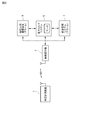
- FIG. 1 is a block diagram showing a functional configuration of the body temperature measuring device 1.
- FIG. 2 is a block diagram showing an overall configuration of a hospital system to which the body temperature measuring device 1 is applied.
- FIG. 3 is a diagram illustrating a configuration of the temperature detection unit 11 included in the body temperature measurement device 1.
- the body temperature measuring device 1 mainly acquires the body temperature based on the temperature detected by the temperature detector 11 (non-heated depth thermometer) 11 that is attached to the body surface and detects the temperature, and the temperature detector 11.
- a temperature information processing unit 50 is provided.
- the temperature detection unit 11 mainly includes a flexible substrate 110 and two sets of sensing units 11a and 11b.
- the temperature information processing unit 50 mainly includes an MCU 51, a wireless communication module 52, a battery 53, and a notification unit 54.
- the temperature detection unit 11 is attached to the user's body surface and detects the temperature of the user's body surface and the like. As described above, the temperature detection unit 11 includes two sets of sensing units 11a and 11b. One sensing unit 11a is mounted on a thermal resistor 115 having a predetermined thermal resistance value and, for example, a flexible substrate (film substrate) 110 having flexibility, and sandwiches the thermal resistor 115 from the thickness direction. A pair of temperature sensors, that is, a first temperature sensor 111 and a second temperature sensor 112. Note that each of the first temperature sensor 111 and the second temperature sensor 112 may be embedded in the thermal resistor 115, for example.
- the other sensing unit 11b is mounted on a thermal resistor 116 having a thermal resistance value different from that of the thermal resistor 115 and a flexible substrate (film substrate) 110, and is disposed so as to sandwich the thermal resistor 116 from the thickness direction.
- a pair of temperature sensors that is, a third temperature sensor 113 and a fourth temperature sensor 114 are configured. Each of the third temperature sensor 113 and the fourth temperature sensor 114 may be embedded in the thermal resistor 116, for example.
- each of the two sets of sensing units 11a and 11b includes a sheet-shaped heat insulating member 117 disposed so as to cover the second temperature sensor 112 and a sheet-shaped heat insulating member disposed so as to cover the fourth temperature sensor 114. A member 117 is further provided.
- the thermal resistors 115 and 116 are formed in a rectangular thin sheet shape having a predetermined thickness, for example.
- the shape of the thermal resistors 115 and 116 is not limited to a rectangle, and may be, for example, a circle.
- the thermal resistors 115 and 116 are formed of a heat insulating material such as a polyethylene foam or a urethane foam.
- the thermal resistors 115 and 116 have flexibility so as to follow the shape and movement of the body surface.
- the thickness of the thermal resistors 115 and 116 is preferably about 0.1 mm to several mm, for example.
- the thermal resistance value of the thermal resistor 115 is set to be different from the thermal resistance value of the thermal resistor 116.
- the thermal resistance values of the thermal resistors 115 and 116 can be adjusted, for example, by changing the thickness of the thermal resistors.
- thermal resistance RB can be canceled, and the body temperature (depth body temperature) can be obtained even if the thermal resistance RB of the human body is unknown. Therefore, since the deep body temperature can be acquired without assuming the thermal resistance RB of the human body, the deep body temperature can be acquired with higher accuracy even when the thermal resistance RB of each user is different. A method for canceling the thermal resistance RB of the human body will be described later.
- the temperature sensors 111 to 114 for example, a thermistor or a resistance temperature detector whose resistance value changes with temperature is preferably used.
- the temperature sensors 111 to 114 preferably have a heat capacity as small as possible from the viewpoint of improving responsiveness. Therefore, for example, a chip thermistor is preferably used as the temperature sensors 111 to 114.
- Each of the four temperature sensors 111 to 114 is electrically connected to the temperature information processing unit 50 (MCU 51) via printed wiring, and an electric signal (voltage value) corresponding to the temperature is transmitted to the temperature information processing unit 50 ( Read by MCU 51).
- the temperature information processing unit 50 mainly includes an MCU (Micro Control Unit) 51, a wireless communication module 52, a battery 53, a notification unit 54, and the like.
- the four temperature sensors 111 to 114 are connected to the temperature information processing unit 50 (MCU 51), and the detection signals (temperature data) output from the temperature sensors 111 to 114 are the temperature information processing unit 50. (MCU 51).
- the temperature information processing unit 50 includes a thermal resistance value of the thermal resistor 115 that constitutes one sensing unit 11a, a detected temperature of the first temperature sensor 111, a detected temperature of the second temperature sensor 112, and the other sensing unit 11b.
- the body temperature depth body temperature
- the body temperature is obtained based on the thermal resistance value of the thermal resistor 116 constituting the above, the detected temperature of the third temperature sensor 113, and the detected temperature of the fourth temperature sensor 114. Details will be described later. Further, when determining the body temperature (deep body temperature), for example, instead of the thermal resistance values of the thermal resistor 115 and the thermal resistor 116, the heat capacity, specific heat, density, shape, etc. of the thermal resistor 115 and the thermal resistor 116, etc. Such physical property values may be used.
- the temperature information processing unit 50 can appropriately eliminate the influence of disturbance and has a function of grasping heat generation in a shorter time (span). Therefore, the temperature information processing unit 50 functionally includes an equilibrium state determination unit 511, a body temperature acquisition unit 513, a personal characteristic information acquisition unit 514, a normal heat range setting unit 515, a heat generation determination unit 516, and a storage unit (memory) 517. ing.
- a program stored in a ROM or the like is executed by the MCU 51, whereby an equilibrium state determination unit 511, a body temperature acquisition unit 513, a personal characteristic information acquisition unit 514, a normal heat range setting unit 515, a heat generation determination The function of the unit 516 is realized.
- the equilibrium state determination unit 511 determines whether or not the temperature detection unit 11 (temperature sensors 111 to 114) is in a thermal equilibrium state (a state in which there is no variation in heat flow) using an equilibrium state discriminant. That is, the equilibrium state determination unit 511 functions as an equilibrium state determination unit described in the claims. More specifically, the equilibrium state determination unit 511 determines whether or not the temperature detection unit 11 is in a thermal equilibrium state using the following equilibrium state discriminant (1).
- the temperature data detected by the first temperature sensor 111 is T1
- the temperature data detected by the second temperature sensor 112 is T2
- the temperature data detected by the third temperature sensor 113 is T3
- the fourth temperature sensor 114 is When the detected temperature data is T4, the equilibrium state determination unit 511 indicates that the temperature detection unit 11 (temperature sensors 111 to 114) is in a thermal equilibrium state when the equilibrium state discriminant (1) is satisfied. It is determined that On the other hand, if the equilibrium state discriminant (1) is not satisfied, the equilibrium state determination unit 511 determines that the temperature detection unit 11 (temperature sensors 111 to 114) is not in a thermal equilibrium state (is in an unbalanced state). judge. T3-T4> T1-T2, T3> T1 (1)
- the temperature Ta in the hospital can be obtained from the electronic medical chart system 6 (or the infection management system 7), for example, the following equilibrium state discriminants (2), (3), and (4) are further taken into consideration. It may be determined whether the unit 11 (four temperature sensors 111 to 114) is in a thermal equilibrium state. In this case, when all of the equilibrium state discriminants (2), (3), and (4) are satisfied in addition to the above-described equilibrium state discriminant (1), the temperature detector 11 (temperature sensors 111 to 114) is heated. Is determined to be in an equilibrium state. On the other hand, if any of the equilibrium state discriminants (1) to (4) or all of the equilibrium state discriminants (1) to (4) are not satisfied, the temperature detector 11 (temperature sensors 111 to 114) is heated.
- the temperature detector 11 (temperature sensors 111 to 114) is used by using the following equilibrium state discriminants (5) to (8). It may be determined whether or not is in a thermally equilibrium state. In this case, when at least one of the following equilibrium state discriminants (5) to (8) is satisfied, the temperature detector 11 (temperature sensors 111 to 114) is thermally activated. It is determined to be in an equilibrium state. On the other hand, when all of the following equilibrium state discriminants (5) to (8) are not satisfied, the temperature detection unit 11 (temperature sensors 111 to 114) is not in a thermal equilibrium state (non-equilibrium state). Determined.
- ⁇ T3 ⁇ a (Where a is a predetermined value such as 0.2 (° C./min), for example) ⁇ T1 ⁇ a (6) (Where a is a predetermined value such as 0.2 (° C./min), for example) ⁇ T3 ⁇ T4 (7) ⁇ T1 ⁇ T2 (8)
- the determination result by the equilibrium state determination unit 511 (information on whether or not the temperature detection unit 11 is in a thermal equilibrium state) is output to the body temperature acquisition unit 513.
- the body temperature acquisition unit 513 includes the thermal resistance value RpA of the thermal resistor 115 stored in advance, the detected temperature T1 of the first temperature sensor 111, the detected temperature T2 of the second temperature sensor 112, and the heat stored in advance. Based on the thermal resistance value RpB of the resistor 116, the detected temperature T3 of the third temperature sensor 113, and the detected temperature T4 of the fourth temperature sensor 114, body temperature data (depth body temperature) is obtained. In particular, the body temperature acquisition unit 513 acquires body temperature data based on the temperature data detected when the temperature detection unit 11 is determined to be in a thermal equilibrium state. That is, the body temperature acquisition unit 513 functions as body temperature acquisition means described in the claims.
- the body temperature acquisition unit 513 first performs temperature compensation calculation on the detected temperature data, and calculates body temperature data candidates (or correction values). Next, the body temperature acquisition unit 513 removes body temperature data candidates (or correction values) obtained from the temperature data detected in the non-equilibrium state based on the determination result of the thermal equilibrium state, and acquires normal body temperature data. To do. This will be described in more detail below.
- the body temperature acquisition unit 513 uses the following equations (9) and (10) to erase the unknown thermal resistance RB by comparing the heat flow of two systems having different thermal resistances (thermal resistances), and the unknown thermal resistance RB
- the body temperature data candidate Tb of the user (human body) who has is calculated (estimated).
- RpA and RpB are thermal resistances (known) of the thermal resistors 115 and 116.
- body temperature data candidates can be calculated (estimated) by one sensing unit 11a (or 11b). More specifically, the body temperature data candidate of the human body is Tb, the detected temperature of the first temperature sensor 111 is T1, the detected temperature of the second temperature sensor 112 is T2, and the equivalent thermal resistance from the deep part of the human body to the body surface is represented by RB.
- the equivalent thermal resistance in the thickness direction of the thermal resistor 115 is RpA
- the thermal resistance RB of the human body is known, or by setting, for example, a general (standard) thermal resistance value as the thermal resistance RB of the human body, the temperature T1 detected by the first temperature sensor 111, and The deep body temperature Tb can be obtained from the temperature T2 detected by the second temperature sensor 112.
- the body temperature acquisition unit 513 removes the body temperature data candidate obtained from the temperature data detected when there is a thermal non-equilibrium state based on the above-described thermal equilibrium state determination result, and puts it in a thermal equilibrium state.
- the body temperature data candidate obtained from the temperature data detected at a certain time is acquired as normal body temperature data.
- FIG. 5 shows an example of the body temperature data candidate (heat flow compensation calculation result) before performing the equilibrium state determination (that is, before removing the body temperature data candidate obtained from the temperature data detected in the non-equilibrium state).
- FIG. 6 shows an example of body temperature data (heat flow compensation calculation result) after performing the equilibrium state determination (that is, after removing the body temperature data candidate obtained from the temperature data detected in the non-equilibrium state).
- the horizontal axis represents time, and the vertical axis represents temperature (° C.).
- body temperature data candidates noise obtained from temperature data (inaccurate temperature data) detected when the temperature detector 11 is in a non-equilibrium state are removed.
- Body temperature data (deep body temperature Tb) acquired by the body temperature acquisition unit 513 is output to the heat generation determination unit 516, the wireless communication module 52, and the storage unit 517.
- the personal identification information acquisition unit 514 acquires personal characteristic information (for example, age, sex, height, weight, etc.) of the user. That is, the personal identification information acquisition unit 514 functions as acquisition means described in the claims.
- the personal characteristic information of the user can be acquired from the electronic medical chart system 6 or the like via wireless communication (wireless communication device 5 and wireless communication module 52), for example. Further, for example, an input I / F such as a touch panel may be provided and information may be input from the input I / F.
- the personal characteristic information of the user acquired by the personal identification information acquisition unit 514 is stored in the storage unit 517 and is output to the normal heat range setting unit 515 as necessary.
- the normal heat range setting unit 515 sets the normal heat range of the user (the expected value range of normal heat). That is, the normal heat range setting unit 515 functions as the setting means described in the claims. More specifically, the normal heat range setting unit 515 sets the normal heat range of the user (expected value range of normal heat) in association with the time of the day (for each time). Further, the normal heat range setting unit 515 sets the normal heat range of the user (expected value range of normal heat) from statistical data belonging to the same category as the user based on the personal characteristic information of the user.
- the normal heat range setting unit 515 calculates, for example, “Ave ⁇ 3 ⁇ ” from statistical data (for example, average value Ave and standard deviation ⁇ ) of people belonging to the same category (for example, the same age and sex) as the user. Is set as the normal heat range (expected value range of normal heat).
- the statistical data (average value and standard deviation) is acquired from the electronic medical chart system 6 or the like in advance via wireless communication (wireless communication device 5 and wireless communication module 52) and stored in the storage unit 517, for example. Keep it.
- the function of the normal heat range setting unit 515 may be provided on the electronic medical chart system 6 side, and the user's normal heat range (expected value range of normal heat) may be set on the electronic medical record system 6 side.
- the normal heat range setting unit 515 learns the user's body temperature data acquired in the past and stored in the storage unit 517, and sets (or corrects) the normal heat range of the user in consideration of the learned value. It is preferable to do.
- the normal heat usually fluctuates by 1 ° C. or more within a day, varies depending on individual characteristics such as age and sex, and further varies depending on individuals.
- a normal heat range (expected value range of normal heat) is set in consideration of daily fluctuations and personal characteristics such as age and sex, and a learning value (learning result) is used. Individual differences are corrected.
- the user's normal heat range (expected value range of normal heat) set by the normal heat range setting unit 515 is output to the heat generation determination unit 516.
- the fever determining unit 516 determines (detects) whether or not the body temperature is within the normal heat range (whether or not the body temperature is abnormal). That is, the heat generation determination unit 516 functions as a determination unit described in the claims. The determination result by the heat generation determination unit 516 (information on whether or not the user's body temperature is within the normal heat range) is output to the notification unit 54.
- the notification unit 54 has, for example, an LCD display and a buzzer (or speaker), and when the body temperature data falls outside the normal heat range, the user and / or the administrator (in this embodiment, a doctor, a nurse, etc.) ) Is notified that the body temperature data is out of the normal heat range.
- the notification unit 54 outputs, for example, a warning display or a warning sound (alarm or beep sound) when the body temperature is out of the normal heat range (Ave ⁇ 3 ⁇ ). That is, the notification unit 54 functions as a notification unit described in the claims.
- the notification unit 54 preferably transmits notification information (warning information) to the electronic medical record system 6 via wireless communication (the wireless communication module 52 and the wireless communication device 5).
- the electronic medical record system 6 displays warning indications and warning sounds for the portable terminal 8 (for nurses) and the infection management system 7 (for doctors) that are electrically connected. Request output of (alarm or beep). Thereby, a nurse or a doctor can be made to recognize a user's (patient) body temperature abnormality.
- the notification unit 54 transmits the notification information (warning information) to the portable terminal 8 (for nurses) or the infection management system 7 (for doctors) via wireless communication (wireless communication module 52 and wireless communication device 5). It is also possible to send a request directly and output a warning display or warning sound (alarm or beep sound).
- the notification unit 54 when the body temperature data satisfies a predetermined disease management condition, the notification unit 54 notifies the user and / or administrator (such as a doctor or nurse in this embodiment) that the body temperature data has a predetermined disease management. Notify that the condition is satisfied.
- the notification unit 54 outputs, for example, a warning display or a warning sound (alarm or beep sound) when detecting a body temperature above a certain level or an increase in body temperature above a certain level. Also in this case, as described above, it is preferable to transmit notification information (warning information) to the electronic medical chart system 6 via wireless communication (the wireless communication module 52 and the wireless communication device 5).
- the notification unit 54 notifies that there is a measurement abnormality when body temperature data cannot be acquired for a predetermined time or longer. For example, the notification unit 54 outputs an alarm as a measurement abnormality when body temperature data cannot be acquired for 30 minutes or more. Also in this case, as described above, it is preferable to transmit notification information (warning information) to the electronic medical chart system 6 via wireless communication (the wireless communication module 52 and the wireless communication device 5).
- the wireless communication module 52 transmits the acquired body temperature data and the above-described notification information (warning information) to the external wireless communication device 5 (electronic medical chart system 6) and the like.
- the wireless communication module 52 receives the above-described personal characteristic information of the user, statistical data (average value and standard deviation) for setting the normal heat range, and the like from the wireless communication device 5 (electronic medical chart system 6).
- the wireless communication module 52 transmits and receives the information using, for example, BT (Bluetooth (registered trademark)).
- the temperature information processing unit 50 contains a thin battery 53 therein.
- the battery 53 supplies power to the MCU 51, the wireless communication module 52, and the like.
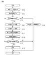
- FIG. 4 is a flowchart showing a processing procedure of a deep body temperature measurement process and a body temperature abnormality detection process performed by the body temperature measuring apparatus 1.
- the process shown in FIG. 4 is repeatedly executed mainly at a predetermined timing by the temperature information processing unit 50.
- step S100 temperature data detected by each temperature sensor 111 to 114 is read.
- step S102 heat flow compensation calculation is performed on the read temperature data using the heat flow compensation calculation formulas (9) and (10), and body temperature data candidates are calculated (see FIG. 5). Since the heat flow compensation calculation is as described above, detailed description thereof is omitted here.
- step S104 using the above-described equilibrium state discriminant (1), whether or not the temperature detection unit 11 (temperature sensors 111 to 114) is in a thermally equilibrium state (a state in which the heat flow rate does not vary). Judgment is made. If it is determined that the thermal equilibrium state is present, the process proceeds to step S106. On the other hand, when it is determined that the thermal equilibrium state is not established, the process proceeds to step S108.
- step S106 the body temperature data candidates calculated in step S102 are acquired and output as normal body temperature data (see FIG. 6). Thereafter, the process proceeds to step S110. On the other hand, in step S108, the body temperature data candidate calculated in step S102 is removed (discarded). Thereafter, the process is temporarily exited.
- step S110 the body temperature data acquired in step S106 is displayed.
- step S112 personal characteristic information (for example, age, gender, height, weight, etc.) of the user is acquired from the electronic medical record system 6 of the hospital via wireless communication.
- personal characteristic information for example, age, gender, height, weight, etc.
- step S114 the personal characteristics of the user and the categories (for example, the same age, sex, etc.) are associated with the personal characteristics from the normal range (statistical data) stored in advance in association with the personal characteristics.
- the stored normal heat range for each time is acquired.
- step S116 it is determined whether or not the body temperature is within the normal heat range at the same time. If the body temperature is within the normal heat range, the process is temporarily exited (for example, without displaying a warning display or a warning sound). On the other hand, when the body temperature is outside the normal heat range, the process proceeds to step S118.
- step S118 it is notified that the body temperature data is outside the normal heat range. That is, for example, a warning display or a warning sound indicating that the body temperature data is outside the normal heat range is output.
- the temperature detection unit 11 (four temperature sensors 111 to 114) is in a thermal equilibrium state using the equilibrium state discriminant (1). Is determined, and body temperature data is acquired based on the temperature data detected when it is determined that the temperature detector 11 is in a thermal equilibrium state. For this reason, for example, even if the temperature detection unit 11 is temporarily in a non-equilibrium state due to a sudden change in ambient temperature (disturbance) caused by entering or leaving the room, the temperature detection unit 11 has become a non-equilibrium state (being a non-equilibrium state). ) And inaccurate body temperature data candidates / temperature data (noise) can be removed.
- noise body temperature data candidate / temperature data in a non-equilibrium state
- noise body temperature data candidate / temperature data in a non-equilibrium state
- personal characteristic information for example, age, sex, height, weight, etc.
- the normal heat range expected value range of normal heat
- the normal heat range is individually set from statistical data that matches the personal characteristics of the user.
- the normal heat range of the user (expected value range of normal heat) is set for each time in association with the time of the day. For this reason, for example, daily fluctuations in body temperature can be taken into account, and it becomes possible to more accurately detect fever outside the normal heat range. As a result, the patient's fever can be detected accurately and early in the hospital, for example, day or night.
- the user's body temperature data acquired in the past is learned, and the user's normal heat range (expected value range of normal heat) is set (or corrected) in consideration of the learned value learned. . Therefore, it is possible to further increase the certainty of the normal heat range for each user due to the learning effect.
- the user and / or the manager when the body temperature data is out of the normal heat range, the user and / or the manager (doctor or nurse) is notified that the body temperature data is out of the normal heat range. . Therefore, when it is detected that the body temperature data is out of the normal heat range, it is possible to make the user and / or the administrator recognize that fact (that is, the fact that heat is generated). As a result, for example, the patient's fever can be grasped accurately and early in the hospital regardless of day or night, and countermeasure activities such as treatment can be started early. In particular, if you want to measure the body temperature of hospitalized patients continuously and notify you of a fever alarm, you do not need special procedures such as inserting a thermometer under the tongue or armpit of the hospitalized patient. It can function continuously for a long time just by sticking to the executive.
- the fact that the body temperature data satisfies the predetermined disease management condition for the user and / or the administrator (doctor or nurse). Is notified. Therefore, for example, when detecting a body temperature or a rise in body temperature above a certain level, the user and / or the administrator can recognize that fact.
- a user when body temperature data is not acquired for a predetermined time (for example, 30 minutes) or longer, it is notified that the measurement is abnormal (for example, a warning display or a warning sound (alarm) is output). Therefore, a user (doctor or nurse) can recognize measurement abnormality at an early stage.
- a predetermined time for example, 30 minutes
- a warning display or a warning sound (alarm) is output. Therefore, a user (doctor or nurse) can recognize measurement abnormality at an early stage.
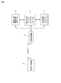
- FIG. 7 is a block diagram showing a functional configuration of the body temperature measuring device 2.
- FIG. 8 is a block diagram showing an overall configuration of a hospital system to which the body temperature measuring device 2 is applied. 7 and 8, the same reference numerals are given to the same or equivalent components as in the first embodiment.
- the body temperature measuring device 2 is different from the body temperature measuring device 1 according to the first embodiment described above in that a temperature information processing unit 50B is provided instead of the temperature information processing unit 50. Further, the temperature information processing unit 50B is different from the body temperature measurement device 1 according to the first embodiment described above in that a body temperature acquisition unit 513B is provided instead of the body temperature acquisition unit 513.
- a body temperature acquisition unit 513B is provided instead of the body temperature acquisition unit 513.
- the body temperature acquisition unit 513B first obtains a body temperature data candidate (or correction value) acquired based on the detected temperature data, and performs statistical processing (for example, k-average method or Ward method) on the body temperature data candidate. And clustering the body temperature data candidates.
- statistical processing for example, k-average method or Ward method
- body temperature data candidates are clustered (stratified) into three layers.
- FIG. 10 shows an example of body temperature data candidates (heat flow compensation calculation results) before performing statistical processing (clustering).
- FIG. 11 shows an example of body temperature data candidates (stratified determination results of heat flow compensation calculation) after performing statistical processing (clustering). 10 and 11, the horizontal axis represents time, and the vertical axis represents temperature or correction value (° C.).
- the body temperature acquisition unit 513B includes a cluster that does not include body temperature data candidates obtained from the temperature data detected when the temperature detection unit 11 is determined to be in a thermally non-equilibrium state (that is, the temperature detection unit).
- Body temperature data is acquired from body temperature data candidates belonging to a cluster of only body temperature data candidates obtained from temperature data detected when 11 is in a thermal equilibrium state.
- the determination method whether the temperature detection part 11 is in a thermal non-equilibrium state detailed description is abbreviate
- FIG. 12 shows an example of body temperature data (compensation calculation result and body temperature calculation value) after removing the cluster (data) to be removed after clustering (stratification determination).
- the horizontal axis represents time
- the vertical axis represents temperature (° C.).
- FIG. 9 is a flowchart showing a processing procedure of deep body temperature measurement processing and body temperature abnormality detection processing by the body temperature measuring device 2.
- the process shown in FIG. 9 is repeatedly executed mainly at a predetermined timing by the temperature information processing unit 50B.
- step S200 temperature data detected by each of the temperature sensors 111 to 114 is read.
- step S202 heat flow compensation calculation is performed on the read temperature data using the heat flow compensation calculation formulas (9) and (10), and body temperature data candidates are calculated (see FIG. 10). Since the method for calculating the body temperature data candidate is as described above, detailed description thereof is omitted here.
- step S204 clustering (stratification) is performed using the k-average method on the body temperature data candidates measured (acquired) continuously for a certain time (see FIG. 11). Since details of clustering are as described above, detailed description is omitted here.
- step S206 a determination is made as to whether or not each cluster (layer) is a valid cluster using the above-described equilibrium state discriminant (1). That is, it is determined whether or not the cluster does not include the body temperature data candidate acquired from the temperature data detected when the thermal equilibrium state is not established. If it is determined that the cluster is valid, the process proceeds to step S208. On the other hand, when it is determined that the cluster is not valid, the process proceeds to step S210.
- step S208 body temperature data candidates included in a cluster determined to be valid are acquired and output as normal body temperature data (see FIG. 12). Thereafter, the process proceeds to step S212.
- step S210 clusters determined to be invalid (body temperature data candidates included in the clusters) are removed (discarded). Thereafter, the process is temporarily exited.
- step S212 a determination is made as to whether or not the deviation between the acquired body temperature data and the average value of the body temperature data measured at the same time until the previous day is within a predetermined 24-hour fluctuation value. Done. If the deviation is within the variation value, the process proceeds to step S214. On the other hand, when the deviation is outside the fluctuation value, the process proceeds to step S216.
- step S214 after the body temperature data is displayed in a normal color (for example, blue), the process is temporarily exited.
- a warning color for example, red
- body temperature data candidates are obtained based on the detected temperature data, statistical processing is performed on the body temperature data candidates, and the body temperature data candidates are clustered.
- body temperature data is acquired from the body temperature data candidate which belongs to the cluster which does not contain the body temperature data candidate calculated
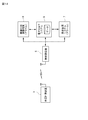
- FIG. 13 is a block diagram showing a functional configuration of the body temperature measuring device 3.
- FIG. 14 is a block diagram showing an overall configuration of a hospital system to which the body temperature measuring device 3 is applied. 13 and 14, the same or equivalent components as those in the first embodiment are denoted by the same reference numerals.
- the body temperature measuring device 3 includes a photoelectric pulse wave sensor 118 that detects a photoelectric pulse wave signal (pulse rate), a piezoelectric sensor 119 that detects a respiratory rate, and an electrocardiogram signal (heart rate). It differs from the body temperature measuring device 1 which concerns on 1st Embodiment mentioned above by the point provided with the electrocardiogram electrode 120 which detects this, and the blood pressure sensor 121 which detects blood pressure.
- the photoelectric pulse wave sensor 118, the piezoelectric sensor 119, the electrocardiographic electrode 120, and the blood pressure sensor 121 correspond to the biological information measuring means described in the claims.
- the body temperature measuring device 3 is different from the body temperature measuring device 1 according to the first embodiment described above in that a temperature information processing unit 50C is provided instead of the temperature information processing unit 50.
- the temperature information processing unit 50C is different from the body temperature measurement device 1 described above in that it includes a heat generation determination unit 516C instead of the heat generation determination unit 516, and includes a notification unit 54C instead of the notification unit 54.
- the other structure is the same as that of the body temperature measuring apparatus 1 mentioned above, it is abbreviate
- the fever determination unit 516C determines whether the body temperature data and biological information (for example, heart rate and respiratory rate) satisfy a predetermined disease management condition in addition to determination of fever (whether the body temperature is within the normal heat range). Determine whether or not.
- the notification unit 54C notifies the user and / or the manager (doctor or nurse) of the body temperature data and the biological information. Informs that the prescribed disease management conditions are satisfied. Specific examples are listed below.
- Suspected sepsis (systemic inflammation reaction group) Suspected sepsis (systemic inflammation reaction group) if any of the following conditions (1), (2), and (3) is satisfied: As a result, a warning display or a warning sound (alarm) is output from the notification unit 54C.
- a warning display or a warning sound is output from the notification unit 54C.
- Suspected surgical site (deep incision) wound infection Reported as suspected surgical site (deep incision) wound infection when the patient falls within 30 days after surgery and the body temperature is> 38 ° C
- a warning display and a warning sound (alarm) are output from the unit 54C.
- body temperature data in addition to body temperature data, other biological information (for example, heart rate, pulse rate, respiratory rate, blood pressure, etc.) is simultaneously measured, and the body temperature data and biological information satisfy predetermined disease management conditions.
- the user and / or manager such as a doctor or nurse
- the body temperature data and the biological information satisfy the predetermined disease management conditions. Therefore, for example, by combining body temperature (fever) and other biological information (for example, heart rate, pulse rate, respiratory rate, blood pressure, etc.), it is possible to detect and notify that there is a specific disease risk described above. It becomes possible.
- the present invention is not limited to the above-described embodiments, and various modifications can be made.
- the present invention is applied to an in-hospital system has been described as an example.
- the present invention may be used alone, and instead of the in-hospital system, for example, an elderly facility It can also be applied to internal systems.
- the body temperature data candidates are calculated from the temperature data, and then the body temperature data candidates calculated from the temperature data detected when the temperature detection unit 11 is in the non-equilibrium state are removed, thereby normalizing
- body temperature data is obtained using temperature data after removing temperature data (noise) detected when the temperature detector 11 is in a non-equilibrium state. It is good also as a structure which acquires.
- the temperature detection part 11 had two sets of sensing parts 11a and 11b, when the thermal resistance RB of a human body can be acquired, the temperature detection part 11 has a set of sensing parts. It only has to have.
- Temperature detector 110 Flexible substrate 111 First temperature sensor 112 Second temperature sensor 113 Third temperature sensor 114 Fourth temperature sensor 115, 116 Thermal resistor 117 Thermal insulation member 118 Photoelectric pulse wave sensor 119 Piezoelectric sensor 120 ECG electrode 121 Blood pressure sensor 50, 50B, 50C Temperature information processing unit 51 MCU 511 Equilibrium state determination unit 513, 513B Body temperature acquisition unit 514 Personal characteristic information acquisition unit 515 Normal heat range setting unit 516, 516C Heat generation determination unit 517 Storage unit (memory) 52 Wireless communication module 53 Battery 54, 54C Notification unit
Landscapes
- Health & Medical Sciences (AREA)
- Life Sciences & Earth Sciences (AREA)
- Engineering & Computer Science (AREA)
- Physics & Mathematics (AREA)
- Medical Informatics (AREA)
- Public Health (AREA)
- Biomedical Technology (AREA)
- General Health & Medical Sciences (AREA)
- Pathology (AREA)
- Veterinary Medicine (AREA)
- Heart & Thoracic Surgery (AREA)
- Molecular Biology (AREA)
- Surgery (AREA)
- Animal Behavior & Ethology (AREA)
- Biophysics (AREA)
- Physiology (AREA)
- General Physics & Mathematics (AREA)
- Artificial Intelligence (AREA)
- Epidemiology (AREA)
- Primary Health Care (AREA)
- Signal Processing (AREA)
- Psychiatry (AREA)
- Computer Vision & Pattern Recognition (AREA)
- Mathematical Physics (AREA)
- Fuzzy Systems (AREA)
- Evolutionary Computation (AREA)
- Databases & Information Systems (AREA)
- Data Mining & Analysis (AREA)
- Computer Networks & Wireless Communication (AREA)
- Business, Economics & Management (AREA)
- General Business, Economics & Management (AREA)
- Measuring And Recording Apparatus For Diagnosis (AREA)
- Measuring Temperature Or Quantity Of Heat (AREA)
Abstract
体温計測装置(1)は、熱抵抗体(115)、並びに該熱抵抗体(115)を挟むように配置され、連続的に温度データを検出する一対の温度センサ(111,112)、及び、熱抵抗体(116)、並びに該熱抵抗体(116)を挟むように配置され、連続的に温度データを検出する一対の温度センサ(113,114)を有する温度検出部(11)と、温度検出部(11)が熱的に平衡状態であるか否かを判定する平衡状態判定部(511)と、温度検出部(11)が熱的平衡状態にあると判定されたときに検出された温度データ、及び熱抵抗体(115,116)の熱抵抗値に基づいて体温データを取得する体温取得部(513)とを備える。
Description
本発明は、体温計測装置に関し、特に、連続的に体温(深部体温)を計測する体温計測装置に関する。
従来から、連続的に体表温度を検出して体温(深部体温)を計測する技術が提案されている。例えば特許文献1には、時系列の体表温度データ(例えば、就寝中に測定した被測定者の体表温度データ)に基づいて口中温度等の体温を推定する装着式温度測定装置が開示されている。
より具体的には、この装着式温度測定装置は、体表の温度を検出する体表温度検出部、外気に影響を受けた体表の温度を補助的に検出する補助体表温度検出部、及び外気温度を検出する外気温度検出部を有しており、予め測定した体表温度データ群と体温とを用いてPLS回帰分析によって逆演算モデルを構築する。そして、この装着式温度測定装置は、逆演算モデルを用いて、各温度検出部により検出された温度検出データを時系列に並べた温度データ群から体温を推定する。
この装着式温度測定装置によれば、逆演算モデルを用いて体表温度データ群から体温を推定するため、例えば毎日の体温に基づいて被測定者の健康管理を行う場合でも容易に利用することができる。さらに、逆演算モデルを用いて、数時間に亘って計測した体表温度検出データから体温を推定するため、口中温度等の体温を直接計測した場合に比べて、計測の揺らぎの影響を抑制することができる。
ところで、体表面温度は外気温などの外乱により大きく変動する。すなわち、例えば、暖かい室内から寒い屋外に移動した際など、急激な温度変化が生じた場合に、体表面温度は大きく変動する。
これに対し、上述した装着式温度測定装置では、PLS回帰分析により構築された逆演算モデルを用いて体温を推定しているが、原理的に外気温などの外乱の影響を正しく補正(補償)する機能を有していないため、外乱の影響を適切に排除することができないおそれがある。また、上述した装着式温度測定装置では、逆演算モデルを用いて、数時間に亘って計測した体表温度検出データから体温を推定するため、比較的短い時間(スパン)での発熱などを把握することが困難であったり、把握が遅れたりするおそれがある。
本発明は、上記問題点を解消する為になされたものであり、外乱の影響を適切に排除することができ、かつ、より短い時間(スパン)で発熱を把握することが可能な体温計測装置を提供することを目的とする。
本発明に係る体温計測装置は、熱抵抗体、及び該熱抵抗体を挟むように配置され、連続的に温度データを検出する複数の温度センサを有する温度検出部と、温度検出部が熱的に平衡状態であるか否かを判定する平衡状態判定手段と、平衡状態判定手段により温度検出部が熱的平衡状態にあると判定されたときに検出された温度データ、及び熱抵抗体の熱抵抗値に基づいて体温データを取得する体温取得手段とを備えることを特徴とする。
本発明に係る体温計測装置によれば、温度検出部(複数の温度センサ)が熱的に平衡状態(熱流量の変動がない状態)であるか否かが判定され、温度検出部が熱的平衡状態にあると判定されたときに検出された温度データ、及び熱抵抗体の熱抵抗値に基づいて体温データが取得される。そのため、例えば、部屋の出入りなどに伴う雰囲気温度の急変など(外乱)により温度検出部が一時的に非平衡状態となったとしても、非平衡状態となったこと(非平衡状態であること)を把握して、不正確な温度データ(ノイズ)を取り除くことができる。また、このようにノイズ(非平衡状態での温度データ)を除去できるため、例えば時定数の大きなローパスフィルタなどを入れてデータをなまらせる必要がない。その結果、外乱の影響を適切に排除することができ、かつ、より短い時間(スパン)で発熱を把握することが可能となる。
本発明によれば、外乱の影響を適切に排除することができ、かつ、より短い時間(スパン)で発熱を把握することが可能となる。
以下、図面を参照して本発明の好適な実施形態について詳細に説明する。なお、図中、同一又は相当部分には同一符号を用いることとする。また、各図において、同一要素には同一符号を付して重複する説明を省略する。
(第1実施形態)
まず、図1~図3を併せて用いて、第1実施形態に係る体温計測装置1の構成について説明する。なお、ここでは、体温計測装置1を、例えば、病院内システム(電子カルテシステム6及び感染管理システム7)に適用した場合を例にして説明する。図1は、体温計測装置1の機能構成を示すブロック図である。図2は、体温計測装置1が適用された病院内システムの全体構成を示すブロック図である。図3は、体温計測装置1を構成する温度検出部11の構成を示す図である。
まず、図1~図3を併せて用いて、第1実施形態に係る体温計測装置1の構成について説明する。なお、ここでは、体温計測装置1を、例えば、病院内システム(電子カルテシステム6及び感染管理システム7)に適用した場合を例にして説明する。図1は、体温計測装置1の機能構成を示すブロック図である。図2は、体温計測装置1が適用された病院内システムの全体構成を示すブロック図である。図3は、体温計測装置1を構成する温度検出部11の構成を示す図である。
体温計測装置1は、主として、体表面に貼り付けられて温度を検出する温度検出部(非加熱式の深部体温計)11、及び温度検出部11により検出された温度に基づいて深部体温を取得する温度情報処理ユニット50を備えて構成されている。ここで、温度検出部11は、主として、フレキシブル基板110と、2組のセンシング部11a,11bとを有して構成されている。また、温度情報処理ユニット50は、主として、MCU51、無線通信モジュール52、バッテリ53、及び報知部54を有して構成されている。以下、各構成要素について詳細に説明する。
温度検出部11は、使用者の体表面に貼り付けられて該使用者の体表面等の温度を検出する。上述したように、温度検出部11は、2組のセンシング部11a,11bを有している。一方のセンシング部11aは、所定の熱抵抗値を有する熱抵抗体115と、例えば可撓性を有するフレキシブル基板(フィルム基板)110に実装され、熱抵抗体115を、その厚さ方向から挟むように配置された一対の温度センサ、すなわち、第1温度センサ111及び第2温度センサ112とを有して構成されている。なお、第1温度センサ111及び第2温度センサ112それぞれは、例えば、熱抵抗体115の中に埋め込まれていてもよい。
他方のセンシング部11bは、熱抵抗体115と異なる熱抵抗値を有する熱抵抗体116と、フレキシブル基板(フィルム基板)110に実装され、熱抵抗体116を、その厚さ方向から挟むように配置された一対の温度センサ、すなわち、第3温度センサ113及び第4温度センサ114とを有して構成されている。なお、第3温度センサ113及び第4温度センサ114それぞれは、例えば、熱抵抗体116の中に埋め込まれていてもよい。また、2組のセンシング部11a,11bそれぞれは、第2温度センサ112を覆うように配置されたシート状の断熱部材117、及び、第4温度センサ114を覆うように配置されたシート状の断熱部材117をさらに有している。
熱抵抗体115,116は、例えば、所定の厚みを有する、矩形の薄いシート状に形成されている。なお、熱抵抗体115,116の形状は、矩形に限られることなく、例えば、円形などであってもよい。熱抵抗体115,116は、断熱性を有する素材、例えば、ポリエチレン発泡体やウレタン発泡体などによって形成される。また、熱抵抗体115,116は、体表面の形状や動きに沿うように、柔軟性を有している。ここで、断熱性及び柔軟性を考慮し、熱抵抗体115,116の厚みは、例えば、0.1mm~数mm程度であることが好ましい。特に、熱抵抗体115の熱抵抗値は、熱抵抗体116の熱抵抗値と異なるように設定されている。なお、熱抵抗体115,116の熱抵抗値は、例えば、熱抵抗体の厚み等を変更することにより調節することができる。
異なる熱抵抗値を有する熱抵抗体115,116を用いた2組のセンシング部11a,11bを有しているため、すなわち、熱抵抗値が異なる2系統の熱流系が形成されるため、人体の熱抵抗RBの項をキャンセルすることができ、人体の熱抵抗RBが未知であっても体温(深部体温)を求めることができる。よって、人体の熱抵抗RBを仮定するとなく深部体温を取得することができるため、各使用者の熱抵抗RBが異なる場合であっても、深部体温をより精度よく取得することができる。なお、人体の熱抵抗RBのキャンセル方法については後述する。
温度センサ111~114としては、例えば、温度によって抵抗値が変化するサーミスタや測温抵抗体などが好適に用いられる。なお、温度センサ111~114は、応答性を高める観点から、できるだけ熱容量が小さいことが好ましい。よって、温度センサ111~114としては例えばチップサーミスタが好適に用いられる。4つの温度センサ111~114それぞれは、プリント配線を介して、温度情報処理ユニット50(MCU51)と電気的に接続されており、温度に応じた電気信号(電圧値)が温度情報処理ユニット50(MCU51)で読み込まれる。
温度情報処理ユニット50は、主として、MCU(Micro Control Unit)51、無線通信モジュール52、バッテリ53、及び報知部54等を有して構成されている。
上述したように、4つの温度センサ111~114は、温度情報処理ユニット50(MCU51)に接続されており、各温度センサ111~114から出力された検出信号(温度データ)は温度情報処理ユニット50(MCU51)に入力される。
温度情報処理ユニット50は、一方のセンシング部11aを構成する熱抵抗体115の熱抵抗値、第1温度センサ111の検出温度、並びに第2温度センサ112の検出温度、及び、他方のセンシング部11bを構成する熱抵抗体116の熱抵抗値、第3温度センサ113の検出温度、並びに第4の温度センサ114の検出温度に基づいて、体温(深部体温)を求める。なお、詳細については後述する。また、体温(深部体温)を求める際に、熱抵抗体115及び熱抵抗体116の熱抵抗値に代えて、例えば、熱抵抗体115及び熱抵抗体116の熱容量や、比熱、密度、形状などといった物性値を用いてもよい。
特に、温度情報処理ユニット50は、外乱の影響を適切に排除することができ、かつ、より短い時間(スパン)で発熱を把握する機能を有している。そのため、温度情報処理ユニット50は、平衡状態判定部511、体温取得部513、個人特性情報取得部514、平熱範囲設定部515、発熱判別部516、及び記憶部(メモリ)517を機能的に備えている。温度情報処理ユニット50では、ROM等に記憶されているプログラムがMCU51によって実行されることにより、平衡状態判定部511、体温取得部513、個人特性情報取得部514、平熱範囲設定部515、発熱判別部516の機能が実現される。
平衡状態判定部511は、平衡状態判別式を用いて温度検出部11(温度センサ111~114)が熱的に平衡状態(熱流量の変動がない状態)であるか否かを判定する。すなわち、平衡状態判定部511は、請求の範囲に記載の平衡状態判定手段として機能する。より具体的には、平衡状態判定部511は、次の平衡状態判別式(1)を用いて、温度検出部11が熱的に平衡状態であるか否かを判定する。すなわち、第1温度センサ111により検出された温度データをT1、第2温度センサ112により検出された温度データをT2、第3温度センサ113により検出された温度データをT3、第4温度センサ114により検出された温度データをT4とした場合、平衡状態判定部511は、平衡状態判別式(1)が満足された場合には、温度検出部11(温度センサ111~114)が熱的に平衡状態であると判定する。一方、平衡状態判定部511は、平衡状態判別式(1)が満足されない場合には、温度検出部11(温度センサ111~114)が熱的に平衡状態ではない(非平衡状態である)と判定する。
T3-T4>T1-T2, T3>T1 ・・・(1)
T3-T4>T1-T2, T3>T1 ・・・(1)
なお、病院内の気温Taを例えば電子カルテシステム6(又は感染管理システム7)から取得できる場合には、次の平衡状態判別式(2)(3)(4)をさらに考慮して、温度検出部11(4つの温度センサ111~114)が熱的に平衡状態であるか否かを判定してもよい。その場合、上記平衡状態判別式(1)に加えて、平衡状態判別式(2)(3)(4)が全て満足された場合には、温度検出部11(温度センサ111~114)が熱的に平衡状態であると判定される。一方、いずれかの平衡状態判別式(1)~(4)又はすべての平衡状態判別式(1)~(4)が満足されない場合には、温度検出部11(温度センサ111~114)が熱的に平衡状態ではない(非平衡状態である)と判定される。
dTa>dT4 ・・・(2)
K(T1-T2)-(T3-T4)>0(Ta>Tbのとき) ・・・(3)
K(T1-T2)-(T3-T4)≦0(Ta≦Tbのとき) ・・・(4)
ただし、定数Kは2つの熱流における熱抵抗の比である。
dTa>dT4 ・・・(2)
K(T1-T2)-(T3-T4)>0(Ta>Tbのとき) ・・・(3)
K(T1-T2)-(T3-T4)≦0(Ta≦Tbのとき) ・・・(4)
ただし、定数Kは2つの熱流における熱抵抗の比である。
さらに、上記平衡状態判別式(1)~(4)に代えて(又は加えて)、次の平衡状態判別式(5)~(8)を用いて温度検出部11(温度センサ111~114)が熱的に平衡状態であるか否かを判定してもよい。その場合、次の平衡状態判別式(5)~(8)のうち少なくともいずれか一つの平衡状態判別式が満足された場合には、温度検出部11(温度センサ111~114)が熱的に平衡状態であると判定される。一方、次の平衡状態判別式(5)~(8)がすべて満足されない場合には、温度検出部11(温度センサ111~114)が熱的に平衡状態ではない(非平衡状態である)と判定される。
ΔT3<a ・・・(5)
(ただし、aは、例えば、0.2(℃/min)などの所定値である)
ΔT1<a ・・・(6)
(ただし、aは、例えば、0.2(℃/min)などの所定値である)
ΔT3<ΔT4 ・・・(7)
ΔT1<ΔT2 ・・・(8)
平衡状態判定部511による判定結果(温度検出部11が熱的に平衡状態であるか否かの情報)は、体温取得部513に出力される。
ΔT3<a ・・・(5)
(ただし、aは、例えば、0.2(℃/min)などの所定値である)
ΔT1<a ・・・(6)
(ただし、aは、例えば、0.2(℃/min)などの所定値である)
ΔT3<ΔT4 ・・・(7)
ΔT1<ΔT2 ・・・(8)
平衡状態判定部511による判定結果(温度検出部11が熱的に平衡状態であるか否かの情報)は、体温取得部513に出力される。
体温取得部513は、予め記憶されている熱抵抗体115の熱抵抗値RpA、第1温度センサ111の検出温度T1、並びに第2温度センサ112の検出温度T2、及び、予め記憶されている熱抵抗体116の熱抵抗値RpB、第3温度センサ113の検出温度T3、並びに第4温度センサ114の検出温度T4に基づいて、体温データ(深部体温)を求める。特に、体温取得部513は、温度検出部11が熱的平衡状態にあると判定されたときに検出された温度データに基づいて体温データを取得する。すなわち、体温取得部513は、請求の範囲に記載の体温取得手段として機能する。
より具体的には、体温取得部513は、まず、検出された温度データに対して温度補償計算を行い、体温データ候補(又は補正値)を算出する。次に、体温取得部513は、熱的平衡状態の判定結果に基づいて、非平衡状態時に検出された温度データから求められた体温データ候補(又は補正値)を取り除き、正規の体温データを取得する。以下、より詳細に説明する。
体温取得部513は、次式(9)(10)を用いて、熱抵抗体(熱抵抗)が異なる2つの系の熱流比較により、未知の熱抵抗RBを消去し、当該未知の熱抵抗RBを持つ使用者(人体)の体温データ候補Tbを算出(推定)する。
IpA=(T1-T2)/RpA=(Tb-T1)/RB ・・・(9)
IpB=(T3-T4)/RpB=(Tb-T3)/RB ・・・(10)
ただし、RpA,RpBは、熱抵抗体115,116の熱抵抗(既知)である。
IpA=(T1-T2)/RpA=(Tb-T1)/RB ・・・(9)
IpB=(T3-T4)/RpB=(Tb-T3)/RB ・・・(10)
ただし、RpA,RpBは、熱抵抗体115,116の熱抵抗(既知)である。
なお、使用者(人体)の熱抵抗RBが既知の場合には、一方のセンシング部11a(又は11b)により体温データ候補を算出(推定)可能である。より詳細には、人体の体温データ候補をTb、第1温度センサ111の検出温度をT1、第2温度センサ112の検出温度をT2とし、人体深部から体表面までの等価的な熱抵抗をRB、熱抵抗体115の厚さ方向の等価的な熱抵抗をRpAとした場合、熱平衡状態に達した状態での体温データ候補Tbは、次式(11)のように表現することができる。
Tb=T2+{RpA/(RB+RpA)}(T1-T2) ・・・(11)
Tb=T2+{RpA/(RB+RpA)}(T1-T2) ・・・(11)
よって、人体の熱抵抗RBが既知の場合、又は人体の熱抵抗RBとして例えば一般的な(標準的な)熱抵抗値を設定することにより、第1温度センサ111で検出された温度T1、及び第2温度センサ112で検出された温度T2から深部体温Tbを求めることができる。
次に、体温取得部513は、上述した熱的平衡状態判定結果に基づき、熱的に非平衡状態にあるとき検出された温度データから求められた体温データ候補を取り除き、熱的に平衡状態にあるとき検出された温度データから求められた体温データ候補を正規の体温データとして取得する。ここで、平衡状態判定を行う前(すなわち、非平衡状態時に検出された温度データから求められた体温データ候補を取り除く前)の体温データ候補(熱流補償計算結果)の一例を図5に示す。また、平衡状態判定を行った後(すなわち、非平衡状態時に検出された温度データから求められた体温データ候補を取り除いた後)の体温データ(熱流補償計算結果)の一例を図6に示す。なお、図5,6の横軸は時刻であり、縦軸は温度(℃)である。図5及び図6に示されるように、温度検出部11が非平衡状態にあるときに検出された温度データ(不正確な温度データ)から求められた体温データ候補(ノイズ)が取り除かれる。
体温取得部513により取得された体温データ(深部体温Tb)は、発熱判別部516、無線通信モジュール52、及び記憶部517に出力される。
個人特定情報取得部514は、使用者の個人特性情報(例えば、年齢、性別、身長、体重など)を取得する。すなわち、個人特定情報取得部514は、請求の範囲に記載の取得手段として機能する。使用者の個人特性情報は、例えば、無線通信(無線通信機5及び無線通信モジュール52)を介して、電子カルテシステム6などから取得することができる。また、例えばタッチパネル等の入力I/Fを備えておき、該入力I/Fから情報を入力する構成としてもよい。個人特定情報取得部514により取得された使用者の個人特性情報は、記憶部517に記憶され、必要に応じて平熱範囲設定部515に出力される。
平熱範囲設定部515は、使用者の平熱範囲(平熱の期待値範囲)を設定する。すなわち、平熱範囲設定部515は、請求の範囲に記載の設定手段として機能する。より詳細には、平熱範囲設定部515は、一日の時刻と対応付けて(時刻ごとに)使用者の平熱範囲(平熱の期待値範囲)を設定する。また、平熱範囲設定部515は、使用者の個人特性情報に基づいて、使用者と同じカテゴリに属する統計データから、該使用者の平熱範囲(平熱の期待値範囲)を設定する。より具体的には、平熱範囲設定部515は、使用者と同じカテゴリ(例えば同じ年齢や性別)に属する人の統計データ(例えば、平均値Aveと標準偏差σ)から、例えば「Ave±3σ」を平熱範囲(平熱の期待値範囲)として設定する。
ここで、上記統計データ(平均値と標準偏差)は、例えば、無線通信(無線通信機5及び無線通信モジュール52)を介して、予め、電子カルテシステム6などから取得し、記憶部517に記憶しておく。なお、例えば、平熱範囲設定部515の機能を電子カルテシステム6側に持たせ、電子カルテシステム6側で使用者の平熱範囲(平熱の期待値範囲)を設定する構成としてもよい。
さらに、平熱範囲設定部515は、過去に取得され、記憶部517に記憶されている使用者の体温データを学習し、学習した学習値を考慮して使用者の平熱範囲を設定(又は補正)することが好ましい。ところで、平熱は、通常、日内で1℃以上変動し、また、年齢や性別などの個人特性によっても異なり、さらに個人差もある。これに対し、本実施形態によれば、日内の変動、及び年齢や性別などの個人特性を考慮して平熱範囲(平熱の期待値範囲)が設定されるとともに、学習値(学習結果)を用いて個人差が補正される。なお、平熱範囲設定部515により設定された使用者の平熱範囲(平熱の期待値範囲)は、発熱判別部516に出力される。
発熱判別部516は、体温が平熱範囲内か否か(体温異常か否か)を判別(検知)する。すなわち、発熱判別部516は、請求の範囲に記載の判別手段として機能する。発熱判別部516による判別結果(使用者の体温が平熱範囲内であるか否かの情報)は、報知部54に出力される。
報知部54は、例えば、LCDディスプレイやブザー(又はスピーカ)を有しており、体温データが平熱範囲外となった場合に、使用者及び/又は管理者(本実施形態では医師や看護師など)に対して、体温データが平熱範囲外となった旨を報知する。報知部54は、体温が平熱範囲(Ave±3σ)から外れた場合に、例えば、警告表示や警告音(アラームやビープ音)を出力する。すなわち、報知部54は、請求の範囲に記載の報知手段として機能する。なお、報知部54は、無線通信(無線通信モジュール52及び無線通信機5)を介して、電子カルテシステム6に報知情報(警告情報)を送信することが好ましい。報知情報(警告情報)を受信した場合、電子カルテシステム6は、電気的に接続されている(看護師用)携帯端末8や(医師用)感染管理システム7に対して、警告表示や警告音(アラームやビープ音)の出力要求を行う。これにより、看護師や医師に対して、使用者(患者)の体温異常を認識させることができる。なお、報知部54は、無線通信(無線通信モジュール52及び無線通信機5)を介して、上記報知情報(警告情報)を、(看護師用)携帯端末8や(医師用)感染管理システム7に直接送信し、警告表示や警告音(アラームやビープ音)の出力要求を行うことも可能である。
また、報知部54は、体温データが所定の疾病管理条件を満足した場合に、使用者及び/又は管理者(本実施形態では医師や看護師など)に対して、体温データが所定の疾病管理条件を満足した旨を報知する。例えば、報知部54は、一定以上の体温や一定以上の体温上昇を検知した場合に、例えば、警告表示や警告音(アラームやビープ音)を出力する。また、この場合も、上述したように、無線通信(無線通信モジュール52及び無線通信機5)を介して、電子カルテシステム6に報知情報(警告情報)を送信することが好ましい。
さらに、報知部54は、所定時間以上、体温データを取得できない場合に計測異常である旨を報知する。例えば、報知部54は、30分以上、体温データを取得できない場合に、計測異常としてアラームを出力する。また、この場合も、上述したように、無線通信(無線通信モジュール52及び無線通信機5)を介して、電子カルテシステム6に報知情報(警告情報)を送信することが好ましい。
無線通信モジュール52は、取得された体温データや上述した報知情報(警告情報)を外部の無線通信機5(電子カルテシステム6)等に送信する。また、無線通信モジュール52は、上述した使用者の個人特性情報、及び平熱範囲を設定するための統計データ(平均値と標準偏差)などを無線通信機5(電子カルテシステム6)から受信する。無線通信モジュール52は、例えば、BT(Bluetooth(登録商標))などを用いて上記情報を送受信する。
また、温度情報処理ユニット50には、その内部に、薄型のバッテリ53が収納さえている。バッテリ53は、MCU51や無線通信モジュール52などに電力を供給する。
次に、図4を参照しつつ、体温計測装置1の動作について説明する。図4は、体温計測装置1による深部体温計測処理及び体温異常検知処理の処理手順を示すフローチャートである。図4に示される処理は、主として温度情報処理ユニット50によって、所定のタイミングで繰り返して実行される。
まず、ステップS100では、各温度センサ111~114により検出された温度データが読み込まれる。
次に、ステップS102では、読み込まれた温度データに対して、上記熱流補償計算式(9)(10)を用いて熱流補償計算が実行され、体温データ候補が算出される(図5参照)。ねお、熱流補償計算については、上述したとおりであるので、ここでは詳細な説明を省略する。
続いて、ステップS104では、上述した平衡状態判別式(1)を用いて、温度検出部11(温度センサ111~114)が熱的に平衡状態(熱流量が変動しない状態)であるか否かについての判断が行われる。ここで、熱的平衡状態であると判断される場合には、ステップS106に処理が移行する。一方、熱的平衡状態でないと判断されるときには、ステップS108に処理が移行する。
ステップS106では、ステップS102で算出された体温データ候補が正規の体温データとして取得され、出力される(図6参照)。その後、ステップS110に処理が移行する。一方、ステップS108では、ステップS102で算出された体温データ候補が除去(廃棄)される。その後、本処理から一旦抜ける。
ステップS110では、ステップS106で取得された体温データが表示される。
次に、ステップS112では、例えば、無線通信を介して、病院の電子カルテシステム6から、使用者の個人特性情報(例えば、年齢、性別、身長、体重など)が取得される。
続いて、ステップS114では、個人特性と対応付けて予め記憶されている平熱範囲(統計データ)から、使用者の個人特性とカテゴリ(例えば同じ年齢や性別など)が一致する個人特性と対応付けて記憶されている時刻毎の平熱範囲(平熱の期待値範囲)が取得される。
続くステップS116では、体温が、同時刻の平熱範囲内であるか否かについての判断が行われる。ここで、体温が平熱範囲内にある場合には、(例えば警告表示や警告音が出力されることなく)本処理から一旦抜ける。一方、体温が平熱範囲外にあるときには、ステップS118に処理が移行する。
ステップS118では、体温データが平熱範囲外にあることが通知される。すなわち、例えば、体温データが平熱範囲外にあることを示す警告表示や警告音が出力される。
以上、詳細に説明したように、本実施形態によれば、平衡状態判別式(1)を用いて温度検出部11(4つの温度センサ111~114)が熱的に平衡状態であるか否かが判定され、温度検出部11が熱的平衡状態にあると判定されたときに検出された温度データに基づいて体温データが取得される。そのため、例えば、部屋の出入りなどに伴う雰囲気温度の急変など(外乱)により温度検出部11が一時的に非平衡状態となったとしても、非平衡状態となったこと(非平衡状態であること)を把握して、不正確な体温データ候補/温度データ(ノイズ)を取り除くことができる。また、このようにノイズ(非平衡状態での体温データ候補/温度データ)を除去できるため、例えば時定数の大きなローパスフィルタなどを入れてデータをなまらせる必要がない。その結果、外乱の影響を適切に排除することができ、かつ、より短い時間(スパン)で発熱を把握することが可能となる。
本実施形態によれば、使用者の個人特性情報(例えば、年齢、性別、身長、体重など)が取得され、取得された使用者の個人特性情報、及び、個人特性と対応付けて記憶されている平熱範囲(平熱の期待値範囲)に基づいて、当該使用者の平熱範囲(平熱の期待値範囲)が設定される。すなわち、使用者の個人特性と合致する統計データから平熱範囲が個別に設定される。そして、体温データが、設定された平熱範囲内か否かが判別される。よって、例えば、平熱範囲から外れた発熱(体温異常)などを早期にかつ的確に検知することが可能となる。
本実施形態によれば、一日の時刻と対応付けて時刻ごとに使用者の平熱範囲(平熱の期待値範囲)が設定される。そのため、例えば、体温の日内変動を考慮することができ、平熱範囲から外れた発熱をより的確に検知することが可能となる。その結果、例えば、昼夜を問わず、病院内において患者の発熱を正確にかつ早期に検知することができる。
本実施形態によれば、過去に取得された使用者の体温データが学習され、学習された学習値を考慮して使用者の平熱範囲(平熱の期待値範囲)が設定(又は補正)される。そのため、学習効果により、使用者ごとの平熱範囲の確からしさをより高めることが可能となる。
本実施形態によれば、体温データが平熱範囲外となった場合に、使用者及び/又は管理者(医師や看護師)に対して、体温データが平熱範囲外となった旨が報知される。そのため、体温データが平熱範囲外となったことが検知された際、その旨(発熱している旨)を使用者及び/又は管理者に認識させることが可能となる。その結果、例えば、昼夜を問わず、病院内において患者の発熱を正確にかつ早期に把握することができ、治療等の対策活動を早期に開始することが可能となる。特に、入院患者などの体温を連続して測定し、発熱アラームを通知したい場合、入院患者の舌下や腋下に体温計をその都度挿入するなどの特別な手間を必要とせず、入院患者の体幹部に貼り付けておくだけで長時間連続的に機能させることができる。
本実施形態によれば、体温データが所定の疾病管理条件を満足した場合に、使用者及び/又は管理者(医師や看護師)に対して、体温データが所定の疾病管理条件を満足した旨が報知される。そのため、例えば、一定以上の体温もしくは体温上昇を検知した際などに、その旨を使用者及び/又は管理者に認識させることが可能となる。
本実施形態によれば、所定時間(例えば30分)以上、体温データが取得されない場合に計測異常である旨が報知される(例えば警告表示や警告音(アラーム)が出力される)。そのため、使用者(医師や看護師)等は、計測異常を早期に認識することができる。
(第2実施形態)
次に、図7,8を併せて用いて、第2実施形態に係る体温計測装置2について説明する。ここでは、上述した第1実施形態と同一・同様な構成については説明を簡略化又は省略し、異なる点を主に説明する。図7は、体温計測装置2の機能構成を示すブロック図である。図8は、体温計測装置2が適用された病院内システムの全体構成を示すブロック図である。なお、図7,8において第1実施形態と同一又は同等の構成要素については同一の符号が付されている。
次に、図7,8を併せて用いて、第2実施形態に係る体温計測装置2について説明する。ここでは、上述した第1実施形態と同一・同様な構成については説明を簡略化又は省略し、異なる点を主に説明する。図7は、体温計測装置2の機能構成を示すブロック図である。図8は、体温計測装置2が適用された病院内システムの全体構成を示すブロック図である。なお、図7,8において第1実施形態と同一又は同等の構成要素については同一の符号が付されている。
体温計測装置2は、温度情報処理ユニット50に代えて、温度情報処理ユニット50Bを備えている点で、上述した第1実施形態に係る体温計測装置1と異なっている。また、温度情報処理ユニット50Bは、体温取得部513に代えて体温取得部513Bを備えている点で、上述した第1実施形態に係る体温計測装置1と異なっている。なお、その他の構成は、上述した体温計測装置1と同一又は同様であるので、ここでは詳細な説明を省略する。
体温取得部513Bは、まず、検出された温度データに基づいて取得した体温データ候補(又は補正値)を求め、該体温データ候補に対して統計処理(例えば、k平均法やウォード法など)を施して、該体温データ候補をクラスタ化する。ここで、体温データ候補の求め方については上述した第1実施形態と同一であるので、ここでは詳細な説明を省略する。また、本実施形態では、統計処理にk平均法を用い、体温データ候補を3層にクラスタ化(層別化)した。
ここで、統計処理(クラスタ化)を行う前の体温データ候補(熱流補償計算結果)の一例を図10に示す。また、統計処理(クラスタ化)を行った後の体温データ候補(熱流補償計算の層別判定結果)の一例を図11に示す。なお、図10,11の横軸は時刻であり、縦軸は温度又は補正値(℃)である。
次に、体温取得部513Bは、温度検出部11が熱的に非平衡状態にあると判定されたときに検出された温度データから求められた体温データ候補を含まないクラスタ(すなわち、温度検出部11が熱的に平衡状態にあるときに検出された温度データから求められた体温データ候補のみからなるクラスタ)に属する体温データ候補から体温データを取得する。なお、温度検出部11が熱的に非平衡状態にあるか否かの判定方法については、上述したとおりであるので、ここでは詳細な説明を省略する。
ここで、クラスタ化(層別判定)後、除去対象クラスタ(データ)を除去した後の体温データ(補償計算結果と体温計算値)の一例を図12に示す。なお、図12の横軸は時刻であり、縦軸は温度(℃)である。
次に、図9を参照しつつ、体温計測装置2の動作について説明する。図9は、体温計測装置2による深部体温計測処理及び体温異常検知処理の処理手順を示すフローチャートである。図9に示される処理は、主として温度情報処理ユニット50Bによって、所定のタイミングで繰り返して実行される。
まず、ステップS200では、各温度センサ111~114により検出された温度データが読み込まれる。
次に、ステップS202では、読み込まれた温度データに対して、上記熱流補償計算式(9)(10)を用いて熱流補償計算が実行され、体温データ候補が算出される(図10参照)。なお、体温データ候補の算出方法については上述したとおりであるので、ここでは詳細な説明を省略する。
続いて、ステップS204では、一定時間継続して計測(取得)された体温データ候補に対して、k平均法を用いてクラスタ化(層別化)が行われる(図11参照)。なお、クラスタ化の詳細については上述したとおりであるので、ここでは詳細な説明を省略する。
続いて、ステップS206では、上述した平衡状態判別式(1)を用いて、各クラスタ(層)それぞれが、有効なクラスタであるか否かについての判断が行われる。すなわち、熱的平衡状態にないときに検出された温度データから取得された体温データ候補を含まないクラスタであるか否かについての判断が行われる。ここで、有効なクラスタであると判断される場合には、ステップS208に処理が移行する。一方、有効なクラスタでないと判断されるときには、ステップS210に処理が移行する。
ステップS208では、有効と判断されたクラスタに含まれる体温データ候補が正規の体温データとして取得され、出力される(図12参照)。その後、ステップS212に処理が移行する。一方、ステップS210では、無効と判断されたクラスタ(当該クラスタに含まれる体温データ候補)が除去(廃棄)される。その後、本処理から一旦抜ける。
ステップS212では、取得された体温データと、前日までの同時刻に計測された体温データの平均値との偏差が、予め定められている24時間の変動値内であるか否かについての判断が行われる。ここで、上記偏差が変動値内である場合には、ステップS214に処理が移行する。一方、上記偏差が変動値外であるときには、ステップS216に処理が移行する。
ステップS214では、体温データが平常色(例えば青色等)で表示された後、本処理から一旦抜ける。一方、ステップS216では、体温データが警告色(例えば赤色等)で表示された後、本処理から一旦抜ける。
本実施形態によれば、検出された温度データに基づいて体温データ候補が求められ、該体温データ候補に対して統計処理が施されて、該体温データ候補がクラスタ化される。そして、温度検出部11が熱的に非平衡状態にあると判定されたときに検出された温度データから求められた体温データ候補を含まないクラスタに属する体温データ候補から体温データが取得される。そのため、例えば、部屋の出入りなどに伴う雰囲気温度の急変など(外乱)により温度検出部11が一時的に非平衡状態となったとしても、非平衡状態となったこと(非平衡状態であること)を把握して、非平衡状態のときに検出された不正確な温度データ(ノイズ)から求められた体温データ候補を含むクラスタを取り除くことができる。その結果、外乱の影響をより確実に排除することが可能となる。
(第3実施形態)
次に、図13、図14を併せて用いて、第3実施形態に係る深部体温計3について説明する。ここでは、上述した第1実施形態と同一・同様な構成については説明を簡略化又は省略し、異なる点を主に説明する。図13は、体温計測装置3の機能構成を示すブロック図である。図14は、体温計測装置3が適用された病院内システムの全体構成を示すブロック図である。なお、図13,14において第1実施形態と同一又は同等の構成要素については同一の符号が付されている。
次に、図13、図14を併せて用いて、第3実施形態に係る深部体温計3について説明する。ここでは、上述した第1実施形態と同一・同様な構成については説明を簡略化又は省略し、異なる点を主に説明する。図13は、体温計測装置3の機能構成を示すブロック図である。図14は、体温計測装置3が適用された病院内システムの全体構成を示すブロック図である。なお、図13,14において第1実施形態と同一又は同等の構成要素については同一の符号が付されている。
体温計測装置3は、4つの温度センサ111~114に加えて、光電脈波信号(脈拍数)を検出する光電脈波センサ118、呼吸数を検出する圧電センサ119、心電信号(心拍数)を検出する心電電極120、及び、血圧を検出する血圧センサ121を備えている点で、上述した第1実施形態に係る体温計測装置1と異なっている。なお、光電脈波センサ118、圧電センサ119、心電電極120、血圧センサ121は、請求の範囲に記載の生体情報計測手段に相当する。
また、体温計測装置3は、温度情報処理ユニット50に代えて、温度情報処理ユニット50Cを備えている点で、上述した第1実施形態に係る体温計測装置1と異なっている。温度情報処理ユニット50Cは、発熱判別部516に代えて発熱判別部516Cを備え、報知部54に代えて報知部54Cを備えている点で、上述した体温計測装置1と異なっている。なお、その他の構成は、上述した体温計測装置1と同一又は同様であるので、ここでは詳細な説明を省略する。
発熱判別部516Cは、発熱(体温が平熱範囲内であるか否か)の判別に加えて、体温データ及び生体情報(例えば心拍数や呼吸数など)が所定の疾病管理条件を満足しているか否かの判別を行う。体温データ及び生体情報が所定の疾病管理条件を満足していると判別された場合に、報知部54Cは、使用者及び/又は管理者(医師や看護師)に対して、体温データ及び生体情報が所定の疾病管理条件を満足した旨を報知する。具体例を以下に列挙する。
1.敗血症(全身性炎反応候群)の疑いについて
次の(1)(2)(3)の条件の内、いずれか2項目以上を満足する場合に、敗血症(全身性炎反応候群)の疑いがあるとして、報知部54Cから警告表示や警告音(アラーム)を出力する。
(1)体温>38℃、又は、体温<36℃
(2)心拍数>90回/分
(3)呼吸数>20回/分
次の(1)(2)(3)の条件の内、いずれか2項目以上を満足する場合に、敗血症(全身性炎反応候群)の疑いがあるとして、報知部54Cから警告表示や警告音(アラーム)を出力する。
(1)体温>38℃、又は、体温<36℃
(2)心拍数>90回/分
(3)呼吸数>20回/分
2.手術部位(深部切開)創感染の疑いについて
手術後30日以内の患者を対象者として、「体温>38℃」に該当する場合に、手術部位(深部切開)創感染の疑いがあるとして、報知部54Cから警告表示や警告音(アラーム)を出力する。
手術後30日以内の患者を対象者として、「体温>38℃」に該当する場合に、手術部位(深部切開)創感染の疑いがあるとして、報知部54Cから警告表示や警告音(アラーム)を出力する。
3.カテーテル血流感染の疑いについて
「体温>39℃」又は「収縮期血圧(最大値)<100mmHg」に該当する場合、カテーテル血流感染の疑いがあるとして、報知部54Cから警告表示や警告音(アラーム)を出力する。
「体温>39℃」又は「収縮期血圧(最大値)<100mmHg」に該当する場合、カテーテル血流感染の疑いがあるとして、報知部54Cから警告表示や警告音(アラーム)を出力する。
4.比較的徐脈(細菌性感染症/薬剤熱/腫瘍熱)の疑いについて
次の(1)(2)の条件を満足する場合に、比較的徐脈(細菌性感染症/薬剤熱/腫瘍熱)の疑いがあるとして、報知部54Cから警告表示や警告音(アラーム)を出力する。(1)体温>39℃で心拍数<110回/分
(2)体温>40℃で心拍数<120回/分
次の(1)(2)の条件を満足する場合に、比較的徐脈(細菌性感染症/薬剤熱/腫瘍熱)の疑いがあるとして、報知部54Cから警告表示や警告音(アラーム)を出力する。(1)体温>39℃で心拍数<110回/分
(2)体温>40℃で心拍数<120回/分
5.クロストリジウム(CD)腸炎の疑いについて
年齢が65歳以上の患者を対象とし、「体温>38.3℃」に該当する場合に、クロストリジウム(CD)腸炎の疑いがあるとして、報知部54Cから警告表示や警告音(アラーム)を出力する。
年齢が65歳以上の患者を対象とし、「体温>38.3℃」に該当する場合に、クロストリジウム(CD)腸炎の疑いがあるとして、報知部54Cから警告表示や警告音(アラーム)を出力する。
6.急性肺炎、日本脳炎、疫痢、腸チフスの極期の疑いについて
「体温>39℃」で、「一日の変動が1度以内」の場合に、急性肺炎、日本脳炎、疫痢、腸チフスの極期の疑いがあるとして、報知部54Cから警告表示や警告音(アラーム)を出力する。
「体温>39℃」で、「一日の変動が1度以内」の場合に、急性肺炎、日本脳炎、疫痢、腸チフスの極期の疑いがあるとして、報知部54Cから警告表示や警告音(アラーム)を出力する。
7.稽留熱の疑いについて
「体温≧39度以上」の高熱で、「一日の変動が1度以内(変動が少ない)」の場合に、稽留熱の疑いがあるとして、報知部54Cから警告表示や警告音(アラーム)を出力する。
「体温≧39度以上」の高熱で、「一日の変動が1度以内(変動が少ない)」の場合に、稽留熱の疑いがあるとして、報知部54Cから警告表示や警告音(アラーム)を出力する。
8.敗血症、腎盂腎炎、膀胱炎、結核、インフルエンザ、肺膿瘍、又は卵管炎の疑いについて
「体温>37.2℃」が1日以上続き、「最高体温>39℃」となり、「日内変動が1度以上」である場合、敗血症、腎盂腎炎、膀胱炎、結核、インフルエンザ、肺膿瘍、又は卵管炎の疑いがあるとして、報知部54Cから警告表示や警告音(アラーム)を出力する。
「体温>37.2℃」が1日以上続き、「最高体温>39℃」となり、「日内変動が1度以上」である場合、敗血症、腎盂腎炎、膀胱炎、結核、インフルエンザ、肺膿瘍、又は卵管炎の疑いがあるとして、報知部54Cから警告表示や警告音(アラーム)を出力する。
9.弛張熱の疑いについて
「一日の最高体温が39度以上」で、「一日の変動が1度以上」である場合(変動が激しいが、平熱まで下がることがない場合)に、弛張熱の疑いがあるとして、報知部54Cから警告表示や警告音(アラーム)を出力する。
「一日の最高体温が39度以上」で、「一日の変動が1度以上」である場合(変動が激しいが、平熱まで下がることがない場合)に、弛張熱の疑いがあるとして、報知部54Cから警告表示や警告音(アラーム)を出力する。
10.マラリア、敗血症、腎盂腎炎の疑いについて
一日の中で、「体温>39℃」と「体温<37.2℃」とが(双方)満足された場合に、マラリア、敗血症、腎盂腎炎の疑いがあるとして、報知部54Cから警告表示や警告音(アラーム)を出力する。
一日の中で、「体温>39℃」と「体温<37.2℃」とが(双方)満足された場合に、マラリア、敗血症、腎盂腎炎の疑いがあるとして、報知部54Cから警告表示や警告音(アラーム)を出力する。
11.間欠熱の疑いについて
一日の中で、「体温>39℃」と「体温<平熱」とが(双方)満足された場合に、間欠熱の疑いがあるとして、報知部54Cから警告表示や警告音(アラーム)を出力する。
一日の中で、「体温>39℃」と「体温<平熱」とが(双方)満足された場合に、間欠熱の疑いがあるとして、報知部54Cから警告表示や警告音(アラーム)を出力する。
12.原因不明熱について
「体温>38.3℃」で、上述した他の条件を満足しない場合には、原因不明熱として、報知部54Cから警告表示や警告音(アラーム)を出力する。
「体温>38.3℃」で、上述した他の条件を満足しない場合には、原因不明熱として、報知部54Cから警告表示や警告音(アラーム)を出力する。
本実施形態によれば、体温データに加えて、他の生体情報(例えば、心拍数、脈拍数、呼吸数、血圧など)が同時に計測され、体温データ及び生体情報が所定の疾病管理条件を満足した場合に、使用者及び/又は管理者(医師や看護師など)に対して、体温データ及び生体情報が所定の疾病管理条件を満足した旨が報知される。そのため、例えば、体温(発熱)と他の生体情報(例えば、心拍数、脈拍数、呼吸数、血圧など)とを組み合わせて、上述した特定の疾患リスクがあることを検知して報知することが可能となる。
以上、本発明の実施の形態について説明したが、本発明は、上記実施形態に限定されるものではなく種々の変形が可能である。例えば、上記実施形態では、本発明を病院内システムに適用した場合を例にして説明したが、本発明は単独で使用してもよく、また、病院内システムに代えて、例えば、高齢者施設内システムなどにも適用することができる。
また、上述した体温計測装置1(2,3)の機能の一部を病院内システム側(電子カルテシステム6や感染管理システム7側)に持たせる構成としてもよい。
また、上記実施形態では、温度データから体温データ候補を算出し、その後、温度検出部11が非平衡状態にあるときに検出された温度データから算出された体温データ候補を除去することにより、正規の体温データを取得したが、このような構成に代えて、例えば、温度検出部11が非平衡状態にあるときに検出された温度データ(ノイズ)を取り除いた後の温度データを用いて体温データを取得する構成としてもよい。
さらに、上記実施形態では、温度検出部11が2組のセンシング部11a,11bを有していたが、人体の熱抵抗RBを取得できる場合には、温度検出部11は一組のセンシング部を有していればよい。
1,2,3 体温計測装置
11 温度検出部
110 フレキシブル基板
111 第1温度センサ
112 第2温度センサ
113 第3温度センサ
114 第4温度センサ
115,116 熱抵抗体
117 断熱部材
118 光電脈波センサ
119 圧電センサ
120 心電電極
121 血圧センサ
50,50B,50C 温度情報処理ユニット
51 MCU
511 平衡状態判定部
513,513B 体温取得部
514 個人特性情報取得部
515 平熱範囲設定部
516,516C 発熱判別部
517 記憶部(メモリ)
52 無線通信モジュール
53 バッテリ
54,54C 報知部
11 温度検出部
110 フレキシブル基板
111 第1温度センサ
112 第2温度センサ
113 第3温度センサ
114 第4温度センサ
115,116 熱抵抗体
117 断熱部材
118 光電脈波センサ
119 圧電センサ
120 心電電極
121 血圧センサ
50,50B,50C 温度情報処理ユニット
51 MCU
511 平衡状態判定部
513,513B 体温取得部
514 個人特性情報取得部
515 平熱範囲設定部
516,516C 発熱判別部
517 記憶部(メモリ)
52 無線通信モジュール
53 バッテリ
54,54C 報知部
Claims (10)
- 熱抵抗体、及び該熱抵抗体を挟むように配置され、連続的に温度データを検出する複数の温度センサを有する温度検出部と、
前記温度検出部が熱的に平衡状態であるか否かを判定する平衡状態判定手段と、
前記平衡状態判定手段により前記温度検出部が熱的平衡状態にあると判定されたときに検出された温度データ、及び前記熱抵抗体の熱抵抗値に基づいて体温データを取得する体温取得手段と、を備えることを特徴とする体温計測装置。 - 前記体温取得手段は、検出された温度データに基づいて体温データ候補を求め、該体温データ候補をクラスタ化し、前記温度検出部が熱的に非平衡状態にあると判定されたときに検出された温度データから求められた体温データ候補を含まないクラスタに属する体温データ候補から体温データを取得することを特徴とする請求項1に記載の体温計測装置。
- 使用者の個人特性情報を取得する取得手段と、
個人特性と平熱範囲とを対応付けて記憶する記憶手段と、
前記取得手段により取得された使用者の個人特性情報、及び、個人特性と対応付けて前記記憶手段に記憶されている平熱範囲に基づいて、当該使用者の平熱範囲を設定する設定手段と、
体温データが、前記設定手段により設定された平熱範囲内か否かを判別する判別手段と、を備えることを特徴とする請求項1又は2に記載の体温計測装置。 - 前記設定手段は、一日の時刻と対応付けて使用者の平熱範囲を設定することを特徴とする請求項3に記載の体温計測装置。
- 前記設定手段は、取得された使用者の体温データを学習し、学習した学習値を考慮して使用者の平熱範囲を設定することを特徴とする請求項3又は4に記載の体温計測装置。
- 体温データが平熱範囲外となった場合に、使用者及び/又は管理者に対して、体温データが平熱範囲外となった旨を報知する報知手段をさらに備えることを特徴とする請求項3~5のいずれか1項に記載の体温計測装置。
- 体温データが所定の疾病管理条件を満足した場合に、使用者及び/又は管理者に対して、体温データが所定の疾病管理条件を満足した旨を報知する報知手段をさらに備えることを特徴とする請求項3~6のいずれか1項に記載の体温計測装置。
- 報知手段は、所定時間以上、体温データが取得されない場合に計測異常である旨を報知することを特徴とする請求項6又は7に記載の体温計測装置。
- 体温データに加えて、他の生体情報を計測する生体情報計測手段をさらに備え、
前記報知手段は、体温データ及び前記生体情報が所定の疾病管理条件を満足した場合に、使用者及び/又は管理者に対して、体温データ及び生体情報が所定の疾病管理条件を満足した旨を報知することを特徴とする請求項6~8のいずれか1項に記載の体温計測装置。 - 熱抵抗体、及び該熱抵抗体に配置され、連続的に温度データを検出する複数の温度センサを有する温度検出部と、
前記温度検出部が熱的に平衡状態であるか否かを判定する平衡状態判定手段と、
前記平衡状態判定手段により前記温度検出部が熱的平衡状態にあると判定されたときに検出された温度データ、及び前記熱抵抗体の物性値に基づいて体温データを取得する体温取得手段と、を備えることを特徴とする体温計測装置。
Priority Applications (2)
| Application Number | Priority Date | Filing Date | Title |
|---|---|---|---|
| JP2019514513A JP6711456B2 (ja) | 2017-04-27 | 2018-04-24 | 体温計測装置 |
| US16/663,857 US11406268B2 (en) | 2017-04-27 | 2019-10-25 | Body temperature measuring device |
Applications Claiming Priority (2)
| Application Number | Priority Date | Filing Date | Title |
|---|---|---|---|
| JP2017-088565 | 2017-04-27 | ||
| JP2017088565 | 2017-04-27 |
Related Child Applications (1)
| Application Number | Title | Priority Date | Filing Date |
|---|---|---|---|
| US16/663,857 Continuation US11406268B2 (en) | 2017-04-27 | 2019-10-25 | Body temperature measuring device |
Publications (1)
| Publication Number | Publication Date |
|---|---|
| WO2018199058A1 true WO2018199058A1 (ja) | 2018-11-01 |
Family
ID=63920269
Family Applications (1)
| Application Number | Title | Priority Date | Filing Date |
|---|---|---|---|
| PCT/JP2018/016535 WO2018199058A1 (ja) | 2017-04-27 | 2018-04-24 | 体温計測装置 |
Country Status (3)
| Country | Link |
|---|---|
| US (1) | US11406268B2 (ja) |
| JP (1) | JP6711456B2 (ja) |
| WO (1) | WO2018199058A1 (ja) |
Cited By (1)
| Publication number | Priority date | Publication date | Assignee | Title |
|---|---|---|---|---|
| TWI787056B (zh) * | 2022-01-13 | 2022-12-11 | 正基科技股份有限公司 | 薄型體溫計及其系統 |
Families Citing this family (11)
| Publication number | Priority date | Publication date | Assignee | Title |
|---|---|---|---|---|
| EP3431946B1 (en) * | 2016-04-22 | 2021-03-31 | Murata Manufacturing Co., Ltd. | Deep body thermometer |
| CN111141420A (zh) * | 2020-02-04 | 2020-05-12 | 上海申矽凌微电子科技有限公司 | 基于热流法的物体深部温度测量方法及装置 |
| US11170894B1 (en) * | 2020-04-02 | 2021-11-09 | Robert William Kocher | Access and temperature monitoring system (ATMs) |
| US11635334B2 (en) * | 2020-06-30 | 2023-04-25 | Apple Inc. | Miniature external temperature sensing device for estimating subsurface tissue temperatures |
| US11408778B2 (en) | 2020-07-21 | 2022-08-09 | Apple Inc. | Temperature gradient sensing in portable electronic devices |
| US11224345B1 (en) * | 2020-08-06 | 2022-01-18 | Ideal Innovations Inc | Personal warning temperature (PWT) |
| TW202207867A (zh) * | 2020-08-24 | 2022-03-01 | 禾企電子股份有限公司 | 體溫異常個體快篩系統 |
| US11771329B2 (en) | 2020-09-24 | 2023-10-03 | Apple Inc. | Flexible temperature sensing devices for body temperature sensing |
| US11766180B1 (en) * | 2020-12-07 | 2023-09-26 | Mark Newton | Identification of a true febrile state in humans through comparison of simultaneously measured core and peripheral temperatures |
| CN113288088B (zh) * | 2021-06-29 | 2023-09-15 | 北京理工新源信息科技有限公司 | 一种基于生命体征检测的实时体温监测预警系统 |
| CN116558671B (zh) * | 2022-02-25 | 2024-03-26 | 荣耀终端有限公司 | 可穿戴电子装置、体温测量方法及可穿戴电子设备 |
Citations (4)
| Publication number | Priority date | Publication date | Assignee | Title |
|---|---|---|---|---|
| JP2000088659A (ja) * | 1998-09-11 | 2000-03-31 | Matsushita Electric Ind Co Ltd | 体温計 |
| JP2003235813A (ja) * | 2002-12-19 | 2003-08-26 | Matsushita Electric Ind Co Ltd | 監視装置 |
| JP2004163391A (ja) * | 2002-04-26 | 2004-06-10 | Anet Corporation | 身体温度情報端末装置及び身体温度情報処理システム |
| JP2014038489A (ja) * | 2012-08-16 | 2014-02-27 | Terumo Corp | 処方情報管理装置、処方情報管理システム及び処方情報管理装置の制御方法 |
Family Cites Families (15)
| Publication number | Priority date | Publication date | Assignee | Title |
|---|---|---|---|---|
| US4465077A (en) * | 1981-11-12 | 1984-08-14 | Howard Schneider | Apparatus and method of determining fertility status |
| WO2005092177A1 (en) * | 2004-03-22 | 2005-10-06 | Bodymedia, Inc. | Non-invasive temperature monitoring device |
| JP4600170B2 (ja) * | 2004-09-15 | 2010-12-15 | セイコーエプソン株式会社 | 体温計、および体温計を有する電子機器 |
| US20070295713A1 (en) * | 2006-06-15 | 2007-12-27 | John Carlton-Foss | System and method for measuring core body temperature |
| JP4933227B2 (ja) | 2006-11-20 | 2012-05-16 | キューオーエル株式会社 | 装着式温度測定装置および身体状態推定方法 |
| US8845187B2 (en) * | 2009-03-13 | 2014-09-30 | Koninklijke Philips N.V. | Zero heat flux temperature sensing device |
| US9470584B2 (en) * | 2010-05-27 | 2016-10-18 | Exergen Corporation | Method and apparatus for accurate detection of fever |
| JP5578028B2 (ja) * | 2010-10-29 | 2014-08-27 | セイコーエプソン株式会社 | 温度測定装置および温度測定方法 |
| JP5578029B2 (ja) * | 2010-10-29 | 2014-08-27 | セイコーエプソン株式会社 | 温度測定装置および温度測定方法 |
| CA2964854A1 (en) * | 2013-10-22 | 2015-04-30 | Kindara, Inc. | Integrated wireless fertility tracking system |
| US10709384B2 (en) * | 2015-08-19 | 2020-07-14 | Mc10, Inc. | Wearable heat flux devices and methods of use |
| US10750951B1 (en) * | 2016-02-25 | 2020-08-25 | Verily Life Sciences Llc | Core temperature measurement using asymmetric sensors |
| JP7005513B2 (ja) * | 2016-05-18 | 2022-01-21 | コーニンクレッカ フィリップス エヌ ヴェ | 単一熱流束センサ装置 |
| US20180008149A1 (en) * | 2016-07-06 | 2018-01-11 | General Electric Company | Systems and Methods of Body Temperature Measurement |
| WO2018033799A1 (en) * | 2016-08-19 | 2018-02-22 | Thalman Health Ltd. | Method and system for determination of core body temperature |
-
2018
- 2018-04-24 JP JP2019514513A patent/JP6711456B2/ja active Active
- 2018-04-24 WO PCT/JP2018/016535 patent/WO2018199058A1/ja active Application Filing
-
2019
- 2019-10-25 US US16/663,857 patent/US11406268B2/en active Active
Patent Citations (4)
| Publication number | Priority date | Publication date | Assignee | Title |
|---|---|---|---|---|
| JP2000088659A (ja) * | 1998-09-11 | 2000-03-31 | Matsushita Electric Ind Co Ltd | 体温計 |
| JP2004163391A (ja) * | 2002-04-26 | 2004-06-10 | Anet Corporation | 身体温度情報端末装置及び身体温度情報処理システム |
| JP2003235813A (ja) * | 2002-12-19 | 2003-08-26 | Matsushita Electric Ind Co Ltd | 監視装置 |
| JP2014038489A (ja) * | 2012-08-16 | 2014-02-27 | Terumo Corp | 処方情報管理装置、処方情報管理システム及び処方情報管理装置の制御方法 |
Cited By (1)
| Publication number | Priority date | Publication date | Assignee | Title |
|---|---|---|---|---|
| TWI787056B (zh) * | 2022-01-13 | 2022-12-11 | 正基科技股份有限公司 | 薄型體溫計及其系統 |
Also Published As
| Publication number | Publication date |
|---|---|
| US20200060553A1 (en) | 2020-02-27 |
| JPWO2018199058A1 (ja) | 2020-02-27 |
| JP6711456B2 (ja) | 2020-06-17 |
| US11406268B2 (en) | 2022-08-09 |
Similar Documents
| Publication | Publication Date | Title |
|---|---|---|
| WO2018199058A1 (ja) | 体温計測装置 | |
| US9927305B2 (en) | Method and apparatus for accurate detection of fever | |
| JP2020127757A (ja) | 生体情報出力装置 | |
| US10492696B2 (en) | Portable biometric monitoring device and method for use thereof | |
| US9706950B2 (en) | Accelerometer and wireless notification system | |
| US20080281169A1 (en) | Ear-Thermometer With Ear Identification | |
| US20120029312A1 (en) | System and method for location tracking of patients in a vital-signs monitor system | |
| US20150272500A1 (en) | Comfortable and personalized monitoring device, system, and method for detecting physiological health risks | |
| Calonder et al. | Temperature measurement in patients undergoing colorectal surgery and gynecology surgery: a comparison of esophageal core, temporal artery, and oral methods | |
| EP2005131B1 (en) | Improved digital thermometer | |
| JP7340600B2 (ja) | センサ、生体の深部温度を推定する方法、及びセンサを使用する方法 | |
| CN110226801A (zh) | 一种人体生理安全监测及反馈系统 | |
| Cinel et al. | Wearable respiratory rate sensor technology for diagnosis of sleep apnea | |
| EP2519904B1 (en) | Early exacerbation detection using differential temperature monitoring | |
| EP3363362A1 (en) | System, method and computer program for unobtrusively determining a fertile window | |
| Farhad et al. | Measurement of vital signs with non-invasive and wireless sensing technologies and health monitoring | |
| WO2017038966A1 (ja) | 生体情報出力装置、生体情報出力方法及びプログラム | |
| US20230210464A1 (en) | Ear-wearable system and method for detecting heat stress, heat stroke and related conditions | |
| JP7045749B1 (ja) | ソフトウェア、健康状態判定装置及び健康状態判定方法 | |
| Sujin et al. | Public e-health network system using arduino controller | |
| EP3860444B1 (en) | Sensor system and method for continuous and wireless monitoring and analysis of heart sounds, circulatory effects and core temperature in organisms | |
| Tan et al. | Remote patient monitoring system | |
| Areekath et al. | An electric-field based breathing rate monitor | |
| Lu et al. | The effects of measurement site and ambient temperature on body temperature values in healthy older adults: a cross-sectional comparative study | |
| Islam | Assistive sensing technology for the elderly health monitoring |
Legal Events
| Date | Code | Title | Description |
|---|---|---|---|
| 121 | Ep: the epo has been informed by wipo that ep was designated in this application |
Ref document number: 18790367 Country of ref document: EP Kind code of ref document: A1 |
|
| ENP | Entry into the national phase |
Ref document number: 2019514513 Country of ref document: JP Kind code of ref document: A |
|
| NENP | Non-entry into the national phase |
Ref country code: DE |
|
| 122 | Ep: pct application non-entry in european phase |
Ref document number: 18790367 Country of ref document: EP Kind code of ref document: A1 |