WO2018198324A1 - 回転電機ユニット - Google Patents
回転電機ユニット Download PDFInfo
- Publication number
- WO2018198324A1 WO2018198324A1 PCT/JP2017/016950 JP2017016950W WO2018198324A1 WO 2018198324 A1 WO2018198324 A1 WO 2018198324A1 JP 2017016950 W JP2017016950 W JP 2017016950W WO 2018198324 A1 WO2018198324 A1 WO 2018198324A1
- Authority
- WO
- WIPO (PCT)
- Prior art keywords
- rotating electrical
- stay
- fan
- electrical machine
- case
- Prior art date
- Legal status (The legal status is an assumption and is not a legal conclusion. Google has not performed a legal analysis and makes no representation as to the accuracy of the status listed.)
- Ceased
Links
Images

Classifications
-
- H—ELECTRICITY
- H02—GENERATION; CONVERSION OR DISTRIBUTION OF ELECTRIC POWER
- H02K—DYNAMO-ELECTRIC MACHINES
- H02K7/00—Arrangements for handling mechanical energy structurally associated with dynamo-electric machines, e.g. structural association with mechanical driving motors or auxiliary dynamo-electric machines
- H02K7/14—Structural association with mechanical loads, e.g. with hand-held machine tools or fans
-
- H—ELECTRICITY
- H02—GENERATION; CONVERSION OR DISTRIBUTION OF ELECTRIC POWER
- H02K—DYNAMO-ELECTRIC MACHINES
- H02K9/00—Arrangements for cooling or ventilating
- H02K9/02—Arrangements for cooling or ventilating by ambient air flowing through the machine
-
- H—ELECTRICITY
- H02—GENERATION; CONVERSION OR DISTRIBUTION OF ELECTRIC POWER
- H02K—DYNAMO-ELECTRIC MACHINES
- H02K9/00—Arrangements for cooling or ventilating
- H02K9/02—Arrangements for cooling or ventilating by ambient air flowing through the machine
- H02K9/04—Arrangements for cooling or ventilating by ambient air flowing through the machine having means for generating a flow of cooling medium
- H02K9/06—Arrangements for cooling or ventilating by ambient air flowing through the machine having means for generating a flow of cooling medium with fans or impellers driven by the machine shaft
Definitions
- the present invention relates to a rotating electrical machine unit.
- a rotating electrical machine provided in a vehicle engine or the like
- electric power is supplied from the control unit to the rotating electrical machine.
- power is generated in the rotating electrical machine, electric power is supplied from the rotating electrical machine to the control unit.
- Patent Document 1 discloses a configuration in which a control unit is arranged in an engine room so that the influence of heat generated in the engine and hot air due to self-heating of the control unit can be suppressed.
- An object of one embodiment of the present invention is to provide a rotating electrical machine unit that can suppress voltage loss between the rotating electrical machine and a control unit and can efficiently cool the control unit.
- a rotating electrical machine unit includes a stator and a rotor that is rotatably provided to the stator and that rotates together with a rotating shaft of an engine, and constitutes at least one of a starter motor and a generator
- a rotating electrical machine a control circuit unit for controlling the operation of the rotating electrical machine, a control unit having a case for housing the control circuit unit, a cylindrical fan that rotates together with the rotor, and a casing that surrounds the outside of the fan,
- a stay that fixes the control unit to the casing, and the stay is formed in a ring shape or an arc shape surrounding the case and fixed to the casing, and a plurality of the stay extends from the case to the stay body.
- the case and the stay are integrally formed, and the case Scan and the plurality of arm portions are arranged on the inner side of the fan in a radial direction of the fan.
- the control unit case is integrally formed with the stay, so that the heat of the control circuit unit is removed from the case. Escape efficiently to the stay and dissipate from the stay to the outside by the fan.
- the case is formed integrally with the stay, so that the mechanical strength of the control unit is improved. Even if vibration is transmitted from the engine body, no looseness occurs between the stay and the case, so the position of the control unit is stabilized. In addition, since the number of components of the rotating electrical machine unit is reduced, it is possible to reduce the number of manufacturing steps and costs.
- the region without the arm portion between the case and the stay body serves as an air inlet of the fan.
- the control circuit part of the control unit can be efficiently cooled.
- the heat of the control unit, particularly the control circuit portion can be distributed to the plurality of arm portions and released. Since air also flows around the arms, the heat of the arms can be efficiently dissipated into the air.
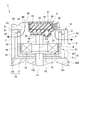
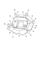
- FIG. 2 is a cross-sectional view taken along the line II-II in FIG. It is a perspective view of a case and a stay concerning an embodiment.
- the rotating electrical machine unit 1 includes a rotating electrical machine 2, a control unit 3, and a fan 4.
- the rotating electrical machine 2 includes a stator 11 and a rotor 12 that is rotatably provided with respect to the stator 11.
- the stator 11 is configured by attaching a plurality of coils 14 to an iron core portion 13.
- the iron core portion 13 includes a plurality of teeth portions (not shown) arranged in the circumferential direction.
- the plurality of coils 14 are wound around each tooth portion. That is, the plurality of coils 14 are arranged in the circumferential direction of the stator 11.
- the rotor 12 includes a rotor body 15 formed in a bottomed cylindrical shape and a plurality of permanent magnets 16 arranged in the circumferential direction of the rotor body 15.
- the plurality of permanent magnets 16 are arranged so that, for example, the magnetic poles of the surface facing the radial direction of the rotor body 15 appear alternately in the circumferential direction of the rotor body 15.
- the rotor body 15 includes a disc-shaped bottom wall portion 17 and a cylindrical peripheral wall portion 18.
- the bottom wall portion 17 is fixed to the rotating shaft 102.
- the peripheral wall portion 18 is provided on the side opposite to the main body portion 101 of the engine 100 from the outer peripheral portion of the bottom wall portion 17.
- the bottom wall portion 17 and the peripheral wall portion 18 can be integrally formed.
- the plurality of permanent magnets 16 are fixed to the rotor body 15.
- the permanent magnet 16 may be fixed to the inner peripheral surface of the peripheral wall portion 18 of the rotor body 15.
- the stator 11 is accommodated in the rotor 12 such that the plurality of coils 14 face the plurality of permanent magnets 16 in the radial direction.
- the rotor 12 is provided so as to rotate together with the rotating shaft 102 of the engine 100.
- An example of the rotating shaft 102 is a crankshaft.
- the rotor 12 of this embodiment is directly fixed to the end of the rotating shaft 102 so that the axis L2 of the rotor 12 coincides with the axis L1 of the rotating shaft 102.
- the rotor 12 may be coupled to the rotating shaft 102 via a transmission mechanism (not shown) such as an endless belt or a gear.
- the rotating electrical machine 2 of the present embodiment is configured as a starter motor that rotationally drives the rotating shaft 102 of the engine 100 with electric power.
- the rotating electrical machine 2 is configured as a generator that generates power by the rotation of the rotating shaft 102 of the engine 100.
- the rotating electrical machine 2 may constitute one or both of a starter motor and a generator.
- the axial direction of the rotating electrical machine 2 is a direction along the axis L ⁇ b> 2 of the rotor 12.
- the control unit 3 is electrically connected to the rotating electrical machine 2 by wiring (not shown) and controls the operation of the rotating electrical machine 2.
- the control unit 3 controls the power supplied to the rotating electrical machine 2 when the rotating electrical machine 2 functions as a starter motor, for example.
- the control unit 3 appropriately adjusts the voltage and current of the power generated by the rotating electrical machine 2 and then charges the generated power to a battery (not shown). Or directly supplied to various electrical components (not shown).
- the external shape of the control unit 3 may be arbitrary, but is formed in a substantially rectangular parallelepiped in this embodiment.
- the control unit 3 includes a control circuit unit 31 and a case 32 that houses the control circuit unit 31.
- the control circuit unit 31 includes an electronic component 34 mounted on a substrate 33. With these electronic components 34 and the like, the control circuit unit 31 can control the operation of the rotating electrical machine 2.
- the shape of the case 32 is not limited to the polygon illustrated in FIG. Examples of the substrate 33 include a rigid substrate, a flexible substrate, and a rigid flexible substrate.
- the inside of the case 32 is filled with resin 35. With this resin 35, the control circuit unit 31 is fixed to the case 32 and the control circuit unit 31 is hermetically or liquid-tightly sealed from the external environment of the control unit 3.
- the control circuit unit 31 is connected to a connector 36 for electrical connection with the above-described battery, various electrical components and the like provided outside the control unit 3. An end portion of the connector 36 protrudes outside the case 32.
- a capacitor 37, a power system component 38, and the like may be mounted on the substrate 33.
- the case 32 of the present embodiment has a notch 39 in which the connector 36 is disposed.
- the stator 11 is fixed to the tip of the protrusion 19 that protrudes from the bottom of the control unit 3.
- the stator 11 and the control unit 3 are fixed to each other after being arranged in the axial direction of the rotating electrical machine 2.
- the wiring which electrically connects the stator 11 and the control unit 3 can be set shorter.
- the stator 11 and the control unit 3 are provided inside the fan 4 so that the wiring for electrically connecting the stator 11 and the control unit 3 can be set shorter.
- the fan 4 has a blade portion 21 in which a plurality of blades 22 are arranged in a cylindrical shape.
- the fan 4 of the present embodiment is a centrifugal fan that rotates about the axis L4 of the fan 4 to flow air from the inner side to the outer side in the radial direction of the blade portion 21.
- the fan 4 is configured to rotate together with the rotor 12. That is, the fan 4 is provided so as to rotate together with the rotating shaft 102 of the engine 100, similarly to the rotor 12 described above.
- the fan 4 has a ring portion 23 integrated with a plurality of blades 22 at an end portion on the side far from the rotation shaft 102 in the axial direction.
- the ring portion 23 is provided over the entire circumference in the circumferential direction of the fan 4.
- the fan 4 of this embodiment is fixed to the rotor 12 so that the axis L4 of the fan 4 coincides with L2 of the rotor 12. That is, the fan 4 is fixed to the rotating shaft 102 of the engine 100 via the rotor 12.
- the rotor body 15 of the rotor 12 has the same diameter as the blade portion 21 of the fan 4, and the rotor body 15 and the blade portion 21 are formed in an integral cylindrical shape.
- the fan 4 may be coupled to the rotating shaft 102 without the rotor 12 interposed therebetween.
- the fan 4 may be connected to the rotary shaft 102 or the rotor 12 via a transmission mechanism (not shown) such as an endless belt or a gear.
- the casing 5 of the present embodiment is configured in a substantially cylindrical shape so as to surround the outside of the fan 4 in the radial direction of the fan 4.
- the casing 5 may be provided not only in an area overlapping the fan 4 but also in an area outside the fan 4.
- the casing 5 is integrated with the main body 101 of the engine 100 on one side in the direction of the axis L ⁇ b> 4 of the fan 4.
- An example of the main body 101 is an engine block.
- the shape of the casing 5 is not limited to a cylindrical shape, and may be at least a cylindrical shape.
- the casing 5 may be configured, for example, by arranging a plurality of rod-like portions 51 arranged at intervals in the circumferential direction of the fan 4 in a substantially cylindrical shape.
- the rod-shaped portion 51 that protrudes from the main body portion 101 of the engine 100 in the axial direction of the fan 4 may constitute the casing 5.
- one end portion of the rod-like portion 51 that is a separate member from the main body portion 101 may be fixed to the main body portion 101 by screwing or the like.
- the casing 5 has an exhaust port 52 for air flowing from the fan 4.
- the exhaust ports 52 may be formed between the plurality of rod-shaped portions 51.
- the range in which the exhaust port 52 is provided in the axial direction of the casing 5 may be a part of the axial range of the casing 5.
- the casing 5 is fixed to a stay 6 that holds the control unit 3 on the other side in the direction of the axis L4 of the fan 4. Thereby, the control unit 3 is fixed to the casing 5 via the stay 6.
- the stay 6 of this embodiment has a stay body 41 that surrounds the case 32.
- the stay main body 41 of the present embodiment is fixed to the casing 5 at the fixing portion 43 by screws or the like.
- the plurality of fixing portions 43 and the plurality of rod-like portions 51 may be provided so as to correspond to each other.
- the fixing portions 43 are arranged at intervals in the circumferential direction of the stay main body 41.
- the stay main body 41 may have a ring shape extending over the entire circumferential direction.
- the stay main body 41 may be formed in an arc shape in which a part in the circumferential direction is cut away.
- the case 32 and the stay 6 are integrally formed.
- the control unit 3 is arranged near the engine 100 in the same manner as the rotating electrical machine 2, the heat of the control circuit section 31 is efficiently released from the case 32 to the stay 6 and is dissipated from the stay 6 to the outside by the fan 4 can do.
- the case 32 is formed integrally with the stay 6, the mechanical strength of the control unit 3 is improved. Even if vibration is transmitted from the main body 101 of the engine 100, no looseness occurs between the case 32 and the stay 6, so that the position of the control unit 3 is stabilized.
- the number of components of the rotating electrical machine unit 1 is reduced, it is possible to reduce the number of manufacturing steps and costs.
- the case 6 formed integrally with the stay 6 and the stay 6 may be made of a material having high thermal conductivity such as aluminum.
- the integrally forming method is not particularly limited, and examples thereof include a casting method such as die casting and a machining method such as cutting.
- the stay 6 includes a plurality of arm portions 42 extending from the case 32 to the stay body 41 in addition to the stay body 41 formed in a ring shape or an arc shape surrounding the case 32. .
- the case 32 of the control unit 3 is disposed inside the fan 4 in the radial direction of the fan 4.
- the plurality of arm portions 42 are disposed inside the fan 4 in the radial direction of the fan 4. In the axial direction of the fan 4, the case 32 and the plurality of arm portions 42 may be outside the fan 4.
- a region without the arm portion 42 between the case 32 and the stay main body 41 is an air inlet 44 of the fan 4.
- the fan 4 rotates, air flows through the air inlet 44 in the gap between the case 32 and the stay main body 41. Thereby, especially the control circuit part 31 of the control unit 3 can be efficiently cooled. Further, the heat of the control unit 3, particularly the control circuit part 31, can be distributed to the plurality of arm parts 42 and released. Since air also flows around the arm portion 42, the heat of the arm portion 42 can be efficiently dissipated into the air. In the present embodiment, the entire case 32 is disposed inside the fan 4 in the radial direction of the fan 4. For this reason, the air passing through the air inlet 44 can effectively cool the outer surface of the case 32.
- At least a portion of the arm portion 42 between the stay main body 41 and the case 32, where the arm portion 42 faces the air inlet 44, is disposed inside the fan 4 in the radial direction of the fan 4. For this reason, the air passing through the air inlet 44 can effectively cool the outer surface of the arm portion 42.
- a portion of the arm portion 42 formed on the main surface of the stay main body 41 may reach the outside of the fan 4 in the radial direction of the fan 4.
- the plurality of arm portions 42 are formed in a plate shape extending in the axial direction of the rotating electrical machine 2.
- the main surface of the arm portion 42 is one surface on both sides or one side in the thickness direction, the normal line of the main surface of the arm portion 42 is perpendicular to the axial direction of the rotating electrical machine 2. Since the main surface of the plate-like arm portion 42 follows the air flow generated when the fan 4 rotates, the heat of the arm portion 42 can be efficiently dissipated into the air.
- the arm part 42 has a large dimension in the axial direction, the connection strength between the case 32 and the stay main body 41 can be improved.
- the fan 4 is disposed on one side of the stay main body 41 in the axial direction of the rotating electrical machine 2, and the plurality of arm portions 42 are in the stay main body 41 in the axial direction. Extending to the other side. As described above, the arm portion 42 is positioned outside the fan 4 in the axial direction of the fan 4, so that the air flow F inside the fan 4 can be prevented from being disturbed by the arm portion 42.
- the stay main body 41 is formed in a plate shape in which the axial direction of the rotating electrical machine 2 is the plate thickness direction.
- the main surface of the stay main body 41 is a surface on both sides or one side in the plate thickness direction.
- the cross section of the stay main body 41 has a shape in which the radial dimension is larger than the axial dimension.
- a plurality of arm portions 42 extend in the axial direction from one main surface of the stay main body 41.
- the stay main body 41 partitions the intake port 44 provided between the case 32 and the stay main body 41 and the exhaust port 52 provided in the casing 5. Therefore, the air flow F is stabilized.
- the end portion of the arm portion 42 on the side far from the case 32 may be formed on the main surface of the stay main body 41. It may be formed on the inner periphery.
- the inner periphery of the stay body 41 is the side facing the outer periphery of the case 32.
- the cross section of the stay body 41 may have a shape in which the axial dimension is larger than the radial dimension.
- the stay main body 41 may have a cylindrical shape or a shape in which a part of the cylindrical circumferential direction is cut out.
- the fixing portion 43 is disposed at a point where the plurality of arm portions 42 extend.
- the connection strength between the stay 6 and the casing 5 can be increased because the arm portion 42 is close to the fixing portion 43.
- the durability of the rotating electrical machine unit 1 can be increased against vibration transmitted from the main body 101 of the engine 100 to the casing 5. Heat transmitted from the main body 101 side of the engine 100 through the casing 5 is efficiently dissipated from the stay main body 41 and the plurality of arm portions 42.
- the stator 11 is an inner stator and the rotor 12 is an outer rotor. Since the rotor 12 is an outer rotor, the structure in which the fan 4 rotating together with the rotor 12 is arranged in combination with the rotor 12 is simplified, and loss can be reduced during rotation.
- the fan 4 can be rationally integrated with the rotor 12 by the rotor 12 being an outer rotor. it can.
- the stator 11 that is an inner stator is fixed to the control unit 3.
- the coil 14 of the stator 11 is energized via wiring.
- the control unit 3 and the stator 11 are more reliably fixed. As described above, as the vibration of the control unit 3 is suppressed, the position of the stator 11 is also stabilized.
- the fan 4 may be disposed outside the rotor 12 in the radial direction of the rotor 12.
- the fan 4 may be directly attached to the rotating shaft 102 of the engine 100 without contacting the rotor 12.
- the air that flows out of the fan 4 may be used for cooling the main body 101 of the engine 100 or a radiator for cooling the engine 100 with water cooling, for example.
- the rotating electrical machine 2 is not limited to a radial gap type rotating electrical machine that is disposed so that the stator 11 and the rotor 12 face each other in the radial direction, and is, for example, an axial gap type that is disposed so that the stator and the rotor face each other in the axial direction. It may be a rotating electric machine. Moreover, the rotary electric machine 2 may comprise only a starter motor, for example, and may comprise only a generator.
Landscapes
- Engineering & Computer Science (AREA)
- Power Engineering (AREA)
- Motor Or Generator Cooling System (AREA)
- Connection Of Motors, Electrical Generators, Mechanical Devices, And The Like (AREA)
Abstract
回転電機ユニットは、ステータ、及び、該ステータに対して回転自在に設けられると共にエンジンの回転軸と共に回転するロータを有し、スタータモータ及び発電機の少なくとも一方を構成する回転電機と、前記回転電機の動作を制御する制御回路部及び前記制御回路部を収容するケースを有するコントロールユニットと、前記ロータと共に回転する円筒状のファンと、前記ファンの外側を囲むケーシングと、前記コントロールユニットを前記ケーシングに固定するステーと、を備え、前記ステーが、前記ケースを囲むリング状又は弧状に形成されて前記ケーシングに固定されたステー本体と、前記ケースから前記ステー本体まで延びる複数の腕部と、を備え、前記ケースと前記ステーとが一体に形成され、前記ケース及び前記複数の腕部が、前記ファンの径方向において前記ファンの内側に配置されている。
Description
本発明は、回転電機ユニットに関する。
従来、車両のエンジン等に設けられる回転電機の動作は、コントロールユニットによって制御されている。例えば、回転電機を始動する際には、コントロールユニットから回転電機に電力が供給される。また、回転電機において発電する際には、回転電機からコントロールユニットに電力が供給される。
一般に、コントロールユニットは熱に弱い電子部品を有する。このため、従来では、回転電機はエンジンの近くに配されるが、コントロールユニットはエンジンから離れた位置に配される。特許文献1には、エンジンにおいて生じる熱やコントロールユニットの自己発熱による熱気の影響を抑制できるように、エンジンルーム内にコントロールユニットを配置する構成が開示されている。
しかしながら、従来のようにコントロールユニットが回転電機から離れた位置に配置されると、コントロールユニットと回転電機とを接続する配線が長くなり、配線における電圧損失が大きくなる、という問題がある。例えば、回転電機を始動する際には、電力をより高い電圧でコントロールユニットから回転電機に供給する必要があるため、消費電力が大きくなってしまう。また、回転電機において発電する際には、発電された電力が配線において無駄に消費され、実質的な発電量が減少してしまう。
一方、上記配線を短くするためには、コントロールユニットを回転電機と同様にエンジンの近くに配する必要がある。しかし、この場合には、コントロールユニットを積極的に冷却するとともに、コントロールユニットの機械的強度を向上する必要がある。
本発明の一態様は、回転電機とコントロールユニットとの間における電圧損失を抑制できると共に、コントロールユニットを効率よく冷却することが可能な回転電機ユニットを提供することを目的とする。
本発明の一態様としての回転電機ユニットは、ステータ、及び、該ステータに対して回転自在に設けられると共にエンジンの回転軸と共に回転するロータを有し、スタータモータ及び発電機の少なくとも一方を構成する回転電機と、前記回転電機の動作を制御する制御回路部及び前記制御回路部を収容するケースを有するコントロールユニットと、前記ロータと共に回転する円筒状のファンと、前記ファンの外側を囲むケーシングと、前記コントロールユニットを前記ケーシングに固定するステーと、を備え、前記ステーが、前記ケースを囲むリング状又は弧状に形成されて前記ケーシングに固定されたステー本体と、前記ケースから前記ステー本体まで延びる複数の腕部と、を備え、前記ケースと前記ステーとが一体に形成され、前記ケース及び前記複数の腕部が、前記ファンの径方向において前記ファンの内側に配置されている。
本発明の一態様によれば、コントロールユニットを回転電機と同様にエンジンの近くに配しても、コントロールユニットのケースがステーと一体に形成されているので、制御回路部の熱を、ケースからステーに効率よく逃がし、ファンによりステーから外部に放散することができる。
また、本発明の一態様によれば、ケースがステーと一体に形成されているので、コントロールユニットの機械的強度が向上される。エンジン本体部から振動が伝わっても、ステーとケースの間で緩みが生じないので、コントロールユニットの位置が安定する。また、回転電機ユニットの構成部品点数が少なくなるため、製造工数やコストの削減を図ることができる。
また、本発明の一態様によれば、ケースとステー本体との間において、腕部のない領域は、ファンの吸気口となる。これにより、コントロールユニットの特に制御回路部を効率よく冷却することができる。また、コントロールユニットの特に制御回路部の熱を、複数の腕部に分散して逃がすことができる。腕部の周りにも空気が流れるため、腕部の熱を効率よく空気中に放散することができる。
また、本発明の一態様によれば、ケースがステーと一体に形成されているので、コントロールユニットの機械的強度が向上される。エンジン本体部から振動が伝わっても、ステーとケースの間で緩みが生じないので、コントロールユニットの位置が安定する。また、回転電機ユニットの構成部品点数が少なくなるため、製造工数やコストの削減を図ることができる。
また、本発明の一態様によれば、ケースとステー本体との間において、腕部のない領域は、ファンの吸気口となる。これにより、コントロールユニットの特に制御回路部を効率よく冷却することができる。また、コントロールユニットの特に制御回路部の熱を、複数の腕部に分散して逃がすことができる。腕部の周りにも空気が流れるため、腕部の熱を効率よく空気中に放散することができる。
以下、図1~3を参照して本発明の実施形態について説明する。
図1,2に示すように、本実施形態に係る回転電機ユニット1は、回転電機2、コントロールユニット3及びファン4を備える。
図1,2に示すように、本実施形態に係る回転電機ユニット1は、回転電機2、コントロールユニット3及びファン4を備える。
回転電機2は、ステータ11、及び、ステータ11に対して回転自在に設けられるロータ12を有する。ステータ11は、鉄心部13に複数のコイル14を取り付けて構成されている。鉄心部13は、周方向に配列された複数のティース部(不図示)を備える。複数のコイル14は、各ティース部に巻き付けられている。すなわち、複数のコイル14は、ステータ11の周方向に配列されている。
ロータ12は、有底円筒状に形成されたロータ本体15と、ロータ本体15の周方向に配列される複数の永久磁石16を備える。複数の永久磁石16は、例えば、ロータ本体15の径方向に向く面の磁極がロータ本体15の周方向に交互に現れるように配列される。本実施形態において、ロータ本体15は、円盤状の底壁部17と、円筒状の周壁部18とを備える。底壁部17は、回転軸102に固定されている。周壁部18は、底壁部17の外周部からエンジン100の本体部101とは反対側に設けられている。底壁部17と周壁部18とは一体に構成することができる。複数の永久磁石16は、ロータ本体15に固定されている。例えば、ロータ本体15の周壁部18の内周面に、永久磁石16が固定されてもよい。ステータ11は、複数のコイル14が複数の永久磁石16と径方向に対向するように、ロータ12内に収容されている。
また、ロータ12は、エンジン100の回転軸102と共に回転するように設けられる。回転軸102としては、例えばクランクシャフトが挙げられる。本実施形態のロータ12は、ロータ12の軸線L2が回転軸102の軸線L1と一致するように、回転軸102の端部に直接固定されている。なお、ロータ12は、無端ベルト、ギヤ等の伝動機構(不図示)を介して、回転軸102と連結されてもよい。ファン4及びロータ12が同軸上に直接連結された場合、回転電機ユニット1の構成部品点数を少なく設定できる。
本実施形態の回転電機2は、エンジン100の回転軸102を電力によって回転駆動するスタータモータとして構成される。また、回転電機2は、エンジン100の回転軸102の回転によって発電する発電機として構成される。回転電機2は、スタータモータ又は発電機の一方又は両方を構成してもよい。回転電機2の軸方向は、ロータ12の軸線L2に沿う方向である。
コントロールユニット3は、不図示の配線によって回転電機2に電気接続され、回転電機2の動作を制御する。コントロールユニット3は、例えば回転電機2をスタータモータとして機能させる際に、回転電機2に供給される電力を制御する。また、コントロールユニット3は、例えば回転電機2が発電機として機能する際に、回転電機2において発電された電力の電圧や電流を適宜調整した上で、発電電力をバッテリ(不図示)に充電したり、各種電気部品(不図示)に直接供給したりする。
コントロールユニット3の外観形状は、任意であってよいが、本実施形態では略直方体に形成されている。コントロールユニット3は、制御回路部31と、制御回路部31を収容するケース32と、を備えている。制御回路部31は、基板33に実装された電子部品34を備えている。これらの電子部品34等により、制御回路部31は、回転電機2の動作を制御することができる。ケース32の形状は、図1に例示する多角形に限らず、円形など任意であってよい。基板33としては、リジッド基板、フレキシブル基板、リジッドフレキシブル基板が挙げられる。
ケース32の内部には、樹脂35が充填されている。この樹脂35により、制御回路部31がケース32に固定されると共に、制御回路部31がコントロールユニット3の外部環境から気密又は液密に封止される。制御回路部31は、コントロールユニット3の外部に設けられる上述のバッテリ、各種電気部品等と電気接続するためのコネクタ36に接続されている。コネクタ36の端部は、ケース32の外部に突出されている。基板33上には、制御系の電子部品34のほかにも、コンデンサ37、パワー系部品38等が実装されてもよい。本実施形態のケース32は、コネクタ36が配される切欠部39を有する。
本実施形態において、ステータ11は、コントロールユニット3の底部から突出する突起部19の先端に固定されている。これにより、ステータ11及びコントロールユニット3が、回転電機2の軸方向に配列された上で互いに固定されている。このため、ステータ11とコントロールユニット3とを電気接続する配線をより短く設定できる。また、ステータ11がコントロールユニット3と共にファン4の内部に設けられることでも、ステータ11とコントロールユニット3とを電気接続する配線をより短く設定できる。
ファン4は、複数の羽根22を円筒状に配列した羽根部21を有する。本実施形態のファン4は、ファン4の軸線L4を中心に回転することで、空気を羽根部21の径方向における内側から外側に流す遠心ファンである。ファン4は、ロータ12と共に回転するように構成されている。すなわち、ファン4は、前述したロータ12と同様に、エンジン100の回転軸102と共に回転するように設けられる。ファン4は、軸方向において回転軸102から遠い側の端部に、複数の羽根22と一体化されたリング部23を有する。リング部23は、ファン4の周方向で全周にわたり設けられている。
本実施形態のファン4は、ファン4の軸線L4がロータ12のL2と一致するように、ロータ12に固定されている。すなわち、ファン4が、ロータ12を介してエンジン100の回転軸102に固定されている。具体的には、ロータ12のロータ本体15がファン4の羽根部21と同じ径寸法であり、ロータ本体15及び羽根部21が一体の円筒状に形成されている。なお、ファン4は、ロータ12を介することなく回転軸102と連結されてもよい。また、ファン4が、無端ベルト、ギヤ等の伝動機構(不図示)を介して、回転軸102又はロータ12と連結されてもよい。
本実施形態のケーシング5は、ファン4の径方向におけるファン4の外側を囲むように略円筒状に構成されている。ファン4の軸方向においては、ケーシング5は、ファン4と重なり合う領域のみならず、ファン4の外側の領域まで設けられてもよい。ケーシング5は、ファン4の軸線L4の方向の一方の側において、エンジン100の本体部101に一体化されている。本体部101としては、例えばエンジンブロックが挙げられる。ケーシング5の形状は、円筒状に限ることはなく、少なくとも筒状に形成されていればよい。
ケーシング5は、例えばファン4の周方向に間隔をあけて配置される複数の棒状部51を略円筒状に配列して構成されてもよい。例えばエンジン100の本体部101からファン4の軸方向に突出する棒状部51がケーシング5を構成してもよい。あるいは本体部101とは別体の部材とされる棒状部51の一端部が、本体部101に対してネジ止め等によって固定されてもよい。
ケーシング5は、ファン4から流される空気の排気口52を有する。例えばケーシング5の周方向において、複数の棒状部51の間にそれぞれ排気口52が構成されてもよい。ケーシング5の軸方向において、排気口52が設けられる範囲は、ケーシング5の軸方向の範囲の一部でもよい。
また、ケーシング5は、ファン4の軸線L4の方向の他方の側において、コントロールユニット3を保持するステー6と固定されている。これにより、コントロールユニット3は、ステー6を介してケーシング5に固定される。本実施形態のステー6は、ケース32を囲むステー本体41を有する。本実施形態のステー本体41は、固定部43において、ケーシング5に対してネジ止め等によって固定されている。例えば、複数の固定部43と複数の棒状部51とがそれぞれ対応するように設けられてもよい。固定部43は、ステー本体41の周方向に間隔をあけて配置されている。ステー本体41は、周方向の全体に及ぶリング状でもよい。ステー本体41が、周方向の一部が切り欠かれた弧状に形成されてもよい。
図3に示すように、本実施形態においては、ケース32とステー6とが一体に形成されている。これにより、コントロールユニット3を回転電機2と同様にエンジン100の近くに配しても、制御回路部31の熱を、ケース32からステー6に効率よく逃がし、ファン4によりステー6から外部に放散することができる。また、ケース32がステー6と一体に形成されているため、コントロールユニット3の機械的強度が向上される。エンジン100の本体部101から振動が伝わっても、ケース32とステー6との間で緩みが生じないので、コントロールユニット3の位置が安定する。また、回転電機ユニット1の構成部品点数が少なくなるため、製造工数やコストの削減を図ることができる。
ステー6及びステー6と一体に形成されるケース32は、例えばアルミニウムなど熱伝導率の高い材料によって構成されてよい。一体形成の手法としては、特に限定されないが、例えば、ダイカスト等の鋳造法、切削等の機械加工法が挙げられる。
本実施形態では、図1に示すように、ステー6は、ケース32を囲むリング状又は弧状に形成されたステー本体41に加えて、ケース32からステー本体41まで延びる複数の腕部42を備える。コントロールユニット3のケース32は、ファン4の径方向においてファン4の内側に配置されている。また、複数の腕部42は、ファン4の径方向においてファン4の内側に配置されている。ファン4の軸方向においては、ケース32及び複数の腕部42がファン4の外側であってもよい。
ケース32とステー本体41との間において、腕部42のない領域は、ファン4の吸気口44となる。ファン4の回転に伴って、空気がケース32とステー本体41との隙間にある吸気口44を通るように流れる。これにより、コントロールユニット3の特に制御回路部31を効率よく冷却することができる。
また、コントロールユニット3の特に制御回路部31の熱を、複数の腕部42に分散して逃がすことができる。腕部42の周りにも空気が流れるため、腕部42の熱を効率よく空気中に放散することができる。
なお、本実施形態においては、ケース32の全体が、ファン4の径方向においてファン4の内側に配置されている。このため、吸気口44を通る空気は、ケース32の外面を効果的に冷却することができる。また、腕部42のうち、少なくとも、ステー本体41とケース32の間において、腕部42が吸気口44に面する部分は、ファン4の径方向においてファン4の内側に配置されている。このため、吸気口44を通る空気は、腕部42の外面を効果的に冷却することができる。腕部42のうちステー本体41の主面上に形成されている部分は、ファン4の径方向においてファン4の外側に達していてもよい。
ケース32とステー本体41との間において、腕部42のない領域は、ファン4の吸気口44となる。ファン4の回転に伴って、空気がケース32とステー本体41との隙間にある吸気口44を通るように流れる。これにより、コントロールユニット3の特に制御回路部31を効率よく冷却することができる。
また、コントロールユニット3の特に制御回路部31の熱を、複数の腕部42に分散して逃がすことができる。腕部42の周りにも空気が流れるため、腕部42の熱を効率よく空気中に放散することができる。
なお、本実施形態においては、ケース32の全体が、ファン4の径方向においてファン4の内側に配置されている。このため、吸気口44を通る空気は、ケース32の外面を効果的に冷却することができる。また、腕部42のうち、少なくとも、ステー本体41とケース32の間において、腕部42が吸気口44に面する部分は、ファン4の径方向においてファン4の内側に配置されている。このため、吸気口44を通る空気は、腕部42の外面を効果的に冷却することができる。腕部42のうちステー本体41の主面上に形成されている部分は、ファン4の径方向においてファン4の外側に達していてもよい。
また、本実施形態においては、複数の腕部42が、回転電機2の軸方向に延びる板状に形成されている。この場合、腕部42の主面は、板厚方向の両側又は片側の一方の面であることから、腕部42の主面の法線は、回転電機2の軸方向に垂直となる。板状の腕部42の主面が、ファン4が回転した際に生じる空気の流れに沿うため、腕部42の熱を効率よく空気中に放散することができる。また、腕部42は軸方向の寸法が大となるため、ケース32及びステー本体41との接続強度も向上することができる。
また、本実施形態においては、図2に示すように、ファン4が、回転電機2の軸方向においてステー本体41の一方側に配置され、複数の腕部42が、当該軸方向においてステー本体41の他方側に延びている。このように、腕部42がファン4の軸方向においてはファン4の外側に位置することで、ファン4の内側における空気の流れFが腕部42により乱されることを抑制することができる。
また、本実施形態においては、ステー本体41が、回転電機2の軸方向を板厚方向とする板状に形成されている。なお、ステー本体41の主面は、板厚方向の両側又は片側の面である。図2に示す例では、ステー本体41の断面が、軸方向の寸法よりも径方向の寸法が大きい形状となっている。
また、複数の腕部42が、ステー本体41の一方の主面から軸方向に延びている。これにより、腕部42がステー本体41の内周のみから径方向に延びている場合と比べて、腕部42とステー本体41との接続強度を高くすることができる。また、図2に示すように、ケース32とステー本体41との間に設けられる吸気口44と、ケーシング5に設けられる排気口52との間が、ステー本体41により仕切られる。そのため、空気の流れFが安定する。
なお、ケース32とステー本体41との間に延びる腕部42において、腕部42のケース32から遠い側の端部は、ステー本体41の主面上に形成されてもよく、ステー本体41の内周に形成されてもよい。ここで、ステー本体41の内周とは、ケース32の外周と対向する側である。ステー本体41の断面が、径方向の寸法よりも軸方向の寸法が大きい形状でもよい。例えばステー本体41が円筒状、又は円筒の周方向の一部を切り欠いた形状であってもよい。
また、複数の腕部42が、ステー本体41の一方の主面から軸方向に延びている。これにより、腕部42がステー本体41の内周のみから径方向に延びている場合と比べて、腕部42とステー本体41との接続強度を高くすることができる。また、図2に示すように、ケース32とステー本体41との間に設けられる吸気口44と、ケーシング5に設けられる排気口52との間が、ステー本体41により仕切られる。そのため、空気の流れFが安定する。
なお、ケース32とステー本体41との間に延びる腕部42において、腕部42のケース32から遠い側の端部は、ステー本体41の主面上に形成されてもよく、ステー本体41の内周に形成されてもよい。ここで、ステー本体41の内周とは、ケース32の外周と対向する側である。ステー本体41の断面が、径方向の寸法よりも軸方向の寸法が大きい形状でもよい。例えばステー本体41が円筒状、又は円筒の周方向の一部を切り欠いた形状であってもよい。
また、本実施形態においては、固定部43が、複数の腕部42の延びる先に配されている。固定部43に腕部42が近接することで、ステー6とケーシング5との接続強度を高くすることができる。エンジン100の本体部101からケーシング5に伝わる振動に対して、回転電機ユニット1の耐久性を高くすることができる。エンジン100の本体部101側からケーシング5を経て伝わる熱が、ステー本体41及び複数の腕部42から効率的に放散される。
また、本実施形態においては、ステータ11がインナーステータであり、ロータ12がアウターロータである。ロータ12がアウターロータとなることで、ロータ12と共に回転するファン4を、ロータ12と組み合わせて配置する構造が簡潔化され、回転の際に損失を低減することができる。
ケース32及び複数の腕部42がファン4の径方向においてファン4の内側に配置される構成において、ロータ12がアウターロータであることにより、ファン4を合理的にロータ12と一体化することができる。
また、本実施形態では、インナーステータとされたステータ11が、コントロールユニット3に固定される。コントロールユニット3から回転電機2に電力を供給する際、配線を介してステータ11のコイル14に通電される。コントロールユニット3とステータ11との間がより確実に固定される。上述したように、コントロールユニット3の振動が抑制されるに伴い、ステータ11の位置も安定する。
以上、本発明の詳細について説明したが、本発明は上述した実施形態に限定されるものではなく、本発明の主旨を逸脱しない範囲において種々の変更を加えることができる。
ファン4は、ロータ12の径方向においてロータ12の外側に配置されてもよい。ファン4は、ロータ12に接触することなく、直接エンジン100の回転軸102に取り付けられてもよい。
ファン4の外側に流れ出た空気は、例えばエンジン100の本体部101や、エンジン100を水冷で冷却するためのラジエータ等の冷却に利用してもよい。
ファン4の外側に流れ出た空気は、例えばエンジン100の本体部101や、エンジン100を水冷で冷却するためのラジエータ等の冷却に利用してもよい。
回転電機2は、径方向においてステータ11とロータ12とが対向するように配置されたラジアルギャップ型回転電機に限らず、例えば軸方向においてステータとロータとが対向するように配置されたアキシャルギャップ型回転電機であってもよい。また、回転電機2は、例えば、スタータモータのみを構成してもよいし、発電機のみを構成してもよい。
1 回転電機ユニット
2 回転電機
3 コントロールユニット
4 ファン
5 ケーシング
6 ステー
11 ステータ
12 ロータ
31 制御回路部
32 ケース
41 ステー本体
42 腕部
43 固定部
100 エンジン
102 回転軸
L1 回転軸の軸線
L2 ロータの軸線
L4 ファンの軸線
2 回転電機
3 コントロールユニット
4 ファン
5 ケーシング
6 ステー
11 ステータ
12 ロータ
31 制御回路部
32 ケース
41 ステー本体
42 腕部
43 固定部
100 エンジン
102 回転軸
L1 回転軸の軸線
L2 ロータの軸線
L4 ファンの軸線
Claims (6)
- ステータ、及び、該ステータに対して回転自在に設けられると共にエンジンの回転軸と共に回転するロータを有し、スタータモータ及び発電機の少なくとも一方を構成する回転電機と、
前記回転電機の動作を制御する制御回路部及び前記制御回路部を収容するケースを有するコントロールユニットと、
前記ロータと共に回転する円筒状のファンと、
前記ファンの外側を囲むケーシングと、
前記コントロールユニットを前記ケーシングに固定するステーと、
を備え、
前記ステーが、前記ケースを囲むリング状又は弧状に形成されて前記ケーシングに固定されたステー本体と、前記ケースから前記ステー本体まで延びる複数の腕部と、
を備え、
前記ケースと前記ステーとが一体に形成され、
前記ケース及び前記複数の腕部が、前記ファンの径方向において前記ファンの内側に配置されていることを特徴とする回転電機ユニット。 - 前記複数の腕部が、前記回転電機の軸方向に延びる板状に形成されていることを特徴とする請求項1に記載の回転電機ユニット。
- 前記ファンが、前記回転電機の軸方向において前記ステー本体の一方側に配置され、
前記複数の腕部が、前記軸方向において前記ステー本体の他方側に延びていることを特徴とする請求項1又は2に記載の回転電機ユニット。 - 前記ステー本体が、前記回転電機の軸方向を板厚方向とする板状に形成され、
前記複数の腕部が、前記ステー本体の一方の主面から軸方向に延びていることを特徴とする請求項1~3のいずれか1項に記載の回転電機ユニット。 - 前記ステー本体が前記ケーシングに固定される固定部が、前記複数の腕部の延びる先に配されていることを特徴とする請求項1~4のいずれか1項に記載の回転電機ユニット。
- 前記ステータがインナーステータであり、前記ロータがアウターロータであることを特徴とする請求項1~5のいずれか1項に記載の回転電機ユニット。
Priority Applications (2)
| Application Number | Priority Date | Filing Date | Title |
|---|---|---|---|
| PCT/JP2017/016950 WO2018198324A1 (ja) | 2017-04-28 | 2017-04-28 | 回転電機ユニット |
| JP2017554619A JP6398019B1 (ja) | 2017-04-28 | 2017-04-28 | 回転電機ユニット |
Applications Claiming Priority (1)
| Application Number | Priority Date | Filing Date | Title |
|---|---|---|---|
| PCT/JP2017/016950 WO2018198324A1 (ja) | 2017-04-28 | 2017-04-28 | 回転電機ユニット |
Publications (1)
| Publication Number | Publication Date |
|---|---|
| WO2018198324A1 true WO2018198324A1 (ja) | 2018-11-01 |
Family
ID=63668474
Family Applications (1)
| Application Number | Title | Priority Date | Filing Date |
|---|---|---|---|
| PCT/JP2017/016950 Ceased WO2018198324A1 (ja) | 2017-04-28 | 2017-04-28 | 回転電機ユニット |
Country Status (2)
| Country | Link |
|---|---|
| JP (1) | JP6398019B1 (ja) |
| WO (1) | WO2018198324A1 (ja) |
Citations (2)
| Publication number | Priority date | Publication date | Assignee | Title |
|---|---|---|---|---|
| WO2016084199A1 (ja) * | 2014-11-27 | 2016-06-02 | 新電元工業株式会社 | 回転電機ユニット |
| WO2017022007A1 (ja) * | 2015-07-31 | 2017-02-09 | 新電元工業株式会社 | 回転電機ユニット |
Family Cites Families (2)
| Publication number | Priority date | Publication date | Assignee | Title |
|---|---|---|---|---|
| JP2004197714A (ja) * | 2002-12-20 | 2004-07-15 | Nissan Motor Co Ltd | モータ |
| JP2008201236A (ja) * | 2007-02-20 | 2008-09-04 | Jtekt Corp | 電動パワーステアリングシステム |
-
2017
- 2017-04-28 WO PCT/JP2017/016950 patent/WO2018198324A1/ja not_active Ceased
- 2017-04-28 JP JP2017554619A patent/JP6398019B1/ja active Active
Patent Citations (2)
| Publication number | Priority date | Publication date | Assignee | Title |
|---|---|---|---|---|
| WO2016084199A1 (ja) * | 2014-11-27 | 2016-06-02 | 新電元工業株式会社 | 回転電機ユニット |
| WO2017022007A1 (ja) * | 2015-07-31 | 2017-02-09 | 新電元工業株式会社 | 回転電機ユニット |
Also Published As
| Publication number | Publication date |
|---|---|
| JPWO2018198324A1 (ja) | 2019-06-27 |
| JP6398019B1 (ja) | 2018-09-26 |
Similar Documents
| Publication | Publication Date | Title |
|---|---|---|
| JP6713208B2 (ja) | モータ内蔵型波動歯車装置 | |
| JP5657117B2 (ja) | 電動機 | |
| JP2013115860A (ja) | 電動モータおよびこれを備える電動ユニット | |
| WO2022239484A1 (ja) | ポンプ装置 | |
| JP6047023B2 (ja) | 電動ポンプ | |
| JP2012223030A (ja) | 電動モータおよびステータ | |
| JP6172877B2 (ja) | 回転電機ユニット | |
| JP2014009676A (ja) | 電動オイルポンプ装置 | |
| JP5270718B2 (ja) | 電力供給ユニット一体型回転電機 | |
| JP5385929B2 (ja) | ファンモータ | |
| JP6398019B1 (ja) | 回転電機ユニット | |
| JP2005098163A (ja) | 磁気結合ポンプ | |
| JP6255566B2 (ja) | 電動機および電気機器 | |
| JP6069684B2 (ja) | 回転電機ユニット | |
| JP2013096283A (ja) | 電動オイルポンプ装置 | |
| WO2020250698A1 (ja) | 電動ポンプ | |
| JP2016111909A (ja) | 回転電機ユニットの配置構造及び回転電機ユニット | |
| KR20150048946A (ko) | 방열 기능을 개선한 캔드 모터 펌프 | |
| JPWO2020016911A1 (ja) | 回転電機 | |
| JP2012085474A (ja) | ファンモータ | |
| JP2006299975A (ja) | 流体ポンプ | |
| JP6402264B1 (ja) | 回転電機ユニット | |
| KR100557886B1 (ko) | 차량용 교류발전기의 회전자 | |
| JP2002165411A (ja) | モータまたは発電機 | |
| KR20140058775A (ko) | 모터의 냉각 구조 |
Legal Events
| Date | Code | Title | Description |
|---|---|---|---|
| ENP | Entry into the national phase |
Ref document number: 2017554619 Country of ref document: JP Kind code of ref document: A |
|
| 121 | Ep: the epo has been informed by wipo that ep was designated in this application |
Ref document number: 17906977 Country of ref document: EP Kind code of ref document: A1 |
|
| NENP | Non-entry into the national phase |
Ref country code: DE |
|
| 122 | Ep: pct application non-entry in european phase |
Ref document number: 17906977 Country of ref document: EP Kind code of ref document: A1 |