WO2018193718A1 - 細胞ハンドリング装置 - Google Patents
細胞ハンドリング装置 Download PDFInfo
- Publication number
- WO2018193718A1 WO2018193718A1 PCT/JP2018/006966 JP2018006966W WO2018193718A1 WO 2018193718 A1 WO2018193718 A1 WO 2018193718A1 JP 2018006966 W JP2018006966 W JP 2018006966W WO 2018193718 A1 WO2018193718 A1 WO 2018193718A1
- Authority
- WO
- WIPO (PCT)
- Prior art keywords
- cells
- cell
- compartment
- head
- control unit
- Prior art date
Links
Images


Classifications
-
- C—CHEMISTRY; METALLURGY
- C12—BIOCHEMISTRY; BEER; SPIRITS; WINE; VINEGAR; MICROBIOLOGY; ENZYMOLOGY; MUTATION OR GENETIC ENGINEERING
- C12M—APPARATUS FOR ENZYMOLOGY OR MICROBIOLOGY; APPARATUS FOR CULTURING MICROORGANISMS FOR PRODUCING BIOMASS, FOR GROWING CELLS OR FOR OBTAINING FERMENTATION OR METABOLIC PRODUCTS, i.e. BIOREACTORS OR FERMENTERS
- C12M33/00—Means for introduction, transport, positioning, extraction, harvesting, peeling or sampling of biological material in or from the apparatus
- C12M33/04—Means for introduction, transport, positioning, extraction, harvesting, peeling or sampling of biological material in or from the apparatus by injection or suction, e.g. using pipettes, syringes, needles
-
- B—PERFORMING OPERATIONS; TRANSPORTING
- B01—PHYSICAL OR CHEMICAL PROCESSES OR APPARATUS IN GENERAL
- B01L—CHEMICAL OR PHYSICAL LABORATORY APPARATUS FOR GENERAL USE
- B01L3/00—Containers or dishes for laboratory use, e.g. laboratory glassware; Droppers
- B01L3/02—Burettes; Pipettes
- B01L3/021—Pipettes, i.e. with only one conduit for withdrawing and redistributing liquids
- B01L3/0217—Pipettes, i.e. with only one conduit for withdrawing and redistributing liquids of the plunger pump type
- B01L3/0237—Details of electronic control, e.g. relating to user interface
-
- B—PERFORMING OPERATIONS; TRANSPORTING
- B01—PHYSICAL OR CHEMICAL PROCESSES OR APPARATUS IN GENERAL
- B01L—CHEMICAL OR PHYSICAL LABORATORY APPARATUS FOR GENERAL USE
- B01L3/00—Containers or dishes for laboratory use, e.g. laboratory glassware; Droppers
- B01L3/50—Containers for the purpose of retaining a material to be analysed, e.g. test tubes
- B01L3/508—Containers for the purpose of retaining a material to be analysed, e.g. test tubes rigid containers not provided for above
- B01L3/5085—Containers for the purpose of retaining a material to be analysed, e.g. test tubes rigid containers not provided for above for multiple samples, e.g. microtitration plates
-
- C—CHEMISTRY; METALLURGY
- C12—BIOCHEMISTRY; BEER; SPIRITS; WINE; VINEGAR; MICROBIOLOGY; ENZYMOLOGY; MUTATION OR GENETIC ENGINEERING
- C12M—APPARATUS FOR ENZYMOLOGY OR MICROBIOLOGY; APPARATUS FOR CULTURING MICROORGANISMS FOR PRODUCING BIOMASS, FOR GROWING CELLS OR FOR OBTAINING FERMENTATION OR METABOLIC PRODUCTS, i.e. BIOREACTORS OR FERMENTERS
- C12M23/00—Constructional details, e.g. recesses, hinges
- C12M23/02—Form or structure of the vessel
- C12M23/12—Well or multiwell plates
-
- C—CHEMISTRY; METALLURGY
- C12—BIOCHEMISTRY; BEER; SPIRITS; WINE; VINEGAR; MICROBIOLOGY; ENZYMOLOGY; MUTATION OR GENETIC ENGINEERING
- C12M—APPARATUS FOR ENZYMOLOGY OR MICROBIOLOGY; APPARATUS FOR CULTURING MICROORGANISMS FOR PRODUCING BIOMASS, FOR GROWING CELLS OR FOR OBTAINING FERMENTATION OR METABOLIC PRODUCTS, i.e. BIOREACTORS OR FERMENTERS
- C12M23/00—Constructional details, e.g. recesses, hinges
- C12M23/50—Means for positioning or orientating the apparatus
-
- C—CHEMISTRY; METALLURGY
- C12—BIOCHEMISTRY; BEER; SPIRITS; WINE; VINEGAR; MICROBIOLOGY; ENZYMOLOGY; MUTATION OR GENETIC ENGINEERING
- C12M—APPARATUS FOR ENZYMOLOGY OR MICROBIOLOGY; APPARATUS FOR CULTURING MICROORGANISMS FOR PRODUCING BIOMASS, FOR GROWING CELLS OR FOR OBTAINING FERMENTATION OR METABOLIC PRODUCTS, i.e. BIOREACTORS OR FERMENTERS
- C12M33/00—Means for introduction, transport, positioning, extraction, harvesting, peeling or sampling of biological material in or from the apparatus
- C12M33/04—Means for introduction, transport, positioning, extraction, harvesting, peeling or sampling of biological material in or from the apparatus by injection or suction, e.g. using pipettes, syringes, needles
- C12M33/06—Means for introduction, transport, positioning, extraction, harvesting, peeling or sampling of biological material in or from the apparatus by injection or suction, e.g. using pipettes, syringes, needles for multiple inoculation or multiple collection of samples
-
- C—CHEMISTRY; METALLURGY
- C12—BIOCHEMISTRY; BEER; SPIRITS; WINE; VINEGAR; MICROBIOLOGY; ENZYMOLOGY; MUTATION OR GENETIC ENGINEERING
- C12M—APPARATUS FOR ENZYMOLOGY OR MICROBIOLOGY; APPARATUS FOR CULTURING MICROORGANISMS FOR PRODUCING BIOMASS, FOR GROWING CELLS OR FOR OBTAINING FERMENTATION OR METABOLIC PRODUCTS, i.e. BIOREACTORS OR FERMENTERS
- C12M41/00—Means for regulation, monitoring, measurement or control, e.g. flow regulation
- C12M41/48—Automatic or computerized control
-
- B—PERFORMING OPERATIONS; TRANSPORTING
- B01—PHYSICAL OR CHEMICAL PROCESSES OR APPARATUS IN GENERAL
- B01L—CHEMICAL OR PHYSICAL LABORATORY APPARATUS FOR GENERAL USE
- B01L2200/00—Solutions for specific problems relating to chemical or physical laboratory apparatus
- B01L2200/06—Fluid handling related problems
- B01L2200/0647—Handling flowable solids, e.g. microscopic beads, cells, particles
-
- B—PERFORMING OPERATIONS; TRANSPORTING
- B01—PHYSICAL OR CHEMICAL PROCESSES OR APPARATUS IN GENERAL
- B01L—CHEMICAL OR PHYSICAL LABORATORY APPARATUS FOR GENERAL USE
- B01L2200/00—Solutions for specific problems relating to chemical or physical laboratory apparatus
- B01L2200/14—Process control and prevention of errors
- B01L2200/143—Quality control, feedback systems
-
- B—PERFORMING OPERATIONS; TRANSPORTING
- B01—PHYSICAL OR CHEMICAL PROCESSES OR APPARATUS IN GENERAL
- B01L—CHEMICAL OR PHYSICAL LABORATORY APPARATUS FOR GENERAL USE
- B01L3/00—Containers or dishes for laboratory use, e.g. laboratory glassware; Droppers
- B01L3/02—Burettes; Pipettes
- B01L3/021—Pipettes, i.e. with only one conduit for withdrawing and redistributing liquids
- B01L3/0217—Pipettes, i.e. with only one conduit for withdrawing and redistributing liquids of the plunger pump type
- B01L3/022—Capillary pipettes, i.e. having very small bore
Definitions
- the present invention relates to a cell handling apparatus provided with a head device for picking cells and moving and releasing the picked cells.
- a single cell, a cell aggregate obtained by three-dimensional aggregation of cells, or a cell mass obtained by agglomerating and culturing a cell fragment may be housed in the wells of microplates having wells arranged in a matrix for processing operations such as observation, confirmation of drug efficacy, inspection or culture.
- Cells accommodated in the well are selected on a dish having a holding recess capable of accommodating cells.
- a group of cells dispersed in a cell suspension is dispensed using a dispensing tip.
- the cell group to be seeded includes cells of various sizes and shapes. From these cells, the cells suitable for the processing operation are selected, for example, by imaging the dish and performing image processing. Selected cells are picked from the dish with a chip capable of sucking and discharging the cells, moved to the microplate, and discharged (released) into the well.
- a cell handling device including a head device for picking cells and moving and releasing the picked cells is used (see, for example, Patent Document 1).
- the wells as the cell transfer destination contain cells in the intended state in order to facilitate subsequent processing operations.
- the processing operation May cause trouble.
- no cell handling device has been proposed that can correct the state of cells as intended in a destination container.
- An object of the present invention is to provide a cell handling apparatus capable of bringing cells into a container as intended in a container having a compartment for containing cells.
- the cell handling device is a cell handling device comprising: a container having a compartment that can accommodate cells; a cell detection unit that detects cells contained in the compartment; and cell picking and picking cells.
- a head device that moves and releases the head, a control unit that controls the operation of the head device, and at least one of the number, properties, and arrangement of cells contained in the compartment based on the detection result of the cell detection unit.
- a determination unit that performs cell state determination.
- the control unit causes the head device to pick all the cells accommodated in the compartment, and picks a part of the cells accommodated in the compartment according to the result of the state determination of the determination unit.
- One operation selected from the operation, the operation of picking a new cell and releasing it to the compartment, and the operation of finishing the processing for the compartment is executed.
- FIG. 1 is a diagram schematically showing a cell moving device to which a cell handling device according to the present invention is applied.
- FIG. 2A is a top view of a dish provided in the sorting container used in the cell transfer device
- FIG. 2B is a cross-sectional view taken along the line IIB-IIB in FIG.
- FIG. 3A is a perspective view of a microplate used in the cell transfer device
- FIG. 3B is a cross-sectional view of the microplate.
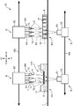
- FIG. 4 is a diagram showing the relationship between the head unit, microplate, and camera unit in the cell transfer device.
- FIG. 5 is a block diagram showing an electrical configuration of the cell transfer device.
- FIG. 1 is a diagram schematically showing a cell moving device to which a cell handling device according to the present invention is applied.
- FIG. 2A is a top view of a dish provided in the sorting container used in the cell transfer device
- FIG. 2B is a cross-sectional view taken along the line IIB-
- FIG. 6 is a flowchart illustrating an example of the work selection process of the head device by the main control unit.
- 7A to 7D are diagrams showing an example of the cell handling operation.
- 8A to 8C are diagrams showing an example of the cell handling operation.
- 9A to 9E are diagrams showing an example of the cell handling operation.
- 10A to 10C are diagrams showing an example of the cell handling operation.
- FIG. 11 is a diagram illustrating an example of a cell handling operation.
- 12A and 12B are diagrams showing an example of the cell handling operation.
- 13A and 13B are diagrams illustrating an example of the cell handling operation.
- 14A to 14D are diagrams showing an example of the cell handling operation.
- FIGS. 15A to 15C are diagrams showing an example of the cell handling operation.
- FIGS. 16A to 16C are diagrams showing an example of the cell handling operation.
- FIGS. 17A to 17C are diagrams showing an example of the cell handling operation.
- a cell, a cell mass, a cell aggregate (spheroid) or the like derived from a living body is handled.
- a cell aggregate derived from a living body is formed by aggregating several to several hundred thousand cells. Therefore, the size of the cell aggregate is various.
- Cell aggregates formed by living cells are almost spherical, but if some of the cells that make up the cell aggregates are altered or become dead cells, the shape of the cell aggregate is distorted, or The density may be non-uniform.
- cell C For testing in the fields of biotechnology and medicine, pick a usable cell aggregate from a plurality of cell aggregates of various shapes carried on a dish on a sorting stage with a chip, and use this to microplate A cell handling device (cell transfer device) that moves to release is used. In the microplate, various processes such as observation, confirmation of drug efficacy, inspection, and culture are performed on the cell aggregates.
- cell C is simply used to include the cell aggregates as described above.
- FIG. 1 is a diagram schematically showing an overall configuration of a cell transfer device S to which a cell handling device according to the present invention is applied.
- a cell moving device S that moves cells C between two containers is illustrated.
- the X and Z directions shown in FIG. 1 are, for example, the left and right directions and the up and down direction, + X is rightward, -X is leftward, + Z is upward, and -Z is downward.
- the direction orthogonal to both the X direction and the Z direction is the Y direction, for example, the front-rear direction.
- the cell transfer device S includes a translucent base 1 having a horizontal placement surface (upper surface), and a camera unit 5 (part of the cell detection unit / imaging device) disposed on the lower side of the base 1. And a head unit 6 (head device) disposed on the upper side of the base 1.
- a sorting container 11 having a dish 2 (cell holder) is placed on the first placement position P1 of the base 1, and a microplate 4 (container) is placed on the second placement position P2.
- the head unit 6 includes a head group 6H on which a chip 12 (part of a head device) that sucks and discharges cells C is mounted and includes a plurality of heads 61 that can move in the Z direction.
- the camera unit 5 and the head unit 6 are movable in the X direction and the Y direction.
- the dish 2 and the microplate 4 are placed on the upper surface of the base 1 within the movable range of the head unit 6.
- the cell transfer device S sucks the cells C individually from each of the plurality of chips 12 from the dish 2 of the sorting container 11 that holds a large number of cells C, and moves the cells C to the microplate 4. It is an apparatus for discharging cells C from a plurality of chips 12 simultaneously or individually to the microplate 4 (well 41). Hereinafter, each part of the cell transfer device S will be described.
- the base 1 is a rectangular flat plate having a predetermined rigidity and part or all of which is made of a translucent material.
- a preferred base 1 is a glass plate.
- the sorting container 11 is a container from which the cells C move, stores the medium L, and holds the cell sorting dish 2 in a state of being immersed in the medium L.
- the dish 2 is a plate for holding the cells C, and has a plurality of holding recesses 3 (holding portions) capable of individually containing and holding the cells C on the upper surface.
- the medium L is not particularly limited as long as it does not deteriorate the properties of the cells C, and can be appropriately selected depending on the type of the cells C.
- the sorting container 11 has a rectangular upper opening 11H on the upper surface side.
- the upper opening 11H is an opening for loading the cells C and picking up the sorted cells C.
- the dish 2 is disposed below the upper opening 11H.
- the sorting container 11 and the dish 2 are made of a translucent resin material or glass. This is because the cells C carried on the dish 2 can be observed by the camera unit 5 arranged below the sorting container 11.
- a plurality of cells C dispersed in a cell culture solution are injected into the sorting container 11 from a dispensing chip (not shown).
- the dispensing tip aspirates the cell culture solution together with the cells C from a container that stores a cell culture solution containing a large amount of cells C, and holds it in the dispensing tip. Thereafter, the dispensing tip is moved to the upper position of the sorting container 11 and accesses the upper surface of the dish 2 through the upper opening 11H. Then, with the tip opening of the dispensing tip immersed in the medium L of the sorting container 11, the cells C held in the dispensing tip are discharged onto the dish 2 together with the cell culture solution.
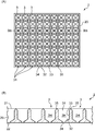
- FIG. 2A is a top view of the dish 2
- FIG. 2B is a cross-sectional view taken along the line IIB-IIB in FIG. 2A.
- the dish 2 includes a dish body 20 and a plurality of holding recesses 3 formed in the dish body 20.
- the dish body 20 is made of a flat plate member having a predetermined thickness, and has an upper surface 21 and a lower surface 22.
- the holding recess 3 has a cell C receiving opening (opening 31) on the upper surface 21 side.
- the dish 2 is immersed in the medium L in the sorting container 11. Specifically, the upper surface 21 of the dish body 20 is immersed in the culture medium L in the sorting container 11, while the lower surface 22 is held in the sorting container 11 in a state of being spaced from the bottom plate of the sorting container 11. (See FIG. 1).
- Each holding recess 3 includes an opening 31, a bottom 32, a cylindrical wall 33, a hole 34, and a boundary 35.
- the opening 31 is a square opening provided on the upper surface 21 and has a size that allows the tip opening t of the sorting chip 12 to enter.
- the bottom 32 is located inside the dish body 20 and near the lower surface 22.
- the bottom 32 is an inclined surface that is gently inclined downward toward the center (the center of the square).
- the cylindrical wall surface 33 is a wall surface extending vertically downward from the opening 31 toward the bottom 32.
- the hole 34 is a through hole that vertically penetrates between the center of the bottom 32 and the lower surface 22.
- the boundary portion 35 is a portion that is located on the upper surface 21 and serves as an opening edge of each holding recess 3, and is a ridge line that partitions the holding recesses 3.
- each holding recess 3 define an accommodation space 3H that accommodates the cells C. It is contemplated that one cell C is generally accommodated in the accommodation space 3H.
- the hole 34 is provided in order to let small cells and impurities other than the desired size escape from the accommodation space 3H. Therefore, the size of the hole 34 is selected so that cells C having a desired size cannot pass through and small cells or impurities other than the desired size can pass therethrough. As a result, the cells C to be sorted are trapped in the holding recess 3, while impurities and the like fall from the hole 34 to the bottom plate of the sorting container 11.
- the microplate 4 is a container to which the cells C are moved, and has a plurality of wells 41 (compartments that can contain the cells) into which the cells C are discharged.
- the well 41 is a hole with a bottom opened on the upper surface of the microplate 4.
- a single well 41 contains a necessary number of cells C together with the medium L.
- the microplate 4 is also made of a translucent resin material or glass. This is because the cell C carried in the well 41 can be observed by the camera unit 5 arranged below the microplate 4.
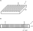
- FIG. 3A is a perspective view showing an example of the microplate 4.
- the microplate 4 includes a plate body 40 and a plurality of wells 41 arranged in a matrix on the plate body 40. Since the tip opening t of the chip 12 enters the well 41 when the cells C are discharged, each well 41 has an opening diameter that allows the chip 12 to enter with a margin.
- the reference microplate has a predetermined vertical ⁇ horizontal size (vertical 85.48 mm ⁇ horizontal 126 mm) and has a predetermined number of wells.
- a general number of wells is 24 ⁇ 16 (384 wells), and these wells are arranged in a matrix at a predetermined pitch.
- FIG. 3B is a cross-sectional view of a 384 well microplate 4. As shown in the drawing, 24 wells 41 are arranged at an equal well pitch 4P in the longitudinal direction of the microplate 4 (16 in the lateral direction).
- the camera unit 5 acquires an image of the cell C held in the holding recess 3 of the dish 2 or the well 41 (compartment) of the microplate 4 from the lower surface side.
- the lens unit 51 and the camera A main body 52 is provided.
- the camera unit 5 functions as a part of a cell detection unit that detects the cells C accommodated in the well 41.
- the lens unit 51 is an objective lens used in an optical microscope, and includes a lens group that forms an optical image with a predetermined magnification and a lens barrel that houses the lens group.
- the camera body 52 includes an image sensor such as a CCD image sensor.
- the lens unit 51 forms an optical image of the imaging object on the light receiving surface of the imaging element.
- the camera unit 5 is movable in the X direction below the base 1 along a guide rail 5G extending in the left-right direction parallel to the base 1. Although not shown in FIG. 1, the camera unit 5 is also movable in the Y direction. Further, the lens unit 51 is movable in the Z direction for the focusing operation.
- the head unit 6 is provided to move the cells C from the dish 2 to the microplate 4, and includes a head group 6H composed of a plurality of heads 61 and a head body 62 to which the head group 6H is assembled.
- a tip 12 that sucks and discharges cells C is attached to the tip of each head 61.
- the head main body 62 holds the head 61 so as to be movable up and down in the + Z and ⁇ Z directions, and is movable in the + X and ⁇ X directions along the guide rail 6G.
- the head main body 62 can also move in the Y direction.
- the head unit 6 functions as a head device that picks the cells C (suction by the chip 12) and moves and releases the picked cells C (discharge by the chip 12).
- the head 61 is formed of a hollow rod provided with a negative pressure generating mechanism.
- a piston mechanism is mounted in the hollow portion of the head 61, and suction force and discharge force are applied to the tip opening t of the chip 12 by the operation of the piston mechanism.
- the head main body 62 incorporates a power unit of the piston mechanism, an elevating mechanism for moving the head 61 in the vertical direction, and a power unit (a head drive unit 64 described later).
- FIG. 4 is a diagram showing a specific example of the head unit 6, and is a diagram showing a relationship between the microplate 4 and the camera unit 5.
- the head group 6H is exposed downward from the lower end side ( ⁇ Z side) of the head main body 62.
- FIG. 4 illustrates a head group 6H including eight heads 61 arranged linearly in the X direction. Further, in FIG. 4, one head 61 is lowered, and the chip 12 mounted on the head 61 is accessing one well 41 of the microplate 4 for picking or releasing the cells C. It is shown. Prior to this picking or release, the well 41 is imaged by the camera unit 5, and the number, nature and arrangement of the cells C moved from the microplate 4 and accommodated in the well 41 are confirmed. Thereafter, the chip 12 picks (suctions) the target cell C or releases (discharges) a new cell.
- the plurality of chips 12 mounted on the plurality of heads 61 are arranged in the X direction at a predetermined chip arrangement pitch 12P.
- the chip arrangement pitch 12P is n times the well pitch 4P of the wells 41 in the microplate 4 (n is an integer of 1 or more).
- n is an integer of 1 or more.
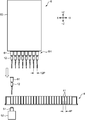
- FIG. 5 is a block diagram showing an electrical configuration of the cell transfer device S.
- the cell moving device S includes a control unit 7 that controls the movement of the head unit 6, the elevation of the head 61, the suction and discharge operation of the cell C, the movement and imaging operation of the camera unit 5, and the like.
- the cell moving device S includes a camera axis drive unit 53 as a mechanism for horizontally moving the camera unit 5, a servo motor 54 as a drive source for moving the lens unit 51 up and down, and a head unit axis drive as a mechanism for horizontally moving the head unit 6.
- the head drive unit 64 is provided as a mechanism for moving the head 63 up and down, and a mechanism for performing suction and discharge operations.
- the camera axis drive unit 53 includes a drive motor that horizontally moves the camera unit 5 along the guide rail 5G.
- a ball screw is laid along the guide rail 5G, the camera unit 5 is attached to a nut member screwed to the ball screw, and the drive motor rotates the ball screw forward or backward. In this mode, the camera unit 5 is moved to the target position.
- the servo motor 54 moves in the vertical direction with a predetermined resolution through a power transmission mechanism (not shown) by rotating in the forward or reverse direction. By this movement, the focal position of the lens unit 51 is adjusted to the cell C accommodated in the well 41. 5, the microplate 4 itself or the stage (base 1) on which the microplate 4 is placed is moved up and down by the servo motor 54 instead of the lens unit 51. Also good.
- the head unit shaft drive unit 63 includes a drive motor that moves the head unit 6 (head body 62) along the guide rail 6G.
- a preferable aspect is an aspect in which a ball screw and a nut member are provided, and the drive motor rotates the ball screw forward or backward.
- the head main body 62 is moved in two directions XY, the first ball screw (X direction) along the guide rail 6G and the movement attached to the first nut member screwed to the first ball screw are mounted.
- a second ball screw (Y direction) mounted on the plate is used. In this case, the head main body 62 is attached to a second nut member screwed into the second ball screw (the camera shaft driving unit 53 is also the same).
- the head driving unit 65 is a power unit for the lifting mechanism and a power unit (for example, a motor) for driving the piston mechanism, and is built in the head main body 62.
- the lifting mechanism moves the head 61 up and down between a lowered position where the head 61 extends downward from the head body 62 and a raised position where most of the head 61 is accommodated in the head body 62.
- the power unit of the piston mechanism raises and lowers the piston member disposed in the head 61 to generate a suction force and a discharge force at the tip opening t of the chip 12.
- the control unit 7 is composed of a microcomputer or the like, and by executing a predetermined program, an axis control unit 71, a head control unit 72, an imaging control unit 73, an image processing unit 74 (part of a cell detection unit), a determination It functions so as to include a unit 75, a storage unit 76, and a main control unit 77 (control unit).
- the axis control unit 71 controls the operation of the head unit axis driving unit 63. That is, the axis control unit 71 controls the head unit shaft driving unit 63 to move the head unit 6 to a predetermined target position in the horizontal direction. Movement of the head 61 (chip 12) between the sorting container 11 and the microplate 4, positioning in the vertical direction with respect to the holding recess 3 of the dish 2, and in the vertical direction with respect to the well 41 of the microplate 4 to be ejected Positioning and the like are realized by controlling the head unit shaft drive unit 64 by the shaft control unit 71.
- the head control unit 72 controls the head driving unit 64.
- the head control unit 72 controls the power unit for the lifting mechanism of the head driving unit 64 to raise and lower the head 61 to be controlled toward a predetermined target position. Further, the head control unit 72 generates a suction force or a discharge force at the tip opening portion t of the chip 12 at a predetermined timing by controlling the power unit of the piston mechanism for the head 61 to be controlled.
- the imaging control unit 73 controls the camera axis driving unit 53 to control the operation of moving the camera unit 5 along the guide rail 5G.
- the imaging control unit 73 controls the imaging operation (exposure amount, shutter timing, etc.) of the dish 2 or the microplate 4 by the camera unit 5.
- the imaging control unit 71 gives a control pulse for moving the lens unit 51 in the vertical direction at a predetermined pitch (for example, several tens of ⁇ m pitch) to the servo motor 54 for the focusing operation.
- the image processing unit 74 performs image processing such as edge detection processing and pattern recognition processing with feature amount extraction on the image data acquired by the camera body 52.
- the image processing unit 74 recognizes the presence (number) of cells C on the dish 2 (holding recesses 3) on the image based on the image of the dish 2 after the cells C are dispensed, and the distribution of the cells C.
- a process for recognizing (placement), a process for recognizing properties such as the size, shape, and color tone of the cell C are executed.
- the image processing unit 74 executes processing for recognizing the number, arrangement, and properties of the cells C accommodated in the well 41 based on the image of the well 41 to which the cells C have been moved.
- the determination unit 75 determines the state of the cell C based on the detection result of the cell C by the camera unit 5 and the image processing unit 74. That is, the determination unit 75 determines the number of cells C existing in one holding recess 3 or the well 41 and the arrangement of the cells C based on the recognition processing result of the cells C by the image processing unit 74 on the image data acquired by the camera unit 5.
- the state of the cell C including the properties such as the size, shape, and color tone of the cell C is determined.
- the well 41 based on the number of cells C, it is determined whether the number of cells C to be accommodated in one well 41 is excessive or insufficient. Further, based on the arrangement of the cells C, whether or not the plurality of cells C are arranged at a predetermined distance in the well 41, or at which position in the well 41 the cells C are in contact (picking is performed). Whether or not it is easy).
- the determination unit 75 determines whether or not the determination target cell C satisfies a predetermined criterion for the property. For example, a determination of “No” is made for the cell C whose size is too large or too small. A determination of “No” is made for a cell C whose shape is extremely distorted, or a cell C having a color tone that seems to be dead or unhealthy.
- the storage unit 76 stores various setting values, data, programs, etc. in the cell transfer device S. In addition, the storage unit 76 also stores data related to the determination criterion of the cell C. For example, the reference data regarding the size range, shape, color, and other properties of the cell C that the determination unit 75 determines to be “good”, and the cell interval that is the determination criterion for selecting either simultaneous suction or individual suction of the cell C Memorize the distance.
- the main control unit 77 comprehensively controls the operations of the camera unit 5 and the head unit 6 (head device).
- the main control unit 77 picks up the image of the dish 2 in which the cells C are seeded at the first placement position P1 (FIG. 1) where the sorting container 11 is placed, and sorts the cells C (good quality cells C) to be moved.
- the camera unit 5 and the head unit 6 are controlled through the axis control unit 71, the head control unit 72, and the imaging control unit 73 so that the selected cells C are picked.
- the main control unit 77 releases the picked cell C to the well 41, images the well 41, and the cells C in each well as intended at the second placement position P2 where the microplate 4 is placed.
- the camera unit 5 and the head unit 6 are controlled so as to perform a correction process for forming a state of being accommodated in 41.
- the dispensing operation of the cells C to the sorting container 11 is executed.
- a plurality of cells C dispersed in a cell culture solution are injected into a sorting container 11 from a dispensing tip (not shown). That is, the cells C are spread on the dish 2.
- the axis control unit 71 controls the camera axis driving unit 53 to move the camera unit 5 below the sorting container 11 along the guide rail 5G. Then, the imaging control unit 73 controls the camera unit 5 and images the cell C carried on the dish 2. The acquired image data is subjected to predetermined image processing by the image processing unit 74. Thereafter, the determination unit 75 determines to select the cells C (good quality cells C) to be moved. The sorted cell C is treated as a picking target by the chip 12 and its coordinate position is obtained.
- the shaft control unit 71 controls the head unit shaft driving unit 64 to move the head unit 6 over the sorting container 11. Then, the head control unit 72 controls the head driving unit 64, the head 61 is lowered, and the tip opening t of the chip 12 accesses the upper surface of the dish 2 through the upper opening 11H. At this time, XYZ coordinate information indicating the position of the cell C to be moved is given to the axis control unit 71 and the head control unit 72, and the chip 12 accesses the holding recess 3 in which the cell C is carried.
- the head drive unit 64 generates a suction force on the head 61. Thereby, the target cell C is sucked into the chip 12 together with the medium L from the dish 2 (holding recess 3) (picking of the cell C). Thereafter, the head 61 is raised, and the head unit 6 is moved to a position above the microplate 4. When the head unit 6 reaches above the microplate 4, the head 61 is lowered again until the tip opening t of the chip 12 enters the well 41 of the microplate 4. Then, the head driving unit 64 generates a discharge force in the head 61, and the cells C in the chip 12 are discharged together with the medium L into the well 41. The discharge state of these cells C into the well 41 is confirmed by imaging the microplate 4 (well 41) by the camera unit 5.
- the accommodation state of the cell C in the well 41 is recognized based on the image acquired by the imaging. Then, a correction operation is performed to correct each well 41 so that cells are accommodated as intended.
- the sorting operation on the dish 2 side may cause a case where the cell C is not accommodated in each well 41 as intended even though the cell selection step has been performed in advance.
- the factors include leakage of suction of the cells C from the dish 2, unintentional mixing of cells and contaminants, insufficient discharge into the well 41, damage of the cells C during movement, and the like.
- the correction operation is, for example, an operation for setting a predetermined number of cells that satisfy a predetermined determination criterion to be accommodated in the predetermined well 41.
- the main control unit 77 causes the head unit 6 to execute a predetermined correction operation on each well 41 to which the cell C has been moved, according to the result of the state determination by the determination unit 75. Specifically, the main control unit 77 causes the head unit 6 to execute one operation selected from the following operations 1 to 4 on one target well 41. -Operation 1; an operation of picking (suctioning) all the cells C accommodated in the well 41. Operation 2; an operation of picking a part of the cell C accommodated in the well 41. -Operation 3: An operation of picking a new cell C and releasing (discharging) it into the well 41. Operation 4; operation for finishing the processing for the well 41.
- the operation 1 is, for example, a picking operation executed when all of the cells C moved to the target well 41 do not satisfy a predetermined determination criterion, specifically when all the cells C are defective. It is.
- Operation 2 is a case where a plurality of cells C are moved to the target well 41, and unnecessary cells C are removed from them, or necessary cells C are taken out and moved to other wells 41 or other containers.
- Picking operation for In the operation 3 when the required number of cells C are not accommodated in the target well 41, the cell C picked in the other well 41 (cell C picked in the operation 2) or the cell C procured elsewhere is selected as the target well 41. It is an operation to add to.
- the operation 4 is selected when it is confirmed that the cell C is accommodated in the target well 41 as intended.
- the operation 4 is, so to speak, an operation in which the head unit 6 passes through the target well 41 and does not actually involve a substantial operation.
- the main control unit 77 causes the head unit 6 to execute any one of the operations 1 to 3 or does not cause the head unit 6 to perform processing on one target well 41. Make a decision.
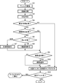
- FIG. 6 is a flowchart showing an example of operation selection processing of the head unit 6 by the main control unit 77.
- the main control unit 77 causes the camera unit 5 to image the well 41 containing the cells C via the imaging control unit 73 (step S1).
- the image processing unit 74 performs image processing on the acquired image data to recognize the cell C (step S2), and then the determination unit 75 determines the state of the cell C (step S3).
- the above steps S1 and S2 may be executed in advance for all the wells 41 included in the microplate 4 so that the data is temporarily stored in the storage unit 76. Alternatively, the steps S1 to S3 and the following steps may be executed for each well 41.
- the main control unit 77 determines whether correction processing such as removal or addition of the cells C is necessary for the target well 41 based on the state determination result by the determination unit 75 (step S4).
- the main control unit 77 determines that the correction process is unnecessary (NO in step S4), and sets the processed flag in association with the identification symbol of the target well 41. (Step S11). This process corresponds to the selection of “Operation 4”.
- the main control unit 77 determines whether or not the cells C need to be removed from the target well 41 (step S5). If more than the necessary number of cells C are stored in the target well 41 or defective cells C are contained, it is determined that cell removal is necessary (YES in step S5). In this case, the main control unit 77 determines whether a part of the cells C may be removed or whether all of them need to be removed (step S6). If it is necessary to remove all the cells C, the whole cell removal operation corresponding to the “operation 1” is selected (step S7). On the other hand, if only part of the cells C need to be removed, the whole cell removal operation corresponding to the “operation 2” is selected (step S8).
- step S9 determines whether it is necessary to add the cell C to the target well 41 (step S9).
- the above “operation 3”. Is selected (step S10).
- This cell addition operation may use the chip 12 from which steps S7 and S8 have been removed, or may use another chip 12 that picks and holds a non-defective cell C in another well 41. . If it is not necessary to add cells (NO in step S9), step S10 is skipped.
- step S11 a processed flag is assigned in association with the identification symbol of the target well 41 (step S11). Then, it is confirmed whether or not the well 41 requiring correction processing remains (step S12). If it remains (YES in step S12), the process returns to any of steps S1, S2 or S3, and the main control unit 77 performs the same process for the next well 41. If it does not remain (NO in step S12), the process ends.
- FIGS. In these drawings, one or two wells 41 are schematically shown.
- the well 41 having a hemispherical bottom surface is illustrated, but the bottom surface may be a flat surface or a tapered surface.
- the cells C are dispersed and held in the medium L (liquid) in the well 41, but the description of the medium L is omitted in FIGS.
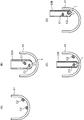
- Example 1> 7A to 7D are diagrams showing Example 1 of cell handling.
- Example 1 shows a specific example of the whole cell removal in the above operation 1 (step S7).
- FIG. 7A it is assumed that two cells C1 and C2 are accommodated in one well 41 to be corrected. Both the cells C1 and C2 are defective products that are determined to not satisfy the predetermined determination criterion by the determination unit 75, and are cells that need to be removed.
- the cell C1 is located near the center of the bottom surface of the well 41, and the cell C2 is located near the edge of the hemispherical bottom surface.
- the two cells C1 and C2 may be aspirated at a time by one aspiration operation of the chip 12 (at once), or the cells C1 and C2 are each aspirated, and one by one on the chip 12. Suction may be performed sequentially (individual suction).
- FIG. 7B shows an example of the former suction at a time.
- a large-diameter chip 12A having a large opening diameter at the tip opening t and a large chip inner diameter is used.
- a suction force is easily generated in the vicinity of the tip opening t in a relatively wide range, and even the cells C1 and C2 that are separated from each other can be sucked at the same time.
- the main controller 77 lowers the head 61 so that the tip opening t of the large-diameter tip 12A enters the well 41, and generates a suction force at the tip opening t. Thereby, two cells C1 and C2 can be held together with the medium in the large-diameter chip 12A.
- FIGS. 7C and 7D show examples of the latter individual suction.
- a small-diameter tip 12B having a small opening diameter at the tip opening t and a small tip inner diameter is used.
- the main control unit 77 first aligns the tip opening t of the small-diameter tip 12B with the cell C1 and sucks the cell C1, as shown in FIG. 7C.
- the head main body 62 is slightly moved to align the tip opening t with the cell C2, and the cell C2 is sucked.
- two cells C1 and C2 can be held in one small-diameter chip 12B by two suction operations.
- even the small-diameter chip 12B may be sucked simultaneously.
- the cells C that do not satisfy the determination criteria are removed from the well 41, so that the well 41 can be in a reset state. Therefore, it is possible to correct the state in which the intended cell C is accommodated in the well 41 by, for example, reintroducing a new cell C that satisfies the above-described determination criteria into the well 41.
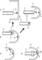
- Example 2> 8A to 8C are diagrams showing Example 2 of cell handling.
- the second embodiment is a modification of the first embodiment, and is attached to different heads 61 in the operation of individually sucking a plurality of cells C1 and C2 (the operations in FIGS. 7C and 7D).
- tip for picking is shown.
- the target well 41 contains two cells C1 and C2 to be picked.
- the first chip 12-1 mounted on one head and the second chip 12-2 (other head device) mounted on the other head 61 are used.
- the tip opening t of the first chip 12-1 is aligned with the cell C1, and the cell C1 is aspirated.
- the head main body 62 is slightly moved to align the tip opening t of the second chip 12-2 with the cell C2 and suck the cell C2.
- two cells C1 and C2 can be held in each chip by one suction operation by the first chip 12-1 and the second chip 12-2.
- the main control unit 77 picks all the cells C to be removed on one chip 12 (example in FIG. 7). It is desirable to select whether the cells C to be shared and removed by the plurality of chips 12 are picked (example in FIG. 8). Thereby, it is possible to diversify the picking and releasing patterns of the cells C, and to improve the efficiency of the work. For example, in the example of FIG. 8, when the cells C1 and C2 are both non-defective, when there are a plurality of other wells 41 in which only one non-defective cell C is present, the wells 41 are moved to the well 41. 1.
- the second chips 12-1 and 12-2 can be accessed to add cells C1 and C2, respectively. Examples 1 and 2 can also be applied to the case where there are a plurality of cells to be removed in the partial cell removal in the operation 2 (step S8).
- FIGS. 9A to 9E are diagrams showing Example 3 of cell handling.
- the third embodiment is applied exclusively to partial cell removal in the operation 2 (step S8).
- FIG. 9A two cells C1 and C2 are accommodated in one well 41 to be corrected, and cell C2 (a part of a plurality of cells) is selected as a picking target.
- cell C2 (a part of a plurality of cells) is selected as a picking target.
- the determination unit 75 arranges the two cells C1 and C2 at a predetermined distance? Determine whether or not.
- the predetermined distance means that when the tip opening t of the chip 12 is approached to a cell to be picked and a suction force is generated, cells existing around the target cell are transferred to the chip 12. It is a distance without suction.
- the determination unit 75 determines that the distance d1 of the cell C1 with respect to the cell C2 to be picked satisfies the predetermined distance.
- the main control unit 77 aligns the tip opening t of the chip 12 with the cell C2 in the well 41 and sucks the cell C2 (picking of some cells). / Individual suction operation).
- the main control unit 77 collects (discards) the unnecessary cell as shown in FIG. 9C.
- the chip 12 (with the head main body 62) holding the cells C2 is moved to the collection container 42 to be discharged, and the cells C2 are discharged into the collection container 42.
- the main control unit 77 accesses the other chip 12 holding the cell C3 that satisfies the above-described determination criteria, and accesses the well 41 from which the cell C2 has been removed. C3 is discharged into the well 41.
- the operation in FIG. 9D corresponds to the above operation 3 (step S10).
- the operation process of FIG. Is an operation of selectively picking.
- the collection container 42 shown in FIG. 9C is replaced with a container for collecting necessary cells, and the operation in FIG. 9D is not executed.
- the cells C2 may be discharged to other wells 41 where the number of cells is insufficient (see Example 4 described below).
- FIG. 9E shows that two cells C1 and C2 are close to each other in the well 41, and the determination unit 75 determines that the distance d2 of the cell C1 with respect to the cell C2 to be picked is The case where it is determined that the distance is not satisfied is illustrated.
- the main control unit 77 causes, for example, the cells C1 and C2 to be sucked into the chip 12 by one suction operation and discharged to the collection container 42 for disposal.
- the medium in the well 41 may be agitated by alternately generating a suction force and a discharge force at the tip opening t.
- Example 4 when a plurality of cells C are arranged at a predetermined distance in the well 41, some of the cells C are picked individually. For this reason, for example, it becomes possible to pick up only unnecessary cells while leaving the necessary cells in the well 41. For such a well 41, it is only necessary to add a deficient number of cells C, and the number of cells C required for one well 41 can be efficiently aligned. In addition, cell handling such as picking necessary cells and using them separately can also be performed.
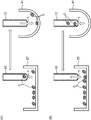
- FIGS. 10A to 10C are diagrams showing Example 4 of cell handling.
- Example 4 shows a specific example of cell addition in the operation 3 (step S10).
- FIG. 10A it is assumed that two cells C1 and C2 are accommodated in the first well 41-1 (compartment).
- the cell C is not accommodated in the second well 41-2 (other section) different from the first well 41-1. That is, the second well 41-2 is a well to which the cell C is added.
- the cells C1 and C2 are determined to be necessary cells that satisfy the determination criterion by the determination unit 75.
- the main control unit 77 aligns the tip opening t of the chip 12 with the cell C2 in the first well 41-1, and sucks the cell C2.
- the cells C1 may be sucked.
- the cell C1 is located near the center of the bottom surface of the first well 41-1, and is convenient for subsequent observation, culture, etc.
- the cell C2 located near the edge of the bottom surface is referred to as the cell C1. Picking is desirable.
- the main control unit 77 moves the chip 12 holding the cells C2 from the first well 41-1 to the second well 41-2 by moving the head main body 62. Let Then, the main control unit 77 discharges the cells C2 from the chip 12 to the second well 41-2.
- the cell C2 picked from the first well 41-1 can be moved to the second well 41-2 in which the number of cells C satisfying the determination criterion is insufficient. Therefore, the number of cells C required for one well 41 can be efficiently aligned.
- FIG. 11 is a diagram showing Example 5 of cell handling.
- the cell C picked from the well 41 is moved to another section divided according to the property of the cell C.
- a cell CA having the first property is accommodated in the first well 41-1 (compartment), and a second property different from the first property is provided in another second well 41-2 (compartment).
- cells CB are housed.
- the cells CA and CB are, for example, cells having different cell types, different sizes, different growth states, and the like. Of course, the cells CA and CB may be mixed and contained in the first and second wells 41-1 and 41-2.
- Example 5 the 1st collection container 43 (other division) and the 2nd collection container 44 (other division) divided according to the nature of cell C are prepared.
- the first collection container 43 is a container for collecting cells CA
- the second collection container 44 is a container for collecting cells CB.
- the main control unit 77 When the main controller 77 collects the necessary cells or cells CA composed of unnecessary cells, the main control unit 77 causes the tip opening t of the first chip 12-1 to access the first well 41-1, and sucks the cells CA. Subsequently, the main controller 77 moves the head main body 62 to move the first chip 12-1 holding the cells CA from the first well 41-1 to the first recovery container 43, and discharges the cells CA. . Similarly, when the main control unit 77 collects the necessary cells or cells CB made of unnecessary cells, the main control unit 77 causes the tip opening t of the second chip 12-2 to access the second well 41-1, and sucks the cells CB. Let Subsequently, the main control unit 77 moves the second main body 12-2 holding the cells CB from the second well 41-2 to the second collection container 44 by moving the head body 62, and discharges the cells CB. .
- the properties picked from the first and second wells 41-1 and 41-2 in the first and second collection containers 43 and 44 prepared according to the properties of the cell C are different. Cells CA and CB are moved. Therefore, the cells CA and CB having different properties are not mixed and stored, which is advantageous when the cells CA and CB are reused.
- the first and second collection containers 43 and 44 may be prepared separately from the microplate 4, but each of the other wells 41 provided in the microplate 4 is the first one. The first and second collection containers 43 and 44 may be used instead.
- Example 6> 12A and 12B are diagrams showing Example 6 of cell handling.
- an example is shown in which the cell C that has been moved from the movement source container to the well 41 that is the movement destination container and picked from the well 41 is returned to the movement source container.
- the cell holder 23 which is a container from which the cells C are moved is shown.
- the cell holder 23 may be a petri dish or a tube for storing the cells C together with the medium, or the dish 2 (sorting container 11) described above.
- the cells C are aspirated from the cell holder 23 by the chip 12, the chip 12 holding the cells C is moved to the well 41, and then the cells C are discharged to the well 41.
- a moving device for moving cells from the cell holder 23 to the well 41 may be a moving device prepared separately from the head unit 6, or the head unit 6 (head device) is also used. There may be.
- the main control unit 77 causes the cell C to be picked from the well 41 according to the state determination result of the cell C. For example, when it is determined that the cell C does not satisfy the determination criterion, the main control unit 77 performs an operation of returning the cell C to the cell holder 23. That is, as shown in FIG. 12B, the main control unit 77 sucks the cells C from the wells 41 with the chip 12 and moves the chip 12 holding the cells C to the cell holder 23. Then, the cells C are discharged from the chip 12 to the cell holder 23.
- the cells C that have been once moved from the cell holder 23 to the well 41 but are determined not to satisfy the determination criteria in the well 41 are returned to the cell holder 23. Accordingly, it is not necessary to separately prepare a storage place or a disposal place for the cells C that do not satisfy the above-described determination criteria.
- FIGS. 13A and 13B are diagrams showing Example 7 of cell handling.
- Example 7 shows an example in which the cells C that have been moved from the dish 2 to the well 41 and picked from the well 41 are returned to the dish 2.
- the cells C are held in the holding recesses 3 of the dish 2 from which the cells C move.
- Some holding recesses 3 are empty holding recesses that do not hold cells C.
- the second holding recess 3-2 adjacent to the first holding recess 3-1 is the empty holding recess.
- the main control unit 77 does not return both of the cells C1 and C2 to the first holding recess 3-1, which originally held the cells, but instead uses the empty second holding The recess 3-2 is used. That is, the cell C1 is returned to the first holding recess 3-1, and the cell C2 is returned to the second holding recess 3-2.
- Example 7 the cells C that were once moved from the dish 2 to the well 41 and then returned to the dish 2 are held again in a state of being arranged in the holding recess 3. That is, the cells C1 and C2 can be held in the first and second holding recesses 3-1 and 3-2, respectively. Therefore, when the cell C moves from the dish 2 thereafter, the head unit 6 can easily perform the moving operation efficiently.
- FIGS. 14A to 15C are diagrams showing Example 8 of cell handling.
- Example 8 shows an example of the reset operation of the well 41 using the large chip 12C.
- “reset” is to remove all the cells C from the well 41 to which the cells C have been moved once, and to enable the acceptance of new cells C.
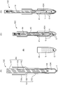
- FIG. 14A is a cross-sectional view showing the structure of the large chip 12C.
- the large chip 12 ⁇ / b> C includes a syringe 13 that includes a tubular passage 13 ⁇ / b> H serving as a suction path for the cells C and a plunger 14 that moves forward and backward in the tubular passage 13 ⁇ / b> H while being in sliding contact with the inner peripheral wall of the syringe 13.
- the syringe 13 includes a syringe base end portion 131 made of a large-diameter cylindrical body, a syringe main body portion 132 made of a thin and long cylindrical body, and a tapered tube portion 133 connecting the base end portion 131 and the main body portion 132. including.
- the tubular passage 13H is formed in the syringe main body 132.
- the tip opening t described above is provided at the tip of the syringe body 132.
- the plunger 14 includes a plunger base end portion 141 formed of a cylindrical body, a columnar plunger main body portion 142, and a taper portion 143 that connects the base end portion 141 and the main body portion 142. In a state where the plunger 14 is inserted into the syringe 13 most deeply, the distal end portion 144 of the plunger 14 slightly projects from the distal end opening t.
- the plunger 14 is assembled to the syringe 13 so that the plunger main body 142 slides in the vertical direction within the tubular passage 13H of the syringe main body 132.
- a suction force is generated at the tip opening t.
- a discharge force is generated at the tip opening t.
- the main control unit 77 executes the reset operation of the well 41 as shown in FIGS. 14C to 15C using the large chip 12C described above (the whole cell removal in the above operation 1). ).
- the tubular passage 13H of the large chip 12C has a volume capable of sucking all the medium L filled in the well 41.
- the main control unit 77 moves the plunger 14 up and down by a predetermined stroke. As a result, suction force and discharge force are alternately generated at the tip opening t, and the cells C that have settled at the bottom of the well 41 are swung upward by the flow of the medium L. By this. The cells C can be easily sucked into the large chip 12C. And as shown in FIG.14 (D), the main control part 77 raises the plunger 14, and attracts
- the main control unit 77 moves the large chip 12C holding the cells C to the disposal location of the cells C.
- FIG. 15A an example in which the disposal place is the sorting container 11 is shown (for ease of illustration, the sorting container 11 is drawn with a considerably reduced size. ).
- the main control unit 77 causes the tip opening t of the large chip 12 ⁇ / b> C to enter the upper opening 11 ⁇ / b> H, and is immersed in the medium L stored in the sorting container 11. Then, the plunger 14 is lowered, and the cells C held in the tubular passage 13H are discharged together with the medium L to the sorting container 11. The discharged cells C are held on the dish 2.
- the main control unit 77 raises the plunger 14 while the tip opening t is immersed in the culture medium L as shown in FIG. Thereby, the culture medium L is sucked into the tubular passage 13H of the large chip 12C. Then, the main control unit 77 moves the large chip 12C holding the culture medium L to the position of the well 41 that has been emptied first. Subsequently, as shown in FIG. 15C, the medium L is discharged from the large chip 12 ⁇ / b> C into the well 41. As a result, the well 41 is ready to accept a new cell C.
- FIGS. 16A to 17C are diagrams showing Example 9 of cell handling.
- Example 9 shows an example of the picking operation of the cell C from the well 41 and the additional operation of the cell C to the well 41 using the small chip 12D.
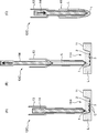
- FIG. 16A is a cross-sectional view showing the structure of the small chip 12D.
- the small chip 12D includes a small-diameter syringe 15 that includes a tubular passage 15H serving as a suction path for the cells C and a plunger 16 that moves forward and backward in the tubular passage 15H while slidingly contacting the inner peripheral wall of the syringe 15.
- the syringe 15 includes a syringe base end portion 151 made of a large-diameter cylindrical body, a syringe main body portion 152 made of a thin and long cylindrical body, and a tapered tube portion 153 connecting the base end portion 151 and the main body portion 152. including.
- the tubular passage 15H is formed in the syringe main body 152.
- the tip opening t described above is provided at the tip of the syringe body 152.
- the plunger 16 includes a plunger base end portion 161 made of a cylindrical body, a needle-like plunger main body portion 162, and a taper portion 163 that connects the base end portion 161 and the main body portion 162. In a state where the plunger 16 is inserted most deeply into the syringe 15, the distal end portion 164 of the plunger 16 slightly projects from the distal end opening t.
- the plunger 16 is assembled to the syringe 15 so that the plunger main body 162 slides up and down in the tubular passage 15H of the syringe main body 152.
- a suction force is generated at the tip opening t.
- a discharge force is generated at the tip opening t.
- the main control unit 77 performs the picking and adding operation of the cell C as shown in FIGS. 16C to 17C using the small chip 12D described above (all the operations 1 described above). Cell removal or partial cell removal in action 2).
- the volume of the tubular passage 15H of the small chip 12D is a volume capable of sucking only a part of the medium L filled in the well 41.
- the main control unit 77 causes the small chip 12D to enter the well 41 and causes the tip opening t to approach the cell C in the medium L. Then, the plunger 16 is raised to suck the cells C together with the surrounding medium L into the tubular passage 15H. By this suction, the well 41 is in a state where the cells C are not present and only the medium L is present, or only the necessary cells C remain together with the medium L.
- the main control unit 77 moves the small chip 12D holding the cells C to the sorting container 11 which is a disposal place of the cells C. Subsequently, the main control unit 77 causes the tip opening t of the small chip 12D to enter the upper opening 11H, and is immersed in the culture medium L stored in the sorting container 11. At this time, the position may be aligned with a specific holding recess 3. Then, the plunger 16 is lowered, and the cells C held in the tubular passage 15H are discharged together with the culture medium L to the sorting container 11. The discharged cells C are held on the dish 2.
- the main control unit 77 holds the tip opening t of the small chip 12D in the cell CT that is carried in a place different from the discard area of the dish 2 and that satisfies the above-mentioned determination criteria. To align. Then, the plunger 16 is raised, and the cell CT is sucked together with the medium L. Thereafter, the main control unit 77 moves the small chip 12D holding the cells C to the position of the well 41 where the cells C were picked first. Subsequently, as shown in FIG. 17C, the cells CT are discharged together with the medium L from the small chip 12D to the well 41. Thereby, the cell CT can be added to the well 41.
- the camera unit 5 is exemplified as an example of the cell detection unit accommodated in the well 41. That is, the example which detected the cell C based on the image was shown.
- the cell detection unit may be a physical quantity sensor such as an optical or acoustic sensor.
- the cell C may be recognized by irradiating the cell C with light and observing the fluorescence.
- a sonar equipped with a sound source may be used and the cell C may be recognized based on the reverberant sound.
- the microplate 4 having the wells 41 is exemplified as the container having the compartment that can accommodate the cells.
- the container may be the dish 2, and the section may be the holding recess 3, and the cell C may be picked or released from the holding recess 3 and the cell C may be added.
- the head unit 6 including the chip 12 is illustrated as an example of the head device, and the suction of the cell C to the chip 12 as the picking mode and the suction of the cell C as the release mode The discharge from the chip 12 was illustrated.
- the head device may be any device that can hold one or a plurality of cells C and release the held cells C by mechanical, electrical, or magnetic force.
- a cell handling device includes a container having a compartment that can accommodate cells, a cell detection unit that detects cells contained in the compartment, picking of cells, and movement and release of the picked cells.
- a cell state including at least one of the number, properties, and arrangement of cells contained in the compartment based on a detection result of the head device to be performed, a control unit for controlling the operation of the head device, and a detection result of the cell detection unit
- this cell handling device based on the result of the cell state determination, for example, when cells having an inappropriate state are accommodated in the compartment, all or a part of the cells are picked, the cells are insufficient In this case, either an operation for adding a new cell to the compartment or an operation for finishing the processing for the compartment containing the cell as intended is selected. Therefore, the container in which the cells are once accommodated in the compartment can be corrected to the state in which the cells are accommodated as intended by the cell handling device.
- the determination by the determination unit is to determine whether the determination target cell satisfies a predetermined determination criterion regarding the property, and the control unit is configured to determine the determination. It is desirable to cause the head device to perform an operation of picking all the cells determined not to meet the criteria from the compartment.
- this cell handling device According to this cell handling device, cells that do not satisfy the determination criteria are removed from the compartment, so to speak, the compartment can be reset. Therefore, it is possible to correct the cell to be accommodated as intended by, for example, re-injecting the cell satisfying the determination criterion into the section.
- the control when the determination unit determines in the state determination that there are a plurality of cells in the partition and the cells are arranged at a predetermined distance, the control Preferably, the unit causes the head device to perform an operation of picking some of the plurality of cells.
- the container has another compartment separately from the compartment, and the control unit moves the cell picked from the compartment to the other compartment and releases the operation. It is desirable to have the head device execute.
- cells picked from the compartment can be moved, for example, to another compartment where the number of good cells is insufficient. Therefore, the number of cells required for one compartment can be efficiently arranged.
- the cell handling device further includes another compartment that is classified according to the nature of the cell, and the control unit moves the cell picked from the compartment to the other compartment. It is desirable to cause the head device to perform an operation of releasing and releasing.
- the picked cells are moved to other compartments classified according to the properties of the cells. Therefore, cells having different properties are not mixed and stored, which is advantageous when reusing these cells.
- the other compartment may be another compartment provided in the container or another container.
- the cell handling device further includes a cell holder that holds cells accommodated in the compartment of the container, and a moving device that moves cells from the cell holder to the compartment of the container, and the determination unit includes It is desirable to perform the state determination on the cells moved from the cell holder to the compartment.
- the state of the cells moved from the cell holder to the compartment of the container is determined by the moving device. That is, the cell holder is a cell movement source and the container is a cell movement destination, and the cell state is determined at the movement destination. Therefore, the cell handling device of the present invention can be applied to a general cell transfer device to form a state in which cells are accommodated as intended in the compartment of the transfer destination container.
- the determination unit performs a state determination for determining whether or not a predetermined determination criterion regarding the property is satisfied for the cells moved from the cell holder to the compartment,
- the control unit causes the head device to perform an operation of picking the cell from the compartment and returning the cell to the cell holder in accordance with the result of the state determination.
- this cell handling apparatus for example, cells that have been once moved to the compartment but are determined not to satisfy the determination criteria are returned to the cell holder. Therefore, a storage place or a disposal place for cells that do not satisfy the determination criteria is not required.
- the cell holder includes a plurality of holding units that independently hold one or a plurality of cells, and the control unit performs the operation of returning the picked cells to the cell holder. It is desirable to cause the head device to perform an operation of returning the cells to an empty holding unit among the holding units.
- the cells that are once moved from the cell holder to the compartment and then returned to the cell holder are again held in a state of being arranged in the holding portion of the cell holder. Accordingly, when the cells are moved from the cell holder thereafter, the moving device can easily perform the moving operation efficiently.
- the head device also serves as the moving device. Thereby, the structure of a cell handling apparatus can be simplified.
- the cells are dispersed in the liquid in the compartment, and the head device includes a tip having a tip opening capable of sucking the cells and discharging the sucked cells,
- the cells are sucked together with the surrounding liquid during the picking, and the cells are discharged together with the sucked liquid during the release.
- this cell handling apparatus it is possible to execute picking and releasing of cells by sucking and discharging the chip, and it is possible to simplify and facilitate these operations.
- the control unit sucks the plurality of cells into the chip when the distance between the plurality of cells is shorter than a predetermined distance.
- the head device can be caused to perform an operation of sucking each of the plurality of cells by the individual suction operation to the chip. desirable.
- the chip can be caused to perform a suction operation according to the arrangement mode of the cells in the compartment. That is, when a plurality of cells are arranged close to the compartment, it is difficult to suck these cells individually with the chip. In this case, the plurality of cells are sucked into the chip by one suction operation. On the other hand, when a plurality of cells are spaced apart from each other in the compartment, these cells can be individually aspirated with the chip. Therefore, in this case, each of the cells is sucked into the chip by a separate suction operation.
- the head device in addition to the head device, the head device further includes another head device, and the control unit picks up a plurality of cells from the section, and the head device or the other head device. It is desirable to select whether the plurality of cells are picked or whether the plurality of cells are picked by the head device and the other head device.
- the picking pattern of cells can be diversified by utilizing the head device and the other head device.
- the cell detection unit includes an imaging device that acquires an image of a cell accommodated in the compartment.
- this cell handling device for example, image processing is performed on an image acquired by the imaging device, so that cells contained in the compartment can be detected easily and reliably.
- a cell handling device capable of bringing cells into a container as intended in a container having a compartment for containing cells.
Landscapes
- Health & Medical Sciences (AREA)
- Chemical & Material Sciences (AREA)
- Engineering & Computer Science (AREA)
- Life Sciences & Earth Sciences (AREA)
- Bioinformatics & Cheminformatics (AREA)
- Organic Chemistry (AREA)
- Zoology (AREA)
- Wood Science & Technology (AREA)
- General Health & Medical Sciences (AREA)
- Clinical Laboratory Science (AREA)
- Biochemistry (AREA)
- Genetics & Genomics (AREA)
- Biomedical Technology (AREA)
- Biotechnology (AREA)
- Microbiology (AREA)
- Sustainable Development (AREA)
- General Engineering & Computer Science (AREA)
- Analytical Chemistry (AREA)
- Chemical Kinetics & Catalysis (AREA)
- Molecular Biology (AREA)
- Hematology (AREA)
- Human Computer Interaction (AREA)
- Computer Hardware Design (AREA)
- Apparatus Associated With Microorganisms And Enzymes (AREA)
Priority Applications (4)
| Application Number | Priority Date | Filing Date | Title |
|---|---|---|---|
| US16/603,050 US11572537B2 (en) | 2017-04-20 | 2018-02-26 | Cell handling device |
| EP18788636.1A EP3604496A4 (de) | 2017-04-20 | 2018-02-26 | Vorrichtung zur handhabung von zellen |
| JP2019513249A JP6883648B2 (ja) | 2017-04-20 | 2018-02-26 | 細胞ハンドリング装置 |
| CN201880025175.4A CN110520518A (zh) | 2017-04-20 | 2018-02-26 | 细胞处理装置 |
Applications Claiming Priority (2)
| Application Number | Priority Date | Filing Date | Title |
|---|---|---|---|
| JP2017-083908 | 2017-04-20 | ||
| JP2017083908 | 2017-04-20 |
Publications (1)
| Publication Number | Publication Date |
|---|---|
| WO2018193718A1 true WO2018193718A1 (ja) | 2018-10-25 |
Family
ID=63856267
Family Applications (1)
| Application Number | Title | Priority Date | Filing Date |
|---|---|---|---|
| PCT/JP2018/006966 WO2018193718A1 (ja) | 2017-04-20 | 2018-02-26 | 細胞ハンドリング装置 |
Country Status (5)
| Country | Link |
|---|---|
| US (1) | US11572537B2 (de) |
| EP (1) | EP3604496A4 (de) |
| JP (1) | JP6883648B2 (de) |
| CN (1) | CN110520518A (de) |
| WO (1) | WO2018193718A1 (de) |
Cited By (4)
| Publication number | Priority date | Publication date | Assignee | Title |
|---|---|---|---|---|
| WO2019146291A1 (ja) * | 2018-01-29 | 2019-08-01 | ヤマハ発動機株式会社 | 生体対象物処理装置 |
| CN110124763A (zh) * | 2019-05-15 | 2019-08-16 | 林伟阳 | 一种干细胞溶液全自动分装方法 |
| WO2023233464A1 (ja) * | 2022-05-30 | 2023-12-07 | ヤマハ発動機株式会社 | 細胞移動装置 |
| JP7460053B2 (ja) | 2020-06-12 | 2024-04-02 | 株式会社ピーエムティー | 操作装置及び操作方法 |
Families Citing this family (1)
| Publication number | Priority date | Publication date | Assignee | Title |
|---|---|---|---|---|
| JP2022084356A (ja) * | 2020-11-26 | 2022-06-07 | 株式会社島津製作所 | 細胞ピッキング装置および細胞ピッキング方法 |
Citations (6)
| Publication number | Priority date | Publication date | Assignee | Title |
|---|---|---|---|---|
| JP2006333710A (ja) * | 2005-05-31 | 2006-12-14 | Nikon Corp | 細胞の自動良否判定システム |
| JP2014036618A (ja) * | 2012-08-16 | 2014-02-27 | Sysmex Corp | 癌化情報取得装置、細胞分析装置、および細胞採取適否判定装置、ならびに、癌化情報取得方法および細胞採取適否判定方法。 |
| JP2014100109A (ja) * | 2012-11-21 | 2014-06-05 | Nikon Corp | 細胞ピッキング支援装置及び表示装置 |
| WO2015087371A1 (ja) | 2013-12-12 | 2015-06-18 | ヤマハ発動機株式会社 | 対象物の移動装置 |
| WO2016020992A1 (ja) * | 2014-08-05 | 2016-02-11 | ヤマハ発動機株式会社 | 培養装置、これを用いた培養方法及び細胞凝集塊の選別方法 |
| WO2017017990A1 (ja) * | 2015-07-28 | 2017-02-02 | ヤマハ発動機株式会社 | 対象物移動方法及び装置 |
Family Cites Families (8)
| Publication number | Priority date | Publication date | Assignee | Title |
|---|---|---|---|---|
| US4554839A (en) * | 1983-10-14 | 1985-11-26 | Cetus Corporation | Multiple trough vessel for automated liquid handling apparatus |
| CN101048492B (zh) * | 2004-11-09 | 2013-01-09 | 株式会社钟化 | 细胞培养装置、图像处理装置和细胞检测系统 |
| CN101072881B (zh) * | 2004-12-08 | 2010-09-08 | 国立大学法人大阪大学 | 细胞的评价方法和细胞测定用系统 |
| EP2064310B1 (de) * | 2006-09-22 | 2017-04-26 | ALS Automated Lab Solutions GmbH | Verfahren und vorrichtung zur automatisierten entnahme von zellen und/oder zellkolonien |
| US8691149B2 (en) * | 2007-11-06 | 2014-04-08 | Abbott Laboratories | System for automatically loading immunoassay analyzer |
| JP5896104B2 (ja) | 2011-06-24 | 2016-03-30 | 国立大学法人佐賀大学 | 細胞の立体構造体製造装置 |
| CN110042060A (zh) | 2014-08-05 | 2019-07-23 | 雅马哈发动机株式会社 | 板 |
| US10184104B2 (en) * | 2015-11-19 | 2019-01-22 | Alexander Lee Lianides | Automated system for cultivating transgenic C. elegans |
-
2018
- 2018-02-26 EP EP18788636.1A patent/EP3604496A4/de not_active Withdrawn
- 2018-02-26 WO PCT/JP2018/006966 patent/WO2018193718A1/ja unknown
- 2018-02-26 CN CN201880025175.4A patent/CN110520518A/zh active Pending
- 2018-02-26 US US16/603,050 patent/US11572537B2/en active Active
- 2018-02-26 JP JP2019513249A patent/JP6883648B2/ja active Active
Patent Citations (6)
| Publication number | Priority date | Publication date | Assignee | Title |
|---|---|---|---|---|
| JP2006333710A (ja) * | 2005-05-31 | 2006-12-14 | Nikon Corp | 細胞の自動良否判定システム |
| JP2014036618A (ja) * | 2012-08-16 | 2014-02-27 | Sysmex Corp | 癌化情報取得装置、細胞分析装置、および細胞採取適否判定装置、ならびに、癌化情報取得方法および細胞採取適否判定方法。 |
| JP2014100109A (ja) * | 2012-11-21 | 2014-06-05 | Nikon Corp | 細胞ピッキング支援装置及び表示装置 |
| WO2015087371A1 (ja) | 2013-12-12 | 2015-06-18 | ヤマハ発動機株式会社 | 対象物の移動装置 |
| WO2016020992A1 (ja) * | 2014-08-05 | 2016-02-11 | ヤマハ発動機株式会社 | 培養装置、これを用いた培養方法及び細胞凝集塊の選別方法 |
| WO2017017990A1 (ja) * | 2015-07-28 | 2017-02-02 | ヤマハ発動機株式会社 | 対象物移動方法及び装置 |
Non-Patent Citations (1)
| Title |
|---|
| See also references of EP3604496A4 |
Cited By (6)
| Publication number | Priority date | Publication date | Assignee | Title |
|---|---|---|---|---|
| WO2019146291A1 (ja) * | 2018-01-29 | 2019-08-01 | ヤマハ発動機株式会社 | 生体対象物処理装置 |
| JPWO2019146291A1 (ja) * | 2018-01-29 | 2021-01-07 | ヤマハ発動機株式会社 | 生体対象物処理装置 |
| CN110124763A (zh) * | 2019-05-15 | 2019-08-16 | 林伟阳 | 一种干细胞溶液全自动分装方法 |
| CN110124763B (zh) * | 2019-05-15 | 2021-07-02 | 哈尔滨工大国际干细胞工程研究院有限公司 | 一种干细胞溶液全自动分装方法 |
| JP7460053B2 (ja) | 2020-06-12 | 2024-04-02 | 株式会社ピーエムティー | 操作装置及び操作方法 |
| WO2023233464A1 (ja) * | 2022-05-30 | 2023-12-07 | ヤマハ発動機株式会社 | 細胞移動装置 |
Also Published As
| Publication number | Publication date |
|---|---|
| US20200048598A1 (en) | 2020-02-13 |
| CN110520518A (zh) | 2019-11-29 |
| US11572537B2 (en) | 2023-02-07 |
| JPWO2018193718A1 (ja) | 2020-02-06 |
| EP3604496A4 (de) | 2020-04-01 |
| JP6883648B2 (ja) | 2021-06-09 |
| EP3604496A1 (de) | 2020-02-05 |
Similar Documents
| Publication | Publication Date | Title |
|---|---|---|
| WO2018193718A1 (ja) | 細胞ハンドリング装置 | |
| WO2017110005A1 (ja) | 対象物のピックアップ方法 | |
| JP6793244B2 (ja) | 撮像システム | |
| JP6450476B2 (ja) | 対象物移動方法及び装置 | |
| JP6853880B2 (ja) | 細胞移動方法及び細胞移動装置 | |
| WO2018074086A1 (ja) | 細胞移動装置 | |
| WO2019150756A1 (ja) | 生体対象物の移動方法及び移動装置 | |
| JP7018078B2 (ja) | 撮像システム | |
| JP6710772B2 (ja) | 細胞移動装置及び細胞移動方法 | |
| JP6947905B2 (ja) | 撮像システム及び生体対象物移動装置 | |
| JP6913184B2 (ja) | 生体対象物処理装置 | |
| WO2023233464A1 (ja) | 細胞移動装置 | |
| WO2018070153A1 (ja) | 細胞の撮像方法 |
Legal Events
| Date | Code | Title | Description |
|---|---|---|---|
| 121 | Ep: the epo has been informed by wipo that ep was designated in this application |
Ref document number: 18788636 Country of ref document: EP Kind code of ref document: A1 |
|
| ENP | Entry into the national phase |
Ref document number: 2019513249 Country of ref document: JP Kind code of ref document: A |
|
| NENP | Non-entry into the national phase |
Ref country code: DE |
|
| ENP | Entry into the national phase |
Ref document number: 2018788636 Country of ref document: EP Effective date: 20191031 |