WO2018190627A1 - 액체 렌즈 제어 회로 - Google Patents
액체 렌즈 제어 회로 Download PDFInfo
- Publication number
- WO2018190627A1 WO2018190627A1 PCT/KR2018/004222 KR2018004222W WO2018190627A1 WO 2018190627 A1 WO2018190627 A1 WO 2018190627A1 KR 2018004222 W KR2018004222 W KR 2018004222W WO 2018190627 A1 WO2018190627 A1 WO 2018190627A1
- Authority
- WO
- WIPO (PCT)
- Prior art keywords
- voltage
- liquid lens
- period
- amplitude
- driving voltage
- Prior art date
Links
Images


Classifications
-
- G—PHYSICS
- G02—OPTICS
- G02B—OPTICAL ELEMENTS, SYSTEMS OR APPARATUS
- G02B26/00—Optical devices or arrangements for the control of light using movable or deformable optical elements
- G02B26/004—Optical devices or arrangements for the control of light using movable or deformable optical elements based on a displacement or a deformation of a fluid
- G02B26/005—Optical devices or arrangements for the control of light using movable or deformable optical elements based on a displacement or a deformation of a fluid based on electrowetting
-
- G—PHYSICS
- G02—OPTICS
- G02B—OPTICAL ELEMENTS, SYSTEMS OR APPARATUS
- G02B3/00—Simple or compound lenses
- G02B3/12—Fluid-filled or evacuated lenses
- G02B3/14—Fluid-filled or evacuated lenses of variable focal length
-
- G—PHYSICS
- G02—OPTICS
- G02B—OPTICAL ELEMENTS, SYSTEMS OR APPARATUS
- G02B27/00—Optical systems or apparatus not provided for by any of the groups G02B1/00 - G02B26/00, G02B30/00
- G02B27/64—Imaging systems using optical elements for stabilisation of the lateral and angular position of the image
-
- G—PHYSICS
- G03—PHOTOGRAPHY; CINEMATOGRAPHY; ANALOGOUS TECHNIQUES USING WAVES OTHER THAN OPTICAL WAVES; ELECTROGRAPHY; HOLOGRAPHY
- G03B—APPARATUS OR ARRANGEMENTS FOR TAKING PHOTOGRAPHS OR FOR PROJECTING OR VIEWING THEM; APPARATUS OR ARRANGEMENTS EMPLOYING ANALOGOUS TECHNIQUES USING WAVES OTHER THAN OPTICAL WAVES; ACCESSORIES THEREFOR
- G03B13/00—Viewfinders; Focusing aids for cameras; Means for focusing for cameras; Autofocus systems for cameras
- G03B13/32—Means for focusing
-
- H—ELECTRICITY
- H04—ELECTRIC COMMUNICATION TECHNIQUE
- H04N—PICTORIAL COMMUNICATION, e.g. TELEVISION
- H04N23/00—Cameras or camera modules comprising electronic image sensors; Control thereof
- H04N23/60—Control of cameras or camera modules
-
- H—ELECTRICITY
- H04—ELECTRIC COMMUNICATION TECHNIQUE
- H04N—PICTORIAL COMMUNICATION, e.g. TELEVISION
- H04N23/00—Cameras or camera modules comprising electronic image sensors; Control thereof
- H04N23/60—Control of cameras or camera modules
- H04N23/68—Control of cameras or camera modules for stable pick-up of the scene, e.g. compensating for camera body vibrations
-
- G—PHYSICS
- G03—PHOTOGRAPHY; CINEMATOGRAPHY; ANALOGOUS TECHNIQUES USING WAVES OTHER THAN OPTICAL WAVES; ELECTROGRAPHY; HOLOGRAPHY
- G03B—APPARATUS OR ARRANGEMENTS FOR TAKING PHOTOGRAPHS OR FOR PROJECTING OR VIEWING THEM; APPARATUS OR ARRANGEMENTS EMPLOYING ANALOGOUS TECHNIQUES USING WAVES OTHER THAN OPTICAL WAVES; ACCESSORIES THEREFOR
- G03B13/00—Viewfinders; Focusing aids for cameras; Means for focusing for cameras; Autofocus systems for cameras
- G03B13/32—Means for focusing
- G03B13/34—Power focusing
- G03B13/36—Autofocus systems
-
- G—PHYSICS
- G03—PHOTOGRAPHY; CINEMATOGRAPHY; ANALOGOUS TECHNIQUES USING WAVES OTHER THAN OPTICAL WAVES; ELECTROGRAPHY; HOLOGRAPHY
- G03B—APPARATUS OR ARRANGEMENTS FOR TAKING PHOTOGRAPHS OR FOR PROJECTING OR VIEWING THEM; APPARATUS OR ARRANGEMENTS EMPLOYING ANALOGOUS TECHNIQUES USING WAVES OTHER THAN OPTICAL WAVES; ACCESSORIES THEREFOR
- G03B17/00—Details of cameras or camera bodies; Accessories therefor
- G03B17/02—Bodies
- G03B17/12—Bodies with means for supporting objectives, supplementary lenses, filters, masks, or turrets
Definitions
- Embodiments relate to a liquid lens and a camera module and optical device including the same. More specifically, the embodiment relates to a camera module and an optical device including a liquid lens control module or a liquid lens control device or a liquid lens control circuit for controlling a liquid lens that can adjust a focal length using electrical energy.
- the user of a portable device wants an optical device having a high resolution, small size, and various shooting functions.
- various shooting functions include an auto focusing function, an image stabilization function, or an optical image stabilizer (OIS) function.
- the above-described shooting function may be implemented by directly moving a lens by combining several lenses, but when the number of lenses is increased, the size of the optical device may be increased.
- the AF function and the OIS function are performed by moving or tilting several lens modules fixed to the lens holder and aligned with the optical axis in a direction perpendicular to the optical axis or the optical axis, and driving a separate lens to drive the lens module.
- the device is used.
- the lens driving apparatus has high power consumption, and the overall thickness becomes thick. Therefore, research has been conducted on liquid lenses that perform AF and OIS functions by electrically adjusting the curvature of two liquid interfaces.
- the embodiment stabilizes the movement of an interface in a liquid lens by sequentially or gradually supplying a voltage for driving the liquid lens to a plurality of individual electrodes in a camera module including a liquid lens that can adjust a focal length using electrical energy. It is possible to provide an apparatus and a method which can be used.
- the embodiment can reduce the time required to stabilize the interface due to the free and flexible movement of the interface in the process of controlling the interface in the liquid lens by sequentially applying electrical energy to a plurality of individual electrodes of the liquid lens, The operation time according to the focus shift of the camera module or the optical device including the lens can be reduced.
- the embodiment by controlling the voltage pulse for driving the liquid lens in the camera module including a liquid lens that can adjust the focal length by using electrical energy to supply a plurality of individual electrodes to the movement of the interface in the liquid lens It is possible to provide an apparatus and a method capable of stabilizing.
- the embodiment may increase the operation speed of the liquid lens by adjusting the pulse period of the driving voltage according to the state of the liquid lens (eg, whether or not diopter changes) in order to control the driving voltage of the pulse type applied to the liquid lens.
- the present invention can provide a device and a method.
- the embodiment can provide a device and method that can reduce the load on the switching circuit by adjusting the pulse period of the driving voltage while controlling the liquid lens to reduce the power consumption of the control circuit of the liquid lens.
- a liquid lens control circuit may include a liquid lens including a common electrode and a plurality of individual electrodes; A voltage generator configured to supply a voltage to the plurality of individual electrodes and the common electrode in the liquid lens; And a controller configured to control timing to sequentially supply the voltage to each of the plurality of individual electrodes.
- the plurality of individual electrodes may include a first individual electrode, a second individual electrode, a third individual electrode, and a fourth individual electrode
- the control unit may apply the voltage to the first individual electrode and then the second individual electrode.
- the voltage is applied to an electrode, the voltage is applied to the second individual electrode, and the voltage is applied to the third individual electrode, and the voltage is applied to the third individual electrode.
- the voltage can be applied.
- the first individual electrode and the second individual electrode may be disposed at positions symmetrical with respect to the center of the liquid lens.
- the controller may sequentially apply the voltage to each of the plurality of individual electrodes at predetermined time intervals.
- the timing may be an integer multiple of the period of the voltage.
- the controller may apply the voltages applied from the first individual electrodes to the fourth individual electrodes in the order of high voltage to low voltage.
- a liquid lens control circuit may include a liquid lens including a common electrode and a plurality of individual electrodes; A voltage generator configured to generate an output voltage by controlling the magnitude of the input voltage; And a voltage period controller configured to control a period of a voltage supplied to the common electrode and the plurality of individual electrodes using the output voltage of the voltage generator.
- the voltage period may include a section that is changed from a preset first period to a second period shorter than the first period.
- the method may include a section that changes to the first period after the section that changes to the second period.
- the amplitude of the voltage in the section having the voltage period of the second period may include different first amplitude and second amplitude.
- the amplitude of the section changed to the first period after the section changed to the second period may be between the first amplitude and the second amplitude.
- the amplitude of the voltage applied to any one of the plurality of individual electrodes and the amplitude of the voltage applied to the common electrode may correspond to each other.
- a liquid lens control circuit may include a liquid lens including a common electrode and a plurality of individual electrodes; A voltage generator configured to generate a driving voltage for driving the liquid lens; And when the amplitude of the driving voltage applied between the common electrode and one of the plurality of individual electrodes is changed from the first amplitude to the second amplitude, the driving voltage is a first section in which the amplitude of the driving voltage increases. And a second section in which the amplitude decreases, wherein the second amplitude is between the maximum amplitude of the first section and the minimum amplitude of the second section.
- the voltage period of the first period and the second period may be smaller than the period of the driving voltage applied to the first amplitude and the second amplitude.
- the maximum amplitude of the first section may be 130% or more of the second amplitude, and the minimum amplitude of the second section may be 85% or less of the second amplitude.
- a liquid lens control circuit may include a liquid lens including a common electrode and a plurality of individual electrodes; A voltage generator configured to generate a driving voltage for driving the liquid lens; And a first period in which the duty ratio of the driving voltage is changed when the Vrms value of the driving voltage applied between the common electrode and one of the plurality of individual electrodes is changed from the first V rms value to the second Vrms value. And a second period having a duty ratio different from the first period, wherein at least one of the first period or the second period has a duty ratio greater than that in the period having the second Vrms value. have.
- the duty ratio of the section having the second Vrms value may be smaller than the duty ratio of the first section.
- the duty ratio of the section having the second Vrms value may be greater than the duty ratio of the section having the first Vrms value.
- the duty ratio of the section having the second Vrms value may be greater than the duty ratio of the first section.
- the duty ratio of the section having the second Vrms value may be smaller than the duty ratio of the section having the first Vrms value.
- the height and the period of the pulse of the driving voltage may be constant.
- the first section has a third Vrms value
- the second section has a fourth Vrms value
- the formula of (third Vrms value> second Vrms value> fourth Vrms value> first Vrms value) Can be satisfied.
- the first section has a third Vrms value
- the second section has a fourth Vrms value
- the formula of (first Vrms value> fourth Vrms value> second Vrms value> third Vrms value) Can be satisfied.
- the driving voltage period may include a period of changing from a preset first period to a second period shorter than the first period.
- the third Vrms value may be within 130% of the second Vrms value, and the fourth Vrms value may be within 85% of the second Vrms value.
- the width or period of the pulse of the driving voltage may vary.
- the driving voltage of the liquid lens capable of adjusting the focal length may be sequentially applied to reduce side effects due to rapid focal shift of the liquid lens.
- the embodiment may be a more stable and agile movement of the interface according to the control of the liquid lens can be mounted on the liquid lens, such as a camera module or an optical device with a large movement.
- the embodiment controls the pulse period of the driving voltage and the amplitude of the pulse of the liquid lens which can adjust the focal length and apply it to a plurality of individual electrodes, thereby allowing the movement of the interface according to the rapid focus movement of the liquid lens. It can be obtained quickly and reliably.
- the embodiment controls the duty ratio of the pulse pulse of the driving voltage of the liquid lens that can adjust the focal length to apply an excess voltage and an undervoltage to the plurality of individual electrodes when the driving voltage changes, so that the rapid focal shift of the liquid lens Faster and more stable movement of the interface can be obtained.
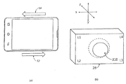
- 1 is a diagram illustrating an example of a camera module.
- FIG. 2 shows an exemplary cross-sectional view of a lens assembly included in a camera module.
- 3 (a) and 3 (b) show a perspective view and an equivalent circuit of a liquid lens whose focal length is adjusted in correspondence with a driving voltage, respectively.
- FIG. 4 shows an exemplary cross-sectional view of a liquid lens.
- 5 (a) and 5 (b) are diagrams for explaining a lens correction method of a liquid lens.
- 7 (a) and 7 (b) are diagrams for explaining the movement of the interface in the liquid lens.
- FIG. 8 is a block diagram of a liquid lens control circuit according to the first embodiment.
- 9 (a) and 9 (b) show waveform diagrams for explaining the driving voltage applied to the liquid lens by the liquid lens control circuit according to the first embodiment.
- 10 (a) and 10 (b) are views for explaining a process in which a driving voltage is applied to a liquid lens in response to a movement of a portable device equipped with a liquid lens.
- FIG. 11 is a view for explaining a method of controlling a liquid lens through supplying an excess voltage.
- FIG. 12 is a block diagram of a liquid lens control circuit according to the second embodiment.
- FIG. 13 is a waveform diagram illustrating a method of driving a liquid lens according to a second embodiment.
- 15 (a) and 15 (b) are waveform diagrams for explaining the second control method of the liquid lens through the excess voltage supply according to the second embodiment.
- 16 is a block diagram of a liquid lens control circuit according to a third embodiment.
- 17A and 17B are waveform diagrams for describing a method of driving a liquid lens according to a third embodiment.
- 18A and 18B are waveform diagrams for explaining a method of controlling a driving voltage of a liquid lens according to a third embodiment.
- FIG. 1 is a diagram exemplarily illustrating a camera device (or a camera module).
- the camera module may include a lens assembly 22 and an image sensor 26.
- the camera module may further include a control circuit 24.
- the lens assembly 22 may include a liquid lens whose focal length is adjusted in response to the applied voltage.
- the lens assembly 22 may include a plurality of lenses including a first lens (or a liquid lens) whose focal length is adjusted in response to a driving voltage applied between the common terminal and the plurality of individual terminals.
- the control circuit 24 may supply a driving voltage to the first lens.
- the image sensor 26 is aligned with the lens assembly 22 and can convert light transmitted through the lens assembly 22 into an electrical signal.
- the camera module may include a control circuit 24 formed on one printed circuit board (PCB) and a lens assembly 22 including an image sensor 26 and a plurality of lenses. It is only one example and does not limit the scope of the embodiment.
- the configuration of the control circuit 24 can be designed differently depending on the specifications required for the camera module. In particular, when reducing the magnitude of the voltage applied to the liquid lens, the control circuit 24 may be implemented as a single chip. Through this, the size of the camera module mounted in the portable device can be further reduced.
- FIG 2 shows an exemplary cross-sectional view of the lens assembly 22 included in the camera device (or camera module).
- the lens assembly 22 may include a first lens unit 100, a second lens unit 200, a liquid lens unit 300, a lens holder 400, and a connection unit 500. Can be.
- the connection part 500 electrically connects the image sensor 26 and the liquid lens, and may include a substrate, a wire or an electric wire to be described later.
- the illustrated structure of the lens assembly 22 is only one example, and the structure of the lens assembly 22 may vary according to specifications required by the camera module.
- the liquid lens unit 300 is positioned between the first lens unit 100 and the second lens unit 200, but according to another embodiment, the liquid lens unit 300 is provided. May be positioned above (front) the first lens unit 100, or at least one of the first lens unit 100 and the second lens unit 200 may be omitted.
- the control circuit 24 may be implemented as a single chip. Through this, the size of the camera device mounted on the portable device can be further reduced.
- the first lens unit 100 is disposed in front of the lens assembly 22 and is a portion where light is incident from the outside of the lens assembly 22.
- the first lens unit 100 may include at least one lens, or two or more lenses may be aligned with respect to the central axis PL to form an optical system.
- the first lens unit 100 and the second lens unit 200 may be mounted on the lens holder 400.
- a plurality of through holes may be formed in the lens holder 400, and the first lens unit 100 and the second lens unit 200 may be disposed in the plurality of through holes, respectively.
- the liquid lens unit 300 may be inserted and disposed in a space between the first lens unit 100 and the second lens unit 200 in the lens holder 400.
- the first lens unit 100 may include a solid lens 110.
- the solid lens 110 may protrude out of the lens holder 400 to be exposed to the outside. Since the solid lens 110 is exposed to the outside, the lens surface may be damaged. If the lens surface is damaged, the image quality of the image taken by the camera module may be degraded.
- a method of implementing the solid lens 100 with a wear resistant material for disposing a cover glass, forming a coating layer, or preventing surface damage may be applied.
- the second lens unit 200 is disposed behind the first lens unit 100 and the liquid lens unit 300, and light incident from the outside into the first lens unit 100 passes through the liquid lens unit 300. To enter the second lens unit 200.
- the second lens unit 200 may be disposed in a through hole formed in the lens holder 400 spaced apart from the first lens unit 100.
- the second lens unit 200 may include at least one lens, and when two or more lenses are included, the second lens unit 200 may form an optical system by aligning with respect to the central axis PL.
- the liquid lens unit 300 may be disposed between the first lens unit 100 and the second lens unit 200 and may be inserted through the insertion hole 410 of the lens holder 400.
- the insertion hole 410 may be formed by opening a portion of the side surface of the lens holder 400. That is, the liquid lens unit 300 may be inserted and disposed through the insertion hole 410 of the side of the lens holder 400.
- the liquid lens unit 300 may be aligned with the first lens unit 100 and the second lens unit 200 based on the central axis PL.
- the liquid lens unit 300 may include the lens region 310.
- the lens region 310 is a portion through which the light passing through the first lens unit 100 transmits, and may include a liquid at least in part.
- two kinds of conductive liquids and a non-conductive liquid may be disposed together in the lens region 310, and the conductive liquid and the non-conductive liquid may form an interface without mixing with each other.
- the interface between the conductive liquid and the non-conductive liquid is deformed by the driving voltage applied through the connection part 500 to change the curvature of the liquid lens interface or the focal length of the liquid lens.
- the liquid lens unit 300 and the camera module including the same may perform an autofocusing function and a camera shake correction function.
- FIG. 3A and 3B are views for explaining a liquid lens whose focal length is adjusted in response to a driving voltage.
- FIG. 3A illustrates the first lens (or liquid lens) 28 included in the lens assembly 22 (see FIG. 2)
- FIG. 3B illustrates the first lens 28 of the first lens 28.
- the equivalent circuit is shown.
- the liquid lens 28 whose focal length is adjusted in response to a driving voltage has individual terminals L1, L2, L3, and L4 arranged in four different directions with the same angular distance. Voltage can be applied through.
- the individual terminals may be arranged with the same angular distance with respect to the central axis of the liquid lens 28 and may include four individual terminals. Four individual terminals may be arranged at four corners of the liquid lens 28, respectively.
- the applied voltage is disposed in the lens region 310 by a driving voltage formed by interaction with a voltage applied to the common terminal C0, which will be described later.
- the interface between the conductive liquid and the non-conductive liquid may be deformed.
- the liquid lens 28 receives an operating voltage from the individual terminals L1, L2, L3, and L4 having different sides of the 28, and the other side of the liquid lens 28. It may be described as a plurality of capacitors 30 connected to the common terminal C0. Here, the plurality of capacitors 30 included in the equivalent circuit may have a small capacitance of about several tens of picofarat (pF) to 200 pF or less.
- the terminal of the liquid lens 28 described above may be referred to herein as an electrode sector or a sub electrode.
- FIG. 4 shows an exemplary cross-sectional view of the liquid lens 28.
- the liquid lens 28 may include a liquid, a first plate 114, and an electrode.
- Liquids 122 and 124 included in liquid lens 28 may include conductive liquids and nonconductive liquids.
- the first plate 114 may include a cavity 150 or a hole in which the conductive liquid and the nonconductive liquid are disposed.
- the cavity 150 may include an inclined surface.
- the electrodes 132 and 134 may be disposed on the first plate 114. That is, the electrodes 132 and 134 may be disposed at at least one of the upper part and the lower part of the first plate 114.
- the liquid lens 28 may further include a second plate 112, which may be disposed above (eg, above or below) the electrodes 132, 134.
- the liquid lens 28 may also further include a third plate 116, which may be disposed above (eg, bottom or top) the electrodes 132, 134.
- one embodiment of the liquid lens 28 may include an interface 130 formed by two different liquids 122 and 124.
- the connection part 500 may include at least one substrate 142 or 144 for supplying a voltage to the liquid lens 28.
- the corner (corner) of the liquid lens 28 may be thinner than the central portion of the liquid lens 28.
- the second plate 112 may be disposed on the upper surface of the liquid lens 28 and the third plate 116 may be disposed on the lower surface of the liquid lens 28, but a part of the upper or lower surface of the corner of the liquid lens 28 may be disposed. Since the second plate 112 or the third plate 116 is not disposed, the thickness of the corner of the liquid lens 28 may be thinner than the center portion. Electrodes may be exposed at the top or bottom of the corner of the liquid lens 28.
- the liquid lens 28 includes two different liquids, for example, a conductive liquid 122 and a non-conductive liquid 124, and the curvature and shape of the interface 130 formed by the two liquids is determined by the liquid lens 28. It can be adjusted by the driving voltage supplied.
- the driving voltage supplied to the liquid lens 28 may be transmitted through the connection part 500.
- the connection part 500 may include at least one of the first substrate 142 and the second substrate 144. When the connection part 500 includes the first substrate 142 and the second substrate 144, the second substrate 144 may transfer a voltage to each of a plurality of individual terminals, and the first substrate 142 may have a common terminal. Can pass voltage to The plurality of individual terminals may be four, and the second substrate 144 may transfer voltage to each of the four individual terminals.
- the voltage supplied through the second substrate 144 and the first substrate 142 may be applied to the plurality of electrodes 134 and 132 disposed or exposed at each corner of the liquid lens 28.
- the liquid lens 28 is positioned between the third plate 116 and the second plate 112 and the third plate 116 and the second plate 112 including a transparent material, and has an opening having a predetermined inclined surface. It may include a first plate 114 comprising a region.
- the liquid lens 28 may also include a cavity 150 defined by the opening region of the third plate 116, the second plate 112, and the first plate 114.
- the cavity 150 may be filled with two liquids 122 and 124 having different properties (for example, conductive liquids and non-conductive liquids), and an interface 130 between the two liquids 122 and 124 having different properties. ) May be formed.
- the liquid lens 28 has conductivity, and the liquid lens 28 has two electrodes 132 and 134 disposed above and below the first plate 114. ) May be included.
- the first plate 114 may further include an insulating layer 118 including an inclined surface and disposed on the inclined surface.
- the conductive liquid may contact the insulating layer 118.
- the insulating layer 118 covers one electrode (eg, the second electrode 134) of the two electrodes 132 and 134, and covers a part of the other electrode (eg, the first electrode 132). Or may be exposed to allow electrical energy to be applied to the conductive liquid (eg, 122).
- the first electrode 132 includes at least one electrode sector (eg, C0 of FIG.
- the second electrode 134 includes two or more electrode sectors (eg, L1, L2, L3, L4).
- the second electrode 134 may include a plurality of electrode sectors sequentially disposed along the clock axis about the optical axis.
- the electrode sector may be called a terminal of the sub-electrode or liquid lens.
- One or more substrates 142 and 144 for transferring voltage to the two electrodes 132 and 134 included in the liquid lens 28 may be connected.
- the focal length of the liquid lens 28 may be adjusted while the curvature, curvature, or inclination of the interface 130 formed in the liquid lens 28 changes in response to the driving voltage.
- 5 (a) and 5 (b) are diagrams for explaining a lens correction method of a liquid lens.
- a user who uses the camera function of the portable terminal or the portable device may move the portable terminal or the portable device in an arbitrary direction (eg, arrow direction 32).
- the movement of the portable terminal or the portable device in any direction may be intended by the user, or may not be intended by the user, such as shaking.
- the liquid lens 28 mounted in the portable terminal or the portable device can move substantially equally as much as the user moves whether the portable terminal or the portable device is intended or not.
- Direction 32 This is because the liquid lens 28 is fixed to the portable terminal or the portable device through various structures, instruments, means, and the like. Since the liquid lens 28 also moves in accordance with the movement of the portable terminal or the portable device, compensation for movement is required when receiving an image based on an optical signal received through the liquid lens 28.
- the liquid lens 28 has an equivalent movement (e.g., arrow direction 32) corresponding to the movement of the portable terminal or the portable device, the liquid lens 28 to compensate for the movement of the liquid lens 28
- the interface located in the lens region 310 within the?) Needs to correct the received optical signal in the reverse direction (eg, the arrow direction 34).
- FIGS. 6A to 6C illustrate the change of the interface in the liquid lens 28.
- FIGS. 6A to 6C illustrate movements of the interfaces 30a, 30b, and 30c that may occur when voltage is applied to the individual electrodes L1, L2, L3, and L4 of the liquid lens 28. Referring to FIGS. It is a figure for demonstrating.
- the interface 30a when substantially the same voltage is applied to the individual electrodes L1, L2, L3, and L4 of the liquid lens 28, the interface 30a may maintain a nearly circular shape.
- the horizontal distance LH of the interface and the vertical distance LV of the interface may be substantially the same, and the movement (eg, the inclination angle) of the interface 30a may be balanced.
- capacitance values of the interface 30a measured through four different individual electrodes L1, L2, L3, and L4 may be measured to be substantially the same.
- FIG. 6B a case in which the voltage applied to the first to fourth individual electrodes L1 to L4 of the liquid lens 28 is lower than that shown in FIG. 6A will be described. do.
- the inclination of the interface 30b is increased so that the shape of the interface 30b is greater than the horizontal distance LH and the vertical distance LV when viewed from the top surface at the interface 30a shown in FIG. Can be longer.
- the voltage applied to the first individual electrode L1 and the third individual electrode L3 of the liquid lens 28, and the second individual electrode L2 and the fourth individual electrode ( Since the voltage applied to L4) is different, the vertical distance LV of the interface may be shorter than the horizontal distance LH when viewed from the top surface.
- the capacitance of the interface 30c measured through four different electrodes L1, L2, L3, and L4 may be different from each other.
- capacitance values of the interface 30c measured through four different individual electrodes L1, L2, L3, and L4 may be symmetrical. In this case, the capacitance values of L1 and L3 may be the same, and the capacitance values of L2 and L4 may be the same.
- capacitances measured at the interfaces 30a, 30b, and 30c shown in FIGS. 6 (a), 6 (b), and 6 (c) are different, and through the difference in capacitance, the first individual electrode to According to the voltages applied to the fourth individual electrodes L1 to L4, it is possible to more directly and accurately measure how the interfaces 30a, 30b, and 30c move differently than before.
- the liquid lens 28 has been described with a structure including four individual electrodes, but the liquid lens 28 has more individual electrodes such as eight, twelve, sixteen, etc.
- the feedback electrode is included, the movement of the liquid lens 28 can be more precisely controlled, and the movement can be measured more accurately.
- the interface in the liquid lens is formed between the two liquids, and the movement of the interface formed between the two liquids, which is very free to move, can also be quite free and very flexible.
- the movement of the portable terminal or the portable device may occur in three-dimensional space, and a compensation value for compensating for this movement may also be determined corresponding to the three-dimensional spatial coordinates (eg, x, y, z axes).
- the compensation value corresponding to the three-dimensional spatial coordinate may be represented by the diopter change of the liquid lens.
- the diopter change can be determined according to the performance of the liquid lens, and the interface moves according to the diopter change value of the three-dimensional space axis with respect to the central axis of the liquid lens in the same range in the three-dimensional space coordinates or a different range for each axis. Can be predicted.
- the movement of the interface in the liquid lens can be quite flexible and free. Therefore, when the change in any direction from Fig. 7 (a) to Fig. 7 (b) is large, the interface in the liquid lens can move to a desired shape in a short time due to the flexible and free feature. However, the rapid movement of the interface may cause the shape of the interface to shake.
- a driving voltage is applied through the individual electrode and the common electrode disposed in the liquid lens, the driving voltage may cause electrical energy to affect the two liquids of the liquid lens and the movement of the interface may occur.
- the movement of liquid is a state in which the movement of wave at the interface may occur if momentary force is applied in a certain direction momentarily, and the interface of liquid lens can operate normally only when the wave is calm. can see.
- all four corners of a thin sheet of paper on a table can be flapping at once. However, one by one of the four corners can be reduced to reduce the flutter of paper.
- the compensation value to be compensated is determined through the movement and shape of the interface in the liquid lens, applying a driving voltage applied to the individual electrodes and the common electrode in the liquid lens at once according to the compensation value. More sequential applications can be made to sequentially deliver sudden forces to the interface in the liquid lens.
- the electrical energy is sequentially transmitted to the interface in the liquid lens, the phenomenon such as the interface wave can be reduced, thereby reducing the time until the liquid lens operates normally reflecting the compensation value.
- FIG. 8 is a block diagram of a liquid lens control circuit according to the first embodiment.
- the interface 30 of the liquid lens 28 includes the voltages VL1, VL2, VL3, and VL4 transmitted to the plurality of electrode sectors L1, L2, L3, and L4 and the common electrode CO. ) May be controlled in correspondence to the driving voltage formed by the voltage VC0 transmitted to ().
- the change in the position, movement, or shape of the interface 30 in the liquid lens 28 may include the first to fourth voltages VL1 and VL2, which are applied to the first to fourth individual electrodes L1, L2, L3, and L4. This may be caused by the voltage difference between the voltages VL3 and VL4 and the voltage VC0 applied to the common electrode C0.
- the driving voltage and the common voltages VL1, VL2, VL3, VL4 and VC0 may be applied from the liquid lens control circuit 50.
- the liquid lens control circuit 50 controls the amount of diopter change at the interface in the liquid lens 28 or the plurality of individual electrodes L1, L2, L3, L4 and the common electrode in the liquid lens 28 to change the diopter. C0, see FIG. 3).
- the liquid lens control circuit 50 may set and control a switching section in a process in which a voltage is applied to the plurality of individual electrodes L1, L2, L3, L4 and the common electrode C0 to change the driving voltage. .
- the liquid lens control circuit 50 includes a lens drive determination unit 54 for determining the diopter change of the interface 30 of the liquid lens 28, and a plurality of individual electrode sectors L1, L2, L3, in the liquid lens 28. L4 and a voltage generator 56 for determining a change in driving voltage to be applied to the common electrode sector C0, and a plurality of individual electrode sectors L1, L2, L3, and L4 and a common electrode sector corresponding to the diopter change.
- the timing controller 52 may determine a timing point at which the change of the driving voltage is applied to C0).
- the liquid lens control circuit 50 may receive information about the movement of the liquid lens 28 from various sensors (eg, a gyro sensor) included in the device on which the liquid lens is mounted. In addition, when a user's input through the user interface or the like causes a diopter change of the liquid lens 28, information corresponding to the input may be transmitted to the liquid lens control circuit 50.
- a change in the corresponding voltages VL1, VL2, VL3, VL4, and VC0 is applied to the plurality of liquid lenses 28.
- the change of the driving voltages VL1, VL2, VL3, VL4, VC0 is applied at one time or simultaneously to the interface 30. This waving or rocking phenomenon may occur.
- the timing controller 52 changes the voltages VL1, VL2, VL3, VL4, and VC0 to the plurality of individual electrode sectors L1, L2, L3, and L4 and the common electrode.
- the sector C0 may be sequentially applied.
- the first to fourth individual electrodes The first driving voltage VL1 supplied to the first individual electrode sector L1 through the timing controller 52 without adjusting the driving voltage applied to the electrode sectors L1, L2, L3, and L4 from 40 V to 50 V at one time.
- 9 (a) and 9 (b) are waveform diagrams for explaining the driving voltage applied to the liquid lens 28 by the liquid lens control circuit according to the first embodiment.
- FIG. 9A illustrates an example in which a change in driving voltage is applied to individual electrode sectors in the liquid lens 28 at one time
- FIG. 9B shows individual examples in the liquid lens 28.
- four individual electrode sectors L1, L2, L3, and L4 are applied to a driving voltage of 30 V to four individual electrode sectors L1, L2, L3, and L4.
- the driving voltage of 40V is simultaneously applied to all of them.
- the movement of the interface formed between the two liquids is determined by the driving voltage applied to the four individual electrode sectors L1, L2, L3, L4, but is applied to the four individual electrode sectors L1, L2, L3, L4.
- the driving voltage is changed at one time, the interface may be similar to physically changing the momentum due to the impact. In this process, the interface that can move freely and flexibly can be rocky or rippled. This phenomenon may continue until energy swelling the interface is transferred to the side of the cavity 150 to dissipate or disappear. This phenomenon can be avoided if the amount of electrical energy applied to the interface occurs gradually.
- 40 V is applied to only the first individual electrode sector L1 and the other individual electrode sectors L2, L3, and L4 are maintained at 30 V, and then to the first individual electrode sector L1 and the second individual electrode sector L2.
- 40V may be applied and the other individual electrode sectors L3 and L4 may maintain 30V.
- the liquid lens control circuit 50 may include a timing controller 52 (see FIG. 8) to sequentially change the driving voltage to the plurality of individual electrode sectors.
- the driving voltage is changed in the four individual electrode sectors L1, L2, L3, and L4 is described.
- the driving voltage may be sequentially applied. Can be. For example, if two of the four individual electrode sectors have no change in the driving voltage and the other two have a change in the driving voltage, the driving voltage is not applied to the two individual electrode sectors having the change in the driving voltage at once. , Can be applied sequentially.
- FIG. 9B illustrates a case where the driving voltage is sequentially applied to each of the plurality of individual electrode sectors L1, L2, L3, and L4 at every cycle without a separate time interval.
- the embodiment is not limited thereto. That is, at least one period of time interval corresponding to the movement that the liquid lens 28 should compensate for or until the driving voltage is applied to one individual electrode after the driving voltage is applied to the next individual electrode according to an embodiment. This can be.
- the timing may be an integer multiple of the period of the driving voltage to sequentially supply the driving voltage to each of the plurality of individual electrodes.
- the above-described liquid lens 28 may be included in the camera module or the camera device.
- the camera module includes a lens assembly including a liquid lens mounted in a housing and at least one solid lens that may be disposed in front or rear of the liquid lens, an image sensor for converting an optical signal transmitted through the lens assembly into an electrical signal, and It may include a control circuit for supplying a driving voltage to the liquid lens.
- the driving voltage is adjusted in the conceptual manner through the difference between the numerical value and the pattern.
- the pulse width modulation (PWM) is generated by the driver or the control circuit which generates the actual driving voltage.
- the shape of the waveform may vary depending on which of the pulse amplitude modulation (PAM) methods generates a driving voltage.
- FIGS. 10 (a) and (b) illustrate a process in which a driving voltage is applied to a liquid lens in response to the movement of a portable device equipped with the liquid lens.
- the portable terminal may have a movement 52 from left to right on the x-axis basis.
- This movement 52 may be caused by a cause such as shaking of the user.
- the control circuit that receives the information about the movement 52 from the gyro sensor is connected to the third individual electrode L3 and the fourth individual. After the driving voltage for compensation is applied to the electrode L4, the driving voltage for compensation may be applied to the first individual electrode L1 and the second individual electrode L2.
- the portable terminal may have a movement 54 from right to left with respect to the x-axis.
- the control circuit receiving the information about the movement 54 from the gyro sensor is provided with the first individual electrode L1 and the second individual. After the driving voltage for compensation is applied to the electrode L2, the driving voltage for compensation may be applied to the third individual electrode L3 and the fourth individual electrode L4.
- the driving voltage is sequentially applied to the individual electrodes to reduce the impact of the interface.
- the order of the individual electrodes to which the driving voltage is sequentially applied may be determined corresponding to the movement or the direction to be compensated for.
- the order of the individual electrodes to which the adjusted drive voltage is applied may be determined clockwise, counterclockwise, left to right (or vice versa), top down (or vice versa), or the like. Can be.
- the voltages applied to the first to fourth individual electrodes of the liquid lens may be applied in the order of high voltage to low voltage.
- the adjusted driving voltage may be sequentially applied to each individual electrode, or may be applied in pairs of two individual electrodes.
- the interfaces 30a, 30b and 30c in the liquid lens 28 may be modified in various positions, movements or shapes.
- the movement and the change in shape of the interfaces 30a, 30b, and 30c may be determined by the driving voltage, which is the difference in voltages applied between the plurality of individual electrodes and the common electrode.
- the change of the driving voltage can be applied in a short time through the control circuit or the voltage generation or supply circuit, but the change in the position, movement or shape of the interface 30a, 30b, 30c in the liquid lens 28 according to the change of the driving voltage. May not be as fast as the rate at which the change in driving voltage is applied.
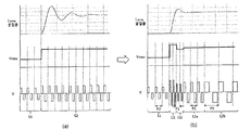
- FIGS. 11A and 11B illustrate a method of controlling a liquid lens through excess voltage supply.
- FIGS. 11A and 11B illustrate an example of supplying a driving voltage of a liquid lens through pulse amplitude modulation (PAM).
- FIG. 11A illustrates a case where a driving voltage pulse having a predetermined period is used
- FIG. 11B illustrates a case in which different periods or changes in periods of the driving voltage pulse can be controlled.
- Controlling different periods or changes in periods may be substantially the same as controlling different frequencies or changes in frequencies.
- the effective voltage Vrms may be changed by changing the driving voltage V to change from the first state S1 to the second state S2.
- the driving voltage V may change the amount of electric energy actually transmitted through a change in duty ratio in a predetermined period.
- the duty ratio in the second state S2 may be greater than the first state S1.
- An effective value (eg, root mean square, RMS) for the driving voltage V having such a waveform may be calculated as the effective voltage Vrms.
- an amplitude of the driving voltage V may be greater in the second state S2 than in the first state S1.
- a change in the refractive index of the liquid lens in the first state S1 and the second state S2 occurs.
- the refractive index of the liquid lens 28 shows an unstable wave shape as shown in the figure, and then gradually stabilizes. Can be. After inducing the movement of the interface in the liquid lens 28 and reducing the time required for the interface to stabilize, i.e., the refractive index is changed stably, the camera module or the optical device equipped with the liquid lens can perform a faster operation. Can be done.
- the period of the driving voltage having a pulse shape is controlled differently according to the states S1, O1, O2, S2a, and S2b of the liquid lens 28.
- the driving voltage V can be supplied in three periods P1, P2, and P3.
- the three periods P1, P2, and P3 have been described as an example, and the period of the driving voltage V may be variously set according to an embodiment.
- the second period P2 may be longer than the first period P1, and the third period P3 may be longer than the second period P2.
- the first period P1, which is the shortest period may be applied when there is a change in the driving voltage
- the second period P2 may be applied when the driving voltage is applied after the state change occurs.
- the third period P3, which is the longest period may be applied to the driving voltage applied in the stabilization state where the state is stabilized and it is determined that there is no change in the driving voltage.
- the first and second transition periods O1 and O2 are in two states (eg, , Between the first state S1 and the second state S2, that is, at a time of change.
- a driving voltage having a first period P1 having a short period may be applied in the first switching period O1 and the second switching period O2.
- the first switching period O1 may be described as an overshooting voltage period.
- a voltage greater than 30% higher than a target voltage may be applied.
- the magnitude of the voltage is greater than the target voltage in the second switching section O2.
- the driving voltage having a second period P2 longer than the first period P1 and corresponding to the target voltage range May be applied to the liquid lens.
- the third state S2b may be set when the target voltage is stabilized without changing the driving voltage.
- a longer period P3 of the pulsed driving voltage may be applied.
- the pulse period (operating frequency) may be further subdivided and varied.
- different pulse periods may be used.
- FIG. 11B illustrates the first switching period O1 and the second in the process of changing from the first state S1 where the effective voltage Vrms is low to the second state S2 where the effective voltage Vrms increases.
- the case where the switching section O2 exists is described as an example.
- a plurality of switching periods may be included in the process of converting the effective voltage Vrms to a low state while the effective voltage Vrms is high. For example, after applying a target voltage lower than 30% of the target voltage in the first switching section, and then applying a voltage higher than 15% higher than the target voltage in the second switching section, The movement of the interface in the lens can be made faster.
- the period of the driving voltage V can be changed in accordance with the operation state or operation mode of the inner interface of the liquid lens 28.
- the first switching period O1 and the second switching period O2 supply a driving voltage of a short period P1, and in the third state S2b in which the driving voltage is stabilized, a long period P3.
- Drive voltage can be supplied.
- the frequency of the driving voltage is increased to speed up the driving speed of the liquid lens, and thus the driving voltage for inducing the refractive index change of the liquid lens can be more quickly responded.
- the driving frequency may be lowered to reduce switching loss, thereby improving efficiency of the entire control circuit.
- the apparatus and method for controlling a liquid lens uses a short period (ie, high frequency) drive voltage to speed up the drive of the liquid lens at a time when the magnitude of the drive voltage applied to the liquid lens is different, especially when the change in the drive voltage is large.
- a plurality of switching sections to be applied can be set. For example, one of the plurality of switching sections may apply a voltage having a difference of 30% or more than a target voltage, and then apply a voltage having a difference of 15% or less of the target voltage to another.
- the holding state may be determined based on a period in which the control circuit of the liquid lens supplies a driving voltage.
- the holding state may be determined by a user's external input or a control circuit of a camera module or an optical device equipped with a liquid lens. You can also judge.
- the control circuit of the liquid lens can increase the efficiency of the control circuit by decreasing the driving frequency (ie, increasing the period).
- FIG. 12 is a view for explaining the liquid lens control circuit 50 according to the second embodiment.
- the interface 30 in the liquid lens 28 includes the common electrodes and the voltages VL1, VL2, VL3, and VL4 transmitted through the plurality of individual electrode sectors L1, L2, L3, and L4. It may be controlled corresponding to the voltage VC0 applied to (CO).
- the first to fourth Each of the individual electrodes L1, L2, L3, and L4 may mean a pair of the corresponding electrode sector and the first electrode among the first to fourth electrode sectors, and the first to fourth individual electrodes L1, L2,
- the driving voltages applied to L3 and L4 may be referred to as first to fourth driving voltages, respectively.
- the change in the movement and the shape of the interface 30 in the liquid lens 28 causes the voltage difference between the first to fourth driving voltages VL1, VL2, VL3, and VL4 and the common voltage VC0 applied to the common electrode C0. Can be caused by
- the driving voltage and the common voltages VL1, VL2, VL3, VL4 and VC0 may be applied from the liquid lens control circuit 50.
- the liquid lens control circuit 50 may determine a driving voltage to be applied to the plurality of individual electrode sectors L1, L2, L3, and L4 and the common electrode sector C0 (see FIG. 3) in the liquid lens 28. That is, the amplitude or period of the driving voltage can be determined.
- the liquid lens control circuit 50 may change a period of a driving voltage applied to the plurality of individual electrode sectors L1, L2, L3, and L4 and the common electrode sector C0.
- the liquid lens control circuit 50 includes a lens drive determination unit 56 that determines the movement of the liquid lens 28 or the diopter change of the interface 30 in the liquid lens 28, and the liquid lens 28 in response to the diopter change.
- a voltage generator 56 that determines a change in voltage to be applied to the plurality of individual electrodes L1, L2, L3, L4 and the common electrode C0, and the plurality of individual electrodes L1, L2, L3, L4.
- a driving voltage period controller 58 for changing a period of the driving voltage applied to the common electrode C0.
- the liquid lens control circuit 50 may provide information about the movement of the liquid lens 28 from the various sensors (eg, gyro sensors, etc.) included in the device in which the liquid lens 28 is mounted or the liquid lens 28 should compensate for.
- Information about the value can be received.
- a user's input through the user interface or the like causes a diopter change of the liquid lens 28
- information corresponding to the input may be transmitted to the liquid lens control circuit 50.
- the diopter change does not occur due to a sensor input or an external input, corresponding information may be transmitted to the liquid lens control circuit 50.
- the voltage generator 56 may apply the liquid lens according to the target voltages of the driving voltages VL1, VL2, VL3, VL4 and VC0. 28, the driving voltages VL1, VL2, VL3, VL4, and VC0 are changed to control the movement of the interface 30 within the plurality of individual electrodes L1, L2, L3, L4 and the common electrode C0.
- a voltage above or below a predetermined range may be applied to the target value voltage.
- the voltages VL1, VL2, VL3, and VL4 applied to the first to fourth individual electrodes L1, L2, L3, and L4 vary from 30 V to 50 V, that is, the first to fourth individual electrodes.
- the driving voltage applied to the electrodes L1, L2, L3, and L4 is adjusted from 30V to 50V, after applying a voltage 30% or more higher than the target voltage 50V, a voltage 15% or less lower than the target voltage 50V is applied. It is possible to control the switching section of.
- the first voltage VL1 supplied to the first individual electrode L1 through the voltage generator 56 may be applied with a voltage higher than a preset range or lower than a preset range.
- the switching period may be sequentially controlled to each individual electrode sector or may be controlled together in the process of changing the driving voltage supplied to the first to fourth individual electrodes L1, L2, L3, and L4. have.
- the driving voltage period control unit 58 sets a plurality of switching periods in order to speed up driving of the liquid lens and applies them during the switching period when the magnitude of the voltage applied to the liquid lens 28 is different, particularly when the voltage is large.
- the magnitude of the voltage can be controlled. For example, depending on the direction in which the driving voltage changes (rising or falling), a voltage having a difference of 30% or more from a target voltage is applied in one of the plurality of switching sections, and in another, 15% or less than the target voltage. Different voltages can be applied.
- the driving voltage is divided into a first section in which the amplitude of the driving voltage increases. It may include a second period in which the amplitude is reduced.
- the second amplitude may be between the maximum amplitude of the first section and the minimum amplitude of the second section.
- the maximum amplitude of the first period may be 130% or more of the second amplitude
- the minimum amplitude of the second period may be 85% of the second amplitude.
- the voltage period of the first period and the second period may be smaller than the period of the driving voltage applied at the first amplitude and the second amplitude.
- the period of the voltages VL1, VL2, VL3, VL4, and VC0 may be changed through the driving voltage period controller 58.
- the period of the driving voltages VL1, VL2, VL3, VL4, VC0 may be shortened, and the interface 30 may be shortened.
- the period of the driving voltages VL1, VL2, VL3, VL4 and VC0 may be long.
- the operation of the driving voltage period controller 58 may be understood through an example of changing the period of the driving voltage in the form of pulse described in the method for controlling the liquid lens of FIG. 11B.
- FIG. 13 is a waveform diagram illustrating a method of driving a liquid lens according to a second embodiment.
- the driving voltage supplied to the liquid lens may be applied through the common electrode C0 and the individual electrodes L1 to L4 (see FIG. 12).
- the driving voltage V affecting the change of the interface in the liquid lens may be substantially equal to the absolute value of the difference between the voltages applied to the common electrode C0 and the individual electrode L1.
- the driving voltage applied through the common electrode C0 and the individual electrodes L1 to L4 may use a pulse amplitude modulation (PAM) method.
- PAM pulse amplitude modulation
- an amplitude of a driving voltage in the form of a pulse may be changed corresponding to a driving voltage to be applied to the liquid lens 28 and a target driving voltage Vrms.
- the general pulse amplitude modulation (PAM) method adjusts the size of the pulse, but in FIG. 13, the pulse period as well as the pulse size may be varied.
- the driving voltage in the form of pulses applied to the common electrode C0 and the individual electrode L1 of the liquid lens 28 may not only adjust the pulse size but also have periods P1 and P2 of different pulses.
- the period P2 at the point in time when the driving voltage of a constant level is applied may be longer than the period P1 at the point in time when the level of the driving voltage is changed.
- the driving voltage for adjusting the movement of the interface in the liquid lens in a short time can speed up the operation of the liquid lens.
- the liquid fluctuation can be reduced while making the change of the driving voltage faster.
- the period of the driving voltage in the form of pulse applied to the common electrode C0 and the individual electrode L1 can be controlled. You can change the pulse period of. That is, the pulse period P1 in the same period as the first switching period O1 and the second switching period O2 described in FIG. 11B may be shorter than the pulse period P2 in other sections. Likewise, the same applies to the driving voltage described in FIG. 13.
- 14 (a) and 14 (b) are waveform diagrams for explaining a method of controlling a liquid lens through supplying an excess voltage.
- the driving voltage supplied to the liquid lens 28 may be determined by a pulse width modulation (PWM) method.
- PWM pulse width modulation
- FIG. 14A illustrates a case where an excess voltage is not used
- FIG. 14B illustrates a case where an excess voltage is used.
- the period of the driving voltages of FIGS. 14A and 14B is a constant case.
- the driving voltage of the liquid lens 28 is a main variable for determining the shape of the liquid lens interface
- the curvature or focal length of the liquid lens interface corresponding to the Vrms value of the driving voltage may be determined. Accordingly, the effective voltage Vrms may be changed by changing the driving voltage V to change from the third state S3 to the fourth state S4.
- the driving voltage V may be adjusted by adjusting the voltage applied to the common electrode or the individual electrode of the liquid lens.
- the driving voltage V may change the amount of electric energy actually transmitted through the change of the duty ratio (duty ratio) in a predetermined period.
- the duty ratio of the driving voltage in the fourth state S4 may be greater than in the third state S3.
- the duty ratio D2 in the fourth state S4 may be greater than the duty ratio D1 in the third state S3.
- An effective value (eg, root mean square, RMS) for the driving voltage V having such a waveform may be calculated as the effective voltage Vrms.
- a change in the shape of the liquid lens interface in the third state S3 and the fourth state S4 may occur, so that the focus of the liquid lens may be adjusted.
- the refractive index of the liquid lens can be stabilized slowly as shown in the form of an unstable wave as shown. .
- the camera module or optics equipped with the liquid lens can perform faster operation. have.
- the third switching section O3 and the third switching section O3 and the fourth state S4 are required.
- the four transition periods O4 may exist between two states (eg, the third state S3 and the fourth state S4), that is, at a point in time at which they change.
- the third switching period O3 may be described as an overshooting voltage period, and the third switching period O3 may apply a voltage of at least 30% higher than the target voltage.
- the magnitude of the voltage is up to 15% or less than the target voltage in the fourth switching section O4.
- a driving voltage corresponding to a target voltage range may be applied to the liquid lens.
- the duty ratios D1, D3, D4, and D2 of the third state S3, the third switching period O3, the fourth switching period O4, and the fourth state S4 are D3> D2>.
- the size may be determined in the order of D4> D1.
- FIG. 14B illustrates a third switching period O3 and a fourth switching in the process of changing from the third state S3 having a low effective voltage Vrms to a fourth state S4 where the effective voltage Vrms is increased.
- the case where the section O4 exists is described as an example.
- a plurality of switching periods may be included in the process of converting the effective voltage Vrms to a low state while the effective voltage Vrms is high. For example, after applying a voltage of up to 30% or less than the target voltage in the third switching section, and then applying a voltage up to 15% or more above the target voltage in the fourth switching section. The movement of the liquid lens can be made faster.
- the present invention is not limited thereto, and additional switching sections may exist.
- the apparatus and method for controlling a liquid lens can set a plurality of switching sections in order to speed up the driving of the liquid lens when the magnitude of the driving voltage applied to the liquid lens is different, especially when the amount of change in the driving voltage is large.
- one of the plurality of switching sections may apply a voltage having a difference of 30% or more than a target voltage, and then apply a voltage having a difference of 15% or less of the target voltage to another.
- 15 (a) and 15 (b) are waveform diagrams for explaining a method of controlling a liquid lens through supplying an excess voltage according to an embodiment.
- the driving voltage supplied to the liquid lens 28 may be determined by a pulse width modulation (PWM) method.
- PWM pulse width modulation
- 15A illustrates a case where no overvoltage is used
- FIG. 15B illustrates a case where overvoltage is used.
- FIG. 15B illustrates a case in which the period of the driving voltage is varied.
- FIG. 15 (a) the same as in FIG. 14 (a).
- the third switching period O3 and the fourth switching period ( O4) may exist between two states (eg, the third state S3 and the fourth state S4), that is, at a point in time at which it changes.
- the third switching period O3 may be described as an overshooting voltage period, and the third switching period O3 may apply a voltage of 30% or more higher than a target voltage.
- the magnitude of the voltage is greater than the target voltage in the fourth switching section O4. By applying a voltage lower than%, the application of the excess voltage of the initial driving can be reduced.
- a driving voltage corresponding to a target voltage range may be applied to the liquid lens.
- the pulse period P4 of the driving voltage applied to the liquid lens in the third switching period O3 and the fourth switching period O4 is applied to the liquid lens in the third state S3 and the fourth state S4. It may be shorter than the pulse period (P5) of the driving voltage to be.
- the pulse period P4 of the drive voltage can be shortened, and in the state where there is no change in the drive voltage, the pulse period P5 of the drive voltage can be increased.
- FIG. 15B illustrates the third switching period O3 and the fourth in the process of changing from the third state S3 having the low effective voltage Vrms to the fourth state S4 at which the effective voltage Vrms increases.
- the case where the switching section O4 exists is described as an example.
- a plurality of switching periods may be included in the process of converting the effective voltage Vrms to a low state while the effective voltage Vrms is high. For example, after applying a voltage lower than 30% below the target voltage in the third switching section, and applying a voltage higher than 15% higher than the target voltage in the fourth switching section, the liquid lens is applied. Can make the movement faster.
- the apparatus and method for controlling a liquid lens provide a plurality of switching in order to speed up the driving of the liquid lens when the magnitude of the driving voltage applied to the liquid lens is changed, particularly when the driving voltage is large. You can set the interval.
- one of the plurality of switching sections may apply a voltage having a difference of 30% or more than a target voltage, and then apply a voltage having a difference of 15% or less of the target voltage to another.
- FIG. 15B an embodiment having a different pulse period (operating frequency) corresponding to a section without a change in driving voltage and a section with a change has been described, but according to the embodiment, a pulse period (operating frequency) Can be further refined and diversified.
- a pulse period operating frequency
- 16 is a block diagram of a liquid lens control circuit according to a third embodiment.
- the interface 30 of the liquid lens 28 includes the voltages VL1, VL2, VL3, and VL4 transmitted to the plurality of individual electrode sectors L1, L2, L3, and L4 and the common electrode.
- the voltage VC0 transferred to the CO may be controlled to correspond to the driving voltage formed.
- the change in the position, movement, or shape of the interface 30 in the liquid lens 28 may include the first to fourth voltages VL1, VL2, VL3, and VL4 and the common electrode C0 applied to the first to fourth individual electrodes. May occur due to the voltage difference of the voltage VC0 applied to
- the voltages VL1, VL2, VL3, VL4, VC0 may be applied from the liquid lens control circuit 50.
- the liquid lens control circuit 50 controls the amount of diopter change at the interface in the liquid lens or the plurality of individual electrodes L1, L2, L3, L4 and the common electrode C0 in FIG. 3 to change the diopter.
- the voltage applied to can be controlled.
- the liquid lens control circuit 50 may set and control the switching period in the process of changing the driving voltage by applying a voltage to the plurality of individual electrodes L1, L2, L3, L4 and the common electrode C0. .
- the liquid lens control circuit 50 may include a lens driving determination unit 54 that determines the amount of diopter change at the interface 30 of the liquid lens 28, and a plurality of individual electrode sectors L1 of the liquid lens 28 in response to the amount of diopter change.
- the voltage generator 56 for controlling the voltage to be applied to each of the L2, L3, and L4 and the common electrode sector C0, and the plurality of individual electrode sectors L1, L2, L3, and L4 in response to the diopter change amount.
- a switching voltage controller 59 may be configured to control at least one switching section when the driving voltage changes in the sector C0.
- the liquid lens control circuit 50 may receive information about the movement of the liquid lens 28 from various sensors (eg, a gyro sensor) included in the device on which the liquid lens is mounted. In addition, when a user's input through the user interface or the like generates the diopter change amount of the liquid lens 28, information corresponding to the input may be transmitted to the liquid lens control circuit 50.
- the voltages VL1, VL2, VL3, VL4, and VC0 corresponding to the plurality of individual electrodes in the liquid lens 28 are determined.
- L1, L2, L3, and L4 and the common electrode C0 may be applied to each.
- the switching voltage controller 59 may set the plurality of individual electrodes L1, L2, L3, and L4 and the common electrode C0 to a predetermined range or more, in accordance with the target voltage of the liquid lens driving voltage. Alternatively, the following voltages can be applied.
- the switching section may be controlled by applying a voltage 15% or less lower than the target voltage of 50V.
- the first driving voltage VL1 supplied to the first individual electrode L1 may be applied to a first driving voltage VL1, which is higher than a target value voltage or lower than a predetermined range, through the switching voltage controller 59 that controls the switching period. Can be.
- the switching period may be sequentially controlled to each individual electrode or may be controlled together in the process of changing the voltage supplied to the first to fourth individual electrodes L1, L2, L3, and L4.
- the switching voltage control unit 59 sets a plurality of switching periods in order to speed up driving of the liquid lens when the driving voltage applied to the liquid lens 28 is different, particularly when the amount of change in the driving voltage is large.
- the magnitude of the applied voltage can be controlled. For example, depending on the direction in which the driving voltage changes (rising or falling), one of the plurality of switching sections may apply a voltage having a difference of at least 30% or more from the target voltage, and the other than the target voltage. Voltages up to 15% or less can be applied.
- 17A and 17B are waveform diagrams for describing a method of driving a liquid lens according to a third embodiment.
- the driving voltage supplied to the liquid lens 28 may be applied through the common electrode C0 and the individual electrodes L1 to L4 (see FIG. 16).
- the driving voltage V affecting the change of the interface in the liquid lens may be substantially equal to the absolute value of the difference between the voltages applied to the common electrode C0 and the individual electrode L1.
- the driving voltage applied through the common electrode C0 and the individual electrodes L1 to L4 uses a pulse width modulation (PWM) method.
- PWM pulse width modulation
- the duty ratio (duty ratio) of the driving voltage in the form of a pulse may be changed corresponding to the driving voltage to be applied to the liquid lens and the target driving voltage Vrms.
- the general pulse width modulation (PWM) method adjusts the duty ratio of a pulse, but in FIG. 17, the pulse period (operating frequency) may be changed in addition to the duty ratio of the pulse.
- the driving voltage in the form of pulses applied to the common electrode C0 and the individual electrode L1 of the liquid lens may not only have a pulse width adjusted but may have different pulse periods P4 and P5.
- the period P5 of the section in which the constant level driving voltage is applied may be longer than the period P4 in the section in which the level of the driving voltage is changed.
- changing the driving voltage for adjusting the movement of the interface in the liquid lens in a short time can speed up the operation of the liquid lens.
- a change in the driving voltage can be made faster by applying a voltage higher than the target driving voltage and then applying a lower voltage.
- the period of the driving voltage in the form of pulses applied to the common electrode C0 and the individual electrode L1 is faster.
- the pulse period P4 in the same period as the third switching period O3 and the fourth switching period O4 described in FIG. 15B may be shorter than the pulse period P5 in other sections.
- FIGS. 18A and 18B are waveform diagrams for explaining a method of controlling a driving voltage of a liquid lens. Specifically, the embodiment described with reference to FIGS. 18A and 18B may adjust a period (operating frequency) unlike a general pulse width modulation (PWM) method.
- PWM pulse width modulation
- the duty ratio and the period of the driving voltage applied to the common electrode C0 and the individual electrode L1 are changed.
- the period of the driving voltage applied to the common electrode C0 and the individual electrode L1 is changed from the long period P41 to the short period P42 while the duty ratio of 50% is changed to the duty ratio of 75%.
- the driving voltage V affecting the interface of the liquid lens is the difference (absolute value) of the voltages applied to the common electrode C0 and the individual electrode L1.
- the duty ratio of the driving voltages applied to the common electrode C0 and the individual electrode L1 By controlling the duty ratio of the driving voltages applied to the common electrode C0 and the individual electrode L1, the magnitude of the driving voltage V affecting the interface of the liquid lens can be adjusted.
- the period (operating frequency) of the driving voltages applied to the common electrode C0 and the individual electrode L1 more precise and precise control (noise, reduction of damping, etc.) can be realized.
- the duty ratios of the driving voltages applied to the common electrode C0 and the individual electrode L1 are equally changed (from 50% to 75%) has been described, but the common electrode C0 and the individual electrode L1 have been described.
- the duty ratio of the driving voltage applied to may be adjusted differently.
- the duty ratio of the common electrode C0 is 50%, but the duty ratio of the individual electrode L1 may be 75%.
- the duty ratios of the driving voltages applied to the individual electrodes L1 to L4 may be the same or may be different from each other. In this way, the magnitudes of the driving voltages V applied through the individual electrodes L1 to L4 and the common electrode C0 of the liquid lens can be adjusted differently or identically, thereby controlling the focus of the liquid lens. can do.
- the driving voltage period of the common electrode C0 is a long period P43. Is maintained as it is, and the driving voltage V that affects the interface of the liquid lens is adjusted by changing the driving voltage period of the individual electrode L1 from the long period P43 to the short period P44.
- the duty ratios (eg, 50%) of the driving voltages applied to the common electrode C0 and the individual electrode L1 are the same, the periods of the driving voltages applied to the common electrode C0 and the individual electrode L1 are different from each other. can do. That is, the period of the driving voltages applied to the common electrode C0 and the individual electrode L1 may be equally or differently adjusted.
- the periods of the driving voltages applied to the individual electrodes L1 to L4 may all be different or may be the same. In this way, the magnitudes of the driving voltages V applied through the individual electrodes L1 to L4 and the common electrode C0 of the liquid lens can be adjusted differently or identically, thereby controlling the focus of the liquid lens. can do.
- optical device including the above-described camera module
- the optical device may include a device capable of processing or analyzing an optical signal.
- optical instruments may include camera / video devices, telescope devices, microscope devices, interferometer devices, photometer devices, polarimeter devices, spectrometer devices, reflectometer devices, autocollimator devices, lens meter devices, and the like, and may include liquid lenses.
- Embodiments of the present invention can be applied to an optical device capable of.
- the optical device may be implemented as a portable device such as a smartphone, a notebook computer, a tablet computer.
- the optical device may include a camera module, a display unit for outputting an image, and a main body housing in which the camera module and the display unit are mounted.
- the optical device may further include a memory unit in which a communication module capable of communicating with other devices may be mounted in the body housing and store data.
- the method according to the embodiment described above may be stored in a computer-readable recording medium that is produced as a program for execution in a computer.
- Examples of the computer-readable recording medium may include ROM, RAM, CD-ROM, magnetic tape. , Floppy disks, optical data storage, and the like.
- the computer readable recording medium can be distributed over network coupled computer systems so that the computer readable code is stored and executed in a distributed fashion.
- functional programs, codes, and code segments for implementing the above-described method may be easily inferred by programmers in the art to which the embodiments belong.
- the liquid lens control circuit includes a camera / video device, a telescope device, a microscope device, an interferometer device, a photometer device, a polarimeter device, a spectrometer device, a reflectometer device, an autocollimator device, a lens meter device, a smartphone, a notebook computer, It can be used in a portable device such as a tablet computer.
Abstract
실시 예의 액체 렌즈 제어 회로는 공통 전극과 복수의 개별전극을 포함하는 액체 렌즈; 액체 렌즈 내 복수의 개별 전극 및 공통 전극에 전압을 공급하는 전압 생성부; 및 복수의 개별 전극 각각에 전압을 순차적으로 공급하도록 타이밍을 제어하는 제어부를 포함한다.
Description
실시 예는 액체렌즈 및 이를 포함하는 카메라 모듈 및 광학기기에 관한 것이다. 보다 구체적으로, 실시 예는 전기 에너지를 이용하여 초점 거리를 조정할 수 있는 액체 렌즈를 제어하기 위한 액체 렌즈 제어 모듈 또는 액체 렌즈 제어 장치 또는 액체 렌즈 제어 회로를 포함하는 카메라 모듈 및 광학기기에 관한 것이다.
휴대용 장치의 사용자는 고해상도를 가지며 크기가 작고 다양한 촬영 기능을 가지는 광학 기기를 원하고 있다. 예를 들어, 다양한 촬영 기능으로서, 오토 포커싱(Auto-Focusing, AF) 기능, 손떨림 보정 내지 영상 흔들림 방지(Optical Image Stabilizer, OIS) 기능 등이 있다.
전술한 촬영 기능은 여러 개의 렌즈를 조합해서 직접 렌즈를 움직이는 방법을 통해 구현될 수 있으나, 렌즈의 수를 증가시킬 경우 광학 기기의 크기가 커질 수 있다. AF 기능과 OIS 기능은, 렌즈 홀더에 고정되어 광축이 정렬된 여러 개의 렌즈 모듈이, 광축 또는 광축과 수직하는 방향으로 이동하거나 틸팅(Tilting)하여 수행되고, 렌즈 모듈을 구동시키기 위해 별도의 렌즈 구동 장치가 사용된다. 그러나, 렌즈 구동 장치는 전력 소모가 높으며, 전체 두께가 두꺼워 진다. 따라서 두 가지 액체의 계면의 곡률을 전기적으로 조절하여 AF 기능과 OIS 기능을 수행하는 액체 렌즈에 대한 연구가 이루어지고 있다.
실시 예는 전기 에너지를 이용하여 초점 거리를 조정할 수 있는 액체 렌즈를 포함하는 카메라 모듈에서 액체 렌즈를 구동하기 위한 전압을 복수의 개별 전극에 순차적으로 또는 점진적으로 공급하여 액체 렌즈 내 계면의 움직임을 안정화시킬 수 있는 장치와 방법을 제공할 수 있다.
또한, 실시 예는 액체 렌즈의 복수의 개별 전극에 순차적으로 전기 에너지를 인가하여 액체 렌즈 내 계면을 제어하는 과정에서 계면의 자유롭고 유연한 움직임으로 인해 계면이 안정화되는 데 소요되는 시간을 줄일 수 있어, 액체 렌즈를 포함하는 카메라 모듈 또는 광학기기 등의 초점 이동에 따른 동작 시간을 줄일 수 있다.
또한, 실시 예는, 전기 에너지를 이용하여 초점 거리를 조정할 수 있는 액체 렌즈를 포함하는 카메라 모듈에서 액체 렌즈를 구동하기 위한 전압 펄스를 제어하여 복수의 개별 전극에 공급함으로써 액체 렌즈 내 계면의 움직임을 안정화시킬 수 있는 장치와 방법을 제공할 수 있다.
또한, 실시 예는 액체 렌즈에 인가되는 펄스 형태의 구동 전압을 제어하기 위해, 액체 렌즈의 상태(예, 디옵터 변화 여부 등)에 따라 구동 전압의 펄스 주기를 조절하여 액체 렌즈의 동작 속도를 높일 수 있는 장치와 방법을 제공할 수 있다.
또한, 실시 예는 액체 렌즈를 제어하는 동안 구동 전압의 펄스 주기를 조절하여 스위칭 회로의 부담을 줄일 수 있어 액체 렌즈의 제어 회로의 소비전력을 줄일 수 있는 장치와 방법을 제공할 수 있다.
실시 예에서 이루고자 하는 기술적 과제들은 이상에서 언급한 기술적 과제들로 제한되지 않으며, 언급하지 않은 또 다른 기술적 과제들은 아래의 기재로부터 본 발명이 속하는 기술 분야에서 통상의 지식을 가진 자에게 명확하게 이해될 수 있을 것이다.
일 실시 예에 따른 액체 렌즈 제어 회로는 공통 전극과 복수의 개별전극을 포함하는 액체 렌즈; 상기 액체 렌즈 내 복수의 개별 전극 및 공통 전극에 전압을 공급하는 전압 생성부; 및 상기 복수의 개별 전극 각각에 상기 전압을 순차적으로 공급하도록 타이밍을 제어하는 제어부를 포함할 수 있다.
또한, 상기 복수의 개별전극은 제1 개별 전극, 제2 개별전극, 제3 개별전극 및 제4 개별전극을 포함하고, 상기 제어부는 상기 제1 개별 전극에 상기 전압을 인가 한 후 상기 제2 개별전극에 상기 전압을 인가하고, 상기 제2 개별전극에 상기 전압을 인가한 후 상기 제3 개별전극에 상기 전압을 인가하고, 상기 제3 개별전극에 상기 전압을 인가한 후 상기 제4 개별전극에 상기 전압을 인가할 수 있다.
또한, 상기 제1 개별전극과 상기 제2 개별전극은 상기 액체렌즈 중심부를 기준으로 서로 대칭되는 위치에 배치될 수 있다.
또한, 상기 제어부는 상기 전압을 상기 복수의 개별 전극 각각에 기 설정된 시간 간격을 두고 순차적으로 인가할 수 있다.
또한, 상기 타이밍은 상기 전압의 주기의 정수배일 수 있다.
또한, 상기 제어부는 상기 제1개별 전극 내지 상기 제4개별 전극으로 인가되는 전압을 높은 전압에서 낮은 전압 순서로 인가할 수 있다.
다른 실시 예에 따른 액체 렌즈 제어 회로는 공통 전극 및 복수의 개별전극을 포함하는 액체 렌즈; 입력 전압의 크기를 제어하여 출력 전압을 생성하는 전압 생성부; 및 상기 전압 생성부의 출력 전압을 이용하여 상기 공통 전극 및 복수의 개별전극에 공급되는 전압의 주기를 제어하는 전압 주기 제어부를 포함할 수 있다.
또한, 상기 공통 전극과 상기 복수의 개별 전극 중 적어도 하나에 인가되는 전압이 변할 때, 상기 전압 주기는 기 설정된 제1주기에서 상기 제1주기보다 짧은 제2주기로 변화되는 구간을 포함할 수 있다.
또한, 상기 제2주기로 변화되는 구간 이후에 상기 제1주기로 변화되는 구간을 포함할 수 있다.
또한, 상기 제2 주기의 전압주기를 갖는 구간의 전압의 진폭은 서로 다른 제1 진폭과 제2 진폭을 포함할 수 있다.
또한, 상기 제2 주기로 변화되는 구간 이후에 상기 제1주기로 변화되는 구간의 진폭은 상기 상기 제1 진폭과 상기 제2 진폭 사이일 수 있다.
또한, 상기 복수의 개별 전극 중 어느 하나에 인가되는 전압의 진폭과 상기 공통 전극에 인가되는 전압의 진폭은 서로 대응될 수 있다.
또 다른 실시예에 따른 액체 렌즈 제어 회로는 공통 전극 및 복수의 개별전극을 포함하는 액체 렌즈; 상기 액체 렌즈를 구동하는 구동 전압을 생성하는 전압 생성부; 및 상기 공통 전극 과 복수의 개별전극 중 하나의 개별전극 사이에 인가되는 구동 전압의 진폭이 제1 진폭에서 제2 진폭으로 변경될 때, 상기 구동전압은 상기 구동전압의 진폭이 증가하는 제1 구간과 진폭이 감소하는 제2 구간을 포함하고, 상기 제2진폭은 상기 제1 구간의 최대진폭과 상기 제2 구간의 최소 진폭 사이일 수 있다.
또한, 상기 제1구간과 제2구간의 전압 주기는 상기 제1진폭과 상기 제2진폭으로 인가된 구동전압의 주기보다 작을 수 있다.
또한, 상기 제1진폭이 상기 제2진폭보다 작은 경우, 상기 제1구간의 최대 진폭은 상기 제2진폭의 130%이상이고, 상기 제2구간의 최소진폭은 상기 제2 진폭의 85%이하일 수 있다.
또 다른 실시예에 따른 액체 렌즈 제어 회로는 공통 전극 및 복수의 개별전극을 포함하는 액체 렌즈; 상기 액체 렌즈를 구동하는 구동 전압을 생성하는 전압 생성부; 및 상기 공통 전극 과 복수의 개별전극 중 하나의 개별전극 사이에 인가되는 구동 전압의 Vrms 값이 제1 V rms 값에서 제2 Vrms 값으로 변경될 때, 상기 구동전압의 듀티비가 변경된 제1 구간과 상기 제1 구간과 다른 듀티비를 갖는 제2 구간을 포함하고, 제1 구간 또는 제2 구간 중 적어도 하나의 듀티비는 상기 제2 Vrms 값을 갖는 구간에서의 듀티비 보다 큰 듀티비를 가질 수 있다.
또한, 상기 제2 Vrms값이 상기 제1 Vrms값보다 큰 경우, 상기 제2 Vrms 값는 갖는 구간의 듀티비는 상기 제1구간의 듀티비 보다 작을 수 있다.
또한, 상기 제2 Vrms값이 상기 제1 Vrms값보다 큰 경우, 상기 제2 Vrms 값는 갖는 구간의 듀티비는 상기 제1 Vrms 값는 갖는 구간의 듀티비 보다 클 수 있다.
또한, 상기 제1 Vrms값이 상기 제2 Vrms값보다 큰 경우, 상기 제2 Vrms 값는 갖는 구간의 듀티비는 상기 제1구간의 듀티비 보다 클 수 있다.
또한, 상기 제2 Vrms값이 상기 제1 Vrms값보다 작은 경우, 상기 제2 Vrms 값는 갖는 구간의 듀티비는 상기 제1 Vrms 값는 갖는 구간의 듀티비 보다 작을 수 있다.
또한, 상기 구동 전압의 펄스의 높이와 주기는 일정할 수 있다.
또한, 상기 제1구간에서 제3 Vrms 값을 갖고, 상기 제2 구간에서 제4 Vrms 값을 갖고, (제3 Vrms값 > 제2 Vrms 값> 제4 Vrms 값> 제1 Vrms값)의 수식을 만족할 수 있다.
또한, 상기 제1구간에서 제3 Vrms 값을 갖고, 상기 제2 구간에서 제4 Vrms 값을 갖고, (제1 Vrms값 > 제4 Vrms 값> 제2 Vrms 값> 제3 Vrms값)의 수식을 만족할 수 있다.
또한, 상기 공통 전극과 상기 복수의 개벌 전극 중 적어도 하나에 인가되는 전압이 변할 때, 상기 구동 전압 주기는 기 설정된 제1주기에서 상기 제1주기보다 짧은 제2주기로 변화되는 구간을 포함할 수 있다.
또한, 제3 Vrms 값은 제2 Vrms 값의 130% 이내이고, 제4 Vrms 값은 제2 Vrms 값의 85% 이내일 수 있다.
또한, 상기 구동 전압의 펄스의 폭 또는 주기가 가변될 수 있다.
상기 본 발명의 양태들은 본 발명의 바람직한 실시 예들 중 일부에 불과하며, 본원 발명의 기술적 특징들이 반영된 다양한 실시 예들이 당해 기술분야의 통상적인 지식을 가진 자에 의해 이하 상술할 본 발명의 상세한 설명을 기반으로 도출되고 이해될 수 있다.
실시 예에 따른 장치에 대한 효과에 대해 설명하면 다음과 같다.
실시 예는 초점 거리를 조정할 수 있는 액체 렌즈의 구동 전압을 순차적으로 인가하여, 액체 렌즈의 급격한 초점 이동에 따른 부작용을 줄일 수 있다.
또한, 실시 예는 액체 렌즈의 제어에 따른 계면의 움직임이 보다 안정적이면서 민첩해질 수 있어 움직임이 크고 잦은 카메라 모듈 또는 광학기기 등에 액체 렌즈를 탑재할 수 있다.
또한, 실시 예는 초점 거리를 조정할 수 있는 액체 렌즈의 구동 전압의 펄스 주기 및 펄스의 진폭(amplitude)를 제어하여 복수의 개별 전극에 인가하여, 액체 렌즈의 급격한 초점 이동에 따른 계면의 이동을 보다 빠르고 안정적으로 얻을 수 있다.
또한, 실시 예는 초점 거리를 조정할 수 있는 액체 렌즈의 구동 전압의 펄스 펄스의 듀티비를 제어하여 구동 전압의 변화 시 초과전압과 과소전압을 복수의 개별 전극에 인가하여, 액체 렌즈의 급격한 초점 이동에 따른 계면의 이동을 보다 빠르고 안정적으로 얻을 수 있다.
실시 예에서 얻을 수 있는 효과는 이상에서 언급한 효과들로 제한되지 않으며 언급하지 않은 또 다른 효과들은 아래의 기재로부터 본 발명이 속하는 분야에서 통상의 지식을 가진 자에게 명확하게 이해될 수 있을 것이다.
도 1은 카메라 모듈의 일 례를 나타내는 도면이다.
도 2는 카메라 모듈에 포함된 렌즈 어셈블리의 예시적인 단면도를 나타낸다.
도 3 (a) 및 (b)는 구동 전압에 대응하여 초점 거리가 조정되는 액체 렌즈의 사시도 및 등가회로를 각각 나타낸다.
도 4는 액체 렌즈의 예시적인 단면도를 나타낸다.
도 5 (a) 및 (b)는 액체 렌즈의 렌즈 보정 방법을 설명하기 위한 도면이다.
도 6 (a) 내지(c)는 액체 렌즈 내 계면의 변화를 설명하기 위한 도면이다.
도 7 (a) 및 (b)는 액체 렌즈 내 계면의 움직임을 설명하기 위한 도면이다.
도 8은 제1 실시 예에 의한 액체 렌즈 제어 회로의 블럭도를 나타낸다.
도 9 (a) 및 (b)는 제1 실시 예에 의한 액체 렌즈 제어 회로에 의해 액체 렌즈에 인가되는 구동 전압을 설명하기 위한 파형도를 나타낸다.
도 10 (a) 및 (b)는 액체 렌즈가 탑재된 휴대용 장치의 움직임에 대응하여 액체 렌즈에 구동 전압이 인가되는 과정을 설명하기 위한 도면이다.
도 11은 초과전압 공급을 통한 액체 렌즈의 제어 방법을 설명하기 위한 도면이다.
도 12는 제2 실시 예에 의한 액체 렌즈 제어 회로의 블럭도를 나타낸다.
도 13은 제2 실시 예에 의한 액체 렌즈의 구동 방법을 설명하기 위한 파형도이다.
도 14 (a) 및 (b)는 제2 실시 예에 의한 초과 전압 공급을 통한 액체 렌즈의 제1 제어 방법을 설명하기 위한 파형도이다.
도 15 (a) 및 (b)는 제2 실시 예에 의한 초과 전압 공급을 통한 액체 렌즈의 제2 제어 방법을 설명하기 위한 파형도이다.
도 16은 제3 실시 예에 의한 액체 렌즈 제어 회로의 블럭도를 나타낸다.
도 17a 및 도 17b는 제3 실시 예에 의한 액체 렌즈의 구동 방법을 설명하기 위한 파형도이다.
도 18 (a) 및 (b)는 제3 실시 예에 의한 액체 렌즈의 구동 전압을 제어하는 방법을 설명하기 위한 파형도이다.
이하, 첨부된 도면들을 참조하여 실시 예를 상세히 설명한다. 실시 예는 다양한 변경을 가할 수 있고 여러 가지 형태를 가질 수 있는 바, 특정 실시 예들을 도면에 예시하고 본문에 상세하게 설명하고자 한다. 그러나 이는 실시 예를 특정한 개시 형태에 대해 한정하려는 것이 아니며, 실시 예의 사상 및 기술 범위에 포함되는 모든 변경, 균등물 내지 대체물을 포함하는 것으로 이해되어야 한다.
"제1", "제2" 등의 용어는 다양한 구성요소들을 설명하는 데 사용될 수 있지만, 상기 구성요소들은 상기 용어들에 의해 한정되어서는 안 된다. 상기 용어들은 하나의 구성요소를 다른 구성요소로부터 구별하는 목적으로 사용된다. 또한, 실시 예의 구성 및 작용을 고려하여 특별히 정의된 용어들은 실시 예를 설명하기 위한 것일 뿐이고, 실시 예의 범위를 한정하는 것이 아니다.
실시 예의 설명에 있어서, 각 element의 "상(위)" 또는 "하(아래)(on or under)"에 형성되는 것으로 기재되는 경우에 있어, 상(위) 또는 하(아래)(on or under)는 두 개의 element가 서로 직접(directly)접촉되거나 하나 이상의 다른 element가 상기 두 element사이에 배치되어(indirectly) 형성되는 것을 모두 포함한다. 또한 “상(위)" 또는 "하(아래)(on or under)”로 표현되는 경우 하나의 element를 기준으로 위쪽 방향뿐만 아니라 아래쪽 방향의 의미도 포함할 수 있다.
또한, 이하에서 이용되는 "상/상부/위" 및 "하/하부/아래" 등과 같은 관계적 용어들은, 그런 실체 또는 요소들 간의 어떠한 물리적 또는 논리적 관계 또는 순서를 반드시 요구하거나 내포하지는 않으면서, 어느 한 실체 또는 요소를 다른 실체 또는 요소와 구별하기 위해서 이용될 수도 있다.
도 1은 카메라 장치(또는, 카메라 모듈)를 예시적으로 나타내는 도면이다.
도 1에 도시된 바와 같이, 카메라 모듈은 렌즈 어셈블리(22) 및 이미지 센서(26)를 포함할 수 있다. 카메라 모듈은 제어 회로(24)를 더 포함할 수 있다.
렌즈 어셈블리(22)는 인가되는 전압에 대응하여 초점거리가 조정되는 액체 렌즈를 포함할 수 있다. 렌즈 어셈블리(22)는 공통 단자와 복수의 개별 단자 사이에 인가되는 구동 전압에 대응하여 초점 거리가 조정되는 제1 렌즈(또는, 액체 렌즈)를 포함하는 복수의 렌즈를 포함할 수 있다.
제어 회로(24)는 제1 렌즈에 구동 전압을 공급할 수 있다.
이미지 센서(26)는 렌즈 어셈블리(22)에 정렬되며 렌즈 어셈블리(22)를 통해 전달되는 광을 전기 신호로 변환할 수 있다.
도 1을 참조하면, 카메라 모듈은 하나의 인쇄회로기판(PCB) 상에 형성된 제어 회로(24) 및 이미지 센서(26)와 복수의 렌즈를 포함하는 렌즈 어셈블리(22)를 포함할 수 있으나, 이는 하나의 예에 불과할 뿐 실시 예의 범위를 한정하지 않는다. 제어 회로(24)의 구성은 카메라 모듈에 요구되는 사양에 따라 다르게 설계될 수 있다. 특히, 액체 렌즈에 인가되는 전압의 크기를 줄일 경우, 제어 회로(24)는 하나의 칩(single chip)으로 구현할 수 있다. 이를 통해, 휴대용 장치에 탑재되는 카메라 모듈의 크기를 더욱 줄일 수 있다.
도 2는 카메라 장치(또는, 카메라 모듈)에 포함된 렌즈 어셈블리(22)의 예시적인 단면도를 나타낸다.
도 2에 도시된 바와 같이, 렌즈 어셈블리(22)는 제1 렌즈부(100), 제2 렌즈부(200), 액체 렌즈부(300), 렌즈 홀더(400) 및 연결부(500)를 포함할 수 있다.
연결부(500)는 이미지 센서(26)와 액체 렌즈를 전기적으로 연결하며, 후술할 기판, 와이어 또는 전선 등을 포함할 수 있다. 도시된 렌즈 어셈블리(22)의 구조는 하나의 예에 불과하며, 카메라 모듈에서 요구되는 사양에 따라 렌즈 어셈블리(22)의 구조는 달라질 수 있다. 예를 들어, 도 2에 도시된 예에서는 액체 렌즈부(300)가 제1 렌즈부(100)와 제2 렌즈부(200) 사이에 위치하지만, 다른 실시 예에 의하면, 액체 렌즈부(300)가 제1 렌즈부(100)보다 상부(전면)에 위치할 수도 있고, 제1 렌즈부(100) 또는 제2 렌즈부(200) 중 적어도 하나는 생략될 수도 있다. 특히, 렌즈 어셈블리(22)에 인가되는 동작 전압의 크기를 줄일 경우, 제어 회로(24)는 하나의 칩(single chip)으로 구현할 수 있다. 이를 통해, 휴대용 장치에 탑재되는 카메라 장치의 크기를 더욱 줄일 수 있다.
계속해서 도 2를 참조하면, 제1 렌즈부(100)는 렌즈 어셈블리(22)의 전방에 배치되고, 렌즈 어셈블리(22)의 외부로부터 광이 입사하는 부위이다. 제1 렌즈부(100)는 적어도 하나의 렌즈를 포함할 수 있고, 또는 2개 이상의 복수의 렌즈들이 중심축(PL)을 기준으로 정렬하여 광학계를 형성할 수도 있다.
제1 렌즈부(100) 및 제2 렌즈부(200)는 렌즈 홀더(400)에 장착될 수 있다. 이때, 렌즈 홀더(400)에는 복수의 관통공이 형성되고, 복수의 관통공에 제1 렌즈부(100) 및 제2 렌즈부(200)가 각각 배치될 수 있다. 또한, 렌즈 홀더(400)에 제1 렌즈부(100)와 제2 렌즈부(200)가 배치되는 사이 공간에는 액체 렌즈부(300)가 삽입되어 배치될 수 있다.
한편, 제1 렌즈부(100)는 고체렌즈(110)를 포함할 수 있다. 고체렌즈(110)는 렌즈 홀더(400) 외부로 돌출되어 외부에 노출될 수 있다. 고체렌즈(110)가 외부에 노출됨으로 인해 렌즈 표면이 손상될 수 있다. 만약 렌즈 표면이 손상될 경우, 카메라 모듈에서 촬영되는 이미지의 화질이 저하될 수 있다. 고체렌즈(110)의 표면손상을 방지, 억제하기 위해, 커버 글래스를 배치시키거나 코팅층을 형성하거나 표면손상을 방지하기 위한 내마모성 재질로 고체렌즈(100)를 구현하는 방법 등이 적용될 수 있다.
제2 렌즈부(200)는 제1 렌즈부(100) 및 액체 렌즈부(300)의 후방에 배치되고, 외부로부터 제1 렌즈부(100)로 입사하는 광은 액체 렌즈부(300)를 투과하여 제2 렌즈부(200)로 입사할 수 있다. 제2 렌즈부(200)는 제1 렌즈부(100)와 이격되어 렌즈 홀더(400)에 형성되는 관통공에 배치될 수 있다.
제2 렌즈부(200)는 적어도 하나의 렌즈를 포함할 수 있고, 2개 이상의 복수의 렌즈들이 포함되는 경우 중심축(PL)을 기준으로 정렬하여 광학계를 형성할 수도 있다.
한편, 액체 렌즈부(300)는 제1 렌즈부(100)와 제2 렌즈부(200) 사이에 배치되고, 렌즈 홀더(400)의 삽입구(410)를 통해 삽입될 수 있다. 삽입구(410)는 렌즈 홀더(400)의 측면의 일부 영역이 개방되어 형성될 수 있다. 즉, 액체 렌즈부(300)는 렌즈 홀더(400)의 측면의 삽입구(410)를 통해 삽입되어 배치될 수 있다. 액체 렌즈부(300)는 제1 렌즈부(100) 및 제2 렌즈부(200)와 함께 중심축(PL)을 기준으로 정렬될 수 있다.
액체 렌즈부(300)는 렌즈 영역(310)을 포함할 수 있다. 렌즈 영역(310)은 제1 렌즈부(100)를 통과한 광이 투과하는 부위이고, 적어도 일부에 액체를 포함할 수 있다. 예를 들면, 렌즈 영역(310)에 두 가지 종류 즉, 도전성 액체와 비도전성 액체가 함께 배치될 수 있고, 도전성 액체와 비도전성 액체는 서로 섞이지 않고 경계면을 이룰 수 있다. 연결부(500)를 통해 인가되는 구동 전압에 의해 도전성 액체와 비도전성 액체의 경계면이 변형되어 액체 렌즈 계면의 곡률 또는 액체 렌즈의 초점거리가 변경될 수 있다. 이러한 경계면의 변형, 곡률변경이 제어되면, 액체 렌즈부(300)와 이를 포함하는 카메라 모듈은 오토포커싱 기능, 손떨림 보정기능 등을 수행할 수 있다.
도 3 (a) 및 (b)는 구동 전압에 대응하여 초점 거리가 조정되는 액체 렌즈를 설명하기 위한 도면이다. 구체적으로, 도 3(a)는 렌즈 어셈블리(22, 도 2참조)에 포함된 제1 렌즈(또는, 액체 렌즈)(28)를 설명하고, 도 3(b)는 제1 렌즈(28)의 등가회로를 나타낸다.
먼저 도 3(a)를 참조하면, 구동 전압에 대응하여 초점 거리가 조정되는 액체 렌즈(28)는 동일한 각 거리를 가지고 4개의 서로 다른 방향에 배치된 개별 단자(L1, L2, L3, L4)를 통해서 전압을 인가 받을 수 있다. 개별 단자는 액체 렌즈(28)의 중심축을 기준으로 동일한 각 거리를 가지고 배치될 수 있고, 4개의 개별단자를 포함할 수 있다. 4개의 개별단자는 액체 렌즈(28)의 4개 코너에 각각 배치될 수 있다. 개별 단자(L1, L2, L3, L4)를 통해서 전압이 인가되면 인가된 전압은 후술할 공통 단자(C0)에 인가되는 전압과의 상호작용으로 형성되는 구동 전압에 의해 렌즈 영역(310)에 배치된 도전성 액체와 비도전성 액체의 경계면이 변형될 수 있다.
또한, 도 3(b)를 참조하면, 액체 렌즈(28)는 그(28)의 일측이 서로 다른 개별 단자(L1, L2, L3, L4)로부터 동작 전압을 인가 받고, 그(28)의 타측이 공통 단자(C0)와 연결된 복수의 캐패시터(30)로 설명될 수 있다. 여기서, 등가회로에 포함된 복수의 캐패시터(30)는 약 수십 피코패럿(pF) 내지 200 pF 이하의 작은 캐패시턴스를 가질 수 있다. 상술한 액체 렌즈(28)의 단자는 본 명세서에서 전극 섹터 또는 서브 전극으로 불릴 수도 있다.
도 4는 액체 렌즈(28)의 예시적인 단면도를 나타낸다.
도 4에 도시된 바와 같이, 액체 렌즈(28)는 액체, 제1 플레이트(114) 및 전극을 포함할 수 있다. 액체 렌즈(28)에 포함되는 액체(122, 124)는 전도성 액체 및 비전도성 액체를 포함할 수 있다. 제1 플레이트(114)는 전도성 액체 및 비전도성 액체가 배치되는 캐비티(cavity, 150) 또는 홀을 포함할 수 있다. 캐비티(150)는 경사면을 포함할 수 있다. 전극(132, 134)은 제1 플레이트(114) 상에 배치될 수 있다. 즉, 전극(132, 134)은 제1 플레이트(114)의 상부 또는 하부 중 적어도 한 곳에 배치될 수 있다. 액체 렌즈(28)는 전극(132, 134)의 위(예를 들어, 상부 또는 하부)에 배치될 수 있는 제2 플레이트(112)를 더 포함할 수 있다. 또한 액체 렌즈(28)는 전극(132, 134)의 위(예를 들어, 하부 또는 상부)에 배치될 수 있는 제3 플레이트(116)를 더 포함할 수 있다.
도 4에 도시된 바와 같이, 액체 렌즈(28)의 일 실시 예는 서로 다른 두 액체(122, 124)가 형성하는 계면(130)을 포함할 수 있다. 또한, 연결부(500)는 액체 렌즈(28)에 전압을 공급하는 적어도 하나의 기판(142, 144)을 포함할 수 있다. 액체 렌즈(28)의 모서리(코너)는 액체 렌즈(28)의 중심부보다 두께가 얇을 수 있다. 액체 렌즈(28)의 상면에 제2 플레이트(112)가 배치되고 액체 렌즈(28)의 하면에 제3 플레이트(116)가 배치될 수 있으나, 액체 렌즈(28)의 코너의 상면 또는 하면의 일부에는 제2 플레이트(112) 또는 제3 플레이트(116)가 배치되지 않아 액체 렌즈(28)의 코너의 두께가 중심부 보다 얇을 수 있다. 액체 렌즈(28)의 코너의 상면 또는 하면에서 전극이 노출될 수 있다.
액체 렌즈(28)는 서로 다른 두 액체, 예를 들면 전도성 액체(122)와 비전도성 액체(124)를 포함하고, 두 액체가 형성하는 계면(130)의 곡률, 형상은 액체 렌즈(28)에 공급되는 구동 전압에 의해 조정될 수 있다. 액체 렌즈(28)에 공급되는 구동 전압은 연결부(500)를 통해 전달될 수 있다. 연결부(500)는 제1 기판(142) 또는 제2 기판(144) 중 적어도 하나를 포함할 수 있다. 연결부(500)가 제1 기판(142) 및 제2 기판(144)를 포함하는 경우 제2 기판(144)은 복수의 개별 단자 각각에 전압을 전달할 수 있고, 제1 기판(142)은 공통 단자에 전압을 전달할 수 있다. 복수의 개별 단자는 4개일 수 있고, 제2 기판(144)은 4개의 개별 단자 각각에 전압을 전달할 수 있다. 제2 기판(144)과 제1 기판(142)을 통해 공급되는 전압은 액체 렌즈(28)의 각 모서리에 배치 또는 노출되는 복수의 전극(134, 132)에 인가될 수 있다.
또한, 액체 렌즈(28)는 투명한 재질을 포함하는 제3 플레이트(116) 및 제2 플레이트(112), 제3 플레이트(116)와 제2 플레이트(112) 사이에 위치하며 기 설정된 경사면을 가지는 개구 영역을 포함하는 제1 플레이트(114)를 포함할 수 있다.
또한, 액체 렌즈(28)는 제3 플레이트(116), 제2 플레이트(112) 및 제1 플레이트(114)의 개구 영역에 의해 정의되는 캐비티(150)를 포함할 수 있다. 여기서, 캐비티(150)는 서로 다른 성질(예, 전도성 액체 및 비전도성 액체)의 두 액체(122, 124)가 충진될 수 있으며, 서로 다른 성질의 두 액체(122, 124) 사이에는 계면(130)이 형성될 수 있다.
또한, 액체 렌즈(28)에 포함되는 두 액체(122, 124) 중 적어도 하나는 전도성을 가지며, 액체 렌즈(28)는 제1 플레이트(114)의 상부 및 하부에 배치되는 두 전극(132, 134)을 포함할 수 있다. 제1 플레이트(114)는 경사면을 포함하고 경사면에 배치되는 절연층(118)을 더 포함할 수 있다. 전도성을 가지는 액체는 절연층(118)에 접촉할 수 있다. 여기서, 절연층(118)은 두 전극(132, 134) 중 하나의 전극(예, 제2 전극(134))을 덮고, 다른 하나의 전극(예, 제1 전극(132))의 일부를 덮거나 또는 노출시켜 전도성 액체(예, 122)에 전기 에너지가 인가되도록 할 수 있다. 여기서, 제1 전극(132)은 적어도 하나 이상의 전극섹터(예, 도 3 (b)의 C0)를 포함하고, 제2 전극(134)은 둘 이상의 전극 섹터(예, 도 3의 L1, L2, L3, L4)를 포함할 수 있다. 예를 들어, 제2 전극(134)은 광축을 중심으로 시계방향을 따라 순차적으로 배치되는 복수의 전극 섹터를 포함할 수 있다. 전극 섹터는 서브 전극 또는 액체 렌즈의 단자로 불릴 수 있다.
액체 렌즈(28)에 포함된 두 전극(132, 134)에 전압을 전달하기 위한 하나 또는 두 개 이상의 기판(142, 144)이 연결될 수 있다. 구동 전압에 대응하여 액체 렌즈(28) 내 형성되는 계면(130)의 곡률, 굴곡 또는 경사도 등이 변하면서 액체 렌즈(28)의 초점 거리가 조정될 수 있다.
도 5 (a) 및 (b)는 액체 렌즈의 렌즈 보정 방법을 설명하기 위한 도면이다.
먼저 도 5의 (a)를 참조하면, 휴대용 단말기 또는 휴대용 장치의 카메라 기능을 사용하는 사용자가 휴대용 단말기 또는 휴대용 장치를 임의의 방향(예, 화살표 방향(32))으로 움직일 수 있다. 사용자가 휴대용 단말기 또는 휴대용 장치를 임의의 방향으로 움직이는 것은 사용자가 의도한 것일 수도 있고, 손떨림 등과 같이 사용자가 의도하지 않은 것일 수도 있다.
도 5의 (b)를 참조하면, 휴대용 단말기 또는 휴대용 장치 내 탑재된 액체 렌즈(28)는 사용자가 휴대용 단말기 또는 휴대용 장치를 의도하든 의도하지 않든 움직이는 만큼 실질적으로 동등하게 움직일 수 있다(예, 화살표 방향(32)). 이는 액체 렌즈(28)가 여러 구조물, 기구, 수단 등을 통해 휴대용 단말기 또는 휴대용 장치에 고정되어 있기 때문이다. 휴대용 단말기 또는 휴대용 장치의 움직임에 따라 액체 렌즈(28)도 움직이기 때문에, 액체 렌즈(28)를 통해 수신되는 광신호를 바탕으로 이미지를 수신하는 경우 움직임에 대한 보상이 필요하다. 예를 들어, 액체 렌즈(28)가 휴대용 단말기 또는 휴대용 장치의 움직임에 대응하여 동등한 움직임(예, 화살표 방향(32))을 가지는 경우, 액체 렌즈(28)의 움직임을 보상하기 위하여 액체 렌즈(28) 내 렌즈 영역(310)에 위치하는 계면은 수신되는 광신호를 역 방향(예, 화살표 방향(34)으로 보정시킬 필요가 있다.
도 6 (a) 내지 (c)는 액체 렌즈(28) 내 계면의 변화를 설명한다. 구체적으로, 도 6 (a) 내지 (c)는 액체 렌즈(28)의 개별 전극(L1, L2, L3, L4)에 전압이 인가되는 경우 발생할 수 있는 계면(30a, 30b, 30c)의 움직임을 설명하기 위한 도면이다.
먼저 도 6(a)를 참조하면, 액체 렌즈(28)의 개별 전극(L1, L2, L3, L4)에 실질적으로 동일한 전압을 인가한 경우, 계면(30a)은 원형에 가까운 형태를 유지할 수 있다. 상면에서 보았을 때, 계면의 수평거리(LH)와 계면의 수직거리(LV)가 실질적으로 동일하고, 계면(30a)의 움직임(예, 경사각)이 균형을 이루는 형태를 가질 수 있다. 이 경우에는 4개의 서로 다른 개별 전극(L1, L2, L3, L4)을 통해 측정한 계면(30a)의 캐패시턴스 값이 실질적으로 동일하게 측정될 수 있다.
또한 도 6(b)를 참조하면, 액체 렌즈(28)의 제1 개별 전극 내지 제4 개별 전극(L1 내지 L4)에 인가되는 전압이 도 6(a)에서 도시된 경우보다 더 낮은 경우를 설명한다. 이 경우, 계면(30b)의 경사도가 높아져 계면(30b)의 형상이 도 6(a)에 도시된 계면(30a)에서 보다 상면에서 보았을 때의 수평거리(LH))와 수직 거리(LV))가 더 길어질 수 있다.
또한, 도 6(c)를 참조하면, 액체 렌즈(28)의 제1 개별 전극(L1)과 제3 개별 전극(L3)에 인가되는 전압과 제2 개별 전극(L2)과 제4 개별 전극(L4)에 인가되는 전압이 달라져, 상면에서 보았을 때 계면의 수직 거리(LV)가 수평거리(LH) 보다 짧아 질 수 있다. 도 6(b)의 경우와 마찬가지로 4개의 서로 다른 개별 전극(L1, L2, L3, L4)을 통해 측정한 계면(30c)의 캐패시턴스가 서로 다를 수 있다. 한편, 계면(30c)이 대칭적으로 변화하였기 때문에 4개의 서로 다른 개별 전극(L1, L2, L3, L4)을 통해 측정한 계면(30c)의 캐패시턴스 값이 대칭적일 수 있다. 이 경우 L1과 L3의 캐패시턴스 값이 동일하고, L2와 L4의 캐패시턴스 값이 동일할 수 있다.
또한, 도 6(a), 도 6(b) 및 도 6(c)에 도시된 계면(30a, 30b, 30c)에서 측정된 캐패시턴스는 차이가 있고, 이러한 캐패시턴스의 차이를 통해 제1 개별 전극 내지 제4 개별 전극(L1 내지 L4)에 인가된 전압에 따라 계면(30a, 30b, 30c)이 이전과 달리 어떻게 움직였는지를 보다 직접적으로 정확하게 측정할 수 있다.
한편, 전술한 예에서는 액체 렌즈(28)가 4개의 개별 전극을 포함하는 구조를 들어 설명하였으나, 액체 렌즈(28)가 8개, 12개, 16개 등의 더 많은 개별 전극을 가지고 그에 대응하는 피드백 전극을 포함하는 경우 액체 렌즈(28)의 움직임을 보다 정교하게 제어할 수 있고, 해당 움직임을 보다 정확하게 측정할 수 있다.
제1 실시 예
도 7은 액체 렌즈 내 계면의 움직임을 설명한다.
도 7에 도시된 바와 같이, 액체 렌즈 내 계면은 두 액체 사이에 형성되는 것으로, 움직임이 매우 자유로운 두 액체 사이에 형성되는 계면의 움직임은 역시 상당히 자유롭고 매우 유연할 수 있다.
도 5에서 설명한 것과 같이, 휴대용 단말기 또는 휴대용 장치의 움직임은 3차원 공간에 발생할 수 있으며, 이러한 움직임을 보상하기 위한 보상값 역시 3차원 공간 좌표(예, x, y, z축)에 대응하여 결정될 수 있다. 3차원 공간 좌표에 대응하는 보상값은 액체 렌즈의 디옵터 변화로 나타날 수 있다. 디옵터 변화는 액체 렌즈의 성능에 따라 결정될 수 있으며, 3차원 공간 좌표에서의 동일한 범위 또는 각 축마다 서로 다른 범위로 액체 렌즈의 중심축을 기준으로 3차원 공간 축의 디옵터 변화값에 따라 계면이 움직임이 발생한다고 예측할 수 있다.
액체 렌즈 내 계면의 움직임은 상당히 유연하고 자유로울 수 있다. 따라서, 도 7 (a)로부터 도 7 (b)로 임의의 방향으로의 변화가 큰 경우, 액체 렌즈 내 계면은 유연하고 자유로운 특징으로 인해 빠른 시간 내에 원하는 형상으로 움직일 수 있다. 하지만, 빠른 시간의 계면의 움직임은 계면의 형태가 출렁거리는 현상을 일으킬 수 있다. 액체 렌즈에 배치된 개별 전극 및 공통 전극을 통해 구동 전압을 인가하면, 구동 전압에 의해 전기 에너지가 액체 렌즈의 두 액체에 영향을 미치고 계면의 움직임이 발생할 수 있다. 액체의 움직임은 특정 방향에서 기 설정된 이상의 힘이 순간적으로 가해지면 계면에 물결치는 것과 같은 움직임이 발생할 수 있고, 자연스럽게 물결이 잔잔해 질 때까지 기다려야 액체 렌즈의 계면이 정상적인 동작을 할 수 있는 상태라고 볼 수 있다. 이해를 돕기 위한 또 다른 예로, 탁자 위에 놓인 얇은 종이의 네 귀퉁이 모두를 한꺼번에 들면 종이가 펄럭일 수 있다. 하지만, 네 귀퉁이의 하나씩 순차적으로 들면 종이가 펄럭이는 것을 줄일 수 있다.
이러한 현상을 방지하기 위해서, 액체 렌즈 내 계면의 움직임과 형상을 통해 보상해야 하는 보상값이 결정되면, 보상값에 따라 액체 렌즈 내 개별전극 및 공통전극에 인가되는 구동 전압을 한 번에 인가하는 것보다 순차적으로 적용시켜 액체 렌즈 내 계면에 갑작스러운 힘이 순차적으로 전달되도록 할 수 있다. 액체 렌즈 내 계면에 전기 에너지가 순차적으로 전달되면, 계면이 물결치는 것과 같은 현상을 줄일 수 있어, 액체 렌즈가 보상값을 반영하여 정상적으로 동작하는 데까지의 시간을 줄일 수 있다.
도 8은 제1 실시 예에 의한 액체 렌즈 제어 회로의 블럭도를 나타낸다.
도 8에 도시된 바와 같이, 액체 렌즈(28)의 계면(30)은 복수의 전극 섹터(L1, L2, L3, L4)에 전달되는 전압(VL1, VL2, VL3, VL4)과 공통 전극(CO)에 전달되는 전압(VC0)이 형성하는 구동 전압에 대응하여 제어될 수 있다. 액체 렌즈(28) 내 계면(30)의 위치, 움직임, 또는 형상의 변화는 제1 내지 제4 개별 전극(L1, L2, L3, L4)에 인가되는 제1 내지 제4 전압(VL1, VL2, VL3, VL4)과 공통 전극(C0)에 인가되는 전압(VC0)의 전압차에 의해 발생할 수 있다.
구동 전압 및 공통 전압(VL1, VL2, VL3, VL4, VC0)은 액체 렌즈 제어 회로(50)로부터 인가될 수 있다. 액체 렌즈 제어 회로(50)는 액체 렌즈(28) 내 계면의 디옵터 변화량을 제어하거나, 디옵터를 변화시키기 위해 액체 렌즈(28) 내 복수의 개별 전극(L1, L2, L3, L4) 및 공통 전극(C0, 도 3참조)에 인가되는 전압을 제어할 수 있다. 또한, 액체 렌즈 제어 회로(50)는 복수의 개별 전극(L1, L2, L3, L4) 및 공통 전극(C0)에 전압이 인가되어 구동 전압이 변화하는 과정에서 전환 구간을 설정하고 제어할 수도 있다.
액체 렌즈 제어 회로(50)는 액체 렌즈(28)의 계면(30)의 디옵터 변화를 결정하는 렌즈 구동 결정부(54), 액체 렌즈(28) 내 복수의 개별 전극 섹터(L1, L2, L3, L4) 및 공통 전극 섹터(C0)에 인가될 구동 전압의 변화를 결정하는 전압 생성부(56) 및 디옵터 변화에 대응하여 복수의 개별 전극 섹터(L1, L2, L3, L4) 및 공통 전극 섹터(C0)에 구동 전압의 변화가 인가되는 시점을 결정하는 타이밍 제어부(52)를 포함할 수 있다. 액체 렌즈 제어 회로(50)는 액체 렌즈가 탑재된 장치에 포함된 여러 센서(예, 자이로 센서 등)로부터 액체 렌즈(28)의 움직임에 대한 정보를 전달받을 수 있다. 또한, 사용자 인터페이스 등을 통한 사용자의 입력이 액체 렌즈(28)의 디옵터 변화를 발생시키는 경우 해당 입력에 대응하는 정보는 액체 렌즈 제어 회로(50)로 전달될 수 있다.
액체 렌즈(28) 내 계면(30)의 움직임을 통해 보상할 수 있는 보상값이 결정되면, 이에 대응하는 전압(VL1, VL2, VL3, VL4, VC0)의 변화를 액체 렌즈(28) 내 복수의 개별 전극(L1, L2, L3, L4) 및 공통 전극(C0)에 인가하는 과정에서, 구동 전압(VL1, VL2, VL3, VL4, VC0)의 변화가 한 번에 혹은 동시에 인가되어 계면(30)이 물결치거나 출렁이는 현상이 발생될 수 있다. 이러한 계면의 출렁임 등의 현상을 줄이거나 피하기 위해 타이밍 제어부(52)가 전압(VL1, VL2, VL3, VL4, VC0)의 변화를 복수의 개별 전극섹터(L1, L2, L3, L4) 및 공통 전극섹터(C0)에 순차적으로 인가할 수 있다.
예를 들어, 제1 내지 제4 개별 전극섹터(L1, L2, L3, L4)에 인가되는 구동 전압(VL1, VL2, VL3, VL4)이 40V에서 50V로 변화하는 경우, 제1 내지 제4 개별 전극섹터(L1, L2, L3, L4)에 인가되는 구동 전압을 한번에 40V에서 50V로 조정하지 않고, 타이밍 제어부(52)를 통해 제1 개별 전극섹터(L1)에 공급되는 제1 구동전압(VL1)을 40V에서 50V로 변화시킨 후, 제2 개별 전극섹터(L2)에 공급되는 제2 구동전압(VL2)을 40V에서 50V로 변화시킨 후, 제3 구동전압(VL3)과 제4 구동전압(VL4)을 순차적으로 변화시킬 수 있다.
도 9 (a) 및 (b)는 제1 실시 예에 의한 액체 렌즈 제어 회로에 의해 액체 렌즈(28)에 인가되는 구동 전압을 설명하기 위한 파형도이다.
구체적으로, 도 9(a)는 액체 렌즈(28) 내 개별 전극 섹터에 구동 전압의 변화를 한 번에 인가하는 방법에 따른 예를 설명하고, 도 9(b)는 액체 렌즈(28) 내 개별 전극 섹터에 구동 전압의 변화를 순차적으로 인가할 수 있는 방법에 따른 예를 설명한다.
먼저, 도 9의 (a)를 참조하면, 4개의 개별 전극 섹터(L1, L2, L3, L4)에 30V의 구동전압을 인가했던 상태에서 4개의 개별 전극 섹터(L1, L2, L3, L4) 모두에 40V의 구동전압을 동시에 인가하고 있다. 두 액체 사이에 형성된 계면의 움직임이 4개의 개별 전극섹터(L1, L2, L3, L4)에 인가된 구동전압에 의해 결정되지만, 4개의 개별 전극섹터(L1, L2, L3, L4)에 인가되는 구동전압이 한 번에 바뀌면, 계면에는 물리적으로는 충격에 의한 운동량에 변화가 발생하는 것과 유사할 수 있다. 이 과정에서 자유롭고 유연하게 움직일 수 있는 계면은 출렁이거나 물결이 일 수 있다. 이러한 현상은 계면을 출렁이게 하는 에너지가 캐비티(150)의 측면에 전달되어 소멸 또는 사라질 때까지 계속될 수 있다. 이러한 현상은 계면에 인가되는 전기 에너지의 양이 점진적으로 일어나는 경우 피할 수 있다.
실시 예에 의하면, 도 9의 (b)를 참조하면, 4개의 개별 전극섹터(L1, L2, L3, L4)에 30V의 구동전압을 인가했던 상태에서 4개의 개별 전극섹터(L1, L2, L3, L4)에 40V의 구동전압을 순차적으로 즉, 시간 간격을 두고 인가하고 있다. 먼저 제1 개별 전극섹터(L1)에만 40V를 인가하고 다른 개별 전극섹터(L2, L3, L4)는 30V를 유지한 후, 제1 개별 전극섹터(L1)와 제2 개별 전극섹터(L2)에 40V를 인가하고 다른 개별 전극섹터(L3, L4)는 30V를 유지할 수 있다. 이러한 방식으로 하나의 개별 전극섹터마다 점진적으로 구동전압의 변화를 가져오면 인가되는 전기 에너지에 의해 액체 렌즈(28)의 계면이 받을 수 있는 충격이 완화되어 계면에 출렁이거나 물결이 이는 현상을 피할 수 있다. 복수의 개별 전극섹터에 순차적으로 구동전압의 변화를 가져오기 위해 액체 렌즈 제어 회로(50)는 타이밍 제어부(52, 도 8참조)를 포함할 수 있다.
도 9에서는 4개의 개별 전극섹터(L1, L2, L3, L4)에 구동전압의 변화가 있는 경우를 설명하였으나, 실시 예에 따라 일부의 개별 전극섹터에 구동전압의 변화가 발생하더라도 순차적으로 인가할 수 있다. 예를 들어, 4개의 개별 전극섹터 중 두 개에는 구동전압의 변화가 없고 다른 두 개에는 구동전압의 변화가 있는 경우, 구동전압의 변화가 있는 두 개의 개별 전극 섹터에 한꺼번에 구동 전압을 인가하지 않고, 순차적으로 인가할 수 있다.
한편, 도 9의 (b)에서는 복수의 개별 전극섹터(L1, L2, L3, L4)에 구동전압이 별도의 시간 간격 없이 매 주기에 순차적으로 인가되는 경우를 설명하고 있다. 그러나, 실시 예는 이에 국한되지 않는다. 즉, 액체 렌즈(28)가 보상해야 하는 움직임에 대응하여 또는 실시 예에 따라 하나의 개별 전극에 구동 전압이 인가된 후 다음 개별 전극에 구동 전압이 인가될 때까지 적어도 하나의 주기만큼의 시간 간격이 있을 수 있다. 예를 들어, 복수의 개별 전극 각각에 구동 전압을 순차적으로 공급하도록 타이밍은 구동 전압의 주기의 정수배일 수 있다.
전술한 액체 렌즈(28)는 카메라 모듈 또는 카메라 장치에 포함될 수 있다. 카메라 모듈은 하우징에 실장되는 액체 렌즈 및 액체 렌즈의 전면 또는 후면에 배치될 수 있는 적어도 하나의 고체 렌즈를 포함하는 렌즈 어셈블리, 렌즈 어셈블리를 통해 전달되는 광신호를 전기신호로 변환하는 이미지센서, 및 액체 렌즈에 구동 전압을 공급하기 위한 제어회로를 포함할 수 있다.
한편, 도 9의 (b)에서는 구동 전압이 조정되는 것을 수치와 패턴의 형상 차이를 통해 개념적으로 설명하고 있으나, 실제 구동 전압을 생성하는 드라이버 또는 제어회로가 펄스 폭 변조(PWM:Pulse Width Modulation) 또는 펄스 진폭 변조(PAM:Pulse Amplitude Modulation) 방식 중 어느 방식에 따르는 구동 전압을 생성하는 가에 따라 파형의 형태가 달라질 수 있다.
도 10 (a) 및 (b)는 액체 렌즈가 탑재된 휴대용 장치의 움직임에 대응하여 액체 렌즈에 구동 전압이 인가되는 과정을 설명한다.
도 10 (a)에 도시된 바와 같이, 휴대용 단말기는 x축 기준으로 좌측에서 우측으로의 움직임(52)을 가질 수 있다. 이러한 움직임(52)은 사용자의 손떨림 등과 같은 원인으로 초래될 수 있다. 좌측에서 우측으로의 움직임(52)을 보상하여 카메라 모듈이 초점을 유지할 수 있도록 하기 위해, 자이로 센서로부터 움직임(52)에 대한 정보를 수신한 제어 회로는 제3 개별전극(L3)과 제4 개별전극(L4)에 보상을 위한 구동 전압을 인가한 후, 제1 개별전극(L1)과 제2 개별전극(L2)에 보상을 위한 구동 전압을 인가할 수 있다.
반대로, 휴대용 단말기는 x축을 기준으로 우측에서 좌측으로의 움직임(54)을 가질 수 있다. 우측에서 좌측으로의 움직임(54)을 보상하여 카메라 모듈이 초점을 유지할 수 있도록 하기 위해, 자이로 센서로부터 움직임(54)에 대한 정보를 수신한 제어 회로는 제1 개별전극(L1)과 제2 개별전극(L2)에 보상을 위한 구동 전압을 인가한 후, 제3 개별전극(L3)과 제4 개별전극(L4)에 보상을 위한 구동 전압을 인가할 수 있다.
전술한 바와 같이, 자이로 센서로부터 수신한 움직임에 대한 정보를 바탕으로, 해당 움직임에 대한 보상을 위해 구동 전압을 조정하여 액체 렌즈에 인가하는 경우, 계면의 충격을 줄이기 위해 개별 전극에 구동 전압을 순차적으로 적용할 수 있다. 이때, 해당 움직임 또는 보상해야 하는 방향에 대응하여 순차적으로 구동 전압이 인가되는 개별 전극의 순서도 결정될 수 있다. 실시 예에 따라 또는 보상해야 하는 움직임에 따라, 조정된 구동 전압이 인가되는 개별 전극의 순서는 시계방향, 반시계 방향, 좌측에서 우측(혹은 그 반대), 위에서 아래(혹은 그 반대) 등으로 결정될 수 있다.
또한, 실시 예에 따라, 액체 렌즈의 제1 내지 제4 개별 전극으로 인가되는 전압을 높은 전압에서 낮은 전압 순서로 인가될 수 있다.
실시 예에 따라 또는 보상해야 하는 움직임에 따라, 조정된 구동 전압은 각각의 개별 전극에 순차적으로 인가될 수도 있고, 두 개의 개별 전극씩 쌍을 이루어 인가될 수도 있다.
제2 실시 예
한편, 전술한 도 6 (a) 내지 (c)와 같이, 액체 렌즈(28) 내 계면(30a, 30b, 30c)은 다양한 위치, 움직임 또는 형상으로 변형될 수 있다. 계면(30a, 30b, 30c)의 움직임과 형상의 변화는 복수의 개별 전극과 공통 전극 사이에 인가되는 전압의 차인 구동 전압에 의해 결정될 수 있다. 구동 전압의 변화는 제어 회로 또는 전압 발생, 공급 회로를 통해 빠른 시간 내에 적용될 수 있으나, 구동 전압의 변화에 따른 액체 렌즈(28) 내 계면(30a, 30b, 30c)의 위치, 움직임 또는 형상의 변화는 구동 전압의 변화가 적용되는 속도만큼 빠르지 않을 수 있다. 따라서, 액체 렌즈(28) 내 계면(30a, 30b, 30c)의 움직임과 형상의 변화를 보다 빠르게 제어하여 액체 렌즈(28)를 포함하는 카메라 모듈 또는 광학기기의 동작 속도를 높이기 위해서는 기 설정된 시간 동안 초과전압(Overshooting voltage) 공급하는 방법을 사용할 수 있다.
도 11 (a) 및 (b)는 초과 전압 공급을 통한 액체 렌즈의 제어 방법을 설명한다. 구체적으로, 도 11의 (a) 및 (b)는 펄스 진폭 변조(PAM:Pulse Amplitude Modulation) 방식을 통해 액체 렌즈의 구동 전압을 공급하는 예를 설명한다. 하지만, 도 11의 (a)는 기 설정된 주기를 가지는 구동 전압 펄스를 사용하는 경우이고, 도 11의 (b)는 구동 전압 펄스의 서로 다른 주기 또는 주기의 변화를 제어할 수 있는 경우를 설명한다. 서로 다른 주기 또는 주기의 변화를 제어한다는 것은 서로 다른 주파수 또는 주파수의 변화를 제어한다는 것과 실질적으로 동일할 수 있다.
먼저 도 11 (a)를 참조하면, 제1 상태(S1)에서 제2 상태(S2)로 액체 렌즈(28)(도 3 및 도 4 참조)의 굴절율의 변화가 요구되는 경우를 가정한다. 제1 상태(S1)에서 제2 상태(S2)로의 변화를 위해 구동 전압(V)을 변화시켜 실효 전압(Vrms)을 변화시킬 수 있다. 구동 전압(V)은 기 설정된 주기에서 듀티비(duty ratio)의 변화를 통해 실제로 전달되는 전기 에너지의 양을 변화시킬 수 있다. 예를 들면, 제1 상태(S1)보다 제2 상태(S2)에서의 듀티비가 클 수 있다. 이러한 파형을 가지는 구동 전압(V)에 대한 실효적인 값(예, Root Mean Square, RMS)을 실효 전압(Vrms)으로 계산할 수 있다. 또한 구동 전압(V)의 진폭(amplitude)의 변화를 통해 실제로 전달되는 전기 에너지의 양을 변화시킬 수 있다. 예를 들면 제1 상태(S1)보다 제2 상태(S2)에서 구동 전압(V)의 진폭(amplitude)이 더 클 수 있다. 이러한 실효 전압(Vrms)의 변화에 대응하여 제1 상태(S1)와 제2 상태(S2)에서의 액체 렌즈의 굴절율의 변화가 발생한다.
액체 렌즈(28) 내 계면은 두 액체 사이에 형성되는 것으로 계면의 변화 또는 움직임은 액체의 변화로 이루어지기 때문에, 액체 렌즈(28)의 굴절율은 도시된 것과 같이 불안정한 파동의 형태를 보이다가 서서히 안정화될 수 있다. 액체 렌즈(28) 내 계면의 움직임을 유도한 후 계면이 안정화되는 데까지, 즉 굴절율이 안정적으로 변화되는 데 걸리는 소요되는 시간을 줄인다면, 액체 렌즈를 탑재한 카메라 모듈 또는 광학기기가 보다 빠른 동작을 수행할 수 있다.
도 11의 (b)를 참조하면, 액체 렌즈(28)의 상태(S1, O1, O2, S2a, S2b)에 따라 펄스 형태를 가지는 구동 전압의 주기가 다르게 제어되고 있음을 알 수 있다. 예를 들어 구동 전압(V)은 세 가지의 주기(P1, P2, P3)로 공급될 수 있다고 가정한다. 세 가지의 주기(P1, P2, P3)는 하나의 예를 들어 설명한 것으로, 실시 예에 따라 구동 전압(V)의 주기는 다양하게 설정될 수 있다. 제1 주기(P1)보다 제2 주기(P2)가 더 길고, 제2 주기(P2)보다 제3 주기(P3)가 더 길 수 있다. 예를 들어, 제일 짧은 주기인 제1주기(P1)는 구동전압의 변화가 있는 경우에 적용될 수 있고, 제2 주기(P2)는 상태 변화가 일어난 뒤에 구동 전압이 인가될 때 적용될 수 있다. 또한, 제일 긴 주기인 제3 주기(P3)는 상태가 안정화되어 구동 전압의 변화가 없다고 판단되는 안정화 상태에서 인가되는 구동 전압에 적용될 수 있다.
먼저, 제2 주기(P2)를 가지는 구동 전압이 인가되고 있는 제1 상태(S1)에서 구동 전압의 변화가 요구되는 경우를 가정한다. 액체 렌즈(28)의 구동 속도를 빠르게 하기 위해 제1 상태(S1)에서 제2 상태(S2)로의 변화가 요구되면 제1 전환구간(O1)과 제2 전환구간(O2)이 두 상태(예, 제1 상태(S1)와 제2 상태(S2)) 사이, 즉 변화하는 시점에 존재할 수 있다. 구동 전압의 변화 과정에서의 제1 전환구간(O1)과 제2 전환구간(O2)에서는 짧은 주기의 제1 주기(P1)를 가지는 구동 전압이 인가될 수 있다. 인가되는 구동 전압의 변화가 빠른 시간 내에 액체 렌즈에 빠른 시간 내에 적용되도록 하기 위해서는 제1 전환구간(O1)은 초과전압구간(Overshooting voltage period)으로 설명될 수 있다. 제1 전환구간(O1)에서 전압의 크기를 목표치 전압보다 30%이상 높은 전압을 인가할 수 있다. 또한, 액체 렌즈(28)에 정상적인 범주에 속하지 않는 초과 전압(Overshooting voltage) 또한 과소 전압(Undershooting voltage)이 인가되는 것을 방지하기 위해, 제2 전환구간(O2)에서는 전압의 크기를 목표치 전압보다 15%이하 낮은 전압을 인가하여 초기 구동의 초과 전압의 인가를 줄일 수 있다.
제1 전환구간(O1)과 제2 전환구간(O2) 이후 제2 상태(S2a)에서는, 제1 주기(P1)보다 긴 제2 주기(P2)를 가지며 목표치 전압의 범위에 해당하는 구동 전압이 액체 렌즈에 인가될 수 있다. 목표치 전압이 인가되는 제2 상태(S2a)에서 구동 전압의 변화가 일어나지 않는 안정화되는 상태가 되면 제3 상태(S2b)가 될 수 있다. 제2 상태(S2a)에서 제3 상태(S2b)로 구동 전압이 안정화되면 펄스 형태의 구동 전압의 더 길어진 주기(P3)가 적용될 수 있다.
실시 예에 따라 펄스 주기(동작 주파수)는 더욱 세분화되고 다양해질 수 있다. 구동 전압이 상승하는 경우, 구동 전압이 하강하는 경우, 구동 전압이 고전압으로 유지되는 경우, 또는 구동 전압의 저전압으로 유지되는 경우 등에 따라 서로 다른 펄스 주기를 사용할 수도 있다.
도 11의 (b)는 실효 전압(Vrms)이 낮은 제1 상태(S1)에서 실효 전압(Vrms)이 높아지는 제2 상태(S2)로 변화되는 과정에서의 제1 전환구간(O1)과 제2 전환구간(O2)이 존재하는 경우를 예시로서 설명하였다. 한편, 실효 전압(Vrms)이 높은 상태에서 실효 전압(Vrms)이 낮은 상태로 변환되는 과정에서도 복수의 전환구간이 포함될 수 있다. 예를 들어, 제1 전환구간에서 전압의 크기를 목표치 전압 보다 30%이하 낮은 목표치 전압을 인가한 후에 제2 전환구간에서 전압의 크기를 목표치 전압 보다 15%이상 높은 전압을 인가하는 방법을 통해 액체 렌즈 내 계면의 움직임을 보다 빠르게 할 수 있다.
또한, 액체 렌즈(28)의 내 계면의 동작 상태 또는 동작 모드에 따라 구동 전압(V)의 주기를 변화시킬 수 있다. 예를 들어, 제1 전환구간(O1)과 제2 전환구간(O2)에서는 짧은 주기(P1)의 구동 전압을 공급하고, 구동 전압이 안정화되는 상태인 제3 상태(S2b)에서는 긴 주기(P3)의 구동 전압을 공급할 수 있다. 제1 전환구간(O1)과 제2 전환구간(O2)에서는 액체 렌즈의 구동 속도를 빠르게 하기 위해 구동 전압의 주파수를 높여서 액체 렌즈의 굴절율 변화를 유도하기 위한 구동 전압의 대응을 더욱 빠르게 할 수 있다. 또한, 액체 렌즈가 안정화 되어 특정한 상태가 계속 유지되는 홀딩(holding) 상태일 때는 구동 주파수를 낮추어 스위칭 로스를 감소시켜 전체 제어 회로의 효율을 향상 시킬 수 있다.
액체 렌즈의 제어 장치와 방법은 액체 렌즈에 인가되는 구동 전압의 크기가 달라지는 시점, 특히 구동 전압의 변화가 큰 경우, 액체 렌즈의 구동을 빠르게 하기 위해서 짧은 주기(즉, 높은 주파수)의 구동 전압을 인가하는 복수의 전환 구간을 설정할 수 있다. 예를 들어, 복수의 전환구간 중 하나에서는 목표 전압보다 30%이상 또는 이하의 차이가 있는 전압을 인가한 후, 다른 하나에서는 목표 전압보다 15%이하 또는 이상의 차이가 있는 전압을 인가할 수 있다.
또한, 액체 렌즈(28)가 안정화되어 홀딩 상태인지를 판단하기 위해서는 기 설정된 주기 동안의 구동 전압의 변화가 없는 경우(예, 실효 전압의 변화가 기 설정된 주기 동안 일어나지 않는 경우)인지를 확인할 수 있다. 액체 렌즈의 제어 회로가 구동 전압을 공급하는 주기를 기준으로 홀딩 상태를 판단할 수 있지만, 실시 예에 따라 사용자의 외부 입력 또는 액체 렌즈가 탑재된 카메라 모듈 또는 광학기기의 제어회로에서 홀딩 상태 여부를 판단할 수도 있다. 액체 렌즈가 홀딩 상태인 경우 액체 렌즈의 제어 회로는 구동 주파수를 감소시켜(즉, 주기를 증가) 제어 회로의 효율을 증가시킬 수 있다.
도 12는 제2 실시 예에 의한 액체 렌즈 제어 회로(50)를 설명하기 위한 도면이다.
도 12에 도시된 바와 같이, 액체 렌즈(28) 내 계면(30)은 복수의 개별 전극섹터(L1, L2, L3, L4)를 통해 전달되는 전압(VL1, VL2, VL3, VL4)과 공통 전극(CO)에 인가되는 전압(VC0)에 대응하여 제어될 수 있다. 액체 렌즈의 중심(또는 광축 또는 원주)을 기준으로 제1 전극 섹터로부터 시계방향으로 순차적으로 위치한 전극 섹터들을 각각 제2 전극 섹터, 제3 전극 섹터, 제4 전극 섹터라고 하면, 제1 내지 제4 개별 전극(L1, L2, L3, L4) 각각은 제1 내지 제4 전극 섹터 중 대응되는 각 전극 섹터와 제1 전극의 쌍을 의미할 수 있고, 제1 내지 제4 개별 전극(L1, L2, L3, L4)에 인가되는 구동 전압은 각각 제1 내지 제4 구동 전압이라고 할 수 있다. 액체 렌즈(28) 내 계면(30)의 움직임과 형상의 변화는 제1 내지 제4 구동 전압(VL1, VL2, VL3, VL4)과 공통 전극(C0)에 인가되는 공통 전압(VC0)의 전압차에 의해 발생할 수 있다.
구동 전압 및 공통 전압(VL1, VL2, VL3, VL4, VC0)은 액체 렌즈 제어 회로(50)로부터 인가될 수 있다. 액체 렌즈 제어 회로(50)는 액체 렌즈(28) 내 복수의 개별 전극섹터(L1, L2, L3, L4) 및 공통 전극섹터(C0, 도 3참조)에 인가될 구동 전압을 결정할 수 있다. 즉, 구동 전압의 진폭(amplitude) 또는 주기를 결정할 수 있다. 또한, 액체 렌즈 제어 회로(50)는 복수의 개별 전극섹터(L1, L2, L3, L4) 및 공통 전극섹터(C0)에 인가되는 구동 전압의 주기를 변경할 수 있다.
액체 렌즈 제어 회로(50)는 액체 렌즈(28)의 움직임 또는 액체 렌즈(28) 내 계면(30)의 디옵터 변화를 결정하는 렌즈 구동 결정부(56), 디옵터 변화에 대응하여 액체 렌즈(28) 내 복수의 개별 전극(L1, L2, L3, L4) 및 공통 전극(C0)에 인가될 전압의 변화를 결정하는 전압 생성부(56), 및 복수의 개별 전극(L1, L2, L3, L4) 및 공통 전극(C0)에 인가되는 구동 전압의 주기를 변화시키는 구동 전압 주기 제어부(58)를 포함할 수 있다. 액체 렌즈 제어 회로(50)는 액체 렌즈(28)가 탑재된 장치에 포함된 여러 센서(예, 자이로 센서 등)로부터 액체 렌즈(28)의 움직임에 대한 정보 또는 액체 렌즈(28)가 보상해야 하는 값에 대한 정보 등을 전달받을 수 있다. 또한, 사용자 인터페이스 등을 통한 사용자의 입력이 액체 렌즈(28)의 디옵터 변화를 발생시키는 경우 해당 입력에 대응하는 정보는 액체 렌즈 제어 회로(50)로 전달될 수 있다. 나아가, 센서 입력 또는 외부 입력 등에 의해 디옵터 변화가 발생하지 않는 경우에는 액체 렌즈 제어 회로(50)에 해당 정보가 전달될 수 있다.
액체 렌즈(28) 내 계면(30)의 움직임을 통해 보상할 수 있는 보상값이 결정되면, 이에 대응하는 전압(VL1, VL2, VL3, VL4, VC0)의 변화를 액체 렌즈(28) 내 복수의 개별 전극(L1, L2, L3, L4) 및 공통 전극(C0)에 인가하는 과정에서 전압 생성부(56)가 구동 전압(VL1, VL2, VL3, VL4, VC0)의 목표치 전압에 따라 액체 렌즈(28) 내 계면(30)의 움직임을 더 빠르게 제어하기 위해 구동 전압(VL1, VL2, VL3, VL4, VC0)의 변화를 복수의 개별 전극(L1, L2, L3, L4) 및 공통 전극(C0)에 전환구간 동안 목표치 전압에 비해 기 설정된 범위 이상 또는 이하의 전압을 인가할 수 있다.
예를 들어, 제1 내지 제4 개별 전극(L1, L2, L3, L4)에 인가되는 전압(VL1, VL2, VL3, VL4)이 30V에서 50V로 변화하는 경우, 즉, 제1 내지 제4 개별 전극(L1, L2, L3, L4)에 인가되는 구동 전압이 30V에서 50V로 조정되는 경우, 목표치 전압 50V보다 30%이상 높은 전압을 인가한 후 목표치 전압 50V보다 15%이하 낮은 전압을 인가하는 등의 전환구간을 제어할 수 있다. 전압 생성부(56)를 통해 제1 개별 전극(L1)에 공급되는 제1 전압(VL1)을 목표치 전압보다 기 설정된 범위보다 높은 또는 기 설정된 범위보다 낮은 전압 등을 인가할 수 있다.
실시 예에 따라, 제1 내지 제4 개별 전극(L1, L2, L3, L4)에 공급되는 구동전압의 변화하는 과정에서 각 개별 전극섹터에 전환구간을 순차적으로 제어할 수도 있고, 함께 제어할 수도 있다. 구동 전압 주기 제어부(58)는 액체 렌즈(28)에 인가되는 전압의 크기가 달라지는 시점, 특히 전압의 변화가 큰 경우, 액체 렌즈의 구동을 빠르게 하기 위해서 복수의 전환구간을 설정하고 전환구간 중에 인가되는 전압의 크기를 제어할 수 있다. 예를 들어, 구동 전압이 변화하는 방향(상승 또는 하강)에 따라, 복수의 전환구간 중 하나에서는 목표 전압보다 30%이상의 차이가 있는 전압을 인가한 후, 다른 하나에서는 목표 전압보다 15%이하의 차이가 있는 전압을 인가할 수 있다.
액체 렌즈의 공통 전극과 복수의 개별전극 중 하나의 개별전극 사이에 인가되는 구동 전압의 진폭이 제1 진폭에서 제2 진폭으로 변경될 때, 구동전압은 구동전압의 진폭이 증가하는 제1 구간과 진폭이 감소하는 제2 구간을 포함할 수 있다. 이때, 제2 진폭은 제1 구간의 최대진폭과 제2 구간의 최소 진폭 사이일 수 있다. 한편, 제1 진폭이 제2 진폭보다 작은 경우, 제1 구간의 최대 진폭은 제2 진폭의 130%이상이고, 제2 구간의 최소진폭은 제2 진폭의 85%일 수 있다. 또한, 제1 구간과 제2 구간의 전압 주기는 제1 진폭과 제2 진폭으로 인가된 구동전압의 주기보다 작을 수 있다.
또한, 구동 전압 주기 제어부(58)를 통해 전압(VL1, VL2, VL3, VL4, VC0)의 주기를 변화시킬 수 있다. 예를 들어, 액체 렌즈(28) 내 계면(30)의 움직임 또는 형상의 변화가 요구되는 경우 구동 전압(VL1, VL2, VL3, VL4, VC0)의 주기는 짧아질 수 있고, 계면(30)의 움직임 또는 형상의 변화가 없이 안정적인 상태가 유지되는 경우 구동 전압(VL1, VL2, VL3, VL4, VC0)의 주기는 길어질 수 있다. 구동 전압 주기 제어부(58)의 동작은 도 11의 (b)의 액체 렌즈의 제어 방법에서 설명한 펄스 형태의 구동 전압의 주기를 변경하는 예를 통해 이해될 수 있다.
도 13는 제2 실시 예에 의한 액체 렌즈의 구동 방법을 설명하기 위한 파형도이다.
도 13에 도시된 바와 같이, 액체 렌즈에 공급되는 구동 전압은 공통 전극(C0) 및 개별 전극(L1 내지 L4, 도 12참조)을 통해 인가될 수 있다. 액체 렌즈 내 계면의 변화에 영향을 미치는 구동 전압(V)은 공통 전극(C0)과 개별 전극(L1)에 인가되는 전압의 차이의 절대값과 실질적으로 동일할 수 있다.
도 11에서 설명한 것과 마찬가지로, 공통 전극(C0) 및 개별 전극(L1 내지 L4)을 통해 인가되는 구동 전압은 펄스 진폭 변조(PAM:Pulse Amplitude Modulation) 방식을 사용할 수 있다. 펄스 진폭 변조(PAM) 방식에서는 액체 렌즈(28)에 인가하고자 하는 구동 전압, 목표 구동 전압(Vrms)에 대응하여 펄스 형태의 구동 전압의 진폭(Amplitude)이 달라질 수 있다.
일반적인 펄스 진폭 변조(PAM) 방식은 펄스의 크기를 조정하지만, 도 13에서는 펄스의 크기뿐만 아니라 펄스의 주기를 달리할 수 있다. 액체 렌즈(28)의 공통 전극(C0)과 개별 전극(L1)에 인가되는 펄스 형태의 구동 전압은 펄스 크기가 조정될 뿐만 아니라 서로 다른 펄스의 주기(P1, P2)를 가질 수 있다. 일정한 레벨의 구동 전압이 인가되는 시점의 주기(P2)는 구동 전압의 레벨이 변경되는 시점에서의 주기(P1)보다 길 수 있다.
영상 흔들림 방지(Optical Image Stabilizer, OIS) 등을 위해, 액체 렌즈 내 계면의 움직임을 조정하는 구동 전압을 빠른 시간에 변화시키면 액체 렌즈의 동작 속도가 빨라질 수 있다. 이를 위해, 목표 구동 전압보다 더 높은 전압을 인가한 후 보다 낮은 전압을 인가하는 방법을 통해 구동 전압의 변화를 더 빠르게 하면서 액체의 출렁임은 감소시킬 수 있다. 또한, 액체 렌즈의 구동 속도를 더 빠르게 하기 위해, 공통 전극(C0)과 개별 전극(L1)에 인가되는 펄스 형태의 구동 전압의 주기를 구동 전압의 변화를 더 빠르고 정밀하게 제어 하기 위해, 구동 전압의 펄스 주기를 변경할 수 있다. 즉, 도 11의 (b)에서 설명한 제1 전환구간(O1)과 제2 전환구간(O2)과 같은 구간에서의 펄스 주기(P1)는 그 외 구간에서 펄스 주기(P2)보다 짧을 수 있는 것과 마찬가지로, 도 13에서 설명된 구동 전압의 경우에도 유사하게 적용될 수 있다.
제3 실시 예
한편, 도 14 (a) 및 (b)는 초과전압 공급을 통한 액체 렌즈의 제어 방법을 설명하기 위한 파형도이다.
구체적으로, 액체 렌즈(28)에 공급되는 구동 전압은 펄스폭 변조(PWM) 방식으로 결정될 수 있다. 도 14 (a)는 초과전압을 사용하지 않는 경우이고, 도 14 (b)는 초과전압을 사용하는 경우를 설명한다. 도 14 (a)와 (b)의 구동 전압의 주기는 일정한 경우이다.
먼저 도 14 (a)를 참조하면, 제3 상태(S3)에서 제4 상태(S4)로 액체 렌즈(28, 도3 및 도4 참조) 계면의 곡률 또는 초점의 변화가 요구되는 경우를 가정한다. 액체 렌즈(28)의 구동 전압은 액체 렌즈 계면의 형상을 결정하는 주요 변수이므로 구동 전압의 Vrms 값에 대응하는 액체 렌즈 계면의 곡률 또는 초점거리가 정해질 수 있다. 따라서 제3 상태(S3)에서 제4 상태(S4)로의 변화를 위해 구동 전압(V)을 변화시켜 실효 전압(Vrms)을 변화시킬 수 있다. 액체 렌즈의 공통 전극 또는 개별 전극에 인가되는 전압을 조절하여 구동 전압(V)을 조절할 수 있다. 구동 전압(V)은 기 설정된 주기에서 듀티비(듀티비)의 변화를 통해 실제로 전달되는 전기 에너지의 양을 변화시킬 수 있다. 예를 들면, 제3 상태(S3)보다 제4 상태(S4)에서의 구동 전압의 듀티비가 클 수 있다. 제4 상태(S4)에서의 듀티비(D2)는 제3 상태(S3)에서의 듀티비(D1)보다 클 수 있다. 이러한 파형을 가지는 구동 전압(V)에 대한 실효적인 값(예, Root Mean Square, RMS)을 실효 전압(Vrms)으로 계산할 수 있다. 이러한 실효 전압(Vrms)의 변화에 대응하여 제3 상태(S3)와 제4 상태(S4)에서의 액체 렌즈 계면의 형상의 변화가 발생하여 액체 렌즈의 초점이 조절될 수 있다.
액체 렌즈 내 계면은 두 액체 사이에 형성되는 것으로 계면의 위치, 곡률, 또는 움직임은 액체의 변화로 이루어지기 때문에, 액체 렌즈의 굴절율은 도시된 것과 같이 불안정한 파동의 형태를 보이다가 서서히 안정화될 수 있다. 액체 렌즈 내 계면의 움직임을 유도한 후 계면이 안정화되는 데까지, 즉 굴절율이 안정적으로 변화되는 데 걸리는 소요되는 시간을 줄인다면, 액체 렌즈를 탑재한 카메라 모듈 또는 광학기기가 보다 빠른 동작을 수행할 수 있다.
도 14의 (b)를 참조하면, 액체 렌즈의 구동 속도를 빠르게 하고 불안정한 파동을 줄이기 위해 제3 상태(S3)에서 제4 상태(S4)로의 변화가 요구되면 제3 전환구간(O3)과 제4 전환구간(O4)이 두 상태(예, 제3 상태(S3)와 제4 상태(S4)) 사이, 즉 변화하는 시점에 존재할 수 있다. 제3 전환구간(O3)은 초과전압구간(Overshooting voltage period)으로 설명될 수 있으며, 제3 전환구간(O3)은 전압의 크기를 목표치 전압 보다 최대 30%이상 높은 전압을 인가할 수 있다. 또한, 액체 렌즈에 정상적인 범주에 속하지 않는 초과 전압(Overshooting voltage) 또한 과소 전압(Undershooting voltage)이 인가되는 것을 방지하기 위해, 제4 전환구간(O4)에서는 전압의 크기를 목표치 전압 보다 최대 15%이하 낮은 전압을 인가하여 초기 구동의 초과 전압의 인가를 줄일 수 있다. 제3 전환구간(O3)과 제4 전환구간(O4) 이후 제4 상태(S4)에서는, 액체 렌즈에는 목표치 전압의 범위에 해당하는 구동 전압을 인가할 수 있다. 예를 들면, 제3 상태(S3), 제3 전환구간(O3), 제4 전환구간(O4), 제4 상태(S4)의 듀티비(D1, D3, D4, D2)는 D3>D2>D4>D1의 순서로 크기가 정해질 수 있다.
도 14의 (b)는 실효 전압(Vrms)이 낮은 제3 상태(S3)에서 실효 전압(Vrms)이 높아지는 제4 상태(S4)로 변화되는 과정에서 제3 전환구간(O3)과 제4 전환구간(O4)이 존재하는 경우를 예로 들어 설명하였다. 한편, 실효 전압(Vrms)이 높은 상태에서 실효 전압(Vrms)이 낮은 상태로 변환되는 과정에서도 복수의 전환구간이 포함될 수 있다. 예를 들어, 제3 전환구간에서 전압의 크기를 목표치 전압 보다 최대 30%이하 낮은 전압을 인가한 후에 제4 전환구간에서 전압의 크기를 목표치 전압 보다 최대 15%이상 높은 전압을 인가하는 방법을 통해 액체 렌즈의 움직임을 보다 빠르게 할 수 있다. 앞에서 2개의 제3 및 제4 전환구간이 존재하는 경우를 예를 들어 설명하였으나, 이에 한정되지 않고 추가 전환 구간이 더 존재할 수 있다.
전술한 바와 같이, 액체 렌즈의 제어 장치와 방법은 액체 렌즈에 인가되는 구동 전압의 크기가 달라지는 시점, 특히 구동 전압의 변화량이 큰 경우, 액체 렌즈의 구동을 빠르게 하기 위해서 복수의 전환구간을 설정할 수 있다. 예를 들어, 복수의 전환구간 중 하나에서는 목표 전압보다 30%이상 또는 이하의 차이가 있는 전압을 인가한 후, 다른 하나에서는 목표 전압보다 15%이하 또는 이상의 차이가 있는 전압을 인가할 수 있다.
도 15 (a) 및 (b)는 실시 예에 의한 초과전압 공급을 통한 액체 렌즈의 제어 방법을 설명하기 위한 파형도이다. 구체적으로, 액체 렌즈(28)에 공급되는 구동 전압은 펄스폭 변조(PWM) 방식으로 결정될 수 있다. 또한, 도 15의 (a)는 초과전압을 사용하지 않는 경우이고, 도 15 (b)는 초과전압을 사용하는 경우를 설명한다. 도 15의 (b)는 구동 전압의 주기가 가변되는 구간을 포함하는 경우이다.
먼저 도 15 (a)를 참조하면, 도 14의 (a)와 동일하다.
도 15의 (b)를 참조하면, 액체 렌즈의 구동 속도를 빠르게 하기 위해 제3 상태(S3)에서 제4 상태(S4)로의 변화가 요구되면 제3 전환구간(O3)과 제4 전환구간(O4)이 두 상태(예, 제3 상태(S3)와 제4 상태(S4)) 사이, 즉 변화하는 시점에 존재할 수 있다. 제3 전환구간(O3)은 초과전압구간(Overshooting voltage period)으로 설명될 수 있으며, 제3 전환구간(O3)은 전압의 크기를 목표치 전압 보다 30%이상 높은 전압을 인가할 수 있다. 또한, 액체 렌즈(28)에 정상적인 범주에 속하지 않는 초과 전압(Overshooting voltage) 또한 과소 전압(Undershooting voltage)이 인가되는 것을 방지하기 위해, 제4 전환구간(O4)에서는 전압의 크기를 목표치 전압 보다 15%이하 낮은 전압을 인가하여 초기 구동의 초과 전압의 인가를 줄일 수 있다. 제3 전환구간(O3)과 제4 전환구간(O4) 이후 제4 상태(S4)에서는, 액체 렌즈에는 목표치 전압의 범위에 해당하는 구동 전압을 인가할 수 있다.
또한, 제3 전환구간(O3)과 제4 전환구간(O4)에서 액체 렌즈에 인가되는 구동 전압의 펄스 주기(P4)는 제3 상태(S3)와 제4 상태(S4)에서 액체 렌즈에 인가되는 구동 전압의 펄스 주기(P5)보다 짧을 수 있다. 구동 전압의 변화가 요구되는 시점에서는 구동 전압의 펄스 주기(P4)를 짧게 하고, 구동 전압의 변화가 없는 상태에서는 구동 전압의 펄스 주기(P5)를 길게 할 수 있다.
도 15의 (b)는 실효 전압(Vrms)이 낮은 제3 상태(S3)에서 실효 전압(Vrms)이 높아지는 제4 상태(S4)로 변화되는 과정에서의 제3 전환구간(O3)과 제4 전환구간(O4)이 존재하는 경우를 예로 들어 설명하였다. 한편, 실효 전압(Vrms)이 높은 상태에서 실효 전압(Vrms)이 낮은 상태로 변환되는 과정에서도 복수의 전환구간이 포함될 수 있다. 예를 들어, 제3 전환구간에서 전압의 크기를 목표치 전압 보다 30%이하 낮은 전압을 인가한 후에 제4 전환구간에서 전압의 크기를 목표치 전압 보다 15%이상 높은 전압을 인가하는 방법을 통해 액체 렌즈의 움직임을 보다 빠르게 할 수 있다.
전술한 바와 같이, 실시 예에 의한 액체 렌즈의 제어 장치와 방법은 액체 렌즈에 인가되는 구동 전압의 크기가 달라지는 시점, 특히 구동 전압의 변화가 큰 경우, 액체 렌즈의 구동을 빠르게 하기 위해서 복수의 전환구간을 설정할 수 있다. 예를 들어, 복수의 전환구간 중 하나에서는 목표 전압보다 30%이상 또는 이하의 차이가 있는 전압을 인가한 후, 다른 하나에서는 목표 전압보다 15%이하 또는 이상의 차이가 있는 전압을 인가할 수 있다.
또한, 도 15의 (b)에서는 구동 전압의 변화가 없는 구간과 변화가 있는 구간에 대응하여 서로 다른 펄스 주기(동작 주파수)를 갖는 실시 예를 설명하였으나, 실시 예에 따라 펄스 주기(동작 주파수)는 더욱 세분화되고 다양해질 수 있다. 구동 전압의 상승하는 경우, 구동 전압이 하강하는 경우, 구동 전압이 고전압으로 유지되는 경우, 또는 구동 전압의 저전압으로 유지되는 경우 등등에 따라 서로 다른 펄스 주기를 사용할 수도 있다.
도 16은 제3 실시 예에 의한 액체 렌즈 제어 회로의 블럭도를 나타낸다.
도 16에 도시된 바와 같이, 액체 렌즈(28)의 계면(30)은 복수의 개별 전극 섹터(L1, L2, L3, L4)에 전달되는 전압(VL1, VL2, VL3, VL4)과 공통 전극(CO)로 전달되는 전압(VC0)이 형성하는 구동 전압에 대응하여 제어될 수 있다. 액체 렌즈(28) 내 계면(30)의 위치, 움직임, 또는 형상의 변화는 제1 내지 제4 개별 전극에 인가되는 제1 내지 제4 전압(VL1, VL2, VL3, VL4)과 공통 전극(C0)에 인가되는 전압(VC0)의 전압차에 의해 발생할 수 있다.
전압(VL1, VL2, VL3, VL4, VC0)은 액체 렌즈 제어 회로(50)로부터 인가될 수 있다. 액체 렌즈 제어 회로(50)는 액체 렌즈 내 계면의 디옵터 변화량을 제어하거나, 디옵터를 변화 시키기 위해 액체 렌즈 내 복수의 개별 전극(L1, L2, L3, L4) 및 공통 전극(C0, 도 3참조)에 인가되는 전압을 제어할 수 있다. 또한, 액체 렌즈 제어 회로(50)는 복수의 개별 전극(L1, L2, L3, L4) 및 공통 전극(C0)에 전압이 인가되어 구동 전압이 변화하는 과정에서 전환구간을 설정하고 제어할 수도 있다.
액체 렌즈 제어 회로(50)는 액체 렌즈(28) 계면(30)의 디옵터 변화량을 결정하는 렌즈 구동 결정부(54), 디옵터 변화량에 대응하여 액체 렌즈(28)의 복수의 개별 전극섹터(L1, L2, L3, L4) 및 공통 전극섹터(C0) 각각에 인가될 전압을 제어하는 전압 생성부(56) 및 디옵터 변화량에 대응하여 복수의 개별 전극섹터(L1, L2, L3, L4) 및 공통 전극섹터(C0)에 구동 전압이 변화하는 시점에 적어도 하나의 전환구간을 제어하는 전환 전압 제어부(59)를 포함할 수 있다. 액체 렌즈 제어 회로(50)는 액체 렌즈가 탑재된 장치에 포함된 여러 센서(예, 자이로 센서 등)로부터 액체 렌즈(28)의 움직임에 대한 정보를 전달받을 수 있다. 또한, 사용자 인터페이스 등을 통한 사용자의 입력이 액체 렌즈(28)의 디옵터 변화량을 발생시키는 경우 해당 입력에 대응하는 정보는 액체 렌즈 제어 회로(50)에 전달될 수 있다.
액체 렌즈(28) 내 계면(30)의 움직임을 통해 보상 하고자 하는 보상값이 결정되면, 이에 대응하는 전압(VL1, VL2, VL3, VL4, VC0)을 액체 렌즈(28) 내 복수의 개별 전극(L1, L2, L3, L4) 및 공통 전극(C0) 각각에 인가할 수 있다. 이 과정에서 전환 전압 제어부(59)가 액체 렌즈 구동 전압의 목표치 전압에 따라 전환구간 동안 복수의 개별 전극(L1, L2, L3, L4) 및 공통 전극(C0)에 목표치 전압에 비해 기 설정된 범위 이상 또는 이하의 전압을 인가할 수 있다.
예를 들어, 제1 내지 제4 개별 전극(L1, L2, L3, L4)에 인가되는 전압(VL1, VL2, VL3, VL4)이 30V에서 50V로 변화하는 경우, 목표치 전압 50V보다 30%이상 높은 전압을 인가한 후 목표치 전압 50V보다 15%이하 낮은 전압을 인가하는 등의 방법으로 전환구간을 제어할 수 있다. 전환구간을 제어하는 전환 전압 제어부(59)를 통해 제1 개별 전극(L1)에 공급되는 제1 구동전압(VL1)을 목표치 전압보다 기 설정된 범위보다 높은 또는 기 설정된 범위보다 낮은 전압 등을 인가할 수 있다.
실시 예에 따라, 제1 내지 제4 개별 전극(L1, L2, L3, L4)에 공급되는 전압이 변화하는 과정에서 각 개별 전극에 전환구간을 순차적으로 제어할 수도 있고, 함께 제어할 수도 있다. 전환 전압 제어부(59)는 액체 렌즈(28)에 인가되는 구동 전압의 크기가 달라지는 시점, 특히 구동 전압의 변화량이 큰 경우, 액체 렌즈의 구동을 빠르게 하기 위해서 복수의 전환구간을 설정하고 전환구간 중에 인가되는 전압의 크기를 제어할 수 있다. 예를 들어, 구동 전압이 변화하는 방향(상승 또는 하강)에 따라, 복수의 전환구간 중 하나에서는 목표 전압보다 최대 30%이상 또는 이하의 차이가 있는 전압을 인가한 후, 다른 하나에서는 목표 전압보다 최대 15%이하 또는 이상의 차이가 있는 전압을 인가할 수 있다.
도 17a 및 도 17b는 제3 실시 예에 의한 액체 렌즈의 구동 방법을 설명하기 위한 파형도이다.
도 17a를 참조하면, 액체 렌즈(28)에 공급되는 구동 전압은 공통 전극(C0) 및 개별 전극(L1 내지 L4, 도 16참조)을 통해 인가될 수 있다. 액체 렌즈 내 계면의 변화에 영향을 미치는 구동 전압(V)은 공통 전극(C0)과 개별 전극(L1)에 인가되는 전압의 차이의 절대값과 실질적으로 동일할 수 있다.
도 15에서 설명한 것과 마찬가지로, 공통 전극(C0) 및 개별 전극(L1 내지 L4)을 통해 인가되는 구동 전압은 펄스폭 변조(PWM) 방식을 사용한다. 펄스폭 변조(PWM) 방식에서는 액체 렌즈에 인가하고자 하는 구동 전압, 목표 구동 전압(Vrms)에 대응하여 펄스 형태의 구동 전압의 듀티비(듀티비)가 달라질 수 있다.
일반적인 펄스폭 변조(PWM) 방식은 펄스의 듀티비를 조정하지만, 도 17에서는 펄스의 듀티비뿐만 아니라 펄스의 주기(동작주파수)를 달리할 수 있다. 액체 렌즈의 공통 전극(C0)과 개별 전극(L1)에 인가되는 펄스 형태의 구동 전압은 펄스폭이 조정될 뿐만 아니라 서로 다른 펄스의 주기(P4, P5)를 가질 수 있다. 일정한 레벨의 구동 전압이 인가되는 구간의 주기(P5)는 구동 전압의 레벨이 변경되는 구간에서의 주기(P4)보다 길 수 있다.
영상 흔들림 방지(Optical Image Stabilizer, OIS) 등을 위해, 액체 렌즈 내 계면의 움직임을 조정하는 구동 전압을 빠른 시간에 변화시키면 액체 렌즈의 동작 속도가 빨라질 수 있다. 이를 위해, 목표 구동 전압보다 더 높은 전압을 인가한 후 보다 낮은 전압을 인가하는 방법을 통해 구동 전압의 변화를 더 빠르게 할 수 있다. 또한, 액체 렌즈의 구동 속도를 더 빠르게 하기 위해, 공통 전극(C0)과 개별 전극(L1)에 인가되는 펄스 형태의 구동 전압의 주기를 구동 전압의 변화를 더 빠르게 하기 위해, 구동 전압의 펄스 주기를 변경할 수 있다. 즉, 도 15의 (b)에서 설명한 제3 전환구간(O3)과 제4 전환구간(O4)과 같은 구간에서의 펄스 주기(P4)는 그 외 구간에서 펄스 주기(P5)보다 짧을 수 있는 것과 마찬가지로, 도 17에서 설명된 구동 전압의 경우에도 유사하게 적용될 수 있다.
도 17b를 참조하면, 목표 구동 전압(Vrms)을 실현하기 위해, 공통 전극(C0) 및 개별 전극(L1)의 주기 또는 동작 주파수를 다양하게 변경(P0, P4, P5 등)하는 것을 설명하고 있다. 공통 전극(C0) 및 개별 전극(L1)의 전압차에 의해 결정되는 구동 전압(V)의 펄스는 공통 전극(C0) 및 개별 전극(L1)에 인가되는 구동 전압의 주기 또는 동작 주파수를 변경하는 것으로 변경될 수 있다.
도 18 (a) 및 (b)는 액체 렌즈의 구동 전압을 제어하는 방법을 설명하기 위한 파형도이다. 구체적으로, 도 18의 (a)와 (b)에서 설명하는 실시 예는 일반적인 펄스폭 변조(PWM) 방식과 달리 주기(동작 주파수)를 조절할 수 있다.
도 18의 (a)를 참조하면, 도 14의 (b)와 도 16에서 설명한 바와 같이 공통 전극(C0) 및 개별 전극(L1)에 인가되는 구동 전압의 듀티비와 주기를 변경시키는 방법이다. 특히, 공통 전극(C0)과 개별 전극(L1)에 인가되는 구동 전압의 주기는 긴 주기(P41)에서 짧은 주기(P42)로 변경되면서, 50%의 듀티비가 75%의 듀티비로 변경되는 경우를 설명한다. 여기서, 액체 렌즈의 계면에 영향을 주는 구동 전압(V)은 공통 전극(C0) 및 개별 전극(L1)에 인가되는 전압의 차이(절대값)이다. 공통 전극(C0)과 개별 전극(L1)에 인가되는 구동 전압의 듀티비를 제어함으로써 액체 렌즈의 계면에 영향을 주는 구동 전압(V)의 크기를 조절할 수 있다. 또한, 공통 전극(C0)과 개별 전극(L1)에 인가되는 구동 전압의 주기(동작 주파수)를 변경함으로써 보다 세밀하고 정밀한 제어(잡음, 댐핑(damping)의 감소 등)를 실현할 수 있다.
한편, 공통 전극(C0)과 개별 전극(L1)에 인가되는 구동 전압의 듀티비를 동일하게 변경(50%에서 75%로)하는 예를 들어 설명하였으나, 공통 전극(C0)과 개별 전극(L1)에 인가되는 구동 전압의 듀티비를 서로 다르게 조절할 수도 있다. 예를 들면, 공통 전극(C0)의 듀티비는 50%이지만, 개별 전극(L1)의 듀티비는 75%일 수도 있다. 또한, 각각의 개별 전극(L1 내지 L4, 도 15참조)에 인가되는 구동 전압의 듀티비는 동일할 수도 있고 서로 다를 수도 있다. 이러한 방법을 통해 액체 렌즈의 각 개별 전극(L1 내지 L4)과 공통 전극(C0)을 통해 인가되는 구동 전압(V)의 크기를 서로 다르게 혹은 동일하게 조절할 수 있으며, 이를 통해 액체 렌즈의 초점을 제어할 수 있다.
또한, 도 18의 (b)를 참조하면, 공통 전극(C0) 및 개별 전극(L1)에 인가되는 구동 전압의 듀티비는 동일한 상태에서 공통 전극(C0)의 구동 전압 주기는 긴 주기(P43)는 그대로 유지하고 개별 전극(L1)의 구동 전압 주기를 긴 주기(P43)에서 짧은 주기(P44)로 변경하는 방법을 통해 액체 렌즈의 계면에 영향을 주는 구동 전압(V)을 조정하고 있다. 공통 전극(C0) 및 개별 전극(L1)에 인가되는 구동 전압의 듀티비(예, 50%)를 동일하게 하더라도 공통 전극(C0) 및 개별 전극(L1)에 인가되는 구동 전압의 주기를 서로 다르게 할 수 있다. 즉, 공통 전극(C0) 및 개별 전극(L1)에 인가되는 구동 전압의 주기를 동일하게 또는 다르게 조절할 수 있다. 또한, 각각의 개별 전극(L1 내지 L4, 도 15참조)에 인가되는 구동 전압의 주기를 모두 다르게 할 수도 있고, 동일하게 할 수도 있다. 이러한 방법을 통해 액체 렌즈의 각 개별 전극(L1 내지 L4)과 공통 전극(C0)을 통해 인가되는 구동 전압(V)의 크기를 서로 다르게 혹은 동일하게 조절할 수 있으며, 이를 통해 액체 렌즈의 초점을 제어할 수 있다.
이상의 실시 예들 각각에 대한 설명은 서로 상반되지 않는 한, 다른 실시 예에 대해서도 적용될 수 있고 서로 조합될 수도 있다.
실시 예와 관련하여 전술한 바와 같이 몇 가지만을 기술하였지만, 이외에도 다양한 형태의 실시가 가능하다. 앞서 설명한 실시 예들의 기술적 내용들은 서로 양립할 수 없는 기술이 아닌 이상은 다양한 형태로 조합될 수 있으며, 이를 통해 새로운 실시형태로 구현될 수도 있다.
전술한 카메라 모듈을 포함한 광학 기기(Optical Device, Optical Instrument)를 구현할 수 있다. 여기서, 광학 기기는 광신호를 가공하거나 분석할 수 있는 장치를 포함할 수 있다. 광학 기기의 예로는 카메라/비디오 장치, 망원경 장치, 현미경 장치, 간섭계 장치, 광도계 장치, 편광계 장치, 분광계 장치, 반사계 장치, 오토콜리메이터 장치, 렌즈미터 장치 등이 있을 수 있으며, 액체 렌즈를 포함할 수 있는 광학 기기에 본 발명의 실시 예를 적용할 수 있다. 또한, 광학 기기는 스마트폰, 노트북 컴퓨터, 태블릿 컴퓨터 등의 휴대용 장치로 구현될 수 있다. 이러한 광학 기기는 카메라 모듈, 영상을 출력하는 디스플레이부, 카메라 모듈과 디스플레이부를 실장하는 본체 하우징을 포함할 수 있다. 광학기기는 본체 하우징에 타 기기와 통신할 수 있는 통신모듈이 실장될 수 있고 데이터를 저장할 수 있는 메모리부를 더 포함할 수 있다.
상술한 실시 예에 따른 방법은 컴퓨터에서 실행되기 위한 프로그램으로 제작되어 컴퓨터가 읽을 수 있는 기록 매체에 저장될 수 있으며, 컴퓨터가 읽을 수 있는 기록 매체의 예로는 ROM, RAM, CD-ROM, 자기 테이프, 플로피디스크, 광 데이터 저장장치 등이 포함된다.
컴퓨터가 읽을 수 있는 기록 매체는 네트워크로 연결된 컴퓨터 시스템에 분산되어, 분산방식으로 컴퓨터가 읽을 수 있는 코드가 저장되고 실행될 수 있다. 그리고, 상술한 방법을 구현하기 위한 기능적인(function) 프로그램, 코드 및 코드 세그먼트들은 실시 예가 속하는 기술분야의 프로그래머들에 의해 용이하게 추론될 수 있다.
본 발명은 본 발명의 정신 및 필수적 특징을 벗어나지 않는 범위에서 다른 특정한 형태로 구체화될 수 있음은 당업자에게 자명하다. 따라서, 상기의 상세한 설명은 모든 면에서 제한적으로 해석되어서는 아니되고 예시적인 것으로 고려되어야 한다. 본 발명의 범위는 첨부된 청구항의 합리적 해석에 의해 결정되어야 하고, 본 발명의 등가적 범위 내에서의 모든 변경은 본 발명의 범위에 포함된다.
발명의 실시를 위한 형태는 전술한 "발명의 실시를 위한 최선의 형태"에서 충분히 설명되었다.
실시 예에 의한 액체 렌즈 제어 회로는 카메라/비디오 장치, 망원경 장치, 현미경 장치, 간섭계 장치, 광도계 장치, 편광계 장치, 분광계 장치, 반사계 장치, 오토콜리메이터 장치, 렌즈미터 장치, 스마트폰, 노트북 컴퓨터, 태블릿 컴퓨터 등의 휴대용 장치에 이용될 수 있다.
Claims (15)
- 공통 전극과 제1 내지 제4 개별전극을 포함하는 액체 렌즈;상기 액체 렌즈 내 복수의 개별 전극 및 공통 전극에 전압을 공급하는 전압 생성부; 및상기 복수의 개별 전극 각각에 상기 전압을 순차적으로 공급하도록 타이밍을 제어하는 제어부를 포함하고,상기 제어부는 상기 제1 개별 전극에 상기 전압을 인가 한 후 상기 제2 개별전극에 상기 전압을 인가하고, 상기 제2 개별전극에 상기 전압을 인가한 후 상기 제3 개별전극에 상기 전압을 인가하고, 상기 제3 개별전극에 상기 전압을 인가한 후 상기 제4 개별전극에 상기 전압을 인가하는 액체 렌즈 제어 회로.
- 제1 항에 있어서,상기 제1 개별전극과 상기 제2 개별전극은 상기 액체렌즈 중심부를 기준으로 서로 대칭되는 위치에 배치되는 액체 렌즈 제어 회로.
- 제1 항에 있어서, 상기 제어부는 상기 전압을 상기 복수의 개별 전극 각각에 기 설정된 시간 간격을 두고 순차적으로 인가하는 액체 렌즈 제어 회로.
- 제1 항에 있어서, 상기 타이밍은 상기 전압의 주기의 정수 배인 액체 렌즈 제어 회로.
- 제1 항에 있어서, 상기 제어부는 상기 제1개별 전극 내지 상기 제4개별 전극으로 인가되는 전압을 높은 전압에서 낮은 전압 순서로 인가하는 액체 렌즈 제어 회로.
- 공통 전극 및 복수의 개별전극을 포함하는 액체 렌즈;입력 전압의 크기를 제어하여 출력 전압을 생성하는 전압 생성부; 및상기 전압 생성부의 출력 전압을 이용하여 상기 공통 전극 및 복수의 개별전극에 공급되는 전압의 주기를 제어하는 전압 주기 제어부를 포함하고,상기 공통 전극과 상기 복수의 개별 전극 중 적어도 하나에 인가되는 전압이 변할 때, 상기 전압 주기는 기 설정된 제1 주기에서 상기 제1 주기보다 짧은 제2 주기로 변화되는 구간을 포함하는 액체 렌즈 제어 회로.
- 제6 항에 있어서, 상기 제2 주기로 변화되는 구간 이후에 상기 제1 주기로 변화되는 구간을 포함하는 액체 렌즈 제어 회로.
- 제7 항에 있어서, 상기 제2 주기의 전압주기를 갖는 구간의 전압의 진폭은 서로 다른 제1 진폭과 제2 진폭을 포함하는 액체 렌즈 제어 회로.
- 제8 항에 있어서, 상기 제2 주기로 변화되는 구간 이후에 상기 제1 주기로 변화되는 구간의 진폭은 상기 상기 제1 진폭과 상기 제2 진폭 사이인 액체 렌즈 제어 회로.
- 제6 항에 있어서, 상기 복수의 개별 전극 중 어느 하나에 인가되는 전압의 진폭과 상기 공통 전극에 인가되는 전압의 진폭은 서로 대응되는 액체 렌즈 제어 회로.
- 공통 전극 및 복수의 개별전극을 포함하는 액체 렌즈;상기 액체 렌즈를 구동하는 구동 전압을 생성하는 전압 생성부; 및상기 공통 전극 과 복수의 개별전극 중 하나의 개별전극 사이에 인가되는 구동 전압의 진폭이 제1 진폭에서 제2 진폭으로 변경될 때, 상기 구동전압은 상기 구동전압의 진폭이 증가하는 제1 구간과 진폭이 감소하는 제2 구간을 포함하고,상기 제2 진폭은 상기 제1 구간의 최대진폭과 상기 제2 구간의 최소 진폭 사이인 액체 렌즈 제어 회로.
- 제11 항에 있어서, 상기 제1 구간과 제2 구간의 전압 주기는 상기 제1 진폭과 상기 제2 진폭으로 인가된 구동전압의 주기보다 작은 액체 렌즈 제어 회로.
- 제11 항에 있어서, 상기 제1 진폭이 상기 제2 진폭보다 작은 경우, 상기 제1 구간의 최대 진폭은 상기 제2 진폭의 130%이상이고, 상기 제2 구간의 최소진폭은 상기 제2 진폭의 85%이하인 액체 렌즈 제어 회로.
- 공통 전극 및 복수의 개별전극을 포함하는 액체 렌즈;상기 액체 렌즈를 구동하는 구동 전압을 생성하는 전압 생성부; 및상기 공통 전극 과 복수의 개별전극 중 하나의 개별전극 사이에 인가되는 구동 전압의 Vrms 값이 제1 Vrms 값에서 제2 Vrms 값으로 변경될 때, 상기 구동전압의 듀티비가 변경된 제1 구간과 상기 제1 구간과 다른 듀티비를 갖는 제2 구간을 포함하고,제1 구간 또는 제2 구간 중 적어도 하나의 듀티비는 상기 제2 Vrms 값을 갖는 구간에서의 듀티비 보다 큰 듀티비를 갖는 액체 렌즈 제어 회로.
- 제14 항에 있어서, 상기 제2 Vrms값이 상기 제1 Vrms값보다 큰 경우, 상기 제2 Vrms 값을 갖는 구간의 듀티비는 상기 제1 구간의 듀티비 보다 작은 액체 렌즈 제어 회로.
Priority Applications (4)
| Application Number | Priority Date | Filing Date | Title |
|---|---|---|---|
| EP18784866.8A EP3611563A4 (en) | 2017-04-11 | 2018-04-11 | CONTROL CIRCUIT FOR A LIQUID LENS |
| US16/604,487 US11506824B2 (en) | 2017-04-11 | 2018-04-11 | Circuit for controlling liquid lens |
| CN201880036604.8A CN110720076B (zh) | 2017-04-11 | 2018-04-11 | 用于控制液体透镜的电路 |
| JP2019555815A JP7257327B2 (ja) | 2017-04-11 | 2018-04-11 | 液体レンズ制御回路 |
Applications Claiming Priority (6)
| Application Number | Priority Date | Filing Date | Title |
|---|---|---|---|
| KR1020170046967A KR102362731B1 (ko) | 2017-04-11 | 2017-04-11 | 액체 렌즈 제어 회로 |
| KR1020170046975A KR102402615B1 (ko) | 2017-04-11 | 2017-04-11 | 액체 렌즈 제어 회로 |
| KR10-2017-0046967 | 2017-04-11 | ||
| KR10-2017-0046976 | 2017-04-11 | ||
| KR1020170046976A KR102372340B1 (ko) | 2017-04-11 | 2017-04-11 | 액체 렌즈 제어 회로 |
| KR10-2017-0046975 | 2017-04-11 |
Publications (1)
| Publication Number | Publication Date |
|---|---|
| WO2018190627A1 true WO2018190627A1 (ko) | 2018-10-18 |
Family
ID=63792739
Family Applications (1)
| Application Number | Title | Priority Date | Filing Date |
|---|---|---|---|
| PCT/KR2018/004222 WO2018190627A1 (ko) | 2017-04-11 | 2018-04-11 | 액체 렌즈 제어 회로 |
Country Status (5)
| Country | Link |
|---|---|
| US (1) | US11506824B2 (ko) |
| EP (1) | EP3611563A4 (ko) |
| JP (1) | JP7257327B2 (ko) |
| CN (1) | CN110720076B (ko) |
| WO (1) | WO2018190627A1 (ko) |
Families Citing this family (1)
| Publication number | Priority date | Publication date | Assignee | Title |
|---|---|---|---|---|
| WO2019226647A1 (en) * | 2018-05-22 | 2019-11-28 | Corning Incorporated | Liquid lens control systems and methods |
Citations (5)
| Publication number | Priority date | Publication date | Assignee | Title |
|---|---|---|---|---|
| JP2006078843A (ja) * | 2004-09-10 | 2006-03-23 | Fuji Photo Film Co Ltd | 液体レンズ、レンズユニット、および撮像装置 |
| KR20070120773A (ko) * | 2006-06-20 | 2007-12-26 | 삼성전기주식회사 | 액체 렌즈 시스템 |
| KR20080035509A (ko) * | 2005-07-21 | 2008-04-23 | 소니 가부시끼가이샤 | 표시장치, 표시 제어 방법 및 프로그램 |
| KR20090018965A (ko) * | 2006-06-20 | 2009-02-24 | 바리옵틱 | 복수의 액체렌즈 구동기 |
| JP2012128029A (ja) * | 2010-12-13 | 2012-07-05 | Canon Inc | 液体レンズ及び液体レンズの制御方法 |
Family Cites Families (22)
| Publication number | Priority date | Publication date | Assignee | Title |
|---|---|---|---|---|
| JPS59176652A (ja) * | 1983-03-28 | 1984-10-06 | Denki Kagaku Keiki Co Ltd | 濁度計 |
| JP4521919B2 (ja) | 2000-03-03 | 2010-08-11 | キヤノン株式会社 | 光学装置 |
| JP2002055286A (ja) | 2000-08-10 | 2002-02-20 | Canon Inc | 光学素子及び同光学素子を有した光学装置 |
| JP4220543B2 (ja) | 2003-03-17 | 2009-02-04 | ノキア コーポレイション | 画像の横方向調整のための方法および装置 |
| US7327524B2 (en) | 2003-05-06 | 2008-02-05 | Koninklijke Philips Electronics N.V. | Electrowetting module |
| JP4921163B2 (ja) | 2003-05-06 | 2012-04-25 | コーニンクレッカ フィリップス エレクトロニクス エヌ ヴィ | 切替え可能素子における駆動電圧の低減 |
| GB0421690D0 (en) | 2004-09-30 | 2004-11-03 | Koninkl Philips Electronics Nv | Controllable optical lens |
| FR2890875B1 (fr) * | 2005-09-22 | 2008-02-22 | Commissariat Energie Atomique | Fabrication d'un systeme diphasique liquide/liquide ou gaz en micro-fluidique |
| EP1906213A1 (en) | 2006-09-29 | 2008-04-02 | Varioptic | Electrowetting device with segmented electrode |
| US7697187B2 (en) * | 2006-09-29 | 2010-04-13 | Sony Corporation | Electrowetting device and varifocal lens, optical pickup device, optical recording/reproduction device, droplet operation device, optical element, zoom lens, imaging device, light modulating device, and display device using the same |
| JP2008170631A (ja) * | 2007-01-10 | 2008-07-24 | Sony Corp | 液体デバイス、液体デバイス製造装置および方法 |
| JP2009047801A (ja) | 2007-08-16 | 2009-03-05 | Texas Instr Japan Ltd | 液体レンズ駆動方法、液体レンズ駆動回路並びに液体レンズを用いる撮像方法及び撮像装置 |
| JP2009047852A (ja) | 2007-08-17 | 2009-03-05 | Shinko Electric Ind Co Ltd | 画像形成装置 |
| EP2071367A1 (en) | 2007-12-13 | 2009-06-17 | Varioptic | Image stabilization circuitry for liquid lens |
| US7986178B2 (en) | 2007-12-14 | 2011-07-26 | Supertex, Inc. | Pulse width modulation driver for electroactive lens |
| US8355209B2 (en) | 2009-12-25 | 2013-01-15 | Canon Kabushiki Kaisha | Liquid lens |
| CN103607942A (zh) * | 2011-04-08 | 2014-02-26 | 卡尔斯特里姆保健公司 | 具有用于图像稳定的液体透镜的口腔内窥镜 |
| CN104583816A (zh) * | 2012-04-16 | 2015-04-29 | 派诺特公司 | 具有低功耗的电润湿光学器件 |
| TWI524095B (zh) | 2013-04-10 | 2016-03-01 | 齊發光電股份有限公司 | 液態透鏡的驅動方法 |
| JP2016535298A (ja) * | 2013-10-16 | 2016-11-10 | ティコナ・エルエルシー | コンパクトカメラモジュールにおいて用いるためのポリマー組成物 |
| JP2017227760A (ja) | 2016-06-22 | 2017-12-28 | ソニー株式会社 | 液体レンズおよびその駆動方法、撮像装置、並びに表示装置 |
| CN106168727B (zh) * | 2016-08-29 | 2023-05-02 | 成都微晶景泰科技有限公司 | 液晶透镜阵列、成像装置与方法 |
-
2018
- 2018-04-11 EP EP18784866.8A patent/EP3611563A4/en active Pending
- 2018-04-11 US US16/604,487 patent/US11506824B2/en active Active
- 2018-04-11 WO PCT/KR2018/004222 patent/WO2018190627A1/ko unknown
- 2018-04-11 JP JP2019555815A patent/JP7257327B2/ja active Active
- 2018-04-11 CN CN201880036604.8A patent/CN110720076B/zh active Active
Patent Citations (5)
| Publication number | Priority date | Publication date | Assignee | Title |
|---|---|---|---|---|
| JP2006078843A (ja) * | 2004-09-10 | 2006-03-23 | Fuji Photo Film Co Ltd | 液体レンズ、レンズユニット、および撮像装置 |
| KR20080035509A (ko) * | 2005-07-21 | 2008-04-23 | 소니 가부시끼가이샤 | 표시장치, 표시 제어 방법 및 프로그램 |
| KR20070120773A (ko) * | 2006-06-20 | 2007-12-26 | 삼성전기주식회사 | 액체 렌즈 시스템 |
| KR20090018965A (ko) * | 2006-06-20 | 2009-02-24 | 바리옵틱 | 복수의 액체렌즈 구동기 |
| JP2012128029A (ja) * | 2010-12-13 | 2012-07-05 | Canon Inc | 液体レンズ及び液体レンズの制御方法 |
Non-Patent Citations (1)
| Title |
|---|
| See also references of EP3611563A4 * |
Also Published As
| Publication number | Publication date |
|---|---|
| JP2020516945A (ja) | 2020-06-11 |
| US11506824B2 (en) | 2022-11-22 |
| EP3611563A4 (en) | 2021-03-17 |
| JP7257327B2 (ja) | 2023-04-13 |
| CN110720076A (zh) | 2020-01-21 |
| US20200064524A1 (en) | 2020-02-27 |
| CN110720076B (zh) | 2022-04-12 |
| EP3611563A1 (en) | 2020-02-19 |
Similar Documents
| Publication | Publication Date | Title |
|---|---|---|
| WO2018190506A1 (ko) | 액체 렌즈 제어 회로, 카메라 모듈 및 액체 렌즈 제어 방법 | |
| WO2018052228A1 (ko) | 듀얼 카메라 모듈, 광학 장치, 카메라 모듈 및 카메라 모듈의 동작 방법 | |
| WO2020145587A1 (ko) | 카메라 모듈 | |
| WO2019182307A1 (ko) | 카메라 모듈 및 이를 포함하는 광학 기기 | |
| WO2019088353A1 (ko) | 액체 렌즈를 포함하는 카메라 모듈 및 광학 기기 | |
| WO2019221541A1 (ko) | 카메라 모듈 | |
| WO2018139859A1 (ko) | 액체렌즈 및 이를 포함하는 카메라 모듈 및 광학기기 | |
| WO2020004975A1 (ko) | 카메라 장치 및 광학기기 | |
| WO2018182239A1 (ko) | 렌즈 구동 장치, 및 이를 포함하는 카메라 모듈 및 광학 기기 | |
| WO2018135851A1 (ko) | 액체렌즈 및 이를 포함하는 카메라 모듈 및 광학기기 | |
| WO2019212259A1 (ko) | 액체 렌즈 및 이를 포함하는 카메라 모듈 | |
| WO2020145588A1 (ko) | 카메라 모듈 | |
| WO2018131925A1 (ko) | 액체 렌즈의 구동 전압 인가 방법, 액체 렌즈, 카메라 모듈 및 광학 기기 | |
| WO2019146993A1 (ko) | 액체 렌즈 제어 회로, 카메라 모듈 및 액체 렌즈 제어 방법 | |
| WO2019147004A1 (ko) | 카메라 모듈 | |
| WO2018190627A1 (ko) | 액체 렌즈 제어 회로 | |
| WO2021020738A2 (ko) | 카메라 모듈 | |
| WO2018080279A1 (ko) | 액체렌즈 및 이를 포함하는 카메라 모듈 및 광학기기 | |
| WO2020242039A1 (ko) | 액체렌즈 | |
| WO2019146980A1 (ko) | 액체 렌즈 모듈, 이를 포함하는 렌즈 어셈블리 및 이 어셈블리를 포함하는 카메라 모듈 | |
| WO2018174655A1 (ko) | 액체렌즈 및 이를 포함하는 카메라 모듈 및 광학기기 | |
| WO2020242154A1 (ko) | 액체 렌즈를 포함하는 카메라 모듈 | |
| WO2018182204A1 (ko) | 듀얼 렌즈 구동 장치 및 카메라 모듈 | |
| WO2020231222A1 (ko) | 카메라 모듈 | |
| WO2021054725A1 (ko) | 카메라 모듈 |
Legal Events
| Date | Code | Title | Description |
|---|---|---|---|
| 121 | Ep: the epo has been informed by wipo that ep was designated in this application |
Ref document number: 18784866 Country of ref document: EP Kind code of ref document: A1 |
|
| ENP | Entry into the national phase |
Ref document number: 2019555815 Country of ref document: JP Kind code of ref document: A |
|
| NENP | Non-entry into the national phase |
Ref country code: DE |
|
| ENP | Entry into the national phase |
Ref document number: 2018784866 Country of ref document: EP Effective date: 20191111 |