WO2018190259A1 - 室外機および冷凍サイクル装置 - Google Patents
室外機および冷凍サイクル装置 Download PDFInfo
- Publication number
- WO2018190259A1 WO2018190259A1 PCT/JP2018/014701 JP2018014701W WO2018190259A1 WO 2018190259 A1 WO2018190259 A1 WO 2018190259A1 JP 2018014701 W JP2018014701 W JP 2018014701W WO 2018190259 A1 WO2018190259 A1 WO 2018190259A1
- Authority
- WO
- WIPO (PCT)
- Prior art keywords
- support bracket
- fixing member
- fixing
- outdoor unit
- heat transfer
- Prior art date
- Legal status (The legal status is an assumption and is not a legal conclusion. Google has not performed a legal analysis and makes no representation as to the accuracy of the status listed.)
- Ceased
Links
Images







Classifications
-
- F—MECHANICAL ENGINEERING; LIGHTING; HEATING; WEAPONS; BLASTING
- F24—HEATING; RANGES; VENTILATING
- F24F—AIR-CONDITIONING; AIR-HUMIDIFICATION; VENTILATION; USE OF AIR CURRENTS FOR SCREENING
- F24F1/00—Room units for air-conditioning, e.g. separate or self-contained units or units receiving primary air from a central station
- F24F1/06—Separate outdoor units, e.g. outdoor unit to be linked to a separate room comprising a compressor and a heat exchanger
- F24F1/14—Heat exchangers specially adapted for separate outdoor units
- F24F1/16—Arrangement or mounting thereof
-
- F—MECHANICAL ENGINEERING; LIGHTING; HEATING; WEAPONS; BLASTING
- F28—HEAT EXCHANGE IN GENERAL
- F28F—DETAILS OF HEAT-EXCHANGE AND HEAT-TRANSFER APPARATUS, OF GENERAL APPLICATION
- F28F9/00—Casings; Header boxes; Auxiliary supports for elements; Auxiliary members within casings
- F28F9/02—Header boxes; End plates
- F28F9/04—Arrangements for sealing elements into header boxes or end plates
- F28F9/06—Arrangements for sealing elements into header boxes or end plates by dismountable joints
- F28F9/10—Arrangements for sealing elements into header boxes or end plates by dismountable joints by screw-type connections, e.g. gland
-
- F—MECHANICAL ENGINEERING; LIGHTING; HEATING; WEAPONS; BLASTING
- F24—HEATING; RANGES; VENTILATING
- F24F—AIR-CONDITIONING; AIR-HUMIDIFICATION; VENTILATION; USE OF AIR CURRENTS FOR SCREENING
- F24F1/00—Room units for air-conditioning, e.g. separate or self-contained units or units receiving primary air from a central station
- F24F1/06—Separate outdoor units, e.g. outdoor unit to be linked to a separate room comprising a compressor and a heat exchanger
- F24F1/14—Heat exchangers specially adapted for separate outdoor units
-
- F—MECHANICAL ENGINEERING; LIGHTING; HEATING; WEAPONS; BLASTING
- F25—REFRIGERATION OR COOLING; COMBINED HEATING AND REFRIGERATION SYSTEMS; HEAT PUMP SYSTEMS; MANUFACTURE OR STORAGE OF ICE; LIQUEFACTION SOLIDIFICATION OF GASES
- F25B—REFRIGERATION MACHINES, PLANTS OR SYSTEMS; COMBINED HEATING AND REFRIGERATION SYSTEMS; HEAT PUMP SYSTEMS
- F25B39/00—Evaporators; Condensers
-
- F—MECHANICAL ENGINEERING; LIGHTING; HEATING; WEAPONS; BLASTING
- F28—HEAT EXCHANGE IN GENERAL
- F28D—HEAT-EXCHANGE APPARATUS, NOT PROVIDED FOR IN ANOTHER SUBCLASS, IN WHICH THE HEAT-EXCHANGE MEDIA DO NOT COME INTO DIRECT CONTACT
- F28D1/00—Heat-exchange apparatus having stationary conduit assemblies for one heat-exchange medium only, the media being in contact with different sides of the conduit wall, in which the other heat-exchange medium is a large body of fluid, e.g. domestic or motor car radiators
- F28D1/02—Heat-exchange apparatus having stationary conduit assemblies for one heat-exchange medium only, the media being in contact with different sides of the conduit wall, in which the other heat-exchange medium is a large body of fluid, e.g. domestic or motor car radiators with heat-exchange conduits immersed in the body of fluid
- F28D1/04—Heat-exchange apparatus having stationary conduit assemblies for one heat-exchange medium only, the media being in contact with different sides of the conduit wall, in which the other heat-exchange medium is a large body of fluid, e.g. domestic or motor car radiators with heat-exchange conduits immersed in the body of fluid with tubular conduits
-
- F—MECHANICAL ENGINEERING; LIGHTING; HEATING; WEAPONS; BLASTING
- F28—HEAT EXCHANGE IN GENERAL
- F28F—DETAILS OF HEAT-EXCHANGE AND HEAT-TRANSFER APPARATUS, OF GENERAL APPLICATION
- F28F9/00—Casings; Header boxes; Auxiliary supports for elements; Auxiliary members within casings
- F28F9/001—Casings in the form of plate-like arrangements; Frames enclosing a heat exchange core
- F28F9/002—Casings in the form of plate-like arrangements; Frames enclosing a heat exchange core with fastening means for other structures
-
- F—MECHANICAL ENGINEERING; LIGHTING; HEATING; WEAPONS; BLASTING
- F28—HEAT EXCHANGE IN GENERAL
- F28F—DETAILS OF HEAT-EXCHANGE AND HEAT-TRANSFER APPARATUS, OF GENERAL APPLICATION
- F28F9/00—Casings; Header boxes; Auxiliary supports for elements; Auxiliary members within casings
- F28F9/007—Auxiliary supports for elements
- F28F9/013—Auxiliary supports for elements for tubes or tube-assemblies
-
- F—MECHANICAL ENGINEERING; LIGHTING; HEATING; WEAPONS; BLASTING
- F28—HEAT EXCHANGE IN GENERAL
- F28D—HEAT-EXCHANGE APPARATUS, NOT PROVIDED FOR IN ANOTHER SUBCLASS, IN WHICH THE HEAT-EXCHANGE MEDIA DO NOT COME INTO DIRECT CONTACT
- F28D1/00—Heat-exchange apparatus having stationary conduit assemblies for one heat-exchange medium only, the media being in contact with different sides of the conduit wall, in which the other heat-exchange medium is a large body of fluid, e.g. domestic or motor car radiators
- F28D1/02—Heat-exchange apparatus having stationary conduit assemblies for one heat-exchange medium only, the media being in contact with different sides of the conduit wall, in which the other heat-exchange medium is a large body of fluid, e.g. domestic or motor car radiators with heat-exchange conduits immersed in the body of fluid
- F28D1/04—Heat-exchange apparatus having stationary conduit assemblies for one heat-exchange medium only, the media being in contact with different sides of the conduit wall, in which the other heat-exchange medium is a large body of fluid, e.g. domestic or motor car radiators with heat-exchange conduits immersed in the body of fluid with tubular conduits
- F28D1/053—Heat-exchange apparatus having stationary conduit assemblies for one heat-exchange medium only, the media being in contact with different sides of the conduit wall, in which the other heat-exchange medium is a large body of fluid, e.g. domestic or motor car radiators with heat-exchange conduits immersed in the body of fluid with tubular conduits the conduits being straight
- F28D1/05316—Assemblies of conduits connected to common headers, e.g. core type radiators
-
- F—MECHANICAL ENGINEERING; LIGHTING; HEATING; WEAPONS; BLASTING
- F28—HEAT EXCHANGE IN GENERAL
- F28F—DETAILS OF HEAT-EXCHANGE AND HEAT-TRANSFER APPARATUS, OF GENERAL APPLICATION
- F28F9/00—Casings; Header boxes; Auxiliary supports for elements; Auxiliary members within casings
- F28F9/02—Header boxes; End plates
- F28F2009/0285—Other particular headers or end plates
- F28F2009/0292—Other particular headers or end plates with fins
-
- F—MECHANICAL ENGINEERING; LIGHTING; HEATING; WEAPONS; BLASTING
- F28—HEAT EXCHANGE IN GENERAL
- F28F—DETAILS OF HEAT-EXCHANGE AND HEAT-TRANSFER APPARATUS, OF GENERAL APPLICATION
- F28F2270/00—Thermal insulation; Thermal decoupling
Definitions
- the present invention relates to an outdoor unit and a refrigeration cycle apparatus.
- Patent Document 1 Japanese Patent No. 5430855 (Patent Document 1) as background art in this technical field.
- a plurality of header collecting pipes (34, 35), a plurality of fins (32) arranged at a predetermined fin pitch between the plurality of header collecting pipes, and the plurality of fins are inserted.
- the seal member (which is attached to the casing constituent member and is deformed by being pressed against the header collecting pipe and the fin around the gap facing the casing constituent member) 1, 52, 53, 54), and the casing component member includes a first casing component member (25, 24) disposed on the windward side of the heat exchanger, and the seal member includes It is described as an “outdoor unit of a refrigeration apparatus” including a first seal member (51, 53) that is attached to a first casing component member and disposed on the windward side of the gap (see claim 1).
- Patent Document 1 describes a first seal member.
- the first seal member functions to suppress air that does not pass through the fins.
- it is not considered to support and fix the heat exchanger to the casing of the outdoor unit with the first seal member.
- this invention makes it a subject to provide the outdoor unit which can fix to a housing
- an embodiment of the present invention includes a housing, a plurality of heat transfer tubes arranged in a row, a plurality of fins provided on the plurality of heat transfer tubes arranged in the tube direction of the heat transfer tubes, A header collecting pipe connected to both ends of each heat transfer pipe, and the passage of air in the space where the fin does not exist between the outermost fin in the pipe direction of the heat transfer pipe and the header collecting pipe
- a support bracket that is fixed to the housing and supports the heat transfer tubes and the fins, and a fixing member that is attached to the support bracket and serves as a fixing position for fixing the support bracket to the housing.
- the fixing member has an insulating portion that insulates the support bracket from the housing.
- the outdoor unit which can be fixed to a housing
- FIG. 1 is a refrigeration cycle system diagram illustrating a refrigeration cycle apparatus that is Embodiment 1 of the present invention.
- FIG. It is a top view which shows the inside of the state which removed the top plate of the outdoor unit which is Example 1 of this invention. It is the front view (a) and side view (b) of the outdoor side heat exchanger of the outdoor unit which are Example 1 of this invention. It is a perspective view of the header collecting pipe vicinity in the machine room side of the outdoor unit which is Example 1 of this invention. It is a front view of the support bracket of the outdoor unit which is Example 1 of this invention. It is a principal part top view which shows the fixing
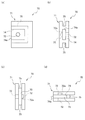
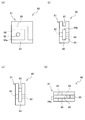
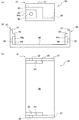
- FIG. 1 It is the front view (a) and the side view (b) of the fixing member 70 part provided in the support bracket of the outdoor unit which is Example 1 of this invention.
- (A) is a front view of a fixing member
- (b) is a left side view of (a)
- (c) is a right side view
- (d) is a top view of the outdoor unit that is Embodiment 1 of the present invention. It is. It is an exploded assembly figure of the attachment structure of the fixing member to the to-be-supported part which is Example 1 of this invention.
- (A) is a front view of a fixing member
- (b) is a left side view of (a)
- (c) is a right side view of the outdoor unit that is a modified example of Embodiment 1 of the present invention
- (d) is a side view of the same. It is the same top view.
- (A) is a front view of a fixing member
- (b) is a left side view of (a)
- (c) is a right side view
- (d) is a top view of an outdoor unit that is Embodiment 2 of the present invention. It is. It is an exploded assembly figure of the attachment structure of the fixing member to the to-be-supported part which is Example 2 of this invention.
- (A) of the outdoor unit which is Example 2 of this invention is a top view of the lower end part of a support bracket when a fixing member is attached to a supported part, and (b) is the right side view thereof.
- (A) of the outdoor unit which is Example 3 of this invention is a top view of the lower end part of a support bracket when a fixing member is attached to a supported part, (b) is the right side view.
- (A) of the outdoor unit which is Example 3 of this invention is a front view of the 1st fixing
- (A) is the front view of the 1st fixing
- FIG. 1 is a refrigeration cycle system diagram showing a refrigeration cycle apparatus 100 of the present embodiment, which includes an outdoor unit 1 and an indoor unit 2, and the outdoor unit 1 and the indoor unit 2 are refrigerant pipes (liquid side connection pipe 3 and gas side). Connected by connecting pipe 4).
- the outdoor unit 1 is provided with an accumulator 5, a compressor 6, a four-way valve 7, an outdoor heat exchanger 8, a first expansion valve 9, and the like. Further, a liquid blocking valve 10 connected to the liquid side connecting pipe 3 and a gas blocking valve 11 connected to the gas side connecting pipe 4 are provided.
- the indoor unit 2 is provided with an indoor heat exchanger 12 and a second expansion valve 13.
- the refrigeration cycle apparatus 100 operates as follows when performing a cooling operation.
- the high-temperature and high-pressure gas refrigerant compressed by the compressor 6 is discharged from the compressor 6 together with the refrigerating machine oil, and then flows into the outdoor heat exchanger 8 through the four-way valve 7 where heat exchange with outdoor air or the like is performed.
- the condensed and liquefied refrigerant passes through the fully opened first expansion valve 9 and is sent to the indoor unit 2 through the liquid blocking valve 10 and the liquid side connection pipe 3.
- the liquid refrigerant that has flowed into the indoor unit 2 is decompressed and expanded by the second expansion valve 13, becomes a low-temperature / low-pressure gas-liquid two-phase flow, enters the indoor heat exchanger 12, where indoor air or the like
- the user-side medium is cooled by exchanging heat with the user-side medium, and evaporates itself.
- the gas refrigerant forms a refrigeration cycle in which the gas refrigerant passes through the gas side connection pipe 4 and returns to the compressor 6 through the gas blocking valve 11, the four-way valve 7 and the accumulator 5.
- the surplus refrigerant in the refrigeration cycle is stored in the accumulator 5 so that the operating pressure and temperature of the refrigeration cycle are maintained in a normal state.
- the refrigeration cycle apparatus 100 operates as follows when performing a heating operation.
- the high-temperature and high-pressure gas refrigerant compressed by the compressor 6 is discharged from the compressor 6 together with the refrigerating machine oil, and passes through the four-way valve 7, the gas blocking valve 11, and the gas side connection pipe 4 to the indoor side heat exchanger 12 of the indoor unit 2. It flows in, and heat-exchanges with utilization side media, such as room air here, heats a utilization side medium, and self-condenses.
- the condensed and liquefied refrigerant is reduced in pressure by the first expansion valve 9 through the liquid side connection pipe 3 and the liquid blocking valve 10, and is evaporated and evaporated by exchanging heat with a heat source medium such as outdoor air in the outdoor heat exchanger 8. .
- the evaporated and evaporated refrigerant constitutes a refrigeration cycle in which the refrigerant returns to the compressor 6 through the four-way valve 7 and the accumulator 5.
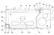
- FIG. 2 is a plan view showing the inside of the outdoor unit 1 with the top plate removed.
- the casing 20 of the outdoor unit 1 includes a top plate (not shown), a bottom plate 21, and side plates 22 to 25, and its internal space is partitioned into a heat exchange chamber 31 and a machine chamber 32 by a partition plate 26.
- An outdoor heat exchanger 8 and a blower 30 are disposed in the heat exchange chamber 31, and an accumulator 5, a compressor 6, and the like are disposed in the machine chamber 32.
- the side plates 22 to 25 are a machine room side front plate 22, a machine room side rear plate 23, a heat exchange chamber side front plate 24, and a heat exchange chamber side rear plate 25.
- the machine room 32 includes a machine room side front plate 22, a machine room side rear plate 23, and a partition plate 26.
- the heat exchange chamber 31 includes a heat exchange chamber side front plate 24 and a heat exchange chamber side rear plate 25, and further, between the machine room side rear plate 23 and the heat exchange chamber side rear plate 25, and the heat exchange chamber.
- Intake ports 27 and 28 provided between the side front plate 24 and the heat exchange chamber side rear plate 25 are provided.
- the intake ports 27 and 28 are air intake ports.
- the heat exchange chamber side front plate 24 is provided with an exhaust port 29 for exhausting the air heat-exchanged by the outdoor heat exchanger 8 from the front surface of the outdoor unit 1.
- the air sucked from the air inlets 27 and 28 provided on the back and side surfaces of the outdoor unit 1 by the blower 30 is heat-exchanged by the outdoor heat exchanger 8 and then provided on the front surface of the outdoor unit. It can be discharged out of the outdoor unit 1 through the exhaust port 29.
- the outdoor heat exchanger 8 in the refrigeration cycle apparatus (air conditioner) 100 shown in FIGS. 1 and 2 includes two header collecting pipes 41 made of aluminum (hereinafter, including an aluminum alloy), A plurality of flat heat transfer tubes 43 made of aluminum, arranged in the vertical direction between the header collecting pipes 42, one end connected to one header collecting pipe 41 and the other end connected to the other header collecting pipe 42; It is composed of a plurality of aluminum fins 44 joined to the flat heat transfer tube 43.
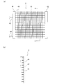
- FIG. 3A is a front view of the outdoor heat exchanger 8.
- the outdoor heat exchanger 8 includes a header collecting pipe 41, a header collecting pipe 42, a plurality of flat heat transfer tubes 43, and a plurality of fins 44, all of which are made of aluminum. And are joined to each other by brazing (the bending of the outdoor heat exchanger 8 in FIG. 2 is ignored).
- the header collecting pipe 41 and the header collecting pipe 42 are formed in an elongated cylindrical shape whose both ends are closed, and are arranged at a predetermined interval so that the longitudinal direction is a vertical direction.
- the header collecting pipe 41 is connected to an aluminum gas pipe 45 serving as a gas refrigerant inlet / outlet and an aluminum liquid pipe 46 serving as a liquid refrigerant inlet / outlet.
- the flat heat transfer tube 43 has an oval shape with a flat cross section in the short direction, and a plurality of refrigerant channels 47 are formed therein.
- the plurality of flat heat transfer tubes 43 are arranged in the vertical direction so as to be parallel to each other at a constant interval with the long side surfaces facing each other.
- the plurality of flat heat transfer tubes 43 have one end connected to the header collecting tube 41 and the other end connected to the header collecting tube 42, and the refrigerant flow passages inside the header collecting tube 41 are connected to the header collecting tube 41 and the header collecting tube 42. Communicate.
- the fin 44 has a vertically long plate shape in which a cut is formed by pressing, and the outdoor heat exchanger 8 has a structure in which the flat heat transfer tube 43 is inserted into the fin 44.
- An interval between adjacent fins 44 that is, a so-called fin pitch is, for example, about 1.5 mm.
- the interval between the header collecting pipe 41 or 42 and the outermost fin 44 adjacent to the header collecting pipe 41 or 42 is, for example, about 20 mm, which is 10 times or more the fin pitch. For this reason, air is more likely to flow around the header collecting pipes 41 and 42 and the sections between the header collecting pipes 41 and 42 and the outermost fins 44 than between the fins 44 and 44.
- a support bracket 51 (see FIGS. 2 and 4) is provided between the header collecting pipe 41 and the outer fin 44 nearest to the header collecting pipe 41 to block the air flow.
- a support bracket 52 (FIG. 2) is provided between the header collecting pipe 42 and the outer fin 44 nearest to the header collecting pipe 42 to block the air flow.
- support brackets 51 and 52 for blocking air flow around the header collecting pipes 41 and 42 and in a section between each of the header collecting pipes 41 and 42 and the outermost fin 44 will be described (representative). Then, the example of the support bracket 51 will be mainly described).
- the support bracket 51 (see FIGS. 2 and 4) and the support bracket 52 (see FIG. 2) have the same structure.
- FIG. 4 is a perspective view of the vicinity of the header collecting pipe 41 on the machine room 32 side
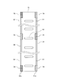
- FIG. 5 is a front view of the support bracket 51.
- the support bracket 51 is formed with a hole 63 through which the flat heat transfer tube 43 passes (see FIG. 5), and is arranged close to the fin 44 side between the header collecting tube 41 and the fin 44.
- the support bracket 51 includes supported portions 61 and 62, and the cross-sectional shape in the short direction of the support bracket 51 including the supported portions 61 and 62 is U-shaped so as to sandwich the flat heat transfer tube 43. I am doing. Of course, it may be configured in various shapes such as a U shape and a V shape as long as the air flow can be blocked.
- the support bracket 51 is made of aluminum, and is joined to the flat heat transfer pipe 43 or the header collecting pipe 41 at the same time when the members of the outdoor heat exchanger 8 are joined by brazing.
- the supported portions 61 and 62 have fixing members 70 (described later) for fixing to the machine room side rear plate 23 (FIG. 2) and the partition plate 26 (FIG. 2) according to the height of the support bracket 51. A plurality are provided. Further, auxiliary members 39 are provided between the fixing members 70 arranged in the vertical direction.
- the supported portion 61 of the support bracket 51 located on the upstream side of the air flowing through the outdoor heat exchanger 8 is connected to the machine room side rear plate 23 of the housing 20.
- the supported portion 62 that is fixedly supported and located on the downstream side is fixedly supported by the partition plate 26.
- the supported portion 64 on the upstream side of the air flowing through the outdoor heat exchanger 8 of the support bracket 52 (which has the same configuration as the support bracket 51) is used for heat exchange of the housing 20.
- the chamber side front plate 24 and the downstream supported portion 65 are fixed to the windproof plate 35, respectively.
- the support brackets 51 and 52 serve to block the passage of air in a portion where the fins 44 of the outdoor heat exchanger 8 are not attached (thereby improving the heat exchange efficiency of the outdoor heat exchanger 8). ) And the role of fixing the outdoor heat exchanger 8 to the casing 20 of the outdoor unit 1 can be combined with each other, so that the number of parts can be reduced.
- the support bracket 52 on the side of the heat exchange chamber 31 (which includes the supported portions 64 and 65 and has the same configuration as the support bracket 51) includes means that can suppress the same corrosion as the support bracket 51.
- the support bracket 51 will be described as a representative.
- the fixing member 70 that realizes means for suppressing such corrosion, and the fixing member 70 will be described in detail below.
- the fixing member 70 is provided, for example, at each leg portion, top portion, and intermediate position of the supported portions 61 and 62.
- the fixing member 70 includes an insulating portion made of an insulating material (for example, a resin material), and serves as a fixing position for fixing the support bracket 51 to the housing 20.
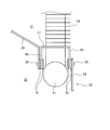
- FIG. 6 is a main part plan view showing a fixing part between the support bracket 51 and the housing 20.
- the supported portion 61 on the upstream side of the air and the machine room side rear plate 23 of the housing 20 are fixed by a screw 38 via a fixing member 70.
- the downstream supported portion 62 and the partition plate 26 are fixed by a screw 38 via a fixing member 70.
- FIG. 7A is a front view of the fixing member 70 provided on the support bracket 51
- FIG. 7B is a side view thereof.
- 8 (a) is a front view of the fixing member 70
- FIG. 8 (b) is a left side view of FIG. 8 (a)
- FIG. 8 (c) is a right side view thereof
- FIG. 9 is an exploded view of the structure for attaching the fixing member 70 to the supported portion 61.
- the fixing member 70 is, for example, a rectangular plate-like member when viewed from the front, and functions as an insulating part formed of an insulating material such as resin.
- 71 is provided.
- the first fixing portion 71 is formed with a concave groove 75 having a concave central portion of the plate thickness on its upper surface, right side surface, and lower surface.
- a rectangular pocket-shaped concave portion 74 is formed further inside the concave groove 75 with the left side surface as an opening 74a.
- the screw hole 72 penetrates from the front surface to the back surface of the first fixing portion 71 corresponding to the position where the concave portion 74 exists.
- the concave portion 74 has a rectangular plate shape corresponding to the rectangular pocket shape, and a metal, for example, a second fixing portion 36 made of steel is accommodated from the opening 74a.
- a metal for example, a second fixing portion 36 made of steel is accommodated from the opening 74a.
- the second fixing portion 36 is stored in the recess 74, the screw hole 72 and the screw hole 37 are aligned with each other.
- the fixing member 70 is attached to the supported portion 61 (the same applies to the supported portion 62)
- the second fixing portion 36 is accommodated in the concave portion 74 of the first fixing portion 71 to complete the fixing member 70 (in advance). Completed and prepared).
- a rectangular notch 66 is formed on the distal end side of the supported portion 61, and the shape of the inner peripheral edge of the notch 66 is the shape of the concave groove 75.
- the fixing member 70 can be attached to the supported portion 61 by engaging the groove 75 with the inner peripheral edge of the notch 66.
- the mounting position of the fixing member 70 to the supported portion 61 is a position where the machine room side rear plate 23 and the partition plate 26 are screwed and fixed (screw holes are formed in the machine room side rear plate 23 and the partition plate 26). It is.
- the shape of the fixing member 70 is not limited to a rectangular shape, and may be various shapes. The same applies to the shapes of the concave groove 75 of the fixing member 70 and the second fixing portion 36 (concave portion 74).
- the fixing members 70 are provided at a plurality of positions in the height direction of the supported portions 61 and 62. As shown in FIGS. 7 and 5, between the upper and lower fixing members 70, 70, the fixing member 70 extending to the side portion of the supported portions 61, 62 and the auxiliary member projecting in the same direction on the outside. 39 is provided.
- the auxiliary member 39 is made of resin or other insulating material, and is provided by bonding or other means. It is desirable that the auxiliary member 39 projects to the side of the supported portions 61 and 62 to the same extent as the fixing member 70. Alternatively, the auxiliary member 39 may form part of the supported portions 61 and 62.
- the fixing member 70 includes the insulating portion (first fixing portion 71) that insulates the support bracket 51 and the casing 20 of the outdoor unit 1, and the fixing member 70 is connected to the casing 20. Therefore, the support bracket 51 can be prevented from being corroded.
- the fixing member 70 includes a second fixing portion 36, and the second fixing portion 36 fixes the support bracket 51 to the housing 20 by screwing. And even if it fixes by screwing, since the 2nd fixing
- the fixing member 70 is attached to the notch 66 of the supported portions 61 and 62, it is possible to prevent the fixing member 70 from protruding so much from the supported portions 61 and 62, and the housing 20 of the support bracket 51.
- the mounting structure can be made compact. Since the auxiliary member 39 is provided in the supported portions 61 and 62, it is difficult to form a gap between the fixing members 70 and 70, and air is prevented from entering the support bracket 51, so that the heat of the outdoor heat exchanger 8 can be reduced. Exchange efficiency can be improved.
- FIG. 10 (a) is a front view of the fixing member 70
- FIG. 10 (b) is a left side view of FIG. 10 (a)
- FIG. 10 (c) is a right side view thereof
- FIG. 10 (d) is a top view thereof. is there.
- This modification is different from the first embodiment in that the screw hole 72 formed in the first fixing portion 71 does not penetrate the fixing member 70, and the tip of the screw 38 (FIG. 6) is in the middle of the fixing member 70. Is to stay on. In the example of FIG. 10, the tip end portion 72 a of the screw hole 72 remains in the middle of the first fixing portion 71. In addition, you may make it the screw hole 72 stay in the 2nd fixing
- the screw hole 72 does not penetrate the fixing member 70 and the tip of the screw 38 (FIG. 6) stays inside the fixing member 70, so that the fixing member 70 is fixed when screwed to the housing 20.
- Iron powder generated from the second fixing portion 36 (FIG. 9) and the screw 38 (FIG. 6) does not jump out of the member 70. Since these iron powder falls on the support bracket 51 and causes corrosion, the support bracket 51 can be prevented from being corroded.
- Example 2 Example 2 will be described.
- the same reference numerals are used for members and the like that are the same as those in Embodiment 1, and detailed description thereof is omitted.
- the portions 61a and 62a of the supported portions 61 and 62 are exposed at the lowermost portion of the fixing member 70, and therefore the portion 61a is formed on the bottom portion (bottom plate 21) of the casing 20 of the outdoor unit 1.
- 62a come into contact with each other and cause corrosion of the support bracket 51.
- a fixing member 80 shown in FIG. 11 is used at the bottom of the support bracket 51 instead of the fixing member 70.
- FIG. 11 (a) is a front view of the fixing member 80
- FIG. 11 (b) is a left side view of FIG. 11 (a)
- FIG. 11 (c) is a right side view thereof
- FIG. 11 (d) is a top view thereof. is there.
- the fixing member 80 is a rectangular plate-like member as viewed from the front, and includes a first fixing portion 81 that functions as an insulating portion formed of an insulating material such as resin.
- the first fixing portion 81 is formed with a concave groove 85 having a concave central portion at the upper surface and right side.
- a rectangular pocket-shaped concave portion 84 is formed further inside the concave groove 85 with the left side surface as an opening 84a.
- the screw hole 82 penetrates from the front surface to the back surface of the first fixing portion 81 corresponding to the position where the concave portion 84 exists (it does not have to penetrate as in the modification of the first embodiment).
- the concave portion 84 has a rectangular plate shape corresponding to the rectangular pocket shape, and a metal, for example, a second fixing portion 36 (FIG. 9) made of steel is accommodated from the opening 84a.
- a screw hole 37 (FIG. 9) passes through, for example, the central portion of the second fixing portion 36, and when the second fixing portion 36 is stored in the recess 84, the screw hole 82 and the screw hole 37 (FIG. 9). The position is correct.
- the fixing member 80 is different from the fixing member 70 in that the concave groove 85 is not formed on the lower side of the first fixing portion 81, and the entire bottom portion of the fixing member 80 covers a part of the first fixing portion 81.
- the bottom part 83 is formed.
- FIG. 13A is a plan view of a lower end portion of the support bracket 51 when the fixing member 80 is attached to the supported portions 61 and 62
- FIG. 13B is a right side view thereof.
- the lower end portion of the support bracket is in contact with the housing 20 of the outdoor unit 1 through the bottom 83 of the fixing member 80, so that the support bracket 51 is not easily corroded.
- the support bracket 51 is raised by the amount corresponding to the bottom portion 83, and as shown in FIG. Therefore, it is desirable to provide a spacer or the like in the space 89 to close the space 89 and increase the heat exchange efficiency of the outdoor heat exchanger 8.
- Example 3 Example 3 will be described.
- the same reference numerals are used for members and the like that are the same as those in Embodiment 1, and detailed description thereof is omitted.
- This embodiment is different from the first and second embodiments in that the fixing member 90 used in place of the fixing member 70 is attached to the lower ends of both the supported portion 61 and the supported portion 62 as a single unit.
- FIG. 14A is a plan view of the lower end portion of the support bracket 51 when the fixing member 90 is attached to the supported portions 61 and 62
- FIG. 14B is a right side view thereof.
- FIG. 15A is a front view of the first fixing portion 91 in the fixing member 90
- FIG. 15B is a left side view of FIG. 15A
- FIG. 15C is a top view thereof.
- the fixing member 90 has a first fixing portion 91 that functions as an insulating portion.
- the first fixing portion 91 includes a bottom plate 96 having a width from the supported portions 61 to 62 including a storage portion 94 described later.
- Side plates 97 stand up from both sides of the bottom plate 96.
- a storage portion 94 that stores the second fixing portion 36 (FIG. 12) is formed on the inner surface of the side plate 97.
- the upper outer shape of the L-shaped convex member 95 (projecting inside the first fixing portion 91) that forms the storage portion 94 and protrudes from the side plate 97 into the fixing member 90 is a notch 67 (FIG. 12). Align with the edge of the.
- the storage portion 94 is not pocket-shaped and there is no wall inside the fixing member 90.
- the inlet 94a serves as an inlet for housing the second fixing portion 36 (FIG. 12).
- the second fixing portion 36 (FIG. 12) is supported on the inner periphery of the convex member 95.
- a screw hole 92 is formed in each side plate 97. The screw hole 92 is aligned with the screw hole 37 when the second fixing portion 36 (FIG.
- the screw hole 92 may exist partway through the second fixing portion 36 and may not penetrate the first fixing portion 91 and the second fixing portion 36. Note that the screw 38 (FIG. 6) passes through the notch 67 and does not contact the supported portions 61 and 62.
- the second fixing portion 36 (FIG. 12) is attached to the first fixing portion 91, the lower end side of the support bracket 51 is inserted into the first fixing portion 91, and the notches 67 of the supported portions 61 and 62 are inserted.
- the fixing member 90 can be attached to the support bracket 51 by supporting (FIG. 12) with the upper outer shape of the convex member 95. As a result, the fixing member 90 covers the entire bottom surface of the support bracket 51.
- the fixing member 90 is not configured to be sandwiched between the first fixing portion 91 from both sides of the supported portion 61 and the supported portion 62, but the supported portion 61 and the supported portion 62.
- a side plate 97 projects from the outside of each.
- the bottom plate 96 that forms a part of the first fixing portion 91 can be brought into contact with the casing 20 of the outdoor unit 1, corrosion of the support bracket 51 can be prevented. Furthermore, compared with the case of Example 1, 2, the stability at the time of installing the outdoor side heat exchanger 8 increases by the contact area of the bottom face with the support bracket 51, and the fixing member 90 increasing. In addition, by adopting a structure that covers the entire bottom surface of the support bracket 51, the gap between the support bracket 51 and the fixing member 90 disappears, and air can be prevented from entering the inside of the support bracket 51.
- FIG. 16 (a) is a front view of the first fixing portion 91 of the fixing member 90
- FIG. 16 (b) is a left side view of FIG. 16 (a)
- FIG. 16 (c) is a top view thereof.
- This modification is different from the third embodiment in that the flat portion 93 for supporting the entire bottom surface of the support bracket 51 on the top surface of the bottom plate 96 is the same as the bottom surface of the support bracket 51 as shown in FIG.
- the inside of the flat surface portion 93 forms an inclined surface 98 that is inclined downward toward the U-shaped open portion (outside of the support bracket 51).
- the inclined surface 98 which inclines downward toward the outer side of the support bracket 51 is provided on the upper surface of the bottom plate 96, rainwater or the like is unlikely to collect on the bottom plate 96, and the support bracket 51 is hardly corroded. Can do.
- this invention is not limited to an above-described Example, Various modifications are included.
- the above-described embodiments have been described in detail for easy understanding of the present invention, and are not necessarily limited to those having all the configurations described.
- a part of the configuration of one embodiment can be replaced with the configuration of another embodiment, and the configuration of another embodiment can be added to the configuration of one embodiment.
- the support bracket 51 two supported portions 61 and 62 are provided, but three or more supported portions may be provided, or only one may be provided.
- screwing is used to attach the support bracket 51 to the housing 20 of the outdoor unit 1, other attachment means may be used.
- the auxiliary member 39 may be provided on both sides of the supported portions 61 and 62.
Landscapes
- Engineering & Computer Science (AREA)
- Mechanical Engineering (AREA)
- General Engineering & Computer Science (AREA)
- Physics & Mathematics (AREA)
- Thermal Sciences (AREA)
- Chemical & Material Sciences (AREA)
- Combustion & Propulsion (AREA)
- Other Air-Conditioning Systems (AREA)
- Details Of Heat-Exchange And Heat-Transfer (AREA)
Abstract
複数本が並ぶ扁平伝熱管(43)と、扁平伝熱管(43)の管方向に並んで複数本の扁平伝熱管(43)に複数枚設けられるフィン(44)と、各扁平伝熱管(43)の両端にそれぞれ接続されるヘッダ集合管(41),(42)と、扁平伝熱管(43)方向の最も外側のフィン(44)とヘッダ集合管(41),(42)との間にフィン(44)の存在しない空間の空気の通過を遮るように設けられ、筐体に固定されて扁平伝熱管(43)およびフィン(44)を支持する支持ブラケット(51)と、支持ブラケット(51)に取り付けられ、支持ブラケット(51)と筐体とを絶縁する部材を備え、支持ブラケット(51)を筐体に固定するための固定位置となる固定部材(70)とを備える。
Description
本発明は、室外機および冷凍サイクル装置に関する。
本技術分野の背景技術として、特許第5403085号公報(特許文献1)がある。この公報には、「複数のヘッダ集合管(34,35)、複数の前記ヘッダ集合管の間に所定のフィンピッチで配置されている複数のフィン(32)及び複数の前記フィンに挿通されて複数の前記ヘッダ集合管に接続されている複数の伝熱管(33)を有し、互いに隣り合う前記ヘッダ集合管と前記フィン(32p,32q)との間に前記フィンピッチよりも大きな隙間(IS1,IS2)が形成されている熱交換器(13)と、複数の前記ヘッダ集合管のうちの少なくとも一つに対面して配置され、前記熱交換器の一部を囲うためのケーシング構成部材と、前記ケーシング構成部材に取り付けられ、前記ケーシング構成部材に対面する前記隙間の周囲の前記ヘッダ集合管と前記フィンとに押し付けられて変形し、前記隙間を塞ぐシール部材(51,52,53,54)と、を備え、前記ケーシング構成部材は、前記熱交換器の風上側に配置されている第1ケーシング構成部材(25,24)を含み、前記シール部材は、前記第1ケーシング構成部材に取り付けられ、前記隙間の風上側に配置されている第1シール部材(51,53)を含む、冷凍装置の室外ユニット」と記載されている(請求項1参照)。
前記特許文献1には、第1シール部材が記載されている。第1シール部材はフィンを通過しない空気を抑制する働きをする。しかし、特許文献1では、第1シール部材で熱交換器を室外機の筐体に支持し、固定することは考慮されていない。
そこで、本発明は、伝熱管やフィンを支持しフィンを通過しない空気を阻止する支持ブラケットを腐食させることなく筐体に固定できる室外機を提供することを課題とする。
そこで、本発明は、伝熱管やフィンを支持しフィンを通過しない空気を阻止する支持ブラケットを腐食させることなく筐体に固定できる室外機を提供することを課題とする。
上記課題を解決するため、本発明の一形態は、筐体と、複数本が並ぶ伝熱管と、前記伝熱管の管方向に並んで前記複数本の伝熱管に複数枚設けられるフィンと、前記各伝熱管の両端にそれぞれ接続されるヘッダ集合管と、前記伝熱管の管方向の最も外側の前記フィンと前記ヘッダ集合管との間に前記フィンの存在しない空間の空気の通過を遮るように設けられ、前記筐体に固定されて前記伝熱管および前記フィンを支持する支持ブラケットと、前記支持ブラケットに取り付けられ、前記支持ブラケットを前記筐体に固定するための固定位置となる固定部材とを備え、前記固定部材は、前記支持ブラケットと前記筐体とを絶縁する絶縁部を有していることを特徴とする。
本発明によれば、支持ブラケットを腐食させることなく筐体に固定できる室外機を提供することができる。
上記した以外の課題、構成および効果は、以下の実施形態の説明により明らかにされる。
上記した以外の課題、構成および効果は、以下の実施形態の説明により明らかにされる。
以下、本発明の実施例について図面を用いて説明する。
[実施例1]
図1は本実施例の冷凍サイクル装置100を示す冷凍サイクル系統図であり、室外機1と室内機2とを備え、室外機1と室内機2は冷媒配管(液側接続配管3とガス側接続配管4)により接続されている。
室外機1には、アキュムレータ5、圧縮機6、四方弁7、室外側熱交換器8および第1の膨張弁9などが設けられている。また、液側接続配管3と接続される液阻止弁10およびガス側接続配管4と接続されるガス阻止弁11が設けられている。
室内機2には、室内側熱交換器12および第2の膨張弁13などが設けられている。
図1は本実施例の冷凍サイクル装置100を示す冷凍サイクル系統図であり、室外機1と室内機2とを備え、室外機1と室内機2は冷媒配管(液側接続配管3とガス側接続配管4)により接続されている。
室外機1には、アキュムレータ5、圧縮機6、四方弁7、室外側熱交換器8および第1の膨張弁9などが設けられている。また、液側接続配管3と接続される液阻止弁10およびガス側接続配管4と接続されるガス阻止弁11が設けられている。
室内機2には、室内側熱交換器12および第2の膨張弁13などが設けられている。
冷凍サイクル装置100は、冷房運転を行う場合には次のように動作する。圧縮機6で圧縮された高温高圧のガス冷媒は冷凍機油とともに圧縮機6から吐出され、その後、四方弁7を経て、室外側熱交換器8へと流入し、ここで室外空気等と熱交換して凝縮液化する。凝縮液化した冷媒は全開とされた第1の膨張弁9を通り、液阻止弁10および液側接続配管3を経て、室内機2へ送られる。室内機2に流入した液冷媒は、第2の膨張弁13で減圧されて膨張し、低温・低圧の気液二相流となって、室内側熱交換器12に入り、ここで室内空気等の利用側媒体と熱交換して利用側媒体を冷却するとともに、自らは蒸発気化する。その後、ガス冷媒はガス側接続配管4を通り、ガス阻止弁11、四方弁7、アキュムレータ5を経て圧縮機6へ戻るという冷凍サイクルを構成する。冷凍サイクルの余剰冷媒はアキュムレータ5に貯留され、冷凍サイクルの運転圧力、温度が正常な状態に保たれるように構成されている。
冷凍サイクル装置100は、暖房運転を行う場合には次のように動作する。圧縮機6で圧縮された高温高圧のガス冷媒は冷凍機油とともに圧縮機6から吐出され、四方弁7、ガス阻止弁11、ガス側接続配管4を経て室内機2の室内側熱交換器12へ流入し、ここで室内空気等の利用側媒体と熱交換して利用側媒体を加熱し、自らは凝縮液化する。凝縮液化した冷媒は、液側接続配管3、液阻止弁10を経て、第1の膨張弁9で減圧され、室外側熱交換器8で室外空気等の熱源媒体と熱交換して蒸発気化する。蒸発気化した冷媒は四方弁7、アキュムレータ5を経て圧縮機6へ戻るという冷凍サイクルを構成する。
図1に示す室外機1を構成している室外側熱交換器8などは、通常、筐体内部に設置されている。図2は、天板を外した状態の室外機1の内部を示す平面図である。室外機1の筐体20は、天板(図示せず)と、底板21と、側板22~25を備えており、その内部空間は仕切り板26により、熱交換室31と機械室32に区画されている。熱交換室31には室外側熱交換器8と送風機30が配置され、機械室32にはアキュムレータ5や圧縮機6などが配置されている。側板22~25は、機械室側前側板22、機械室側後側板23、熱交換室側前側板24および熱交換室側後側板25である。機械室32は機械室側前側板22、機械室側後側板23および仕切り板26で構成されている。一方、熱交換室31は、熱交換室側前側板24と熱交換室側後側板25とを備え、さらに、機械室側後側板23と熱交換室側後側板25の間、および熱交換室側前側板24と熱交換室側後側板25の間にそれぞれ設けた吸気口27,28を備えている。吸気口27,28は空気の吸い込み口である。さらに、熱交換室側前側板24には、室外側熱交換器8により熱交換された空気を室外機1の前面から排出させるための排気口29が設けられている。このような構造により、送風機30によって、室外機1の背面および側面に設けられた吸気口27,28から吸い込んだ空気を室外側熱交換器8により熱交換した後、室外機前面に設けられた排気口29から室外機1の外に排出させることができる。
図1および図2に示す冷凍サイクル装置(空気調和機)100における室外側熱交換器8は、本実施例では、アルミニウム(以下、アルミニウム合金を含む)製の2本のヘッダ集合管41と、ヘッダ集合管42との間に上下方向に配列され、一端が一方のヘッダ集合管41に連結され、他端が他方のヘッダ集合管42に連結されたアルミニウム製の複数の扁平伝熱管43と、扁平伝熱管43に接合されたアルミニウム製の複数のフィン44で構成されている。
この室外側熱交換器8の構成を図3により説明する。図3(a)は室外側熱交換器8の正面図である。
図3(a)に示すように、室外側熱交換器8は、ヘッダ集合管41と、ヘッダ集合管42と、複数の扁平伝熱管43と複数のフィン44を備えており、何れもアルミニウム製の部材であって、お互いにロウ付けにより接合されている(図2の室外側熱交換器8の屈曲は無視して図示している)。
ヘッダ集合管41とヘッダ集合管42は、両端が閉塞された細長い円筒状に形成されており、長手方向が垂直方向になるように所定間隔をあけて配置されている。ヘッダ集合管41には、ガス冷媒の出入り口となるアルミニウム製のガス管45と液冷媒の出入り口となるアルミニウム製の液管46とが接続されている。
図3(a)に示すように、室外側熱交換器8は、ヘッダ集合管41と、ヘッダ集合管42と、複数の扁平伝熱管43と複数のフィン44を備えており、何れもアルミニウム製の部材であって、お互いにロウ付けにより接合されている(図2の室外側熱交換器8の屈曲は無視して図示している)。
ヘッダ集合管41とヘッダ集合管42は、両端が閉塞された細長い円筒状に形成されており、長手方向が垂直方向になるように所定間隔をあけて配置されている。ヘッダ集合管41には、ガス冷媒の出入り口となるアルミニウム製のガス管45と液冷媒の出入り口となるアルミニウム製の液管46とが接続されている。
扁平伝熱管43は、図3(b)に示すように、その短手方向断面が扁平な長円形状であり、内部に複数の冷媒流路47が形成されている。複数の扁平伝熱管43は、それぞれ長辺面が対抗する状態で、互いに一定の間隔をおいて平行になるように上下方向に配列されている。複数の扁平伝熱管43は、一端がヘッダ集合管41に接続され、かつ他端がヘッダ集合管42に接続されており、その内部の冷媒流路が、ヘッダ集合管41およびヘッダ集合管42と連通している。
フィン44はプレス加工により切り込みを形成した縦長のプレート形状で、室外側熱交換器8はフィン44に扁平伝熱管43を差し込んだ構造となっている。隣り合うフィン44同士の間隔、いわゆるフィンピッチは例えば1.5mm程度である。これに対し、ヘッダ集合管41または42と、それと隣り合う最も外側のフィン44の間隔は、例えば20mm程度であり、フィンピッチの10倍以上にもなってしまう。そのため、空気はフィン44とフィン44との間に比べて、ヘッダ集合管41,42周囲や、ヘッダ集合管41,42それぞれと最も外側のフィン44との間の区間の方に流れやすくなる。
ヘッダ集合管41とそれに最も近い外側のフィン44との間には空気の流れを遮断するための支持ブラケット51(図2、図4参照)が設けられている。同様に、ヘッダ集合管42とそれに最も近い外側のフィン44との間には空気の流れを遮断するための支持ブラケット52(図2)が設けられている。以下、ヘッダ集合管41,42の周囲や、ヘッダ集合管41,42それぞれと最も外側のフィン44との間の区間において、空気の流れを遮断するための支持ブラケット51,52について説明する(代表して支持ブラケット51の例を中心に説明する)。支持ブラケット51(図2、図4参照)と支持ブラケット52(図2参照)は同じ構造になっている。図4は機械室32側におけるヘッダ集合管41近傍の斜視図で、図5は支持ブラケット51の正面図である。支持ブラケット51は、扁平伝熱管43を通すための穴63が形成されており(図5参照)、ヘッダ集合管41とフィン44との間でフィン44側に寄せて配置されている。また支持ブラケット51は、被支持部61,62を具備しており、被支持部61,62を含む支持ブラケット51の短手方向の断面形状は、扁平伝熱管43を挟み込むようにコの字型をしている。もちろん、空気の流れを遮断できるのであれば、U字形、V字形など様々な形状に構成してよい。支持ブラケット51はアルミニウム製であり、室外側熱交換器8の各部材をロウ付けで接合する際に同時に扁平伝熱管43、またはヘッダ集合管41と接合されている。被支持部61,62には、それぞれ機械室側後側板23(図2)および仕切り板26(図2)と固定するための固定部材70(後記)が、支持ブラケット51の高さに応じて複数個設けられている。さらに、上下方向に並ぶ各固定部材70の間には、補助部材39が設けられている。
機械室32側では、図2に示すように、支持ブラケット51の、室外側熱交換器8を流れる空気の上流側に位置する被支持部61は、筐体20の機械室側後側板23に固定支持され、下流側に位置する被支持部62は仕切り板26に固定支持されている。
さらに、熱交換室31側においても、支持ブラケット52(支持ブラケット51と同様の構成である)の、室外側熱交換器8を流れる空気の上流側の被支持部64は筐体20の熱交換室側前側板24と、下流側の被支持部65は防風板35とそれぞれ固定されている。
さらに、熱交換室31側においても、支持ブラケット52(支持ブラケット51と同様の構成である)の、室外側熱交換器8を流れる空気の上流側の被支持部64は筐体20の熱交換室側前側板24と、下流側の被支持部65は防風板35とそれぞれ固定されている。
このように、支持ブラケット51,52は、室外側熱交換器8のフィン44が取り付けられていない部位の空気の通過を遮断する役割(それにより室外側熱交換器8の熱交換効率を向上する)と、室外側熱交換器8を室外機1の筐体20に固定する役割とを一部品でそれぞれ兼用していて、部品点数の削減を図ることができる。
しかしながら、支持ブラケット51,52はアルミニウム製であり、室外機1の鋼製等の筐体20と絶縁されていないと、腐食が進みやすいという不具合がある。
そこで、以下では、支持ブラケット51,52の腐食を抑制できる手段について説明する。
なお、熱交換室31側における支持ブラケット52(被支持部64,65を備えており、前記支持ブラケット51と同様の構成である)に関しても、支持ブラケット51と同様の腐食を抑制できる手段を備えていることが望ましいが、以下では、代表して支持ブラケット51について説明する。
そこで、以下では、支持ブラケット51,52の腐食を抑制できる手段について説明する。
なお、熱交換室31側における支持ブラケット52(被支持部64,65を備えており、前記支持ブラケット51と同様の構成である)に関しても、支持ブラケット51と同様の腐食を抑制できる手段を備えていることが望ましいが、以下では、代表して支持ブラケット51について説明する。
かかる腐食を抑制する手段を実現しているのは固定部材70であり、以下では固定部材70について詳細に説明する。固定部材70は、図5に示すように、例えば、被支持部61,62のそれぞれの脚部、頂部、中間位置に設けられている。固定部材70は、絶縁性の材料(例えば樹脂材料)で構成された絶縁部を備え、支持ブラケット51を筐体20に固定するための固定位置となる。
図6は、支持ブラケット51と筐体20との固定部を示す要部平面図である。同図に示すように、空気の上流側の被支持部61と筐体20の機械室側後側板23とは、固定部材70を介してねじ38により固定される。また、下流側の被支持部62と仕切り板26とは、固定部材70を介してねじ38により固定される。
図7(a)は、支持ブラケット51に設けられた固定部材70部分の正面図、図7(b)は、同側面図である。図8(a)は固定部材70の正面図、図8(b)は図8(a)の左側面図、図8(c)は同右側面図、図8(d)は同上面図である。図9は、被支持部61への固定部材70の取付構造の分解組み立て図である。
図7(a)は、支持ブラケット51に設けられた固定部材70部分の正面図、図7(b)は、同側面図である。図8(a)は固定部材70の正面図、図8(b)は図8(a)の左側面図、図8(c)は同右側面図、図8(d)は同上面図である。図9は、被支持部61への固定部材70の取付構造の分解組み立て図である。
主に図8(a)に示すように、固定部材70は、例えば正面から視て矩形状の板状部材であり、樹脂などの絶縁材料で形成された絶縁部として機能する第一の固定部71を備えている。第一の固定部71には、その上面、右側面、下面に板厚の中央部を凹形状とした凹溝75が形成されている。また、左側面を開口74aとして矩形ポケット状の凹部74が凹溝75のさらに内側に形成されている。さらに、凹部74の存在位置に対応して、第一の固定部71の正面から裏面にかけてねじ孔72が貫通している。
凹部74には、その矩形ポケット形状に対応した矩形板状であり、金属、例えば鋼製の第二の固定部36が開口74aから収納されている。第二の固定部36の例えば中央部にはねじ孔37が貫通していて、第二の固定部36を凹部74に収納した時は、ねじ孔72とねじ孔37の位置は合っている。
固定部材70を被支持部61(被支持部62も同様)へ装着するときは、第一の固定部71の凹部74に第二の固定部36を収納し、固定部材70を完成させる(予め完成させて用意しておく)。
固定部材70を被支持部61(被支持部62も同様)へ装着するときは、第一の固定部71の凹部74に第二の固定部36を収納し、固定部材70を完成させる(予め完成させて用意しておく)。
そして、図9に示すように、被支持部61の先端部側には矩形状の切欠き66が形成されていて、この切欠き66における内周の端縁部の形状は凹溝75の形状に合っている。そこで、この切欠き66の内周の端縁部に凹溝75を係合させることで、被支持部61に固定部材70を取り付けることができる。ねじ38(図6参照)で前記のとおりねじ留め固定するときは、ねじ38は切欠き66を挿通している。固定部材70の被支持部61への取り付け位置は、機械室側後側板23、仕切り板26とねじ留め固定する(機械室側後側板23、仕切り板26にねじ孔が形成されている)位置である。このように筐体20と被支持部61,62とをネジ留め固定したときは、第二の固定部36と、支持ブラケット51とは第一の固定部71によって絶縁されている。なお、固定部材70の形状は矩形状に限定されず、様々な形状としてよい。これは、固定部材70の凹溝75、第二の固定部36(凹部74)の形状においても同様である。
前記のとおり、被支持部61,62の高さ方向の複数個所に固定部材70が設けられている。そして、図7、図5に示すように、上下の固定部材70,70の間には、被支持部61,62の側部に延出する固定部材70と外側の同じ方向に張り出す補助部材39が設けられている。補助部材39は、樹脂、その他の絶縁性材料で形成されていて、接着その他の手段により設けられている。補助部材39は固定部材70と同程度、被支持部61,62の側部に張り出すのが望ましい。あるいは、補助部材39は被支持部61,62の一部をなしていてもよい。
以上説明した本実施形態によれば、固定部材70は支持ブラケット51と室外機1の筐体20とを絶縁する絶縁部(第一の固定部71)を備え、固定部材70が筐体20への固定位置となるので、支持ブラケット51を腐食させないようにすることができる。
固定部材70は第二の固定部36を備え、第二の固定部36で支持ブラケット51の筐体20へのねじ留め固定を行う。そして、ねじ留め固定しても第二の固定部36は支持ブラケット51に非接触であるため、支持ブラケット51を第二の固定部36により腐食させないようにすることができる。
固定部材70は第二の固定部36を備え、第二の固定部36で支持ブラケット51の筐体20へのねじ留め固定を行う。そして、ねじ留め固定しても第二の固定部36は支持ブラケット51に非接触であるため、支持ブラケット51を第二の固定部36により腐食させないようにすることができる。
固定部材70は被支持部61,62の切欠き66に装着するので、固定部材70が被支持部61,62からあまり張り出さないようにすることが可能であり、支持ブラケット51の筐体20への取付構造をコンパクト化することができる。
被支持部61,62に補助部材39を設けたので、固定部材70,70間に隙間ができにくく、支持ブラケット51内に空気が侵入するのを抑制して、室外側熱交換器8の熱交換効率を向上させることができる。
被支持部61,62に補助部材39を設けたので、固定部材70,70間に隙間ができにくく、支持ブラケット51内に空気が侵入するのを抑制して、室外側熱交換器8の熱交換効率を向上させることができる。
[実施例1の変形例]
本変形例において、前記の実施例1と共通の部材等には同一の符号を用い、詳細な説明は省略する。図10(a)は固定部材70の正面図、図10(b)は図10(a)の左側面図、図10(c)は同右側面図、図10(d)は同上面図である。本変形例が実施例1と異なるのは、第一の固定部71に形成されているねじ孔72が固定部材70を貫通せず、ねじ38(図6)の先端は固定部材70内部の途中にとどまることである。図10の例では、第一の固定部71の途中にねじ孔72の先端部72aがとどまっている。なお、第二の固定部36(図9)でねじ孔72がとどまるようにしても良い。
本変形例において、前記の実施例1と共通の部材等には同一の符号を用い、詳細な説明は省略する。図10(a)は固定部材70の正面図、図10(b)は図10(a)の左側面図、図10(c)は同右側面図、図10(d)は同上面図である。本変形例が実施例1と異なるのは、第一の固定部71に形成されているねじ孔72が固定部材70を貫通せず、ねじ38(図6)の先端は固定部材70内部の途中にとどまることである。図10の例では、第一の固定部71の途中にねじ孔72の先端部72aがとどまっている。なお、第二の固定部36(図9)でねじ孔72がとどまるようにしても良い。
このように、ねじ孔72が固定部材70を貫通せず、ねじ38(図6)の先端が固定部材70の内部にとどまることで、固定部材70を筐体20にねじ留めしたときに、固定部材70の内部から第二の固定部36(図9)やねじ38(図6)から発生した鉄粉が飛び出してこない。これらの鉄粉は、支持ブラケット51に落下して腐食の原因になるので、支持ブラケット51の腐食を防止することができる。
[実施例2]
実施例2について説明する。本実施例で実施例1と共通の部材等には同一の符号を用い、詳細な説明は省略する。
実施例1の図5の例では、固定部材70の最下部に被支持部61,62の部分61a,62aが露出するので、室外機1の筐体20の底部(底板21)に当該部分61a,62aが接触し、支持ブラケット51の腐食の原因となってしまう。それを防止するには、絶縁を防止する部材が余計に必要である。
そこで、支持ブラケット51の底部には固定部材70に代えて図11に示す固定部材80を使用する。図11(a)は固定部材80の正面図、図11(b)は図11(a)の左側面図、図11(c)は同右側面図、図11(d)は同上面図である。
実施例2について説明する。本実施例で実施例1と共通の部材等には同一の符号を用い、詳細な説明は省略する。
実施例1の図5の例では、固定部材70の最下部に被支持部61,62の部分61a,62aが露出するので、室外機1の筐体20の底部(底板21)に当該部分61a,62aが接触し、支持ブラケット51の腐食の原因となってしまう。それを防止するには、絶縁を防止する部材が余計に必要である。
そこで、支持ブラケット51の底部には固定部材70に代えて図11に示す固定部材80を使用する。図11(a)は固定部材80の正面図、図11(b)は図11(a)の左側面図、図11(c)は同右側面図、図11(d)は同上面図である。
固定部材80は、正面から視て矩形状の板状部材であり、樹脂などの絶縁材料で形成された絶縁部として機能する第一の固定部81を備えている。第一の固定部81には、その上面、右側面に板厚の中央部を凹形状とした凹溝85が形成されている。また、左側面を開口84aとして矩形ポケット状の凹部84が凹溝85のさらに内側に形成されている。さらに、凹部84の存在位置に対応して、第一の固定部81の正面から裏面にかけてねじ孔82が貫通している(実施例1の変形例のように貫通してなくてもよい)。
凹部84には、その矩形ポケット形状に対応した矩形板状であり、金属、例えば鋼製の第二の固定部36(図9)が開口84aから収納されている。第二の固定部36の例えば中央部にはねじ孔37(図9)が貫通していて、第二の固定部36を凹部84に収納した時はねじ孔82とねじ孔37(図9)の位置は合っている。
固定部材80が固定部材70と異なるのは、第一の固定部81の下側には凹溝85が形成されておらず、固定部材80の底部全体が第一の固定部81の一部をなす底部83をなしている点である。
固定部材80を被支持部61(被支持部62も同様)へ取り付けるときは、第一の固定部81の凹部84に第二の固定部36を収納し、固定部材80を完成させる(予め完成させて用意しておく)。
固定部材80を被支持部61(被支持部62も同様)へ取り付けるときは、第一の固定部81の凹部84に第二の固定部36を収納し、固定部材80を完成させる(予め完成させて用意しておく)。
被支持部61,62の最下端部には、図12に示すように矩形状の切欠き67が形成されていて、この切欠き67の内周の端縁部の形状は凹溝85の形状に合っている。そこで、この切欠き67の内周の端縁部に凹溝85を係合させることで、被支持部61,62に固定部材80を取り付けることができる。ねじ38(図6)で前記の固定部材70の場合と同様にねじ留め固定するときは、ねじ38は切欠き67を挿通している。
図13(a)は、固定部材80を被支持部61,62に取り付けたときにおける支持ブラケット51の下端部の平面図であり、図13(b)は、同右側面図である。
図13(a)は、固定部材80を被支持部61,62に取り付けたときにおける支持ブラケット51の下端部の平面図であり、図13(b)は、同右側面図である。
図13に明らかなように、支持ブラケットの下端部は固定部材80の底部83を介して室外機1の筐体20と接するので、支持ブラケット51は腐食しにくい。
このとき、底部83の分だけ、支持ブラケット51が高くなり、図13(a)に示すように支持ブラケット51の下に空間89が空き、空気の通り道となる。そこで、空間89にスペーサ等を設けて、当該空間89を塞ぎ、室外側熱交換器8の熱交換効率を高めるのが望ましい。
このとき、底部83の分だけ、支持ブラケット51が高くなり、図13(a)に示すように支持ブラケット51の下に空間89が空き、空気の通り道となる。そこで、空間89にスペーサ等を設けて、当該空間89を塞ぎ、室外側熱交換器8の熱交換効率を高めるのが望ましい。
[実施例3]
実施例3について説明する。本実施例で実施例1と共通の部材等には同一の符号を用い、詳細な説明は省略する。
本実施例が実施例1,2と相違するのは、固定部材70に代えて用いる固定部材90が、単一で被支持部61および被支持部62の両方の下端部に取り付けられることである。
図14(a)は、固定部材90を被支持部61,62に取り付けたときにおける支持ブラケット51の下端部の平面図であり、図14(b)は、同右側面図である。
実施例3について説明する。本実施例で実施例1と共通の部材等には同一の符号を用い、詳細な説明は省略する。
本実施例が実施例1,2と相違するのは、固定部材70に代えて用いる固定部材90が、単一で被支持部61および被支持部62の両方の下端部に取り付けられることである。
図14(a)は、固定部材90を被支持部61,62に取り付けたときにおける支持ブラケット51の下端部の平面図であり、図14(b)は、同右側面図である。
図15(a)は固定部材90における第一の固定部91の正面図、図15(b)は図15(a)の左側面図、図15(c)は同上面図である。固定部材90は、絶縁部として機能する第一の固定部91を有している。第一の固定部91は、後記する収納部94も含めて被支持部61から62までの幅を有する底板96を備えている。底板96の両側部からは側面板97がそれぞれ立ち上がっている。側面板97の内側面には第二の固定部36(図12)を収納する収納部94が形成されている。収納部94を形成し、側面板97から固定部材90内に突出しているL字状の凸状部材95(第一の固定部91の内側に突出)の上側外形は切欠き67(図12)の端縁部と合っている。収納部94は、ポケット状ではなく、固定部材90の内側には壁が存在しない。入口94aが第二の固定部36(図12)を収納する入口となる。第二の固定部36(図12)は、凸状部材95の内周に支持されることになる。各側面板97には、ねじ孔92が形成されている。ねじ孔92は、第二の固定部36(図12)を収納部94に収納したときのねじ孔37と位置が合っている(第二の固定部36を収納部94に収納した状態は図示していない)。なお、このねじ孔92は、第二の固定部36の途中まで存在して、第一の固定部91および第二の固定部36を貫通していなくてもよい。なお、ねじ38(図6)は、切欠き67を通過し、被支持部61,62には接触しない。
このような第一の固定部91に第二の固定部36(図12)を装着し、支持ブラケット51の下端側を第一の固定部91に差し込み、被支持部61,62の切欠き67(図12)を凸状部材95の上側外形で支持させるようにすることで、固定部材90を支持ブラケット51に取り付けることができる。これにより、固定部材90は支持ブラケット51の底面全体を覆うようになる。
なお、固定部材90は、実施例1,2とは異なり、被支持部61および被支持部62それぞれの両側から第一の固定部91で挟む構成ではなく、被支持部61および被支持部62それぞれの外側に側面板97が張り出している構成である。
このように、固定部材90は、単一で、被支持部61および被支持部62の両方の下端部に取り付けられるので、取り付け作業を容易にすることができる。
なお、固定部材90は、実施例1,2とは異なり、被支持部61および被支持部62それぞれの両側から第一の固定部91で挟む構成ではなく、被支持部61および被支持部62それぞれの外側に側面板97が張り出している構成である。
このように、固定部材90は、単一で、被支持部61および被支持部62の両方の下端部に取り付けられるので、取り付け作業を容易にすることができる。
また、第一の固定部91の一部をなす底板96によって室外機1の筐体20と接するようにすることができるので、支持ブラケット51の腐食を防止することができる。
さらに、実施例1,2の場合に比べて、支持ブラケット51との底面と固定部材90との接触面積が増大することにより、室外側熱交換器8を設置する際の安定性が増加する。
その上、支持ブラケット51の底面全体を覆う構造とすることにより、支持ブラケット51と固定部材90とのすき間が消失し、空気が支持ブラケット51の内部に侵入することを防止することができる。
さらに、実施例1,2の場合に比べて、支持ブラケット51との底面と固定部材90との接触面積が増大することにより、室外側熱交換器8を設置する際の安定性が増加する。
その上、支持ブラケット51の底面全体を覆う構造とすることにより、支持ブラケット51と固定部材90とのすき間が消失し、空気が支持ブラケット51の内部に侵入することを防止することができる。
[実施例3の変形例]
本変形例において、前記の実施例3と共通の部材等には同一の符号を用い、詳細な説明は省略する。
図16(a)は固定部材90の第一の固定部91の正面図、図16(b)は図16(a)の左側面図、図16(c)は同上面図である。
本変形例において、前記の実施例3と共通の部材等には同一の符号を用い、詳細な説明は省略する。
図16(a)は固定部材90の第一の固定部91の正面図、図16(b)は図16(a)の左側面図、図16(c)は同上面図である。
本変形例が実施例3と異なるのは、図16(a)に示すように底板96の上面において、支持ブラケット51の底面全体を支えるための平面部93は、支持ブラケット51の底面と同じコの字型をしており、その平面部93の内側は、当該コの字型の開放部(支持ブラケット51の外側)に向かって下り傾斜している傾斜面98をなしていることである。
このように、底板96の上面には支持ブラケット51の外側に向かって下り傾斜している傾斜面98を設けているので、底板96に雨水等が溜まりにくく、支持ブラケット51を腐食しにくくすることができる。
このように、底板96の上面には支持ブラケット51の外側に向かって下り傾斜している傾斜面98を設けているので、底板96に雨水等が溜まりにくく、支持ブラケット51を腐食しにくくすることができる。
なお、本発明は上記した実施例に限定されるものではなく、様々な変形例が含まれる。例えば、上記した実施例は本発明を分かりやすく説明するために詳細に説明したものであり、必ずしも説明した全ての構成を備えるものに限定されるものではない。また、ある実施例の構成の一部を他の実施例の構成に置き換えることが可能であり、また、ある実施例の構成に他の実施例の構成を加えることも可能である。また、各実施例の構成の一部について、他の構成の追加・削除・置換をすることも可能である。
例えば、支持ブラケット51において、被支持部は被支持部61,62の2つ設けられているが、3つ以上設けてもよいし、あるいは1つだけであってもよい。
支持ブラケット51の室外機1の筐体20への取付にはねじ留めを使用しているが、その他の取付手段を用いるようにしてもよい。
また、補助部材39は被支持部61,62の両側に設けるようにしてもよい。
例えば、支持ブラケット51において、被支持部は被支持部61,62の2つ設けられているが、3つ以上設けてもよいし、あるいは1つだけであってもよい。
支持ブラケット51の室外機1の筐体20への取付にはねじ留めを使用しているが、その他の取付手段を用いるようにしてもよい。
また、補助部材39は被支持部61,62の両側に設けるようにしてもよい。
1 室外機
2 室内機
36 第二の固定部
38 ねじ
41,42 ヘッダ集合管
43 扁平伝熱管(伝熱管)
44 フィン
51 支持ブラケット
61,62 被支持部
66,67 切欠き
71,81,91 第一の固定部(絶縁部)
93 傾斜面
100 冷凍サイクル装置
2 室内機
36 第二の固定部
38 ねじ
41,42 ヘッダ集合管
43 扁平伝熱管(伝熱管)
44 フィン
51 支持ブラケット
61,62 被支持部
66,67 切欠き
71,81,91 第一の固定部(絶縁部)
93 傾斜面
100 冷凍サイクル装置
Claims (10)
- 筐体と、
複数本が並ぶ伝熱管と、
前記伝熱管の管方向に並んで前記複数本の伝熱管に複数枚設けられるフィンと、
前記各伝熱管の両端にそれぞれ接続されるヘッダ集合管と、
前記伝熱管の管方向の最も外側の前記フィンと前記ヘッダ集合管との間に前記フィンの存在しない空間の空気の通過を遮るように設けられ、前記筐体に固定されて前記伝熱管および前記フィンを支持する支持ブラケットと、
前記支持ブラケットに取り付けられ、前記支持ブラケットを前記筐体に固定するための固定位置となる固定部材とを備え、
前記固定部材は、前記支持ブラケットと前記筐体とを絶縁する絶縁部を有していることを特徴とする室外機。 - 前記固定部材は、
前記支持ブラケットと前記筐体とを絶縁する材料で形成された前記絶縁部として機能する第一の固定部と、
前記第一の固定部に設けられた金属製の部材であり、前記第一の固定部と共にねじ孔が形成されている第二の固定部とを備え、
前記ねじ孔にねじを挿通させて前記固定部材と前記筐体とをねじ留めすることによって、前記第二の固定部は前記支持ブラケットに非接触になっており、その状態で前記支持ブラケットは前記筐体に固定されていることを特徴とする請求項1に記載の室外機。 - 前記支持ブラケットには切欠きが形成されていて、
前記固定部材は前記切欠きに設けられ、
前記ねじは前記切欠きを挿通することを特徴とする請求項2に記載の室外機。 - 前記ねじ留めされたねじの先端は前記固定部材内部の途中にとどまり、前記固定部材を貫通しないことを特徴とする請求項2又は3に記載の室外機。
- 前記支持ブラケットの下端部は前記固定部材を介して前記筐体と接していることを特徴とする請求項2乃至4の何れかの一項に記載の室外機。
- 前記支持ブラケットは複数の被支持部を有していて、
固定部材は単一で前記各被支持部の下端部に取り付けられていることを特徴とする請求項2乃至5の何れかの一項に記載の室外機。 - 前記固定部材は前記支持ブラケットの底面全体を覆うことを特徴とする請求項6に記載の室外機。
- 前記固定部材の前記被支持部間の上面には前記支持ブラケットの外側に向かって下り傾斜する傾斜面が設けられていることを特徴とする請求項6または請求項7に記載の室外機。
- 前記支持ブラケットの高さ方向の複数個所に前記固定部材が設けられ、
上下間の前記固定部材の間には、前記支持ブラケットの外側部に延出する前記固定部材と同じ方向に張り出す補助部材が設けられていることを特徴とする請求項1乃至8の何れかの一項に記載の室外機。 - 室内機と、
前記室内機と冷媒配管で接続されている請求項1乃至9の何れかの一項に記載の室外機を備えていることを特徴とする冷凍サイクル装置。
Priority Applications (2)
| Application Number | Priority Date | Filing Date | Title |
|---|---|---|---|
| CN201880004272.5A CN109923349B (zh) | 2017-04-12 | 2018-04-06 | 室外机及制冷循环装置 |
| US16/572,774 US20200011618A1 (en) | 2017-04-12 | 2019-09-17 | Outdoor unit and refrigeration cycle device |
Applications Claiming Priority (2)
| Application Number | Priority Date | Filing Date | Title |
|---|---|---|---|
| JP2017-078901 | 2017-04-12 | ||
| JP2017078901A JP6678620B2 (ja) | 2017-04-12 | 2017-04-12 | 室外機および冷凍サイクル装置 |
Related Child Applications (1)
| Application Number | Title | Priority Date | Filing Date |
|---|---|---|---|
| US16/572,774 Continuation US20200011618A1 (en) | 2017-04-12 | 2019-09-17 | Outdoor unit and refrigeration cycle device |
Publications (1)
| Publication Number | Publication Date |
|---|---|
| WO2018190259A1 true WO2018190259A1 (ja) | 2018-10-18 |
Family
ID=63792549
Family Applications (1)
| Application Number | Title | Priority Date | Filing Date |
|---|---|---|---|
| PCT/JP2018/014701 Ceased WO2018190259A1 (ja) | 2017-04-12 | 2018-04-06 | 室外機および冷凍サイクル装置 |
Country Status (4)
| Country | Link |
|---|---|
| US (1) | US20200011618A1 (ja) |
| JP (1) | JP6678620B2 (ja) |
| CN (1) | CN109923349B (ja) |
| WO (1) | WO2018190259A1 (ja) |
Cited By (3)
| Publication number | Priority date | Publication date | Assignee | Title |
|---|---|---|---|---|
| EP3594576A4 (en) * | 2017-03-10 | 2020-12-30 | Daikin Industries, Ltd. | REFRIGERATION SYSTEM |
| WO2021019953A1 (ja) * | 2019-07-26 | 2021-02-04 | 株式会社デンソー | 熱交換ユニット |
| US20220082330A1 (en) * | 2019-01-29 | 2022-03-17 | Faiveley Transport Leipzig Gmbh & Co. Kg | Heat exchanger for flammable refrigerants |
Families Citing this family (3)
| Publication number | Priority date | Publication date | Assignee | Title |
|---|---|---|---|---|
| JP7048901B2 (ja) * | 2019-11-14 | 2022-04-06 | ダイキン工業株式会社 | 空気調和機 |
| WO2023048079A1 (ja) * | 2021-09-24 | 2023-03-30 | 東芝キヤリア株式会社 | 熱交換ユニット及び冷凍サイクル装置 |
| DE102023130327A1 (de) * | 2023-11-02 | 2025-05-08 | Stiebel Eltron Gmbh & Co. Kg | Luft-Wasser-Wärmepumpe mit einem Wärmeübertrager |
Citations (3)
| Publication number | Priority date | Publication date | Assignee | Title |
|---|---|---|---|---|
| JP2013139927A (ja) * | 2011-12-28 | 2013-07-18 | Daikin Industries Ltd | 冷凍装置の室外ユニット |
| JP2013164233A (ja) * | 2012-02-13 | 2013-08-22 | Daikin Industries Ltd | 冷凍装置の室外ユニット |
| JP2016084977A (ja) * | 2014-10-27 | 2016-05-19 | ダイキン工業株式会社 | 空気調和装置の熱源ユニット |
Family Cites Families (9)
| Publication number | Priority date | Publication date | Assignee | Title |
|---|---|---|---|---|
| US3934553A (en) * | 1975-01-06 | 1976-01-27 | General Electric Company | Combined wall burner and flameholder for HRSG |
| JPS5844307Y2 (ja) * | 1979-12-28 | 1983-10-07 | ダイキン工業株式会社 | 室外ユニツトのアキユムレ−タ固定構造 |
| JP4116156B2 (ja) * | 1998-07-30 | 2008-07-09 | カルソニックカンセイ株式会社 | ラジエータとコンデンサとの連結構造 |
| FR2812383B1 (fr) * | 2000-07-28 | 2003-02-07 | Valeo Thermique Moteur Sa | Dispositif pour l'assemblage d'au moins un equipement sur un echangeur de chaleur |
| DE102004058724B4 (de) * | 2003-12-09 | 2018-11-15 | Denso Corporation | Wärmetauscher und Kühlmodul mit diesem |
| WO2010011452A2 (en) * | 2008-07-23 | 2010-01-28 | Carrier Corporation | Adapter for heat exchanger |
| JP5447580B2 (ja) * | 2012-04-27 | 2014-03-19 | ダイキン工業株式会社 | 空調機の室外機 |
| JP6026956B2 (ja) * | 2013-05-24 | 2016-11-16 | サンデンホールディングス株式会社 | 室内熱交換器 |
| JP2015010767A (ja) * | 2013-06-28 | 2015-01-19 | ダイキン工業株式会社 | 空気調和装置の室外ユニット |
-
2017
- 2017-04-12 JP JP2017078901A patent/JP6678620B2/ja active Active
-
2018
- 2018-04-06 CN CN201880004272.5A patent/CN109923349B/zh active Active
- 2018-04-06 WO PCT/JP2018/014701 patent/WO2018190259A1/ja not_active Ceased
-
2019
- 2019-09-17 US US16/572,774 patent/US20200011618A1/en not_active Abandoned
Patent Citations (3)
| Publication number | Priority date | Publication date | Assignee | Title |
|---|---|---|---|---|
| JP2013139927A (ja) * | 2011-12-28 | 2013-07-18 | Daikin Industries Ltd | 冷凍装置の室外ユニット |
| JP2013164233A (ja) * | 2012-02-13 | 2013-08-22 | Daikin Industries Ltd | 冷凍装置の室外ユニット |
| JP2016084977A (ja) * | 2014-10-27 | 2016-05-19 | ダイキン工業株式会社 | 空気調和装置の熱源ユニット |
Cited By (5)
| Publication number | Priority date | Publication date | Assignee | Title |
|---|---|---|---|---|
| EP3594576A4 (en) * | 2017-03-10 | 2020-12-30 | Daikin Industries, Ltd. | REFRIGERATION SYSTEM |
| US11248856B2 (en) | 2017-03-10 | 2022-02-15 | Daikin Industries, Ltd. | Refrigeration apparatus |
| US20220082330A1 (en) * | 2019-01-29 | 2022-03-17 | Faiveley Transport Leipzig Gmbh & Co. Kg | Heat exchanger for flammable refrigerants |
| WO2021019953A1 (ja) * | 2019-07-26 | 2021-02-04 | 株式会社デンソー | 熱交換ユニット |
| JP2021020536A (ja) * | 2019-07-26 | 2021-02-18 | 株式会社デンソー | 熱交換ユニット |
Also Published As
| Publication number | Publication date |
|---|---|
| JP2018179395A (ja) | 2018-11-15 |
| CN109923349A (zh) | 2019-06-21 |
| US20200011618A1 (en) | 2020-01-09 |
| CN109923349B (zh) | 2021-10-22 |
| JP6678620B2 (ja) | 2020-04-08 |
Similar Documents
| Publication | Publication Date | Title |
|---|---|---|
| JP6678620B2 (ja) | 室外機および冷凍サイクル装置 | |
| JP5403085B2 (ja) | 冷凍装置の室外ユニット | |
| CN104011470A (zh) | 制冷装置的室外单元 | |
| US20190120556A1 (en) | Outdoor device and refrigeration cycle device | |
| CN204630138U (zh) | 空调器 | |
| JP2016205743A (ja) | 熱交換器及び空気調和機 | |
| JP6318371B2 (ja) | 室外ユニットおよびそれを用いた冷凍サイクル装置 | |
| JP2005127529A (ja) | 熱交換器 | |
| JPH055567A (ja) | 冷却装置 | |
| JP4808732B2 (ja) | ヒートエクスチェンジャおよびヒートポンプ回路 | |
| JP2009150621A (ja) | 熱交換器及び空気調和機 | |
| JP2005133966A (ja) | 熱交換器 | |
| JP2008025897A (ja) | 冷暖房空調システムの室外機用熱交換器 | |
| EP2667136B1 (en) | Stacked heat exchanger and heat pump system having the same installed therein | |
| JP5404571B2 (ja) | 熱交換器及び機器 | |
| JP2016050718A (ja) | 空気調和機 | |
| WO2021234954A1 (ja) | 熱交換器、室外機および冷凍サイクル装置 | |
| JP6493575B1 (ja) | 冷凍装置 | |
| JP2018138826A (ja) | 空気調和装置 | |
| JP2006284133A (ja) | 熱交換器 | |
| JP5664272B2 (ja) | 熱交換器及び空気調和機 | |
| JP2008070106A (ja) | 空調冷却システムにおける凝縮器および放熱器 | |
| JP6797304B2 (ja) | 熱交換器及び空気調和機 | |
| CN221005577U (zh) | 冷凝器、冷媒循环系统 | |
| JP2018009742A (ja) | 冷凍サイクル装置の熱交換器 |
Legal Events
| Date | Code | Title | Description |
|---|---|---|---|
| 121 | Ep: the epo has been informed by wipo that ep was designated in this application |
Ref document number: 18784528 Country of ref document: EP Kind code of ref document: A1 |
|
| NENP | Non-entry into the national phase |
Ref country code: DE |
|
| 122 | Ep: pct application non-entry in european phase |
Ref document number: 18784528 Country of ref document: EP Kind code of ref document: A1 |