WO2018190176A1 - 偏光板および画像表示装置 - Google Patents
偏光板および画像表示装置 Download PDFInfo
- Publication number
- WO2018190176A1 WO2018190176A1 PCT/JP2018/014125 JP2018014125W WO2018190176A1 WO 2018190176 A1 WO2018190176 A1 WO 2018190176A1 JP 2018014125 W JP2018014125 W JP 2018014125W WO 2018190176 A1 WO2018190176 A1 WO 2018190176A1
- Authority
- WO
- WIPO (PCT)
- Prior art keywords
- protective film
- polarizing plate
- polarizer
- weight
- resin
- Prior art date
- Legal status (The legal status is an assumption and is not a legal conclusion. Google has not performed a legal analysis and makes no representation as to the accuracy of the status listed.)
- Ceased
Links
Images


Classifications
-
- C—CHEMISTRY; METALLURGY
- C08—ORGANIC MACROMOLECULAR COMPOUNDS; THEIR PREPARATION OR CHEMICAL WORKING-UP; COMPOSITIONS BASED THEREON
- C08K—Use of inorganic or non-macromolecular organic substances as compounding ingredients
- C08K9/00—Use of pretreated ingredients
- C08K9/04—Ingredients treated with organic substances
-
- C—CHEMISTRY; METALLURGY
- C08—ORGANIC MACROMOLECULAR COMPOUNDS; THEIR PREPARATION OR CHEMICAL WORKING-UP; COMPOSITIONS BASED THEREON
- C08L—COMPOSITIONS OF MACROMOLECULAR COMPOUNDS
- C08L33/00—Compositions of homopolymers or copolymers of compounds having one or more unsaturated aliphatic radicals, each having only one carbon-to-carbon double bond, and only one being terminated by only one carboxyl radical, or of salts, anhydrides, esters, amides, imides or nitriles thereof; Compositions of derivatives of such polymers
-
- G—PHYSICS
- G02—OPTICS
- G02B—OPTICAL ELEMENTS, SYSTEMS OR APPARATUS
- G02B1/00—Optical elements characterised by the material of which they are made; Optical coatings for optical elements
- G02B1/10—Optical coatings produced by application to, or surface treatment of, optical elements
-
- G—PHYSICS
- G02—OPTICS
- G02B—OPTICAL ELEMENTS, SYSTEMS OR APPARATUS
- G02B1/00—Optical elements characterised by the material of which they are made; Optical coatings for optical elements
- G02B1/10—Optical coatings produced by application to, or surface treatment of, optical elements
- G02B1/11—Anti-reflection coatings
-
- G—PHYSICS
- G02—OPTICS
- G02B—OPTICAL ELEMENTS, SYSTEMS OR APPARATUS
- G02B1/00—Optical elements characterised by the material of which they are made; Optical coatings for optical elements
- G02B1/10—Optical coatings produced by application to, or surface treatment of, optical elements
- G02B1/14—Protective coatings, e.g. hard coatings
-
- G—PHYSICS
- G02—OPTICS
- G02B—OPTICAL ELEMENTS, SYSTEMS OR APPARATUS
- G02B5/00—Optical elements other than lenses
- G02B5/30—Polarising elements
-
- G—PHYSICS
- G02—OPTICS
- G02F—OPTICAL DEVICES OR ARRANGEMENTS FOR THE CONTROL OF LIGHT BY MODIFICATION OF THE OPTICAL PROPERTIES OF THE MEDIA OF THE ELEMENTS INVOLVED THEREIN; NON-LINEAR OPTICS; FREQUENCY-CHANGING OF LIGHT; OPTICAL LOGIC ELEMENTS; OPTICAL ANALOGUE/DIGITAL CONVERTERS
- G02F1/00—Devices or arrangements for the control of the intensity, colour, phase, polarisation or direction of light arriving from an independent light source, e.g. switching, gating or modulating; Non-linear optics
- G02F1/01—Devices or arrangements for the control of the intensity, colour, phase, polarisation or direction of light arriving from an independent light source, e.g. switching, gating or modulating; Non-linear optics for the control of the intensity, phase, polarisation or colour
- G02F1/13—Devices or arrangements for the control of the intensity, colour, phase, polarisation or direction of light arriving from an independent light source, e.g. switching, gating or modulating; Non-linear optics for the control of the intensity, phase, polarisation or colour based on liquid crystals, e.g. single liquid crystal display cells
- G02F1/133—Constructional arrangements; Operation of liquid crystal cells; Circuit arrangements
- G02F1/1333—Constructional arrangements; Manufacturing methods
- G02F1/1335—Structural association of cells with optical devices, e.g. polarisers or reflectors
-
- G—PHYSICS
- G09—EDUCATION; CRYPTOGRAPHY; DISPLAY; ADVERTISING; SEALS
- G09F—DISPLAYING; ADVERTISING; SIGNS; LABELS OR NAME-PLATES; SEALS
- G09F9/00—Indicating arrangements for variable information in which the information is built-up on a support by selection or combination of individual elements
- G09F9/30—Indicating arrangements for variable information in which the information is built-up on a support by selection or combination of individual elements in which the desired character or characters are formed by combining individual elements
-
- H—ELECTRICITY
- H05—ELECTRIC TECHNIQUES NOT OTHERWISE PROVIDED FOR
- H05B—ELECTRIC HEATING; ELECTRIC LIGHT SOURCES NOT OTHERWISE PROVIDED FOR; CIRCUIT ARRANGEMENTS FOR ELECTRIC LIGHT SOURCES, IN GENERAL
- H05B33/00—Electroluminescent light sources
- H05B33/02—Details
-
- H—ELECTRICITY
- H10—SEMICONDUCTOR DEVICES; ELECTRIC SOLID-STATE DEVICES NOT OTHERWISE PROVIDED FOR
- H10K—ORGANIC ELECTRIC SOLID-STATE DEVICES
- H10K59/00—Integrated devices, or assemblies of multiple devices, comprising at least one organic light-emitting element covered by group H10K50/00
- H10K59/80—Constructional details
- H10K59/8791—Arrangements for improving contrast, e.g. preventing reflection of ambient light
-
- H—ELECTRICITY
- H10—SEMICONDUCTOR DEVICES; ELECTRIC SOLID-STATE DEVICES NOT OTHERWISE PROVIDED FOR
- H10K—ORGANIC ELECTRIC SOLID-STATE DEVICES
- H10K59/00—Integrated devices, or assemblies of multiple devices, comprising at least one organic light-emitting element covered by group H10K50/00
- H10K59/80—Constructional details
- H10K59/8793—Arrangements for polarized light emission
Definitions
- the present invention relates to a polarizing plate and an image display device.
- a polarizing plate is often disposed on at least one side of a display cell due to the image forming method.
- a general polarizing plate includes a polarizer and a protective film disposed on one side or both sides of the polarizer.
- a protective film made of a (meth) acrylic resin film containing a crosslinked elastic body for the purpose of improving durability (Patent Document 1).
- the conventional polarizing plate as described above has a problem that when the polarizer and the protective film are thinned according to the recent demand for thinning of the image display device, the bending resistance and handling property of the polarizing plate are lowered. Can occur.
- the present invention has been made to solve the above-described conventional problems, and its main object is to provide a polarizing plate with improved bending resistance and handling properties, and an image display device including such a polarizing plate. It is in.
- the polarizing plate of the present invention includes a polarizer, a first protective film disposed on one side of the polarizer, and a second protective film disposed on the other side of the polarizer.
- the polarizer has a thickness of 12 ⁇ m or less, and at least one of the first and second protective films includes an acrylic resin in which core-shell particles are dispersed. In one embodiment, at least one of the first and second protective films contains 3 to 20 parts by weight of the core-shell type particles with respect to 100 parts by weight of the acrylic resin.
- the first protective film includes the acrylic resin and the core-shell type particles, and the thickness of the first protective film is 30 ⁇ m or less.
- the acrylic resin has at least one selected from the group consisting of a glutarimide unit, a lactone ring unit, a maleic anhydride unit, a maleimide unit, and a glutaric anhydride unit.
- the number of bendings until the polarizer is cracked in the bending test is 100,000 or more, and the pencil hardness is H or more.
- the first protective film includes the acrylic resin and the core-shell type particles, and the first protective film is bent so that the first protective film is on the outside. The number of bendings until the child is cracked is 300,000 times or more.
- the second protective film does not contain the core-shell type particles.
- a surface treatment layer is disposed on the surface of the first protective film or the second protective film opposite to the polarizer, and the surface treatment layer is a hard coat layer, It is at least one selected from the group consisting of an antiglare layer and an antireflection layer.
- an image display device includes the polarizing plate.
- At least one of the first and second protective films includes an acrylic resin and core-shell type particles dispersed in the acrylic resin, thereby improving bending resistance and handling properties.
- the polarizing plate and an image display apparatus provided with such a polarizing plate can be provided.
- A. 1 is a cross-sectional view of a polarizing plate according to one embodiment of the present invention.
- the polarizing plate 100 includes a polarizer 10, a first protective film 20 disposed on one side of the polarizer 10, and a second protective film 30 disposed on the other side of the polarizer.
- the thickness of the polarizer 10 is 12 ⁇ m or less.
- At least one of the first protective film 20 and the second protective film 30 includes an acrylic resin in which core-shell particles are dispersed. Thereby, the bending resistance and handling property of a polarizing plate can be improved. In particular, even when the first and second protective films are thinned, the bending resistance and handling properties of the polarizing plate can be improved.
- the polarizing plate 100 can be used as a polarizing plate on the viewing side and / or the back side of the display cell of the image display device.
- At least one of the first protective film 20 and the second protective film 30 preferably contains 3 to 20 parts by weight of core-shell type particles with respect to 100 parts by weight of the acrylic resin.
- the 1st protective film 20 contains the above-mentioned acrylic resin and the above-mentioned core-shell type particles, and the thickness of the 1st protective film 20 is 30 micrometers or less.
- the acrylic resin preferably has at least one selected from the group consisting of a glutarimide unit, a lactone ring unit, a maleic anhydride unit, a maleimide unit, and a glutaric anhydride unit.
- the polarizing plate 100 preferably has 100,000 times or more of bending until the polarizer 10 is cracked in the bending test and has a pencil hardness of H or more.
- the number of times of bending until cracking is 300,000 times or more.
- the 2nd protective film 30 does not contain core-shell type particles.
- the hardness of a polarizing plate can improve because a 1st protective film contains a core-shell type particle
- the polarizing plate in which the first protective film 20 includes core-shell type particles and the second protective film 30 does not include core-shell type particles is preferably applied to a display cell so that the second protective film side serves as an inner protective layer. Can be done.
- a surface treatment layer (not shown) is arranged on the surface of the first protective film 20 or the second protective film 30 opposite to the polarizer 10, and the surface treatment layer is It is at least one selected from the group consisting of a hard coat layer, an antiglare layer and an antireflection layer.
- the surface treatment layer may be disposed on a protective film used as the outer protective layer of the first protective film 20 or the second protective film 30.
- the resin film forming the polarizer may be a single-layer resin film or a laminate of two or more layers.
- polarizers composed of a single-layer resin film include hydrophilic polymer films such as polyvinyl alcohol (PVA) films, partially formalized PVA films, and ethylene / vinyl acetate copolymer partially saponified films.
- PVA polyvinyl alcohol
- polyene-based oriented films such as those subjected to dyeing treatment and stretching treatment with dichroic substances such as iodine and dichroic dyes, PVA dehydrated products and polyvinyl chloride dehydrochlorinated products.
- a polarizer obtained by dyeing a PVA film with iodine and uniaxially stretching is used because of excellent optical properties.
- the dyeing with iodine is performed, for example, by immersing a PVA film in an aqueous iodine solution.
- the stretching ratio of the uniaxial stretching is preferably 3 to 7 times.
- the stretching may be performed after the dyeing treatment or may be performed while dyeing. Moreover, you may dye
- the PVA film is subjected to swelling treatment, crosslinking treatment, washing treatment, drying treatment and the like. For example, by immersing the PVA film in water and washing it before dyeing, not only can the surface of the PVA film be cleaned of dirt and anti-blocking agents, but the PVA film can be swollen to cause uneven staining. Can be prevented.
- a polarizer obtained by using a laminate a laminate of a resin substrate and a PVA resin layer (PVA resin film) laminated on the resin substrate, or a resin substrate and the resin
- a polarizer obtained by using a laminate with a PVA resin layer applied and formed on a substrate examples thereof include a polarizer obtained by using a laminate with a PVA resin layer applied and formed on a substrate.
- a polarizer obtained by using a laminate of a resin base material and a PVA resin layer applied and formed on the resin base material may be obtained by, for example, applying a PVA resin solution to a resin base material and drying it.
- stretching typically includes immersing the laminate in an aqueous boric acid solution and stretching. Furthermore, the stretching may further include, if necessary, stretching the laminate in the air at a high temperature (for example, 95 ° C. or higher) before stretching in the aqueous boric acid solution.
- the resin base material is peeled from the obtained resin base material / polarizer laminate, and the first or second protective film can be laminated on the peeled surface. Details of a method for manufacturing such a polarizer are described in, for example, Japanese Patent Application Laid-Open No. 2012-73580. This publication is incorporated herein by reference in its entirety.
- the thickness of the polarizer is 12 ⁇ m or less, preferably 1 ⁇ m to 10 ⁇ m, and more preferably 3 ⁇ m to 8 ⁇ m.
- the first protective film includes an acrylic resin in which core-shell particles are dispersed.
- the first protective film is made of a cellulose resin such as diacetyl cellulose or triacetyl cellulose, a cycloolefin resin, an olefin resin such as polypropylene, an ester resin such as a polyethylene terephthalate resin, or a polyamide resin. Resin, polycarbonate-type resin, or these copolymer resins are included.
- the thickness of the first protective film is preferably 5 ⁇ m to 150 ⁇ m, more preferably 10 ⁇ m to 100 ⁇ m, and still more preferably 20 ⁇ m to 50 ⁇ m.
- the first protective film preferably has substantially optical isotropy.
- substantially optically isotropic means that the in-plane retardation Re (550) is 0 nm to 10 nm and the thickness direction retardation Rth (550) is ⁇ 10 nm to +10 nm. Say something.
- the in-plane retardation Re (550) is more preferably 0 nm to 5 nm, further preferably 0 nm to 3 nm, and particularly preferably 0 nm to 2 nm.
- Thickness direction retardation Rth (550) is more preferably ⁇ 5 nm to +5 nm, further preferably ⁇ 3 nm to +3 nm, and particularly preferably ⁇ 2 nm to +2 nm.
- Re (550) and Rth (550) of the first protective film are within such ranges, adverse effects on display characteristics can be prevented when the polarizing plate is applied to an image display device.
- Rth (550) is a retardation in the thickness direction of the film measured with light having a wavelength of 550 nm at 23 ° C.
- nx is the refractive index in the direction in which the in-plane refractive index is maximum (that is, the slow axis direction)
- ny is in the direction orthogonal to the slow axis in the plane (that is, the fast axis direction).
- nz is the refractive index in the thickness direction
- d is the thickness (nm) of the film.
- the light transmittance at 380 nm when the thickness of the first protective film is 40 ⁇ m is preferably as high as possible. Specifically, the light transmittance is preferably 85% or more, more preferably 88% or more, and further preferably 90% or more. If the light transmittance is within such a range, desired transparency can be ensured.
- the light transmittance can be measured, for example, by a method according to ASTM-D-1003.
- the haze of the first protective film is preferably as low as possible. Specifically, the haze is preferably 5% or less, more preferably 3% or less, still more preferably 1.5% or less, and particularly preferably 1% or less. When the haze is 5% or less, the film can have a good clear feeling. Furthermore, even when used for the viewing-side polarizing plate of the image display device, the display content can be visually recognized well.
- YI at a thickness of 40 ⁇ m of the first protective film is preferably 1.27 or less, more preferably 1.25 or less, still more preferably 1.23 or less, and particularly preferably 1.20 or less. If YI exceeds 1.3, the optical transparency may be insufficient.
- the b value (scale of hue according to Hunter's color system) at a thickness of 40 ⁇ m of the first protective film is preferably less than 1.5, more preferably 1.0 or less. If the b value is 1.5 or more, an undesired color may appear.
- the first protective film sample is cut into a 3 cm square, and the hue is measured using a high-speed integrating sphere type spectral transmittance measuring machine (trade name DOT-3C: manufactured by Murakami Color Research Laboratory). It can be obtained by evaluating the hue according to Hunter's color system.
- the moisture permeability of the first protective film is preferably 300 g / m 2 ⁇ 24 hr or less, more preferably 250 g / m 2 ⁇ 24 hr or less, still more preferably 200 g / m 2 ⁇ 24 hr or less, particularly preferably 150 g / m 2 ⁇ 24 hr or less, most preferably 100 g / m 2 ⁇ 24 hr or less.
- a polarizing plate excellent in durability and moisture resistance can be obtained.
- the tensile strength of the first protective film is preferably 10 MPa or more and less than 100 MPa, more preferably 30 MPa or more and less than 100 MPa. If it is less than 10 MPa, sufficient mechanical strength may not be exhibited. If it exceeds 100 MPa, the workability may be insufficient.
- the tensile strength can be measured according to, for example, ASTM-D-882-61T.
- the tensile elongation of the first protective film is preferably 1.0% or more, more preferably 3.0% or more, and further preferably 5.0% or more.
- the upper limit of tensile elongation is, for example, 100%. If the tensile elongation is less than 1%, the toughness may be insufficient.
- the tensile elongation can be measured according to, for example, ASTM-D-882-61T.
- the tensile elastic modulus of the first protective film is preferably 0.5 GPa or more, more preferably 1 GPa or more, and further preferably 2 GPa or more.
- the upper limit of the tensile modulus is, for example, 20 GPa. If the tensile modulus is less than 0.5 GPa, sufficient mechanical strength may not be exhibited.
- the tensile elastic modulus can be measured, for example, according to ASTM-D-882-61T.
- the first protective film may contain any appropriate additive depending on the purpose.
- additives include ultraviolet absorbers; hindered phenol-based, phosphorus-based, sulfur-based and other antioxidants; light-resistant stabilizers, weather-resistant stabilizers, heat stabilizers and other stabilizers; glass fibers, carbon fibers, etc.
- Near-infrared absorbers include flame retardants such as tris (dibromopropyl) phosphate, triallyl phosphate and antimony oxide; antistatic agents such as anionic, cationic and nonionic surfactants; inorganic pigments and organic pigments And coloring agents such as dyes; organic fillers or inorganic fillers; resin modifiers; organic fillers and inorganic fillers; plasticizers;
- An additive may be added at the time of superposition
- the type, number, combination, addition amount, and the like of the additive can be appropriately set according to the purpose.
- the acrylic resin typically contains alkyl (meth) acrylate as a main component as a monomer unit.
- (meth) acryl means acrylic and / or methacrylic.
- alkyl (meth) acrylate constituting the main skeleton of the acrylic resin include linear or branched alkyl groups having 1 to 18 carbon atoms. These can be used alone or in combination.
- any appropriate copolymerization monomer may be introduced into the acrylic resin by copolymerization. The type, number, copolymerization ratio, and the like of such copolymerization monomers can be appropriately set according to the purpose.
- the constituent components (monomer units) of the main skeleton of the acrylic resin will be described later with reference to the general formula (2).
- the acrylic resin preferably has at least one selected from a glutarimide unit, a lactone ring unit, a maleic anhydride unit, a maleimide unit and a glutaric anhydride unit.
- An acrylic resin having a lactone ring unit is described in, for example, Japanese Patent Application Laid-Open No. 2008-181078, and the description of the publication is incorporated herein by reference.
- the glutarimide unit is preferably represented by the following general formula (1):
- R 1 and R 2 each independently represents a hydrogen atom or an alkyl group having 1 to 8 carbon atoms
- R 3 represents a hydrogen atom, an alkyl group having 1 to 18 carbon atoms, carbon
- a cycloalkyl group having 3 to 12 carbon atoms or an aryl group having 6 to 10 carbon atoms is shown.
- R 1 and R 2 are each independently a hydrogen atom or a methyl group
- R 3 is a hydrogen atom, a methyl group, a butyl group, or a cyclohexyl group. More preferably, R 1 is a methyl group, R 2 is a hydrogen atom, and R 3 is a methyl group.
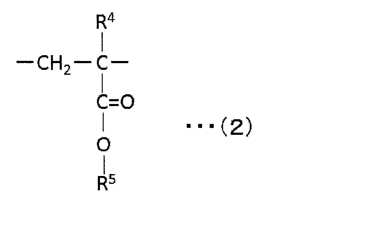
- R 4 represents a hydrogen atom or a methyl group
- R 5 represents a hydrogen atom or an optionally substituted aliphatic or alicyclic hydrocarbon group having 1 to 6 carbon atoms. Show.
- the substituent include halogen and hydroxyl group.
- Specific examples of the alkyl (meth) acrylate include methyl (meth) acrylate, ethyl (meth) acrylate, n-propyl (meth) acrylate, n-butyl (meth) acrylate, and t- (meth) acrylate.
- R 5 is preferably a hydrogen atom or a methyl group. Accordingly, particularly preferred alkyl (meth) acrylates are methyl acrylate or methyl methacrylate.
- the acrylic resin may contain only a single glutarimide unit, or may contain a plurality of glutarimide units in which R 1 , R 2 and R 3 in the general formula (1) are different.
- the content ratio of the glutarimide unit in the acrylic resin is preferably 2 mol% to 50 mol%, more preferably 2 mol% to 45 mol%, still more preferably 2 mol% to 40 mol%, and particularly preferably 2 mol%. % To 35 mol%, most preferably 3 mol% to 30 mol%.
- the content ratio is less than 2 mol%, the effects expressed from the glutarimide unit (for example, high optical characteristics, high mechanical strength, excellent adhesiveness with a polarizer, thinning) are sufficiently exerted. There is a risk that it will not be.
- the content ratio exceeds 50 mol%, for example, heat resistance and transparency may be insufficient.
- the acrylic resin may include only a single alkyl (meth) acrylate unit, or may include a plurality of alkyl (meth) acrylate units in which R 4 and R 5 in the general formula (2) are different. Also good.
- the content ratio of the alkyl (meth) acrylate unit in the acrylic resin is preferably 50 mol% to 98 mol%, more preferably 55 mol% to 98 mol%, still more preferably 60 mol% to 98 mol%, particularly preferably. Is from 65 mol% to 98 mol%, most preferably from 70 mol% to 97 mol%. If the content ratio is less than 50 mol%, the effects expressed from the alkyl (meth) acrylate unit (for example, high heat resistance and high transparency) may not be sufficiently exhibited. If the content is more than 98 mol%, the resin is brittle and easily cracked, and high mechanical strength cannot be exhibited sufficiently, which may result in poor productivity.
- the acrylic resin may contain units other than glutarimide units and alkyl (meth) acrylate units.
- the acrylic resin can contain, for example, 0 to 10% by weight of an unsaturated carboxylic acid unit that is not involved in the intramolecular imidation reaction described later.
- the content ratio of the unsaturated carboxylic acid unit is preferably 0 to 5% by weight, more preferably 0 to 1% by weight. When the content is in such a range, transparency, retention stability and moisture resistance can be maintained.
- the acrylic resin may contain copolymerizable vinyl monomer units (other vinyl monomer units) other than those described above.
- vinyl monomers include acrylonitrile, methacrylonitrile, ethacrylonitrile, allyl glycidyl ether, maleic anhydride, itaconic anhydride, N-methylmaleimide, N-ethylmaleimide, N-cyclohexylmaleimide, acrylic Aminoethyl acid, propylaminoethyl acrylate, dimethylaminoethyl methacrylate, ethylaminopropyl methacrylate, cyclohexylaminoethyl methacrylate, N-vinyldiethylamine, N-acetylvinylamine, allylamine, methallylamine, N-methylallylamine, 2 -Isopropenyl-oxazoline, 2-vinyl-oxazoline, 2-acryloy
- Styrene monomers such as styrene and ⁇ -methylstyrene are preferable.
- the content of other vinyl monomer units is preferably 0 to 1% by weight, more preferably 0 to 0.1% by weight. If it is such a range, the expression of the phase difference and the fall of transparency which are not desired can be suppressed.
- the imidization ratio in the acrylic resin is preferably 2.5% to 20.0%. If the imidation ratio is in such a range, a resin excellent in heat resistance, transparency and molding processability can be obtained, and the occurrence of kogation and a decrease in mechanical strength during film molding can be prevented.
- the imidization rate is represented by a ratio of a glutarimide unit and an alkyl (meth) acrylate unit. This ratio can be obtained from, for example, the NMR spectrum, IR spectrum, etc. of the acrylic resin.
- the imidization ratio can be determined by 1 H-NMR measurement of the resin using 1 H NMR BRUKER Avance III (400 MHz).
- the peak area derived from the O—CH 3 proton of alkyl (meth) acrylate in the vicinity of 3.5 to 3.8 ppm is defined as A, and N—CH 3 of glutarimide in the vicinity of 3.0 to 3.3 ppm.
- the acid value of the acrylic resin is preferably 0.10 mmol / g to 0.50 mmol / g. If the acid value is within such a range, a resin having a good balance of heat resistance, mechanical properties and molding processability can be obtained. If the acid value is too small, there may be problems such as an increase in cost due to the use of a modifier for adjusting to a desired acid value, and generation of a gel-like material due to the remaining modifier. When the acid value is too large, foaming at the time of film forming (for example, at the time of melt extrusion) tends to occur, and the productivity of the molded product tends to decrease.
- the acid value is the content of carboxylic acid units and carboxylic anhydride units in the acrylic resin. In the present embodiment, the acid value can be calculated by, for example, a titration method described in WO2005 / 054311 or JP-A-2005-23272.
- the weight average molecular weight of the acrylic resin is preferably 1,000 to 2,000,000, more preferably 5,000 to 1,000,000, still more preferably 10,000 to 500,000, particularly preferably 50,000 to 500,000, and most preferably 60000 to 150,000.
- a weight average molecular weight can be calculated
- the acrylic resin has a Tg (glass transition temperature) of preferably 110 ° C. or higher, more preferably 115 ° C. or higher, further preferably 120 ° C. or higher, particularly preferably 125 ° C. or higher, and most preferably 130 ° C. or higher. If Tg is 110 degreeC or more, the polarizing plate containing the 1st protective film obtained from such resin will become the thing excellent in durability.
- the upper limit value of Tg is preferably 300 ° C. or lower, more preferably 290 ° C. or lower, further preferably 285 ° C. or lower, particularly preferably 200 ° C. or lower, and most preferably 160 ° C. or lower. If Tg is in such a range, the moldability can be excellent.
- the acrylic resin can be produced, for example, by the following method. This method comprises (I) an alkyl (meth) acrylate monomer corresponding to the alkyl (meth) acrylate unit represented by the general formula (2), an unsaturated carboxylic acid monomer and / or a precursor thereof To obtain a copolymer (a); and (II) treating the copolymer (a) with an imidizing agent to give a copolymer (a) in the copolymer (a).
- An intramolecular imidation reaction of the alkyl (meth) acrylate monomer unit and the unsaturated carboxylic acid monomer and / or its precursor monomer unit is carried out to share the glutarimide unit represented by the general formula (1). Introducing into the polymer.
- Examples of the unsaturated carboxylic acid monomer include acrylic acid, methacrylic acid, crotonic acid, ⁇ -substituted acrylic acid, and ⁇ -substituted methacrylic acid.
- Examples of the precursor monomer include acrylamide and methacrylamide. These may be used alone or in combination.
- a preferred unsaturated carboxylic acid monomer is acrylic acid or methacrylic acid, and a preferred precursor monomer is acrylamide.
- Any appropriate method can be used as a method for treating the copolymer (a) with an imidizing agent.
- Specific examples include a method using an extruder and a method using a batch type reaction vessel (pressure vessel).
- the method using an extruder includes heating and melting the copolymer (a) using an extruder and treating it with an imidizing agent.
- any appropriate extruder can be used as the extruder.
- Specific examples include a single screw extruder, a twin screw extruder, and a multi-screw extruder.
- any appropriate batch type reaction vessel pressure vessel can be used.
- the imidizing agent any appropriate compound can be used as long as the glutarimide unit represented by the general formula (1) can be generated.
- Specific examples of the imidizing agent include amines containing aliphatic hydrocarbon groups such as methylamine, ethylamine, n-propylamine, i-propylamine, n-butylamine, i-butylamine, tert-butylamine, n-hexylamine, Examples include aromatic hydrocarbon group-containing amines such as aniline, benzylamine, toluidine, and trichloroaniline, and alicyclic hydrocarbon group-containing amines such as cyclohexylamine.
- a urea compound that generates such an amine by heating can be used.
- the urea compound include urea, 1,3-dimethylurea, 1,3-diethylurea, and 1,3-dipropylurea.
- the imidizing agent is preferably methylamine, ammonia, or cyclohexylamine, more preferably methylamine.
- a ring closure accelerator may be added as necessary.
- the amount of the imidizing agent used in the imidization is preferably 0.5 to 10 parts by weight, more preferably 0.5 to 6 parts by weight with respect to 100 parts by weight of the copolymer (a). It is. If the amount of the imidizing agent used is less than 0.5 parts by weight, the desired imidization rate is often not achieved. As a result, the heat resistance of the resulting resin becomes extremely insufficient, which may induce appearance defects such as burnt after molding. When the amount of the imidizing agent used exceeds 10 parts by weight, the imidizing agent remains in the resin, and the imidizing agent may induce appearance defects such as burnt after molding and foaming.
- the production method of the present embodiment can include treatment with an esterifying agent in addition to the imidization as necessary.
- esterifying agent examples include dimethyl carbonate, 2,2-dimethoxypropane, dimethyl sulfoxide, triethyl orthoformate, trimethyl orthoacetate, trimethyl orthoformate, diphenyl carbonate, dimethyl sulfate, methyl toluene sulfonate, methyl trifluoromethane sulfonate, Methyl acetate, methanol, ethanol, methyl isocyanate, p-chlorophenyl isocyanate, dimethylcarbodiimide, dimethyl-t-butylsilyl chloride, isopropenyl acetate, dimethylurea, tetramethylammonium hydroxide, dimethyldiethoxysilane, tetra-N-butoxysilane , Dimethyl (trimethylsilane) phosphite, trimethyl phosphite , Trimethyl phosphate, tricresyl phosphate, diazomethane, ethylene oxide
- the addition amount of the esterifying agent can be set so that the acid value of the acrylic resin becomes a desired value.
- the acrylic resin and other resins may be used in combination. That is, the monomer component constituting the acrylic resin and the monomer component constituting the other resin may be copolymerized, and the copolymer may be used for film formation described later in Section D; the acrylic resin and the other resin.
- the blend may be used for film formation.
- resins include, for example, styrene resins, polyethylene, polypropylene, polyamide, polyphenylene sulfide, polyether ether ketone, polyester, polysulfone, polyphenylene oxide, polyacetal, polyimide, polyetherimide, and other thermoplastic resins, phenolic Examples thereof include thermosetting resins such as resins, melamine resins, polyester resins, silicone resins, and epoxy resins.
- the type and blending amount of the resin to be used in combination can be appropriately set according to the purpose and the properties desired for the obtained film.
- a styrene resin preferably, acrylonitrile-styrene copolymer
- phase difference controlling agent preferably, acrylonitrile-styrene copolymer
- the content of the acrylic resin in the blend of the acrylic resin and the other resin is preferably 50% by weight to 100% by weight, more preferably 60% by weight to 100%. % By weight, more preferably 70% by weight to 100% by weight, particularly preferably 80% by weight to 100% by weight. When the content is less than 50% by weight, the high heat resistance and high transparency inherent in the acrylic resin may not be sufficiently reflected.
- the core-shell type particles are preferably blended in an amount of 3 to 25 parts by weight, more preferably 5 to 20 parts by weight with respect to 100 parts by weight of the acrylic resin.
- the core-shell type particles typically have a core made of a rubber-like polymer and a coating layer made of a glassy polymer and covering the core.
- the core-shell type particle may have one or more layers made of a glassy polymer as the innermost layer or the intermediate layer.
- the Tg of the rubbery polymer constituting the core is preferably 20 ° C. or less, more preferably ⁇ 60 ° C. to 20 ° C., and further preferably ⁇ 60 ° C. to 10 ° C. If the Tg of the rubbery polymer constituting the core exceeds 20 ° C, the mechanical strength of the acrylic resin may not be sufficiently improved.
- the Tg of the glassy polymer (hard polymer) constituting the coating layer is preferably 50 ° C. or higher, more preferably 50 ° C. to 140 ° C., and further preferably 60 ° C. to 130 ° C. When Tg of the glassy polymer constituting the coating layer is lower than 50 ° C., the heat resistance of the acrylic resin may be lowered.
- the core content in the core-shell type particles is preferably 30% to 95% by weight, more preferably 50% to 90% by weight.
- the ratio of the glassy polymer layer in the core is 0 to 60% by weight, preferably 0 to 45% by weight, and more preferably 10 to 40% by weight with respect to 100% by weight of the total amount of the core.
- the content of the coating layer in the core-shell type particle is preferably 5% by weight to 70% by weight, more preferably 10% by weight to 50% by weight.
- the core-shell particles dispersed in the acrylic resin may have a flat shape.
- the core-shell type particles can be flattened by stretching described later in Section C-4.
- the length / thickness ratio of the flattened core-shell type particles is 7.0 or less.
- the length / thickness ratio is preferably 6.5 or less, and more preferably 6.3 or less.
- the length / thickness ratio is preferably 4.0 or more, more preferably 4.5 or more, and further preferably 5.0 or more.
- the “ratio of length / thickness” means the ratio of the representative length and thickness of the core-shell type particle in plan view.
- the “representative length” means a diameter when the shape in plan view is circular, a long diameter when the shape is elliptical, and a diagonal length when the shape is rectangular or polygonal.
- the ratio can be obtained, for example, by the following procedure. The cross section of the obtained film was photographed with a transmission electron microscope (for example, acceleration voltage 80 kV, RuO 4 dyeing ultrathin section method), and the long core-shell type particles present in the obtained photograph (cross section close to the representative length) The ratio can be obtained by extracting 30 pieces in order from the one obtained and calculating (average length) / (average thickness).
- the first protective film according to the embodiment of the present invention includes the acrylic resin (in the case of using other resins in combination, blends with the other resins) and the core shell. It can be formed by a method comprising film-forming a composition comprising mold particles. Further, the method of forming the first protective film can include stretching the film.
- the average particle diameter of the core-shell type particles used for film formation is preferably 1 nm to 500 nm.
- the average particle diameter of the core is preferably 50 nm to 300 nm, more preferably 70 nm to 300 nm.
- Arbitrary appropriate methods can be employ
- Specific examples include cast coating methods (for example, casting methods), extrusion molding methods, injection molding methods, compression molding methods, transfer molding methods, blow molding methods, powder molding methods, FRP molding methods, calendar molding methods, and hot presses. Law.
- the extrusion molding method or the cast coating method is preferable. This is because the smoothness of the resulting film can be improved and good optical uniformity can be obtained.
- Particularly preferred is an extrusion method. This is because it is not necessary to consider the problem due to the residual solvent. Among these, an extrusion method using a T die is preferable from the viewpoint of film productivity and ease of subsequent stretching treatment.
- the molding conditions can be appropriately set according to the composition and type of the resin used, the properties desired for the resulting film, and the like.
- any appropriate stretching method and stretching conditions for example, stretching temperature, stretching ratio, stretching speed, stretching direction
- the stretching method include free end stretching, fixed end stretching, free end contraction, and fixed end contraction. These may be used alone, may be used simultaneously, or may be used sequentially.
- the stretching direction can be an appropriate direction depending on the purpose. Specifically, a length direction, a width direction, a thickness direction, and an oblique direction are mentioned.
- the stretching direction may be one direction (uniaxial stretching), two directions (biaxial stretching), or three or more directions. In the embodiment of the present invention, typically, uniaxial stretching in the length direction, simultaneous biaxial stretching in the length direction and width direction, and sequential biaxial stretching in the length direction and width direction may be employed. Biaxial stretching (simultaneous or sequential) is preferable. This is because the in-plane phase difference can be easily controlled and optical isotropy can be easily realized.
- the stretching temperature is the optical properties, mechanical properties and thickness desired for the first protective film, the type of resin used, the thickness of the film used, the stretching method (uniaxial stretching or biaxial stretching), the stretching ratio. Depending on the stretching speed, etc. Specifically, the stretching temperature is preferably Tg to Tg + 50 ° C., more preferably Tg + 15 ° C. to Tg + 50 ° C., and most preferably Tg + 35 ° C. to Tg + 50 ° C. By stretching at such a temperature, a first protective film having appropriate characteristics can be obtained.
- the specific stretching temperature is, for example, 110 ° C. to 200 ° C., preferably 120 ° C. to 190 ° C. When the stretching temperature is in such a range, the bending resistance and handling properties of the polarizing plate when the first protective film is applied to the polarizing plate can be improved by appropriately adjusting the stretching ratio and the stretching speed. .
- the stretching ratio is also the same as the stretching temperature: optical properties, mechanical properties and thickness, type of resin used, film thickness used, stretching method (uniaxial stretching or biaxial stretching), stretching temperature, stretching It can vary depending on speed and the like.
- the ratio (TD / MD) of the stretching ratio in the width direction (TD) and the stretching ratio in the length direction (MD) is preferably 1.0 to 1.5, more preferably Is 1.0 to 1.4, more preferably 1.0 to 1.3.
- the plane magnification (product of the draw ratio in the length direction and the draw ratio in the width direction) when employing biaxial stretching is preferably 2.0 to 6.0, more preferably 3.0 to 5.5, and more preferably 3.5 to 5.2. If the draw ratio is in such a range, the bending resistance and handling properties of the polarizing plate when the first protective film is applied to the polarizing plate can be improved by appropriately adjusting the drawing temperature and the drawing speed. .
- Stretching speed is also the same as stretching temperature: optical properties, mechanical properties and thickness, type of resin used, film thickness used, stretching method (uniaxial stretching or biaxial stretching), stretching temperature, stretching It can change depending on the magnification or the like.
- the stretching speed is preferably 3% / second to 20% / second, more preferably 3% / second to 15% / second, and further preferably 3% / second to 10% / second.
- biaxial stretching is employed, the stretching speed in one direction and the stretching speed in the other direction may be the same or different. If the stretching speed is in such a range, the bending resistance and handling properties of the polarizing plate when the first protective film is applied to the polarizing plate can be improved by appropriately adjusting the stretching temperature and the stretching ratio. .
- the first protective film can be formed.
- the second protective film includes an acrylic resin in which core-shell particles are dispersed as described above. In another embodiment, the second protective film does not include core-shell type particles.
- the film which comprises a 2nd protective film is as having demonstrated the 1st protective film by C term.
- the surface treatment layer is any suitable functional layer formed on one side of the first protective film or the second protective film depending on the function required for the polarizing plate.
- Specific examples of the surface treatment layer include a hard coat layer, an antiglare layer, and an antireflection layer.
- the thickness of the surface treatment layer is preferably 2 ⁇ m to 30 ⁇ m, more preferably 5 ⁇ m to 25 ⁇ m.
- the surface treatment layer is typically a cured layer of a resin composition formed on the first protective film or the second protective film (hereinafter simply referred to as “protective film”).
- the step of forming the surface treatment layer includes forming a coating layer by applying the resin composition for forming the surface treatment layer on the protective film, and drying and curing the coating layer to form a surface treatment layer. May be included. Drying and curing the coating layer can include heating the coating layer.
- the resin composition preferably contains a solvent for dilution.
- the heating temperature of the coating layer can be set to any appropriate temperature according to the composition of the resin composition, and is preferably set to be equal to or lower than the glass transition temperature of the acrylic resin contained in the protective film. If it heats at the temperature below the glass transition temperature of the acrylic resin contained in a protective film, the protective film by which the deformation
- the heating temperature of the coating layer is, for example, 60 ° C. to 140 ° C., preferably 70 ° C. to 100 ° C. By heating at such a heating temperature, a protective film having excellent adhesion between the protective film and the surface treatment layer can be obtained.
- the hard coat layer is a layer that imparts scratch resistance, chemical resistance, and the like to the surface of the protective film.
- the hard coat layer preferably has a hardness of H or higher, more preferably 3H or higher, in a pencil hardness test.
- the pencil hardness test can be measured according to JIS K 5400.
- the resin composition for forming the hard coat layer may contain, for example, a curable compound that can be cured by heat, light (such as ultraviolet rays), or an electron beam. Details of the hard coat layer and the resin composition for forming the hard coat layer are described in, for example, JP-A-2014-240955. This publication is incorporated herein by reference in its entirety.
- the antiglare layer is a layer for preventing reflection of external light by scattering and reflecting light.
- the resin composition for forming an antiglare layer can contain, for example, a curable compound that can be cured by heat, light (such as ultraviolet rays), or an electron beam.
- the antiglare layer typically has a fine uneven shape on the surface. Examples of a method for forming such a fine concavo-convex shape include a method in which fine particles are contained in the curable compound. Details of the antiglare layer and the resin composition for forming the antiglare layer are described in, for example, JP-A-2017-32711. This publication is incorporated herein by reference in its entirety.
- the antireflection layer is a layer for preventing reflection of external light.
- the resin composition for forming the antireflection layer can contain, for example, a curable compound that can be cured by heat, light (such as ultraviolet rays), or an electron beam.
- the antireflection layer may be a single layer composed of only one layer or a plurality of layers composed of two or more layers. Details of the antireflection layer and the resin composition for forming the antireflection layer are described in, for example, JP-A-2012-155050. This publication is incorporated herein by reference in its entirety.
- the present invention also includes an image display device using such a polarizing plate.
- Typical examples of the image display device include a liquid crystal display device and an organic electroluminescence (EL) display device.
- the image display device includes the polarizing plate described in the items A to E.
- the number of times was used as an index of bending resistance.
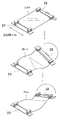
- the bending test is performed according to the following procedure using a planar body no-load U-shaped expansion test machine (product name: main body DLDM111LH and jig: planar body no-load U-shaped expansion test jig) manufactured by Yuasa System Equipment Co., Ltd. It was. As shown in FIG.
- both end portions x and y (50 mm) of a sheet-like polarizing plate of 100 mm (absorption axis direction) ⁇ 50 mm (transmission axis direction) are attached to the support portions 21 and 22 of the tester with a double-sided tape ( After fixing with a not-shown), the polarizing plate is bent by performing expansion and contraction such that one side (first surface) of the polarizing plate becomes U-shaped inside.
- the bending R bending radius
- the polarizing plate is folded in a folded state from a flat state.
- both ends x and y are brought into contact with both ends x and y by the operation of the support portion, and the other portions of the polarizing plate are loaded from the outside by both plate portions 23 and 24 separately provided. Touch it as if it were pinched. Further, the bending by the expansion and contraction is similarly performed on the other side (second surface) of the polarizing plate so as to be U-shaped inward. Telescopic speed: 60rpm Bending R: 6mm Inner Bending / Bending Test Bending was repeated with a bending diameter of 6 mm so that the first protective film was inside (the second protective film was outside).
- monomethylamine imidation ratio: 5%
- the obtained imidized MS resin is represented by a general formula (1), a glutarimide unit (R 1 and R 3 are methyl groups, R 2 is a hydrogen atom), and a general formula (2) ( It had a (meth) acrylic acid ester unit (R 4 and R 5 are methyl groups), and a styrene unit.
- a meshing type co-rotating twin screw extruder having a diameter of 15 mm was used.
- the set temperature of each temperature control zone of the extruder is 230 ° C.
- the screw rotation speed is 150 rpm
- MS resin is supplied at 2.0 kg / hr
- the supply amount of monomethylamine is 2 parts by weight with respect to 100 parts by weight of MS resin.
- MS resin was introduced from the hopper, and the resin was melted and filled with a kneading block, and then monomethylamine was injected from the nozzle. A seal ring was placed at the end of the reaction zone to fill the resin.
- the by-product after reaction and excess methylamine were devolatilized by reducing the pressure at the vent port to -0.08 MPa.
- the resin that came out as a strand from a die provided at the exit of the extruder was cooled in a water tank and then pelletized with a pelletizer.
- the imidization rate of the obtained imidized MS resin was 5.0%, and the acid value was 0.5 mmol / g. 100 parts by weight of the imidized MS resin obtained above and 15 parts by weight of core-shell type particles were put into a single screw extruder, melt mixed, and a film was formed through a T die to obtain an extruded film having a thickness of 120 ⁇ m. .
- the obtained extruded film was simultaneously biaxially stretched twice in the length direction and the width direction at a stretching temperature of 150 ° C.
- the stretching speed was 10% / second in both the length direction and the width direction.
- the protective film A was produced.
- the thickness of the protective film A obtained was 30 ⁇ m, and the elastic modulus of the protective film A was 3.8 GPa.
- Polarizer ⁇ Production Example 9> (Polarizer A) One side of an amorphous isophthalic acid copolymerized polyethylene terephthalate (IPA copolymerized PET) film (thickness: 100 ⁇ m) having a water absorption of 0.75% and Tg of 75 ° C. is subjected to corona treatment. Alcohol (polymerization degree 4200, saponification degree 99.2 mol%) and acetoacetyl-modified PVA (polymerization degree 1200, acetoacetyl modification degree 4.6%, saponification degree 99.0 mol% or more, manufactured by Nippon Synthetic Chemical Industry Co., Ltd.
- aqueous solution containing 9: 1 ratio of the trade name “Gosefimer Z200”) was applied and dried at 25 ° C. to form a PVA-based resin layer having a thickness of 11 ⁇ m, thereby preparing a laminate.
- the obtained laminate was uniaxially stretched in the longitudinal direction (longitudinal direction) 2.0 times between rolls having different peripheral speeds in an oven at 120 ° C. (air-assisted stretching process).
- the laminate was immersed in an insolubilization bath (a boric acid aqueous solution obtained by blending 4 parts by weight of boric acid with respect to 100 parts by weight of water) for 30 seconds (insolubilization treatment).
- boric acid aqueous solution obtained by blending 3 parts by weight of potassium iodide and 3 parts by weight of boric acid with respect to 100 parts by weight of water.
- Crosslinking treatment Thereafter, the laminated body is added to a boric acid aqueous solution (an aqueous solution obtained by blending 3.75 parts by weight of boric acid and 5 parts by weight of potassium iodide with respect to 100 parts by weight of water) at a liquid temperature of 70 ° C. While being immersed, uniaxial stretching was performed in the longitudinal direction (longitudinal direction) between rolls having different peripheral speeds so that the total stretching ratio was 5.5 times (in-water stretching treatment).
- the laminate was immersed in a cleaning bath (an aqueous solution obtained by blending 4 parts by weight of potassium iodide with respect to 100 parts by weight of water) at a liquid temperature of 30 ° C. (cleaning treatment).
- a cleaning bath an aqueous solution obtained by blending 4 parts by weight of potassium iodide with respect to 100 parts by weight of water
- cleaning treatment a liquid temperature of 30 ° C.
- IPA copolymerized PET amorphous isophthalic acid copolymerized polyethylene terephthalate (IPA copolymerized PET) film (thickness: 100 ⁇ m) having a water absorption of 0.75% and Tg of 75 ° C. is subjected to corona treatment.
- Alcohol polymerization degree 4200, saponification degree 99.2 mol%) and acetoacetyl-modified PVA (polymerization degree 1200, acetoacetyl modification degree 4.6%, saponification degree 99.0 mol% or more, manufactured by Nippon Synthetic Chemical Industry Co., Ltd.
- an aqueous solution containing 9: 1 ratio of trade name “Gosefimer Z200”) was applied and dried at 25 ° C. to form a PVA resin layer having a thickness of 15 ⁇ m, and a laminate was produced.
- the obtained laminate was uniaxially stretched in the longitudinal direction (longitudinal direction) 2.0 times between rolls having different peripheral speeds in an oven at 120 ° C. (air-assisted stretching process).
- the laminate was immersed in an insolubilization bath (a boric acid aqueous solution obtained by blending 4 parts by weight of boric acid with respect to 100 parts by weight of water) for 30 seconds (insolubilization treatment).
- boric acid aqueous solution obtained by blending 3 parts by weight of potassium iodide and 3 parts by weight of boric acid with respect to 100 parts by weight of water.
- Crosslinking treatment Thereafter, the laminated body is added to a boric acid aqueous solution (an aqueous solution obtained by blending 3.75 parts by weight of boric acid and 5 parts by weight of potassium iodide with respect to 100 parts by weight of water) at a liquid temperature of 70 ° C. While being immersed, uniaxial stretching was performed in the longitudinal direction (longitudinal direction) between rolls having different peripheral speeds so that the total stretching ratio was 5.5 times (in-water stretching treatment).
- an optical film laminate B including a polarizer B having a thickness of 7 ⁇ m was obtained.
- IPA copolymerized PET amorphous isophthalic acid copolymerized polyethylene terephthalate (IPA copolymerized PET) film (thickness: 100 ⁇ m) having a water absorption of 0.75% and Tg of 75 ° C. is subjected to corona treatment.
- Alcohol polymerization degree 4200, saponification degree 99.2 mol%) and acetoacetyl-modified PVA (polymerization degree 1200, acetoacetyl modification degree 4.6%, saponification degree 99.0 mol% or more, manufactured by Nippon Synthetic Chemical Industry Co., Ltd.
- an aqueous solution containing 9: 1 ratio of the trade name “Gosefimmer Z200”) was applied and dried at 25 ° C. to form a PVA resin layer having a thickness of 30 ⁇ m, and a laminate was produced.
- the obtained laminate was uniaxially stretched in the longitudinal direction (longitudinal direction) 2.0 times between rolls having different peripheral speeds in an oven at 120 ° C. (air-assisted stretching process).
- the laminate was immersed in an insolubilization bath (a boric acid aqueous solution obtained by blending 4 parts by weight of boric acid with respect to 100 parts by weight of water) for 30 seconds (insolubilization treatment).
- boric acid aqueous solution obtained by blending 3 parts by weight of potassium iodide and 3 parts by weight of boric acid with respect to 100 parts by weight of water.
- Crosslinking treatment Thereafter, the laminated body is added to a boric acid aqueous solution (an aqueous solution obtained by blending 3.75 parts by weight of boric acid and 5 parts by weight of potassium iodide with respect to 100 parts by weight of water) at a liquid temperature of 70 ° C. While being immersed, uniaxial stretching was performed in the longitudinal direction (longitudinal direction) between rolls having different peripheral speeds so that the total stretching ratio was 5.5 times (in-water stretching treatment).
- an optical film laminate C including a polarizer C having a thickness of 12 ⁇ m was obtained.
- ⁇ Production Example 14> As a resin contained in the coating liquid, an ultraviolet curable resin (manufactured by Shin-Nakamura Chemical Co., Ltd., trade name “NK oligomer UA-53H-80BK” solid content concentration 80%) is 70 parts by weight solid content, an ultraviolet curable type. 30 parts by weight of resin (manufactured by Shin-Nakamura Chemical Co., Ltd., trade name “A-GLY-9E” solid content concentration 100%) was prepared.
- UV curable adhesive ⁇ Production Example 15> An ultraviolet curable adhesive was prepared by mixing 40 parts by weight of N-hydroxyethylacrylamide (HEAA), 60 parts by weight of acryloylmorpholine (ACMO), and 3 parts by weight of a photoinitiator “IRGACURE 819” (manufactured by BASF).
- HEAA N-hydroxyethylacrylamide
- ACMO acryloylmorpholine
- Adhesive layer ⁇ Production Example 16> In a reaction vessel equipped with a cooling tube, a nitrogen introduction tube, a thermometer and a stirrer, 100 parts of butyl acrylate, 3 parts of acrylic acid, 0.1 part of 2-hydroxyethyl acrylate and 2,2′-azobisisobutyrate A solution was prepared by adding 0.3 parts of ronitrile with ethyl acetate. Next, the solution was stirred while blowing nitrogen gas and reacted at 55 ° C. for 8 hours to obtain a solution containing an acrylic polymer having a weight average molecular weight of 2.2 million.
- the acrylic polymer solution which added ethyl acetate to the solution containing this acrylic polymer and adjusted solid content concentration to 30% was obtained.
- a cross-linking agent 100 parts by weight of the solid content of the acrylic polymer solution is a cross-linking agent mainly composed of a compound having an isocyanate group of 0.5 part (trade name “Coronate L” manufactured by Nippon Polyurethane Co., Ltd.). And 0.075 parts of ⁇ -glycidoxypropyltrimethoxysilane (manufactured by Shin-Etsu Chemical Co., Ltd., trade name “KMB-403”) as a silane coupling agent in this order, was prepared.
- the pressure-sensitive adhesive solution was applied to the surface of a release sheet (separator) made of a peeled polyethylene terephthalate film (thickness 38 ⁇ m) so that the thickness after drying was 20 ⁇ m and dried to form a pressure-sensitive adhesive layer. Formed.
- the protective film B was used as the first protective film.
- the material for forming the hard coat layer A was applied so that the thickness of the hard coat layer after curing was 6.5 ⁇ m to form a coating film. Subsequently, it is dried at 90 ° C. for 1 minute, and then irradiated with ultraviolet rays with an integrated light quantity of 300 mJ / cm 2 with a high-pressure mercury lamp, and the coating film is cured to form a hard coat layer A on the surface of the protective film B. Formed.
- the protective film is applied to the surface of the polarizer A of the optical film laminate A while applying the ultraviolet curable adhesive of Production Example 15 so that the thickness of the adhesive layer after curing is 0.5 ⁇ m.
- ultraviolet rays were irradiated as active energy rays to cure the adhesive.
- Ultraviolet irradiation is performed using a gallium-encapsulated metal halide lamp, an irradiation device: Fusion UV Systems, Inc.
- Example 1 ⁇ Examples 2 to 13 and Comparative Examples 1 and 2>
- the polarizer, the first protective film, the second protective film, and the surface treatment layer were changed in the same manner as in Example 1 except that the adhesive layer was attached.
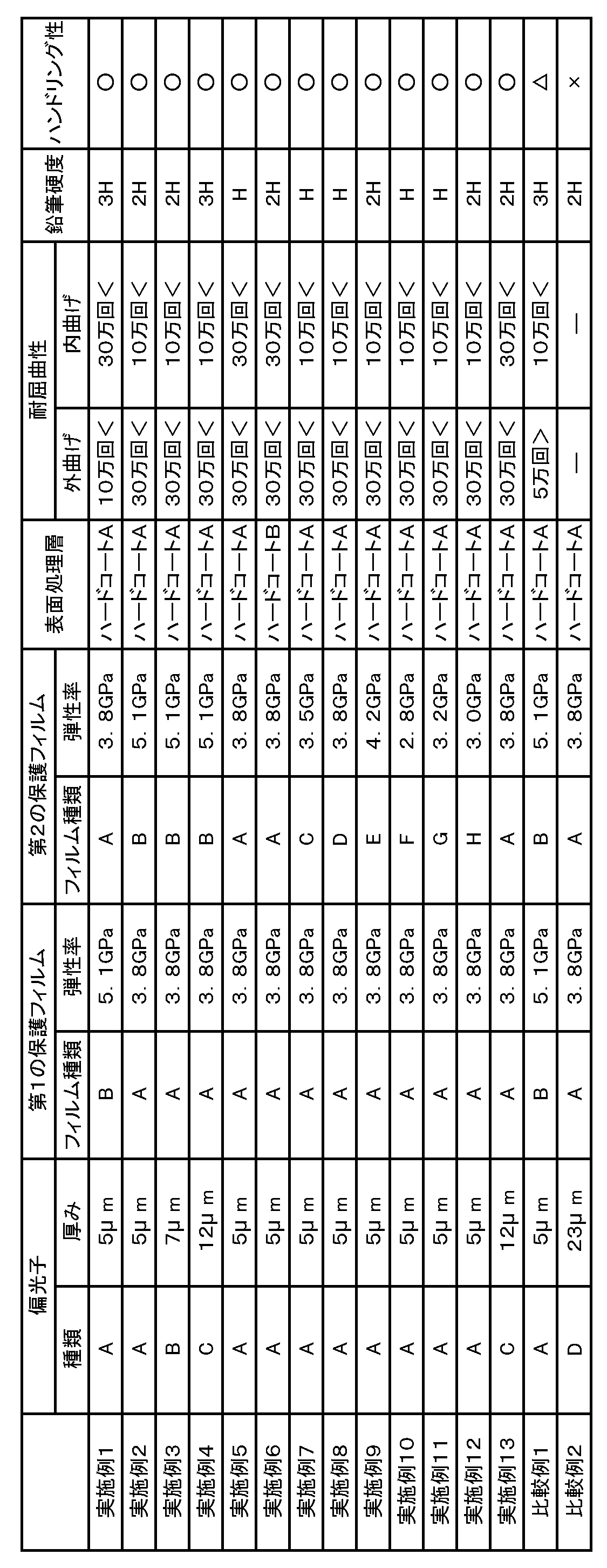
- a polarizing plate was produced. The said polarizing plate was used for each evaluation. The results are shown in Table 1.
- the polarizing plates of Comparative Examples 1 and 2 had low bending resistance and handling properties.
- the polarizer cracked immediately after the start of the bending test.
- the polarizing plates of Examples 1 to 13 were excellent in bending resistance and handling properties.
- the polarizing plate of the present invention is suitably used for an image display device.
- the image display device according to the present invention includes portable devices such as personal digital assistants (PDAs), smart phones, mobile phones, watches, digital cameras, and portable game machines; OA devices such as personal computer monitors, notebook computers, and copy machines; Household electrical equipment such as microwave ovens; back monitors, car navigation system monitors, car audio equipment such as car audio; display equipment such as digital signage and commercial store information monitors; security equipment such as monitoring monitors; It can be used for various purposes such as nursing care / medical equipment such as medical monitors and medical monitors.
- PDAs personal digital assistants
- OA devices such as personal computer monitors, notebook computers, and copy machines
- Household electrical equipment such as microwave ovens
- display equipment such as digital signage and commercial store information monitors
- security equipment such as monitoring monitors
- It can be used for various purposes such as nursing care / medical equipment such as medical monitors and medical
Landscapes
- Physics & Mathematics (AREA)
- General Physics & Mathematics (AREA)
- Chemical & Material Sciences (AREA)
- Optics & Photonics (AREA)
- Chemical Kinetics & Catalysis (AREA)
- Organic Chemistry (AREA)
- Medicinal Chemistry (AREA)
- Polymers & Plastics (AREA)
- Health & Medical Sciences (AREA)
- Nonlinear Science (AREA)
- Mathematical Physics (AREA)
- Crystallography & Structural Chemistry (AREA)
- Engineering & Computer Science (AREA)
- Theoretical Computer Science (AREA)
- Polarising Elements (AREA)
- Devices For Indicating Variable Information By Combining Individual Elements (AREA)
- Liquid Crystal (AREA)
- Surface Treatment Of Optical Elements (AREA)
Abstract
Description
1つの実施形態においては、上記第1および第2の保護フィルムの少なくとも一方は、上記アクリル系樹脂100重量部に対して、上記コアシェル型粒子を3重量部~20重量部含有する。
1つの実施形態においては、上記第1の保護フィルムが、上記アクリル系樹脂と、上記コアシェル型粒子と、を含み、上記第1の保護フィルムの厚みが30μm以下である。
1つの実施形態においては、上記アクリル系樹脂が、グルタルイミド単位、ラクトン環単位、無水マレイン酸単位、マレイミド単位および無水グルタル酸単位からなる群から選択される少なくとも1つを有する。
1つの実施形態においては、屈曲試験において上記偏光子に割れが生じるまでの屈曲回数が10万回以上であり、鉛筆硬度がH以上である。
1つの実施形態においては、上記第1の保護フィルムが、上記アクリル系樹脂と、上記コアシェル型粒子と、を含み、上記第1の保護フィルムが外側となるように屈曲させる屈曲試験において、上記偏光子に割れが生じるまでの屈曲回数が30万回以上である。
1つの実施形態においては、上記第2の保護フィルムが上記コアシェル型粒子を含まない。
1つの実施形態においては、上記第1の保護フィルムまたは上記第2の保護フィルムの上記偏光子とは反対側の面に表面処理層が配置されており、上記表面処理層が、ハードコート層、防眩層および反射防止層からなる群から選択される少なくとも1つである。
本発明の別の局面によれば、画像表示装置が提供される。この画像表示装置は、上記偏光板を備える。
図1は、本発明の1つの実施形態による偏光板の断面図である。偏光板100は、偏光子10と、偏光子10の一方の側に配置された第1の保護フィルム20と、偏光子の他方の側に配置された第2の保護フィルム30と、を有する。偏光子10の厚みは12μm以下である。第1の保護フィルム20および第2の保護フィルム30の少なくとも何れか一方は、コアシェル型粒子が分散されたアクリル系樹脂を含む。これにより、偏光板の耐屈曲性およびハンドリング性を向上し得る。特に、第1および第2の保護フィルムを薄型化した場合であっても、偏光板の耐屈曲性およびハンドリング性を向上し得る。偏光板100は、画像表示装置の表示セルの視認側および/または背面側の偏光板として用いられ得る。
偏光子としては、任意の適切な偏光子が採用され得る。例えば、偏光子を形成する樹脂フィルムは、単層の樹脂フィルムであってもよく、二層以上の積層体であってもよい。
C-1.第1の保護フィルムの特性
1つの実施形態においては、第1の保護フィルムは、コアシェル型粒子が分散されたアクリル系樹脂を含む。別の実施形態においては、第1の保護フィルムは、ジアセチルセルロース、トリアセチルセルロース等のセルロース系樹脂、シクロオレフィン系樹脂、ポリプロピレン等のオレフィン系樹脂、ポリエチレンテレフタレート系樹脂等のエステル系樹脂、ポリアミド系樹脂、ポリカーボネート系樹脂、または、これらの共重合体樹脂を含む。第1の保護フィルムの厚みは、好ましくは5μm~150μmであり、より好ましくは10μm~100μmであり、さらに好ましくは20μm~50μmである。
YI=[(1.28X-1.06Z)/Y]×100
C-2-1.アクリル系樹脂の構成
アクリル系樹脂としては、任意の適切なアクリル系樹脂が採用され得る。アクリル系樹脂は、代表的には、モノマー単位として、アルキル(メタ)アクリレートを主成分として含有する。本明細書において「(メタ)アクリル」とは、アクリルおよび/またはメタクリルを意味する。アクリル系樹脂の主骨格を構成するアルキル(メタ)アクリレートとしては、直鎖状または分岐鎖状のアルキル基の炭素数1~18のものを例示できる。これらは単独であるいは組み合わせて使用することができる。さらに、アクリル系樹脂には、任意の適切な共重合モノマーを共重合により導入してもよい。このような共重合モノマーの種類、数、共重合比等は目的に応じて適切に設定され得る。アクリル系樹脂の主骨格の構成成分(モノマー単位)については、一般式(2)を参照しながら後述する。

イミド化率Im(%)={B/(A+B)}×100
上記アクリル系樹脂は、例えば、以下の方法で製造することができる。この方法は、(I)一般式(2)で表されるアルキル(メタ)アクリレート単位に対応するアルキル(メタ)アクリレート単量体と、不飽和カルボン酸単量体および/またはその前駆体単量体と、を共重合して共重合体(a)を得ること;および、(II)該共重合体(a)をイミド化剤にて処理することにより、当該共重合体(a)中のアルキル(メタ)アクリレート単量体単位と不飽和カルボン酸単量体および/またはその前駆体単量体単位の分子内イミド化反応を行い、一般式(1)で表されるグルタルイミド単位を共重合体中に導入すること;を含む。
本発明の実施形態においては、上記アクリル系樹脂と他の樹脂とを併用してもよい。すなわち、アクリル系樹脂を構成するモノマー成分と他の樹脂を構成するモノマー成分とを共重合し、当該共重合体をD項で後述するフィルム形成に供してもよく;アクリル系樹脂と他の樹脂とのブレンドをフィルム形成に供してもよい。他の樹脂としては、例えば、スチレン系樹脂、ポリエチレン、ポリプロピレン、ポリアミド、ポリフェニレンサルファイド、ポリエーテルエーテルケトン、ポリエステル、ポリスルホン、ポリフェニレンオキサイド、ポリアセタール、ポリイミド、ポリエーテルイミドなどの他の熱可塑性樹脂、フェノール系樹脂、メラミン系樹脂、ポリエステル系樹脂、シリコーン系樹脂、エポキシ系樹脂などの熱硬化性樹脂が挙げられる。併用する樹脂の種類および配合量は、目的および得られるフィルムに所望される特性等に応じて適切に設定され得る。例えば、スチレン系樹脂(好ましくは、アクリロニトリル-スチレン共重合体)は、位相差制御剤として併用され得る。
上記第1の保護フィルムにおいて、コアシェル型粒子は、アクリル系樹脂100重量部に対して、好ましくは3重量部~25重量部、より好ましくは5重量部~20重量部配合される。これにより、第1の保護フィルムを偏光子の保護層として用いた場合に偏光板の耐屈曲性およびハンドリング性が向上し得る。
本発明の実施形態による第1の保護フィルムは、代表的には、上記アクリル系樹脂(その他の樹脂を併用する場合には、当該その他の樹脂とのブレンド)およびコアシェル型粒子を含む組成物をフィルム形成することを含む方法により形成され得る。さらに、第1の保護フィルムを形成する方法は、上記フィルムを延伸することを含み得る。
1つの実施形態においては、第2の保護フィルムは、上記のとおりコアシェル型粒子が分散されたアクリル系樹脂を含む。別の実施形態においては、第2の保護フィルムは、コアシェル型粒子を含まない。第2の保護フィルムを構成するフィルムは、C項で第1の保護フィルムについて説明したとおりである。
表面処理層は、偏光板に求められる機能に応じて第1の保護フィルムまたは第2の保護フィルムの片側に形成された任意の適切な機能層である。表面処理層の具体例としては、ハードコート層、防眩層、および反射防止層等が挙げられる。表面処理層の厚みは、好ましくは2μm~30μmであり、より好ましくは5μm~25μmである。
ハードコート層は、保護フィルムの表面に耐擦傷性および耐薬品性等を付与する層である。ハードコート層は、鉛筆硬度試験で好ましくはH以上、より好ましくは3H以上の硬度を有する。鉛筆硬度試験は、JIS K 5400に準じて測定され得る。ハードコート層形成用の樹脂組成物は、例えば、熱、光(紫外線等)または電子線等により硬化し得る硬化性化合物を含み得る。ハードコート層およびハードコート層形成用の樹脂組成物の詳細は、例えば特開2014-240955号公報に記載されている。当該公報は、その全体の記載が本明細書に参考として援用される。
防眩層は、光を散乱して反射させることで、外光の映り込みを防止するための層である。防眩層形成用の樹脂組成物は、例えば、熱、光(紫外線等)または電子線等により硬化し得る硬化性化合物を含み得る。防眩層は、代表的には、表面に微細凹凸形状を有する。このような微細凹凸形状を形成する方法としては、例えば、上記硬化性化合物に微粒子を含有させる方法が挙げられる。防眩層および防眩層形成用の樹脂組成物の詳細は、例えば特開2017-32711号公報に記載されている。当該公報は、その全体の記載が本明細書に参考として援用される。
反射防止層は、外光の反射を防止するための層である。反射防止層形成用の樹脂組成物は、例えば、熱、光(紫外線等)または電子線等により硬化し得る硬化性化合物を含み得る。反射防止層は、1層のみからなる単層であっても良いし、2層以上からなる複数層であっても良い。反射防止層および反射防止層形成用の樹脂組成物の詳細は、例えば特開2012-155050号公報に記載されている。当該公報は、その全体の記載が本明細書に参考として援用される。
上記AからE項に記載の偏光板は、画像表示装置に適用され得る。したがって、本発明は、そのような偏光板を用いた画像表示装置も包含する。画像表示装置の代表例としては、液晶表示装置、有機エレクトロルミネセンス(EL)表示装置が挙げられる。画像表示装置は、上記AからE項に記載の偏光板を備える。
(1)厚み
デジタルマイクロメーター(アンリツ社製、製品名「KC-351C」)を用いて測定した。
(2)保護フィルムの弾性率
保護フィルムの弾性率測定には、TI900 TriboIndenter(Hysitron社製)を使用した。得られた偏光板を10mm×10mmのサイズに裁断しTriboIndenter備付の支持体に固定し、ナノインデンテーション法により圧縮弾性率の測定を行った。その際、使用圧子が透明層の中心部付近を押し込むように位置を調整した。測定条件を以下に示す。
使用圧子:Berkovich(三角錐型)
測定方法:単一押し込み測定
測定温度:25℃
押し込み深さ:500nm
押し込み速さ:100nm/s
(3)硬度
JIS K 5600-5-4(加重:500g)に準じて鉛筆硬度を測定した。
(4)耐屈曲性
実施例および比較例の偏光板の第2の保護フィルム側に粘着剤層を形成し、粘着剤層付き偏光板を屈曲試験に供し、偏光板に割れが生じるまでの屈曲回数を耐屈曲性の指標とした。
屈曲試験は、ユアサシステム機器社製の面状体無負荷U字伸縮試験機(製品名:本体DLDM111LH及び治具:面状体無負荷U字伸縮試験治具)を用いて以下の手順で行った。図2に示すように、100mm(吸収軸方向)×50mm(透過軸方向)の枚葉状の偏光板の両端部x、y(50mm)を、上記試験機の支持部21、22に両面テープ(図示せず)で固定した後、偏光板の片面側(第1面)が内側にU字状になるような伸縮を下記条件で行い、偏光板を折り曲げる。U字伸縮では、折り曲げR(曲げ半径)が6mmになるように設定し、平面の状態から、偏光板が二つ折り状態で折り曲げる。上記折り曲げは、両端部x、yを支持部の作動により両端部x、yの接触を行うとともに、偏光板の他の部分は別途設置されている板部23、24により両外側から無負荷で挟み込むようにして接触させる。また、上記伸縮による折り曲げは、偏光板の他の片面側(第2面)についても内側にU字状になるような伸縮を同様に行う。
伸縮速度 :60rpm
折り曲げR:6mm
・内曲げ屈曲試験
第1の保護フィルムが内側(第2の保護フィルムが外側)となるように、屈曲径6mmで屈曲を繰り返した。
・外曲げ屈曲試験
第1の保護フィルムが外側(第2の保護フィルムが内側)となるように、屈曲径6mmで屈曲を繰り返した。
(5)ハンドリング性
実施例および比較例の偏光板について、第2の保護フィルム側に粘着剤層を形成し、粘着剤層付き偏光板を捻回試験に供し、偏光板に折れや割れが存在していないかをハンドリング性の指標とした。
捻回試験は、ユアサシステム機器社製の面状体無負荷捻回試験機(製品名:本体TCDM111LH及び治具:面状体無負荷捻回試験治具)を用いて以下の手順で行った。図3に示すように、120mm(吸収軸方向)×80mm(透過軸方向)の枚葉状の偏光板の両短辺を、上記試験機の捻回用クリップ18、19で挟み固定した後、一方の短辺はクリップ19で固定したまま、もう一方の短辺側のクリップ18を下記条件で捻回する。
捻回速度:10rpm
捻回角度:45度
捻回回数:100回
なお、評価基準は以下のとおりとした。
○:折れなし/割れなし(評価基準)
△:折れあり/割れなし(評価基準)
×:割れあり(評価基準)
<製造例1>
(保護フィルムA)
MS樹脂(MS-200;メタクリル酸メチル/スチレン(モル比)=80/20の共重合体,新日鐵化学(株)製)をモノメチルアミンでイミド化(イミド化率:5%)した。得られたイミド化MS樹脂は、一般式(1)で表されるグルタルイミド単位(R1およびR3はメチル基、R2は水素原子である)、一般式(2)で表される(メタ)アクリル酸エステル単位(R4およびR5はメチル基である)、およびスチレン単位を有していた。なお、上記イミド化には、口径15mmの噛合い型同方向回転式二軸押出機を用いた。押出機の各温調ゾーンの設定温度を230℃、スクリュー回転数150rpmとし、MS樹脂を2.0kg/hrで供給し、モノメチルアミンの供給量はMS樹脂100重量部に対して2重量部とした。ホッパーからMS樹脂を投入し、ニーディングブロックによって樹脂を溶融および充満させた後、ノズルからモノメチルアミンを注入した。反応ゾーンの末端にはシールリングを入れて樹脂を充満させた。反応後の副生成物および過剰のメチルアミンを、ベント口の圧力を-0.08MPaに減圧して脱揮した。押出機出口に設けられたダイスからストランドとして出てきた樹脂は、水槽で冷却した後、ペレタイザでペレット化した。得られたイミド化MS樹脂のイミド化率は5.0%、酸価は0.5mmol/gであった。
上記で得られたイミド化MS樹脂100重量部とコアシェル型粒子15重量部とを単軸押出機に投入して溶融混合し、Tダイを通してフィルム形成することにより厚さ120μmの押出フィルムを得た。得られた押出フィルムを、延伸温度150℃で長さ方向および幅方向にそれぞれ2倍に同時二軸延伸した。延伸速度は、長さ方向および幅方向ともに10%/秒であった。このようにして、保護フィルムAを作製した。得られた保護フィルムAの厚みは30μmであり、保護フィルムAの弾性率は3.8GPaであった。
(保護フィルムB)
上記製造例1で得られたイミド化MS樹脂を単軸押出機に投入して溶融混合し、Tダイを通してフィルム形成することにより厚さ120μmの押出フィルムを得た。得られた押出フィルムを、延伸温度160℃で長さ方向および幅方向にそれぞれ2倍に同時二軸延伸した。延伸速度は、長さ方向および幅方向ともに10%/秒であった。このようにして、保護フィルムBを作製した。得られた保護フィルムBの厚みは30μmであり、保護フィルムBの弾性率は5.1GPaであった。
(保護フィルムC)
トリアセチルセルロース(TAC)フィルム(コニカミノルタ株式会社製、商品名「KC4UY」、厚み40μm)を、保護フィルムCとして用いた。
(保護フィルムD)
TACフィルム(コニカミノルタ株式会社製、商品名「KC2UA」、厚み25μm)を、保護フィルムDとして用いた。
(保護フィルムE)
ポリエチレンテレフタレートフィルム(東レ株式会社製、商品名「ルミラー」、厚み25μm)を、保護フィルムEとして用いた。
(保護フィルムF)
シクロオレフィン系樹脂フィルム(日本ゼオン株式会社製、商品名「ゼオノアフィルム」、厚み40μm)を、保護フィルムFとして用いた。
(保護フィルムG)
シクロオレフィン系樹脂フィルム(日本ゼオン株式会社製、商品名「ゼオノアフィルム」、厚み25μm)を、保護フィルムGとして用いた。
(保護フィルムH)
シクロオレフィン系樹脂フィルム(日本ゼオン株式会社製、商品名「ゼオノアフィルム」、厚み50μm)を、保護フィルムHとして用いた。
<製造例9>
(偏光子A)
吸水率0.75%、Tg75℃の非晶質のイソフタル酸共重合ポリエチレンテレフタレート(IPA共重合PET)フィルム(厚み:100μm)基材の片面に、コロナ処理を施し、このコロナ処理面に、ポリビニルアルコール(重合度4200、ケン化度99.2モル%)およびアセトアセチル変性PVA(重合度1200、アセトアセチル変性度4.6%、ケン化度99.0モル%以上、日本合成化学工業社製、商品名「ゴーセファイマーZ200」)を9:1の比で含む水溶液を25℃で塗布および乾燥して、厚み11μmのPVA系樹脂層を形成し、積層体を作製した。得られた積層体を、120℃のオーブン内で周速の異なるロール間で縦方向(長手方向)に2.0倍に自由端一軸延伸した(空中補助延伸処理)。次いで、積層体を、液温30℃の不溶化浴(水100重量部に対して、ホウ酸を4重量部配合して得られたホウ酸水溶液)に30秒間浸漬させた(不溶化処理)。次いで、液温30℃の染色浴に、偏光板が所定の透過率となるようにヨウ素濃度、浸漬時間を調整しながら浸漬させた。本製造例では、水100重量部に対して、ヨウ素を0.2重量部配合し、ヨウ化カリウムを1.0重量部配合して得られたヨウ素水溶液に60秒間浸漬させた(染色処理)。次いで、液温30℃の架橋浴(水100重量部に対して、ヨウ化カリウムを3重量部配合し、ホウ酸を3重量部配合して得られたホウ酸水溶液)に30秒間浸漬させた(架橋処理)。その後、積層体を、液温70℃のホウ酸水溶液(水100重量部に対して、ホウ酸を3.75重量部配合し、ヨウ化カリウムを5重量部配合して得られた水溶液)に浸漬させながら、周速の異なるロール間で縦方向(長手方向)に総延伸倍率が5.5倍となるように一軸延伸を行った(水中延伸処理)。その後、積層体を液温30℃の洗浄浴(水100重量部に対して、ヨウ化カリウムを4重量部配合して得られた水溶液)に浸漬させた(洗浄処理)。
以上により、厚み5μmの偏光子Aを含む光学フィルム積層体Aを得た。
(偏光子B)
吸水率0.75%、Tg75℃の非晶質のイソフタル酸共重合ポリエチレンテレフタレート(IPA共重合PET)フィルム(厚み:100μm)基材の片面に、コロナ処理を施し、このコロナ処理面に、ポリビニルアルコール(重合度4200、ケン化度99.2モル%)およびアセトアセチル変性PVA(重合度1200、アセトアセチル変性度4.6%、ケン化度99.0モル%以上、日本合成化学工業社製、商品名「ゴーセファイマーZ200」)を9:1の比で含む水溶液を25℃で塗布および乾燥して、厚み15μmのPVA系樹脂層を形成し、積層体を作製した。得られた積層体を、120℃のオーブン内で周速の異なるロール間で縦方向(長手方向)に2.0倍に自由端一軸延伸した(空中補助延伸処理)。次いで、積層体を、液温30℃の不溶化浴(水100重量部に対して、ホウ酸を4重量部配合して得られたホウ酸水溶液)に30秒間浸漬させた(不溶化処理)。次いで、液温30℃の染色浴に、偏光板が所定の透過率となるようにヨウ素濃度、浸漬時間を調整しながら浸漬させた。本製造例では、水100重量部に対して、ヨウ素を0.2重量部配合し、ヨウ化カリウムを1.0重量部配合して得られたヨウ素水溶液に60秒間浸漬させた(染色処理)。次いで、液温30℃の架橋浴(水100重量部に対して、ヨウ化カリウムを3重量部配合し、ホウ酸を3重量部配合して得られたホウ酸水溶液)に30秒間浸漬させた(架橋処理)。その後、積層体を、液温70℃のホウ酸水溶液(水100重量部に対して、ホウ酸を3.75重量部配合し、ヨウ化カリウムを5重量部配合して得られた水溶液)に浸漬させながら、周速の異なるロール間で縦方向(長手方向)に総延伸倍率が5.5倍となるように一軸延伸を行った(水中延伸処理)。その後、積層体を液温30℃の洗浄浴(水100重量部に対して、ヨウ化カリウムを4重量部配合して得られた水溶液)に浸漬させた(洗浄処理)。
以上により、厚み7μmの偏光子Bを含む光学フィルム積層体Bを得た。
(偏光子C)
吸水率0.75%、Tg75℃の非晶質のイソフタル酸共重合ポリエチレンテレフタレート(IPA共重合PET)フィルム(厚み:100μm)基材の片面に、コロナ処理を施し、このコロナ処理面に、ポリビニルアルコール(重合度4200、ケン化度99.2モル%)およびアセトアセチル変性PVA(重合度1200、アセトアセチル変性度4.6%、ケン化度99.0モル%以上、日本合成化学工業社製、商品名「ゴーセファイマーZ200」)を9:1の比で含む水溶液を25℃で塗布および乾燥して、厚み30μmのPVA系樹脂層を形成し、積層体を作製した。得られた積層体を、120℃のオーブン内で周速の異なるロール間で縦方向(長手方向)に2.0倍に自由端一軸延伸した(空中補助延伸処理)。次いで、積層体を、液温30℃の不溶化浴(水100重量部に対して、ホウ酸を4重量部配合して得られたホウ酸水溶液)に30秒間浸漬させた(不溶化処理)。次いで、液温30℃の染色浴に、偏光板が所定の透過率となるようにヨウ素濃度、浸漬時間を調整しながら浸漬させた。本製造例では、水100重量部に対して、ヨウ素を0.2重量部配合し、ヨウ化カリウムを1.0重量部配合して得られたヨウ素水溶液に60秒間浸漬させた(染色処理)。次いで、液温30℃の架橋浴(水100重量部に対して、ヨウ化カリウムを3重量部配合し、ホウ酸を3重量部配合して得られたホウ酸水溶液)に30秒間浸漬させた(架橋処理)。その後、積層体を、液温70℃のホウ酸水溶液(水100重量部に対して、ホウ酸を3.75重量部配合し、ヨウ化カリウムを5重量部配合して得られた水溶液)に浸漬させながら、周速の異なるロール間で縦方向(長手方向)に総延伸倍率が5.5倍となるように一軸延伸を行った(水中延伸処理)。その後、積層体を液温30℃の洗浄浴(水100重量部に対して、ヨウ化カリウムを4重量部配合して得られた水溶液)に浸漬させた(洗浄処理)。
以上により、厚み12μmの偏光子Cを含む光学フィルム積層体Cを得た。
(偏光子D)
平均重合度2400、ケン化度99.9モル%の厚み75μmのポリビニルアルコールフィルムを、30℃の温水中に60秒間浸漬し膨潤させた。次いで、ヨウ素/ヨウ化カリウム(重量比=0.5/8)の濃度0.3%の水溶液に浸漬し、3.5倍まで延伸させながらフィルムを染色した。その後、65℃のホウ酸エステル水溶液中で、総延伸倍率が6倍となるように延伸を行った。延伸後に、40℃のオーブンにて3分間乾燥を行い、厚み23μmのPVA系偏光子Dを得た。
<製造例13>
(ハードコート層Aの形成材料)
塗工液に含まれる樹脂として、紫外線硬化型樹脂(新中村化学工業(株)製,商品名「NKオリゴマーUA-53H-80BK」固形分濃度80%)を固形分70重量部、紫外線硬化型樹脂(新中村化学(株)製,商品名「A-GLY-9E」固形分濃度100%)を30重量部準備した。前記樹脂の樹脂固形分100重量部あたり、光重合開始剤(チバ・ジャパン(株)製、製品名「IRGACURE907」)を5部、レベリング剤(DIC(株)製、製品名「GRANDIC PC4100」)を0.1部添加した。上記溶液中の固形分濃度が40%となるように、上記配合液にトルエンとシクロペンタノン(以下、「CPN」と記す)を80:20の比率で加えた。このようにしてハードコート層Aを形成するための形成材料を作製した。
(ハードコート層Bの形成材料)
塗工液に含まれる樹脂として、紫外線硬化型樹脂(新中村化学工業(株)製,商品名「NKオリゴマーUA-53H-80BK」固形分濃度80%)を固形分70重量部、紫外線硬化型樹脂(新中村化学(株)製,商品名「A-GLY-9E」固形分濃度100%)を30重量部準備した。前記樹脂の樹脂固形分100重量部あたり、ゴム粒子(カネカ(株)製、製品名「カネエース」B-513)を10部、光重合開始剤(チバ・ジャパン(株)製、製品名「IRGACURE907」)を5部、レベリング剤(DIC(株)製、製品名「GRANDIC PC4100」)を0.1部添加した。上記溶液中の固形分濃度が40%となるように、上記配合液にトルエンとシクロペンタノン(以下、「CPN」と記す)を80:20の比率で加えた。このようにしてハードコート層Bを形成するための形成材料を作製した。
<製造例15>
N-ヒドロキシエチルアクリルアミド(HEAA)40重量部とアクリロイルモルホリン(ACMO)60重量部と光開始剤「IRGACURE 819」(BASF社製)3重量部を混合し、紫外線硬化型接着剤を調製した。
<製造例16>
冷却管、窒素導入管、温度計及び撹拌装置を備えた反応容器に、アクリル酸ブチル100部、アクリル酸3部、アクリル酸2-ヒドロキシエチル0.1部および2,2´-アゾビスイソブチロニトリル0.3部を酢酸エチルと共に加えて溶液を調製した。次いで、この溶液に窒素ガスを吹き込みながら撹拌して、55℃で8時間反応させて、重量平均分子量220万のアクリル系ポリマーを含有する溶液を得た。さらに、このアクリル系ポリマーを含有する溶液に、酢酸エチルを加えて固形分濃度を30%に調整したアクリル系ポリマー溶液を得た。前記アクリル系ポリマー溶液の固形分100部に対して、架橋剤として、0.5部のイソシアネート基を有する化合物を主成分とする架橋剤(日本ポリウレタン(株)製,商品名「コロネートL」)と、シランカップリング剤として、0.075部のγ-グリシドキシプロピルトリメトキシシラン(信越化学工業(株)製,商品名「KMB-403」)とをこの順に配合して、粘着剤溶液を調製した。上記粘着剤溶液を、剥離処理したポリエチレンテレフタレートフィルム(厚さ38μm)からなる離型シート(セパレータ)の表面に、乾燥後の厚みが20μmになるように塗布し、乾燥して、粘着剤層を形成した。
第1の保護フィルムとして、保護フィルムBを用いた。保護フィルムBの表面に、上記ハードコート層Aの形成材料を、硬化後のハードコート層の厚みが6.5μmになるように塗布して塗膜を形成した。次いで、90℃で1分間乾燥し、その後、高圧水銀ランプにて積算光量300mJ/cm2の紫外線を照射し、上記塗膜を硬化処理することにより、保護フィルムBの表面にハードコート層Aを形成した。
次いで、上記光学フィルム積層体Aの偏光子Aの表面に、製造例15の紫外線硬化型接着剤を、硬化後の接着剤層の厚みが0.5μmとなるように塗布しながら、上記保護フィルムBを貼合せたのち、活性エネルギー線として、紫外線を照射し、接着剤を硬化させた。紫外線照射は、ガリウム封入メタルハライドランプ、照射装置:Fusion UV Systems,Inc社製のLight HAMMER10、バルブ:Vバルブ、ピーク照度:1600mW/cm2、積算照射量1000/mJ/cm2(波長380~440nm)を使用し、紫外線の照度は、Solatell社製のSola-Checkシステムを使用して測定した。
次いで、非晶性PET基材を剥離し、偏光子の第1の保護フィルムとは反対側の面に、上記と同様にして、第2の保護フィルムとして保護フィルムAを貼合せた。
次いで、第2の保護フィルムの表面に、製造例16の離型シート(セパレータ)の剥離処理面に形成した粘着剤層を貼り合わせて、粘着剤層付き偏光板を作製した。上記偏光板を各評価に供した。結果を表1に示す。
実施例1において、偏光子、第1の保護フィルム、第2の保護フィルム、および表面処理層を、表1に示すとおりに変更したこと以外は実施例1と同様にして、粘着剤層付きの偏光板を作製した。上記偏光板を各評価に供した。結果を表1に示す。
20 第1の保護フィルム
30 第2の保護フィルム
100 偏光板
Claims (9)
- 偏光子と、該偏光子の一方の側に配置された第1の保護フィルムと、該偏光子の他方の側に配置された第2の保護フィルムと、を有し、
前記偏光子の厚みが12μm以下であり、
前記第1および第2の保護フィルムの少なくとも一方は、コアシェル型粒子が分散されたアクリル系樹脂を含む、偏光板。 - 前記第1および第2の保護フィルムの少なくとも一方は、前記アクリル系樹脂100重量部に対して、前記コアシェル型粒子を3重量部~20重量部含有する、請求項1に記載の偏光板。
- 前記第1の保護フィルムが、前記アクリル系樹脂と、前記コアシェル型粒子と、を含み、
前記第1の保護フィルムの厚みが30μm以下である、請求項1または2に記載の偏光板。 - 前記アクリル系樹脂が、グルタルイミド単位、ラクトン環単位、無水マレイン酸単位、マレイミド単位および無水グルタル酸単位からなる群から選択される少なくとも1つを有する、請求項1から3のいずれかに記載の偏光板。
- 屈曲試験において前記偏光子に割れが生じるまでの屈曲回数が10万回以上であり、鉛筆硬度がH以上である、請求項1から4のいずれかに記載の偏光板。
- 前記第1の保護フィルムが、前記アクリル系樹脂と、前記コアシェル型粒子と、を含み、
前記第1の保護フィルムが外側となるように屈曲させる屈曲試験において、前記偏光子に割れが生じるまでの屈曲回数が30万回以上である、請求項1から5のいずれかに記載の偏光板。 - 前記第2の保護フィルムが前記コアシェル型粒子を含まない、請求項6に記載の偏光板。
- 前記第1の保護フィルムまたは前記第2の保護フィルムの前記偏光子とは反対側の面に表面処理層が配置されており、
前記表面処理層が、ハードコート層、防眩層および反射防止層からなる群から選択される少なくとも1つである、請求項1から7のいずれかに記載の偏光板。 - 請求項1から8のいずれかに記載の偏光板を備える、画像表示装置。
Priority Applications (4)
| Application Number | Priority Date | Filing Date | Title |
|---|---|---|---|
| KR1020247014604A KR20240067278A (ko) | 2017-04-10 | 2018-04-02 | 편광판 및 화상 표시 장치 |
| JP2019512442A JPWO2018190176A1 (ja) | 2017-04-10 | 2018-04-02 | 偏光板および画像表示装置 |
| CN201880024170.XA CN110494779A (zh) | 2017-04-10 | 2018-04-02 | 偏振片及图像显示装置 |
| KR1020197029394A KR20190129915A (ko) | 2017-04-10 | 2018-04-02 | 편광판 및 화상 표시 장치 |
Applications Claiming Priority (2)
| Application Number | Priority Date | Filing Date | Title |
|---|---|---|---|
| JP2017-077601 | 2017-04-10 | ||
| JP2017077601 | 2017-04-10 |
Publications (1)
| Publication Number | Publication Date |
|---|---|
| WO2018190176A1 true WO2018190176A1 (ja) | 2018-10-18 |
Family
ID=63793354
Family Applications (1)
| Application Number | Title | Priority Date | Filing Date |
|---|---|---|---|
| PCT/JP2018/014125 Ceased WO2018190176A1 (ja) | 2017-04-10 | 2018-04-02 | 偏光板および画像表示装置 |
Country Status (5)
| Country | Link |
|---|---|
| JP (1) | JPWO2018190176A1 (ja) |
| KR (2) | KR20240067278A (ja) |
| CN (1) | CN110494779A (ja) |
| TW (2) | TWI798213B (ja) |
| WO (1) | WO2018190176A1 (ja) |
Cited By (4)
| Publication number | Priority date | Publication date | Assignee | Title |
|---|---|---|---|---|
| JP2021064597A (ja) * | 2019-10-10 | 2021-04-22 | 大阪ガスケミカル株式会社 | 光学フィルムおよびその用途 |
| JP2021173982A (ja) * | 2020-04-30 | 2021-11-01 | 日東電工株式会社 | 偏光板および光学機能層付偏光板 |
| JP2022077996A (ja) * | 2020-11-12 | 2022-05-24 | 東友ファインケム株式会社 | 偏光板及びこれを含む画像表示装置 |
| JP2022169104A (ja) * | 2021-04-27 | 2022-11-09 | 藤森工業株式会社 | (メタ)アクリル系樹脂フィルム |
Families Citing this family (4)
| Publication number | Priority date | Publication date | Assignee | Title |
|---|---|---|---|---|
| WO2020138329A1 (ja) * | 2018-12-27 | 2020-07-02 | 日東電工株式会社 | 偏光板および偏光板ロール |
| CN115244438B (zh) * | 2020-03-12 | 2025-04-25 | 住友化学株式会社 | 光学层叠体 |
| CN112433283B (zh) * | 2020-12-04 | 2021-09-21 | 宁波东旭成新材料科技有限公司 | 一种低热收缩、自粘合型光学反射膜 |
| TWI905154B (zh) * | 2021-03-15 | 2025-11-21 | 日商大阪瓦斯化學股份有限公司 | 光學膜及其用途 |
Citations (5)
| Publication number | Priority date | Publication date | Assignee | Title |
|---|---|---|---|---|
| WO2007026659A1 (ja) * | 2005-08-30 | 2007-03-08 | Nitto Denko Corporation | 偏光子保護フィルム、偏光板、および画像表示装置 |
| JP2010243903A (ja) * | 2009-04-08 | 2010-10-28 | Nitto Denko Corp | 偏光板およびそれを用いた液晶表示装置 |
| JP5075813B2 (ja) * | 2006-03-10 | 2012-11-21 | 株式会社日本触媒 | 偏光子保護フィルム、偏光板、および画像表示装置 |
| JP2014035393A (ja) * | 2012-08-08 | 2014-02-24 | Sumitomo Chemical Co Ltd | 偏光板及びそれを用いた液晶表示パネル |
| JP2016004242A (ja) * | 2014-06-19 | 2016-01-12 | 株式会社カネカ | 積層体および該積層体を用いた偏光板 |
Family Cites Families (8)
| Publication number | Priority date | Publication date | Assignee | Title |
|---|---|---|---|---|
| KR100994976B1 (ko) * | 2007-10-02 | 2010-11-18 | 주식회사 엘지화학 | 광학필름 및 이의 제조방법 |
| JP5480635B2 (ja) * | 2008-01-28 | 2014-04-23 | 株式会社カネカ | 脂環式エポキシ樹脂組成物、その硬化物、及びその製造方法、並びにゴム状重合体含有樹脂組成物 |
| KR101264834B1 (ko) * | 2010-09-30 | 2013-05-15 | 가부시키가이샤 지로 코포레토 프란 | 보호시트 및 편광판 |
| KR20160119215A (ko) * | 2014-03-18 | 2016-10-12 | 코니카 미놀타 가부시키가이샤 | 편광판 보호 필름, 그 제조 방법, 편광판 및 액정 표시 장치 |
| JP2016042159A (ja) * | 2014-08-18 | 2016-03-31 | 富士フイルム株式会社 | 光学フィルム及びその製造方法、偏光板保護フィルム、偏光板並びに液晶表示装置 |
| JP2016071264A (ja) * | 2014-09-30 | 2016-05-09 | 富士フイルム株式会社 | 光学フィルム、偏光板保護フィルム、偏光板、及び液晶表示装置 |
| JP2016224182A (ja) * | 2015-05-28 | 2016-12-28 | 日東電工株式会社 | 偏光板および液晶表示装置 |
| JP2016218478A (ja) | 2016-09-13 | 2016-12-22 | 住友化学株式会社 | アクリル系樹脂フィルム及び偏光板 |
-
2018
- 2018-04-02 CN CN201880024170.XA patent/CN110494779A/zh active Pending
- 2018-04-02 JP JP2019512442A patent/JPWO2018190176A1/ja active Pending
- 2018-04-02 KR KR1020247014604A patent/KR20240067278A/ko active Pending
- 2018-04-02 KR KR1020197029394A patent/KR20190129915A/ko not_active Ceased
- 2018-04-02 WO PCT/JP2018/014125 patent/WO2018190176A1/ja not_active Ceased
- 2018-04-10 TW TW107112250A patent/TWI798213B/zh active
- 2018-04-10 TW TW111108059A patent/TW202229945A/zh unknown
Patent Citations (5)
| Publication number | Priority date | Publication date | Assignee | Title |
|---|---|---|---|---|
| WO2007026659A1 (ja) * | 2005-08-30 | 2007-03-08 | Nitto Denko Corporation | 偏光子保護フィルム、偏光板、および画像表示装置 |
| JP5075813B2 (ja) * | 2006-03-10 | 2012-11-21 | 株式会社日本触媒 | 偏光子保護フィルム、偏光板、および画像表示装置 |
| JP2010243903A (ja) * | 2009-04-08 | 2010-10-28 | Nitto Denko Corp | 偏光板およびそれを用いた液晶表示装置 |
| JP2014035393A (ja) * | 2012-08-08 | 2014-02-24 | Sumitomo Chemical Co Ltd | 偏光板及びそれを用いた液晶表示パネル |
| JP2016004242A (ja) * | 2014-06-19 | 2016-01-12 | 株式会社カネカ | 積層体および該積層体を用いた偏光板 |
Cited By (11)
| Publication number | Priority date | Publication date | Assignee | Title |
|---|---|---|---|---|
| JP2021064597A (ja) * | 2019-10-10 | 2021-04-22 | 大阪ガスケミカル株式会社 | 光学フィルムおよびその用途 |
| JP7504602B2 (ja) | 2019-10-10 | 2024-06-24 | 大阪ガスケミカル株式会社 | 光学フィルムおよびその用途 |
| JP2024129823A (ja) * | 2019-10-10 | 2024-09-27 | 大阪ガスケミカル株式会社 | 光学フィルムおよびその用途 |
| JP7739527B2 (ja) | 2019-10-10 | 2025-09-16 | 大阪ガスケミカル株式会社 | 光学フィルムおよびその用途 |
| JP2021173982A (ja) * | 2020-04-30 | 2021-11-01 | 日東電工株式会社 | 偏光板および光学機能層付偏光板 |
| WO2021220729A1 (ja) * | 2020-04-30 | 2021-11-04 | 日東電工株式会社 | 偏光板および光学機能層付偏光板 |
| JP7596079B2 (ja) | 2020-04-30 | 2024-12-09 | 日東電工株式会社 | 偏光板および光学機能層付偏光板 |
| JP2022077996A (ja) * | 2020-11-12 | 2022-05-24 | 東友ファインケム株式会社 | 偏光板及びこれを含む画像表示装置 |
| JP7768731B2 (ja) | 2020-11-12 | 2025-11-12 | 東友ファインケム株式会社 | 偏光板及びこれを含む画像表示装置 |
| JP2022169104A (ja) * | 2021-04-27 | 2022-11-09 | 藤森工業株式会社 | (メタ)アクリル系樹脂フィルム |
| JP7598285B2 (ja) | 2021-04-27 | 2024-12-11 | Zacros株式会社 | (メタ)アクリル系樹脂フィルム |
Also Published As
| Publication number | Publication date |
|---|---|
| JPWO2018190176A1 (ja) | 2020-02-20 |
| KR20190129915A (ko) | 2019-11-20 |
| TWI798213B (zh) | 2023-04-11 |
| TW202229945A (zh) | 2022-08-01 |
| CN110494779A (zh) | 2019-11-22 |
| TW201843482A (zh) | 2018-12-16 |
| KR20240067278A (ko) | 2024-05-16 |
Similar Documents
| Publication | Publication Date | Title |
|---|---|---|
| TWI798213B (zh) | 偏光板及圖像顯示裝置 | |
| JP2016139027A (ja) | 偏光板および液晶表示装置 | |
| JP2022009348A (ja) | 偏光板の製造方法 | |
| JP2016151696A (ja) | 液晶表示装置および偏光板キット | |
| JP2018155812A (ja) | 偏光子保護フィルム、偏光板および画像表示装置 | |
| JP2018155809A5 (ja) | ||
| JP7083339B2 (ja) | 光学フィルム、偏光板、および画像表示装置 | |
| JP7083814B2 (ja) | 光学積層体、偏光板、および画像表示装置 | |
| JP7083341B2 (ja) | 光学積層体、偏光板、および画像表示装置 | |
| JP7083340B2 (ja) | 光学フィルム、偏光板、および画像表示装置 | |
| JP2018155813A (ja) | 偏光子保護フィルムの製造方法 | |
| JP2018155811A (ja) | 偏光板および画像表示装置 |
Legal Events
| Date | Code | Title | Description |
|---|---|---|---|
| 121 | Ep: the epo has been informed by wipo that ep was designated in this application |
Ref document number: 18784227 Country of ref document: EP Kind code of ref document: A1 |
|
| ENP | Entry into the national phase |
Ref document number: 2019512442 Country of ref document: JP Kind code of ref document: A |
|
| ENP | Entry into the national phase |
Ref document number: 20197029394 Country of ref document: KR Kind code of ref document: A |
|
| NENP | Non-entry into the national phase |
Ref country code: DE |
|
| 122 | Ep: pct application non-entry in european phase |
Ref document number: 18784227 Country of ref document: EP Kind code of ref document: A1 |