WO2018185952A1 - ルーバーおよび送風装置 - Google Patents
ルーバーおよび送風装置 Download PDFInfo
- Publication number
- WO2018185952A1 WO2018185952A1 PCT/JP2017/029785 JP2017029785W WO2018185952A1 WO 2018185952 A1 WO2018185952 A1 WO 2018185952A1 JP 2017029785 W JP2017029785 W JP 2017029785W WO 2018185952 A1 WO2018185952 A1 WO 2018185952A1
- Authority
- WO
- WIPO (PCT)
- Prior art keywords
- air
- louver
- gear
- slide
- blower
- Prior art date
- Legal status (The legal status is an assumption and is not a legal conclusion. Google has not performed a legal analysis and makes no representation as to the accuracy of the status listed.)
- Ceased
Links
Images







Classifications
-
- F—MECHANICAL ENGINEERING; LIGHTING; HEATING; WEAPONS; BLASTING
- F24—HEATING; RANGES; VENTILATING
- F24F—AIR-CONDITIONING; AIR-HUMIDIFICATION; VENTILATION; USE OF AIR CURRENTS FOR SCREENING
- F24F13/00—Details common to, or for air-conditioning, air-humidification, ventilation or use of air currents for screening
- F24F13/08—Air-flow control members, e.g. louvres, grilles, flaps or guide plates
- F24F13/10—Air-flow control members, e.g. louvres, grilles, flaps or guide plates movable, e.g. dampers
-
- F—MECHANICAL ENGINEERING; LIGHTING; HEATING; WEAPONS; BLASTING
- F24—HEATING; RANGES; VENTILATING
- F24F—AIR-CONDITIONING; AIR-HUMIDIFICATION; VENTILATION; USE OF AIR CURRENTS FOR SCREENING
- F24F13/00—Details common to, or for air-conditioning, air-humidification, ventilation or use of air currents for screening
- F24F13/20—Casings or covers
Definitions
- the present invention relates to a louver and a blower provided with the louver.
- a blower such as an air purifier is provided with a louver (wind direction plate) that regulates the direction in which air is blown in order to efficiently circulate the air in the room where the blower is installed.
- a louver wind direction plate
- the air cleaner described in Patent Document 1 includes a louver that divides the blown air into a plurality of blown air at the blowout port.
- the louver has a partition blade, a first wind direction adjusting blade, and a second wind direction adjusting blade.
- the partition blade partitions the outlet into a region through which the first blown air passes and a region through which the second blown air passes.
- the first wind direction adjusting blade directs the first blown air in the first direction
- the second wind direction adjusting blade directs the first blown air in the second direction.
- the first wind direction adjusting blade and the second wind direction adjusting blade cross the partition blade and are supported by the partition blade so as to be tiltable with respect to the vertical direction.
- JP 2009-68829 A (published on April 2, 2009)
- An object of one embodiment of the present invention is to realize a louver that can blow air from a blower device in different directions with a simple configuration.
- a louver is a louver that is provided in an air outlet of an air passage of a blower and controls an air blowing direction from the air outlet. And a first moving part provided in the frame part and movable in one direction, the first moving part being arranged in the one direction, the first surface and the second surface The first surface and the second surface are formed such that the distance between the first surface and the second surface becomes smaller toward the ventilation path.
- FIG. 4 is a cross-sectional view taken along line AA in FIG. 3. It is the figure which looked at the said louver from the front.
- FIG. 6 is a cross-sectional view taken along line AA in FIG. 5.
- FIG. 6 is a cross-sectional view taken along line BB in FIG. 5. It is a figure for demonstrating the 1st ventilation mode of the said humidification air cleaner.
- Embodiment 1 Hereinafter, the louver 10 and the humidified air cleaner 1A as a blower in Embodiment 1 of the present invention will be described in detail with reference to the drawings.
- FIG. 1 is a perspective view showing an appearance of a humidified air cleaner 1A.
- FIG. 2 is a cross-sectional view of the humidified air cleaner 1A obtained by cutting the humidified air cleaner 1A near the center in the left-right direction.
- the front direction of the humidified air cleaner 1A is + X direction
- the rear direction is -X direction
- the left direction is + Y direction
- the right direction is -Y direction
- the upper direction is + Z direction
- the lower direction is -Z direction. Will be described.
- the humidified air cleaner 1 ⁇ / b> A includes a housing 2, a HEPA filter (High-Efficiency Particulate Air filter) 3, a humidifying filter unit 4, a fan 5, a damper 7, and a louver. 10 and the drive part 20 are provided.
- HEPA filter High-Efficiency Particulate Air filter
- the housing 2 houses each part of the humidified air cleaner 1A.
- the casing 2 has a substantially rectangular cross section perpendicular to the vertical direction, and the cross sectional area becomes smaller as it goes upward.
- a suction port 2 a for taking in air is provided on the rear surface of the housing 2.
- the HEPA filter 3 is a dust collection filter for collecting and removing fine dust contained in the air taken into the housing 2 from the suction port 2a. Since the HEPA filter 3 can be a conventional HEPA filter, detailed description thereof is omitted.
- the humidifying filter unit 4 is a filter for supplying moisture to the air that has passed through the HEPA filter 3. Since the humidification filter unit 4 can use the conventional humidification filter unit, detailed description is abbreviate
- the fan 5 is a fan for sucking air from the suction port 2a and blowing out the sucked air to the outside. Since the fan 5 can use a conventional fan, detailed description is abbreviate
- a ventilation path P is formed upward from the fan 5. More specifically, the ventilation path P is formed so as to be inclined backward ( ⁇ X axis direction) from the fan 5 upward.
- casing 2 is equipped with two blower outlets, the 1st blower outlet (blower outlet) 2b and the 2nd blower outlet 2c.
- 1st blower outlet 2b is a blower outlet from which the air which passed the ventilation path P from the upper part of the housing
- the 2nd blower outlet 2c is a blower outlet from which the air which passed the ventilation path P from the front side surface of the housing
- the damper 7 is attached to the upper part of the opening on the housing 2 side of the second air outlet 2c, and is rotated around the attachment position by a stepping motor (not shown). In the case where the damper 7 is in a position to close the opening of the second air outlet 2c on the housing 2 side, air is not blown out from the second air outlet. Further, when the damper 7 is not in a position to close the opening of the second air outlet 2c on the housing 2 side (for example, the state shown in FIG. 2), air is blown out from the second air outlet 2c. As described above, in the humidified air purifier 1A, by moving the damper 7, air can be blown forward in addition to air blowing in first to third air blowing modes described later.
- the louver 10 is a wind direction plate that is arranged at a position where air is blown out from the humidified air cleaner 1A and adjusts the blowing direction of the air blown out from the humidified air cleaner 1A.
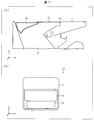
- FIG. 3 is a top view of the louver 10.
- 4 is a cross-sectional view taken along line AA in FIG.
- FIG. 5 is a view of the louver 10 as viewed from the front.
- the drive unit 20 is shown together.
- the louver 10 includes a frame portion 11, a first slide portion (first moving portion) 12, and a second slide portion (second moving portion) 13.
- the frame portion 11 is a housing that forms the outer portion of the louver 10 and supports the first slide portion 12 and the second slide portion 13 inside.
- the louver 10 is fixed to the housing 2 by connecting the frame portion 11 to the upper portion of the housing 2.
- the frame portion 11 is provided with an opening portion 11 a penetrating in the vertical direction.
- the opening part 11a is formed so that the space
- the 1st slide part 12 is a member for adjusting the blowing direction of the air which blows off from humidification air cleaner 1A.
- the first slide portion 12 includes an upper portion 12a, a first projecting surface (first surface) 12b, and a second projecting surface (second surface) 12c. Arranged inside.
- the first slide portion 12 has a hollow inside and is reduced in weight. The first slide portion 12 can be moved horizontally in the front-rear direction (X-axis direction) inside the opening portion 11a by the drive unit 20 described later.
- the upper part 12a is mostly a flat plate parallel to the horizontal direction.
- 6 is a cross-sectional view taken along line AA in FIG.
- an engaging portion 12 d that engages with a sixth gear 33 described later is formed on the lower surface of the right end portion of the upper portion 12 a along the front-rear direction.
- an engaging portion 12e that engages with a second gear 23 described later is formed on the lower surface of the left end portion of the upper portion 12a along the front-rear direction.
- the 1st protrusion surface 12b is a surface for blowing off the air which has passed through the ventilation path P diagonally back in the 1st ventilation mode and 3rd ventilation mode which are mentioned later.
- the first projecting surface 12b has an upper end connected to the rear end of the upper portion 12a, and is inclined so as to be directed forward (+ X-axis direction) as it goes downward ( ⁇ Z-axis direction).
- the second projecting surface 12c is a surface for blowing air that has passed through the ventilation path P obliquely forward in the second air blowing mode and the third air blowing mode described later.
- the second projecting surface 12c has an upper end connected to the front end of the upper portion 12a, and in a cross section perpendicular to the left-right direction (Y-axis direction), it moves rearward (-X-axis direction) toward the lower side (-Z-axis direction). It is formed so as to be inclined.
- the second projecting surface 12 c is a curved line in which a cross section perpendicular to the left-right direction (Y-axis direction) is recessed inside the first slide portion 12. The lower end of the second projecting surface 12c is connected to the lower end of the first projecting surface 12b.
- the first slide portion 12 has a substantially triangular cross section perpendicular to the left-right direction (Y-axis direction) due to the upper portion 12a, the first projecting surface 12b, and the second projecting surface 12c.
- the first projecting surface 12b is formed such that the width in the left-right direction is gradually shortened in the downward direction ( ⁇ Z-axis direction) (in other words, from the front side). It looks like an inverted trapezoid when viewed in plan).
- the second projecting surface 12c is also formed so that the width in the left-right direction gradually decreases as it goes downward (in the ⁇ Z-axis direction) (in other words, as viewed from the front. It has an inverted trapezoidal shape when viewed from above.)
- the second slide portion 13 is a member disposed above the first slide portion 12. As shown in FIGS. 3 to 5, most of the second slide portion 13 is a substantially rectangular flat plate 13a. The width in the front-rear direction of the second slide portion 13 is substantially the same as the width in the front-rear direction of the upper portion 12a of the first slide portion. The second slide portion 13 can be horizontally moved in the front-rear direction inside the opening portion 11a by a driving portion 20 described later, independently of the first slide portion 12.
- FIG. 7 is a cross-sectional view taken along line BB in FIG.
- an engaging portion 13b that is provided below the flat plate 13a and engages with a fourth gear 25 described later, and the flat plate 13a and the engaging portion 13b are provided.
- a connecting portion 13c to be connected is formed.
- an engagement portion 13 d that is provided below the flat plate 13 a and engages with an eighth gear 35 described later, and the flat plate 13 a and the engagement portion 13 d are connected.
- a connecting portion 13e is formed.
- the upper surface of the flat plate 13 a is located at the same height as the upper surface of the frame portion 11. That is, the upper surface of the flat plate 13a and the upper surface of the frame part 11 are the same surface. Thereby, the design property of humidification air cleaner 1A is improved.
- the drive unit 20 is a drive mechanism that horizontally moves the first slide unit 12 and the second slide unit 13 of the louver 10 in the front-rear direction.
- the horizontal movement of the first slide portion 12 and the second slide portion 13 is performed by a rack and pinion mechanism.
- the drive unit 20 includes a first motor 21, a first gear 22, a second gear 23, a third gear 24, a fourth gear 25, a second motor 31, a fifth gear 32, and a sixth gear. 33, a seventh gear 34, an eighth gear 35, a first shaft 37, and a second shaft 38.
- the first motor 21, the first gear 22, the second gear 23, the fifth gear 32, the sixth gear 33, and the first shaft 37 serve as a drive unit (first drive unit) that horizontally moves the first slide unit 12.
- the second motor 31, the seventh gear 34, the eighth gear 35, the third gear 24, the fourth gear 25, and the second shaft 38 are a drive unit (second drive unit) that horizontally moves the second slide unit 13. Function as.
- the first motor 21, the first gear 22, the second gear 23, the third gear 24, and the fourth gear 25 are housed inside the motor box 41. However, the upper ends of the second gear 23 and the fourth gear 25 are exposed to the outside of the motor box 41.
- the second motor 31, the fifth gear 32, the sixth gear 33, the seventh gear 34, and the eighth gear 35 are housed inside the motor box 42. However, the upper ends of the sixth gear 33 and the eighth gear 35 are exposed to the outside of the motor box 42.
- the motor box 41 and the motor box 42 are inside the left and right side portions of the frame portion 11 of the louver 10 and below the left and right side portions of the first slide portion 12 and the second slide portion 13 of the louver 10. Is arranged.
- the motor box 41 and the motor box 42 are provided outside the ventilation path P.
- the first projecting surface 12b and the second projecting surface 12c of the first slide portion 12 have a width in the left-right direction that gradually decreases in the downward direction ( ⁇ Z-axis direction). Is formed.
- the motor box 41 is disposed between the left side (+ Y axis direction side) of the frame portion 11 and the first slide portion 12, and the motor box 42 is positioned on the right side ( ⁇ Y axis direction side) of the frame portion 11. )
- the first slide portion 12 can be arranged. As a result, the vertical size of the humidified air cleaner 1A can be reduced.
- the motor box 41 and the motor box 42 are formed with holes into which the first shaft 37 and the second shaft 38 are inserted.
- the first motor 21 is a motor for horizontally moving the first slide portion 12 in the front-rear direction.
- the first motor 21 is connected to the first gear 22 as shown in FIG.
- the first gear 22 is connected to a second gear 23 that engages with an engaging portion 12d formed on the lower left side (+ Y-axis direction side) of the first slide portion 12.
- the first gear 22 is connected to the fifth gear 32 housed in the motor box 42 by the first shaft 37.
- the fifth gear 32 is connected to a sixth gear 33 that engages with an engagement portion 12 d formed on the lower side of the right side ( ⁇ Y-axis direction side) of the first slide portion 12.
- the first gear 22 is first rotated by driving the first motor 21.
- the second gear 23 is rotated by the rotation of the first gear 22.
- a force is applied to the engaging portion 12d of the first slide portion 12 engaged with the second gear 23.
- the fifth gear 32 rotates via the first shaft 37.
- the sixth gear 33 is rotated by the rotation of the fifth gear 32.
- the sixth gear 33 rotates, a force is applied to the engaging portion 12e of the first slide portion 12 engaged with the sixth gear 33.
- the 1st slide part 12 moves horizontally in the front-back direction with the force each applied to the engaging part 12d and the engaging part 12e.
- the second motor 31 is a motor for horizontally moving the second slide portion 13 in the front-rear direction. As shown in FIG. 5, the second motor 31 is connected to the seventh gear 34.
- the seventh gear 34 is connected to an eighth gear 35 that engages with the engaging portion 13 d of the second slide portion 13.
- the seventh gear 34 is connected by the third gear 24 housed in the motor box 41 and the second shaft 38.
- the third gear 24 is connected to a fourth gear 25 that engages with the engaging portion 13 b of the second slide portion 13.
- the seventh gear 34 is first rotated by driving the second motor 31.
- the eighth gear 35 is rotated by the rotation of the seventh gear 34.
- a force is applied to the engaging portion 13 d of the second slide portion 13 that is engaged with the eighth gear 35.
- the third gear 24 rotates via the second shaft 38.
- the fourth gear 25 is rotated by the rotation of the third gear 24.
- the fourth gear 25 rotates, a force is applied to the engaging portion 13 b of the second slide portion 13 that is engaged with the fourth gear 25.
- the 2nd slide part 13 moves horizontally in the front-back direction with the force each applied to the engaging part 13b and the engaging part 13d.
- the humidified air cleaner 1 ⁇ / b> A can operate in three air blowing modes including a first air blowing mode, a second air blowing mode, and a third air blowing mode described below.
- 1st ventilation mode Air is blown off diagonally backward from the 1st blower outlet 2b.
- 2nd ventilation mode It blows off diagonally forward from the 1st blower outlet 2b.
- 3rd ventilation mode Air is blown off diagonally forward and diagonally backward from the 1st blower outlet 2b.
- FIG. 8 is a view for explaining the first air blowing mode of the humidified air cleaner 1A.
- the drive unit 20 is configured so that the front end of the first slide portion 12 and the front end of the second slide portion 13 are in contact with the front portion of the opening portion 11a of the frame portion 11.
- the first slide part 12 and the second slide part 13 are moved.
- the first projecting surface 12b of the first slide portion 12 and the rear portion of the opening portion 11a of the frame portion 11 form an air passage that blows air that has passed through the air passage P obliquely rearward. . That is, in 1st ventilation mode, 1A of humidified air cleaners blows off air toward the back diagonally from the 1st blower outlet 2b.
- the first protruding surface 12b is formed so as to be substantially flush with a portion (region D1 shown in FIG. 8) of the housing 2 that forms the front of the first air outlet 2b. Thereby, the air that has passed through the ventilation path P can be smoothly blown out obliquely rearward.
- the lower end portion of the first projecting surface 12b comes into contact with the frame portion 11. That is, no gap is formed between the lower end portion of the first projecting surface 12 b and the frame portion 11. Thereby, generation
- FIG. 9 is a diagram for explaining the second air blowing mode of the humidified air cleaner 1A.
- the drive unit 20 is configured such that the rear end of the first slide unit 12 and the rear end of the second slide unit 13 are in contact with the rear part of the opening 11 a of the frame unit 11. Moves the first slide part 12 and the second slide part 13. As a result, the second projecting surface 12c of the first slide portion 12 and the front portion of the opening portion 11a of the frame portion 11 form an air passage that blows air that has passed through the air passage P obliquely forward. . That is, in the 2nd ventilation mode, 1A of humidification air cleaners blows off air toward the slanting front from the 1st blower outlet 2b.
- the second projecting surface 12c has a curved shape in which a cross section perpendicular to the left-right direction (Y-axis direction) is recessed inside the first slide portion 12. That is, the second projecting surface 12 c is a curved surface that is recessed inside the first slide portion 12.
- the air which has passed through the ventilation path P can be smoothly blown out obliquely forward.
- 1 A of humidification air cleaners blows off more air. Be able to.
- FIG. 10 is a diagram for explaining a third air blowing mode of the humidified air cleaner 1A.
- the drive unit 20 is positioned in the vicinity of the center in the front-rear direction of the opening 11 a so that the first slide unit 12 and the second slide unit 13 are located in the first slide unit 12. And the 2nd slide part 13 is moved. Thereby, while the 1st protrusion surface 12b of the 1st slide part 12 and the rear part of the opening part 11a of the frame part 11, the air path which blows off the air which passed the ventilation path P toward diagonally backward is formed.
- the second projecting surface 12c of the first slide portion 12 and the front portion of the opening portion 11a of the frame portion 11 form an air passage that blows air that has passed through the air passage P obliquely forward. That is, in the second air blowing mode, the humidified air cleaner 1A blows out air from the first air outlet 2b diagonally forward and diagonally backward.
- the first projecting surface 12b and the second projecting surface 12c are connected to each other at the lower end, and have a shape in which the connection portion projects downward ( ⁇ Z direction).
- the connection portion projects downward ( ⁇ Z direction).
- the louver 10 in the present embodiment is a louver that is provided in the first air outlet 2b of the ventilation path P of the humidified air purifier 1A and controls the air blowing direction from the first air outlet 2b.
- the louver 10 includes a frame portion 11 in which an opening 11a is formed, and a first slide portion 12 provided inside the frame portion 11 and movable in one direction (front-rear direction).
- the first slide part 12 has a first projecting surface 12b and a second projecting surface 12c arranged in the front-rear direction, and the first projecting surface 12b and the second projecting surface 12c are first projecting toward the ventilation path P.
- the distance between the surface 12b and the second projecting surface 12c is formed to be small.
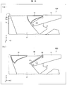
- FIG. 11 is a view for explaining a stop mode of the humidified air cleaner 1A
- (a) is a cross-sectional view of the humidified air cleaner 1A obtained by cutting the humidified air cleaner 1A near the center in the left-right direction
- (B) is the figure which looked at the humidified air cleaner 1A from the upper direction.
- the rear end of the first slide portion 12 contacts the rear portion of the opening portion 11 a of the frame portion 11 and the front end of the second slide portion 13.
- the drive part 20 moves the first slide part 12 and the second slide part 13 so that the contact part contacts the front part of the opening part 11a of the frame part 11.
- the opening 11 a of the frame 11 can be covered (closed) by the first slide portion 12 and the second slide portion 13.
- the first slide portion 12 and the second slide portion 13 are moved by the rack and pinion mechanism.
- the present invention is not limited to this, and the first slide portion 12 and the second slide portion 13 are moved in the horizontal direction. Any mechanism may be used as long as the mechanism can be moved to the position.
- the air blower of one aspect of the present invention may be configured such that the first slide portion 12 and the second slide portion 13 are horizontally moved by a crank mechanism.
- the humidified air cleaner 1A has been described as the blower, but the blower of the present invention is not limited to this.
- a blower can be a fan heater (device that warms room air), an ion generator (device that adjusts the ion balance in the room), an air purifier (device that cleans the room air), a dehumidifier (room It may be a blower such as a device that reduces the humidity of air) or a humidifier (device that increases the humidity of air in the room).
- the first projecting surface 12b has a substantially planar shape, but the louver of the present invention is not limited to this.
- the first projecting surface 12 b may be a curve in which a cross section perpendicular to the left-right direction (Y-axis direction) is recessed inside the first slide portion 12. According to said structure, in 1st ventilation mode and 2nd ventilation mode, air can be blown out back from 1 A of humidification air cleaners.
- the louver of the present invention is not limited to this.
- the first slide portion has a configuration in which the lower end of the first projecting surface 12b and the lower end of the second projecting surface 12c are connected by, for example, a flat plate (that is, the left-right direction (Y-axis direction).
- a flat plate that is, the left-right direction (Y-axis direction
- the configuration in which the cross section perpendicular to) is an inverted trapezoidal shape may be used.
- the opening portion 11a of the frame portion 11 is covered by the first slide portion 12 and the second slide portion 13 in the stop mode.
- the louver 10 ⁇ / b> A according to the present embodiment includes a lid portion 50 instead of the second slide portion 13.
- the louver 10 ⁇ / b> A includes a lid 50.
- the lid portion 50 includes a flat plate 51 and a rotating portion 52 that rotates the flat plate 51 around the rear portion of the opening portion 11a of the frame portion 11.
- the flat plate 51 is supported by a support mechanism (not shown) so as to be parallel to the horizontal direction. Furthermore, the front end of the first slide portion 12 is positioned so as to contact the front portion of the opening portion 11 a of the frame portion 11. Thereby, in the stop mode, the opening 11 a of the frame portion 11 can be covered (closed) by the first slide portion 12 and the flat plate 51. As a result, in the stop mode, it is possible to prevent foreign matters such as dust from entering the inside of the housing 2 and the inside of the louver 10.
- FIG. 13A is a cross-sectional view showing a configuration of a louver 10B as a modification of the louver 10A in the second embodiment
- FIG. 13B is a cross-sectional view showing a configuration of a louver 10C as a modification of the louver 10A. is there.
- the louver 10C includes a lid 60.
- the lid portion 60 includes a flat plate 61 and a rotating portion 62 that rotates the flat plate 61 around the front portion of the opening 11 a of the frame portion 11.
- the flat plate 61 is supported in parallel with the horizontal direction by a support mechanism (not shown). Further, the rear end of the first slide part 12 is positioned so as to contact the rear part of the opening part 11 a of the frame part 11. Thereby, in the stop mode, the opening 11a of the frame portion 11 can be covered (closed) by the first slide portion 12 and the flat plate 61. As a result, in the stop mode, it is possible to prevent foreign matters such as dust from entering the inside of the housing 2 and the inside of the louver 10.
- the rotating portion 62 faces the ventilation path P so that the flat plate 61 is parallel to the front portion of the opening portion 11 a of the frame portion 11. Rotate. Thereby, when 1 A of humidification air cleaners are in ventilation mode, the flat plate 61 does not become resistance of ventilation.
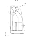
- FIG. 14 is a cross-sectional view of the humidified air cleaner 1B obtained by cutting the humidified air cleaner 1B according to the present embodiment near the center in the left-right direction.
- the humidified air cleaner 1 ⁇ / b> B in the present embodiment includes an ion generator 6 in addition to the configuration of the humidified air cleaner 1 ⁇ / b> A in the first embodiment.
- the humidified air cleaner 1B includes a damper 7A instead of the damper 7 in the first embodiment.
- the ion generator 6 includes positive ions H + (H 2 O) m (m is an arbitrary natural number) and negative ions O 2 ⁇ (H 2 ), which are ions in which water molecules gather in the air flowing through the ventilation path P. O) n (n is an arbitrary natural number) is released.
- the ion generator 6 includes a discharge electrode 6a and an induction electrode 6b exposed to the ventilation path P, and generates a corona discharge when a high voltage is applied to the discharge electrode and the induction electrode to generate the ions. Is done. It is known that the ions have a sterilizing effect, a deodorizing effect, a virus action suppressing effect, and a static electricity suppressing effect. In addition, the ion generator 6 is not restricted to what produces
- the ion generator 6 of one embodiment of the present invention may emit positive and negative ions other than the above ions or negative ions.
- a brush 7a is provided at the tip of the damper 7A.
- the brush 7a comes into contact with the discharge electrode 6a and the induction electrode 6b of the ion generator 6 and removes dirt (for example, silicon) attached to the discharge electrode 6a and the induction electrode 6b. to clean up.
- dirt for example, silicon
- damper 7A was the aspect attached to the upper part of the opening part by the side of the housing
- the air blower of this invention is not restricted to this.
- the damper 7 ⁇ / b> A may be attached to the lower end portion of the louver 10.
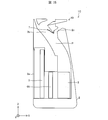
- FIG. 15 is a cross-sectional view of the humidified air cleaner 1C obtained by cutting the humidified air cleaner 1C according to the present embodiment near the center in the left-right direction.
- the humidified air cleaner 1 ⁇ / b> C includes a humidified filter unit 4 ⁇ / b> A instead of the humidified filter unit 4 of the humidified air cleaner 1 ⁇ / b> A in the first embodiment.
- FIG. 16 shows the configuration of the humidifying filter unit 4A, and is a cross-sectional view cut along a cross section perpendicular to the X-axis direction.
- the humidifying filter unit 4A includes a holding frame 4a, a rail 4b, and a humidifying filter (filter member) 4c.
- the holding frame 4a has a hollow disk shape, and stores and holds the rail 4b and the humidifying filter 4c inside.
- the rail 4b is made of resin and is housed inside the holding frame 4a.
- the rail 4b has a spiral shape (spiral shape) in a cross section perpendicular to the direction (X-axis direction) in which the air that has passed through the HEPA filter 3 travels to the humidifying filter unit 4.
- the humidifying filter 4c is formed in a flat plate shape by folding a sheet made of a material that has water absorption properties such as rayon and can be ventilated into a bellows shape, and is housed inside the holding frame 4a.
- the lower part of the humidifying filter unit 4A is immersed in a water tank (not shown) and is rotated by a rotation mechanism (not shown).
- the humidifying filter unit 4A includes a spiral rail 4b. Accordingly, when the humidifying filter unit 4A is rotated by the rotating mechanism, the water stored in the water tank is transported to the central portion of the humidifying filter unit 4A along the spiral rail 4b. As a result, water can be sufficiently supplied to the humidifying filter 4c near the center. Therefore, the humidified air cleaner 1 ⁇ / b> C can blow out air containing much moisture as compared with the conventional humidified air cleaner.
- louvers (10 ⁇ 10A to 10C) are provided at the air outlet (first air outlet 2b) of the ventilation path (P) of the blower (humidified air cleaners 1A to 1C).
- a louver that controls the direction in which air is blown from the outlet and is a frame portion (11) having an opening (11a) formed therein, and a first moving portion that is provided inside the frame portion and is movable in one direction.
- First slide portion 12 and the first moving portion has a first surface (first projecting surface 12b) and a second surface (second projecting surface 12c) arranged in the one direction, The first surface and the second surface are formed such that a distance between the first surface and the second surface becomes smaller toward the ventilation path.
- a 1st moving part moves to the position where a 1st surface contact
- a 1st air path is formed between a 2nd surface and a frame part.
- a second air path different from the first air path is formed between the first surface and the frame part. Is done.
- the first moving body moves to the center part of the frame part
- the first air path and the second air path are formed. That is, by moving the first moving unit, air can be blown out from only one of the first air passage and the second air passage, and air can be blown out from both the first air passage and the second air passage. it can. That is, with a simple configuration, air can be blown out from the blower device in different directions.
- the first surface and the second surface have a configuration in which end portions on the ventilation path side are connected to each other.
- the first moving part has a shape protruding toward the ventilation path side. Therefore, when the air which passed the ventilation path reaches
- the louver according to aspect 3 of the present invention is the configuration according to aspect 1 or 2, wherein at least one of the first surface and the second surface is a curved surface recessed inward of the first moving unit. Also good.
- the air that has passed through the ventilation path can be smoothly blown obliquely forward. Moreover, since the distance between the 1st surface or the 2nd surface and the opening part of a frame part can be enlarged, an air blower can blow off more air.
- the air blower according to aspect 4 of the present invention includes the louver according to any one of aspects 1 to 3.
- the louver further includes a second moving part (second slide part 13) that is movable in the one direction independently of the first moving part. And the first moving unit and the second moving unit cover the air outlet in a stopped state of the blower.
- the air blower according to aspect 6 of the present invention is the air blower according to aspect 5 described above, wherein the first drive unit (the first motor 21, the first gear 22, the second gear 23, the fifth gear 32, the first gear, and the like) moves the first moving unit. 6 gear 33, first shaft 37) and a second drive unit (second motor 31, seventh gear 34, eighth gear 35, third gear 24, fourth gear 25, second gear) for moving the second moving unit. 2 shafts 38).
- first drive unit the first motor 21, the first gear 22, the second gear 23, the fifth gear 32, the first gear, and the like
- 6 gear 33, first shaft 37 and a second drive unit (second motor 31, seventh gear 34, eighth gear 35, third gear 24, fourth gear 25, second gear) for moving the second moving unit. 2 shafts 38).
- the air blower according to aspect 7 of the present invention is the air conditioner according to aspect 6, in which the first drive unit is located at both ends of the first moving unit on a plane perpendicular to the one direction with respect to the first moving unit. It is preferable that the force be applied.
- the first moving unit can be smoothly moved horizontally.
Landscapes
- Engineering & Computer Science (AREA)
- Chemical & Material Sciences (AREA)
- Combustion & Propulsion (AREA)
- Mechanical Engineering (AREA)
- General Engineering & Computer Science (AREA)
- Air-Flow Control Members (AREA)
- Air Conditioning Control Device (AREA)
Abstract
簡素な構成で、送風装置から互いに異なる方向に空気を吹き出させる。ルーバー(10)は、開口部(11a)が形成された枠部(11)と、前後方向に移動可能な第1スライド部(12)を備え、な第1スライド部(12)は、第1突出面(12b)および第2突出面(12c)を有しており、下方に向かうにつれて第1突出面(12b)と第2突出面(12c)との距離が小さくなるように形成されている
Description
本発明は、ルーバーおよび当該ルーバーを備える送風装置に関する。
空気清浄器などの送風装置は、送風装置が設置された部屋内の空気を効率良く循環させるために、空気を吹き出す方向を規定するルーバー(風向板)を備えている。
例えば、特許文献1に記載の空気清浄器は、吹出口に吹出空気を複数の吹出空気に分けるルーバーを備えている。ルーバーは、仕切羽根と、第1風向調整羽根と、第2風向調整羽根とを有している。仕切羽根は、吹出口を、第1の吹出空気が通過する領域と第2の吹出空気が通過する領域とに仕切る。第1風向調整羽根は、第1の吹出空気を第1方向に向かわせ、第2風向調整羽根は、第1の吹出空気を第2方向に向かわせる。第1風向調整羽根及び第2風向調整羽根は、仕切羽根と交差し、且つ鉛直方向に対して傾斜自在に仕切羽根に支持されている。上記の構成により、複数の方向へ空気を吹き出すことができるようになっている。
しかしながら、特許文献1に記載のルーバーでは、複数の方向へ空気を吹き出すことができるが、そのためにルーバーの構成が複雑なものとなっている。
本発明の一態様は、簡素な構成で、送風装置から互いに異なる方向に空気を吹き出させることができるルーバーを実現することを目的とする。
上記の課題を解決するために、本発明の一態様に係るルーバーは、送風装置の通風路の吹出口に備えられ、前記吹出口からの空気の吹出方向を制御するルーバーであって、開口部が形成された枠部と、前記枠部の内部に設けられ、一方向に移動可能な第1移動部とを備え、前記第1移動部は、前記一方向において並ぶ第1面および第2面を有しており、前記第1面および前記第2面は、前記通風路に向かうにつれて前記第1面と前記第2面との距離が小さくなるように形成されている。
本発明の一態様によれば、簡素な構成で、送風装置から互いに異なる方向に空気を吹き出させることができるという効果を奏する。
〔実施形態1〕
以下、本発明の実施形態1におけるルーバー10および送風装置としての加湿空気清浄器1Aについて、図面を参照しながら詳細に説明する。
以下、本発明の実施形態1におけるルーバー10および送風装置としての加湿空気清浄器1Aについて、図面を参照しながら詳細に説明する。
図1は、加湿空気清浄器1Aの外観を示す斜視図である。図2は、加湿空気清浄器1Aを左右方向の中央付近で切断した加湿空気清浄器1Aの断面図である。なお、以降では、加湿空気清浄器1Aの前方向を+X方向、後方向を-X方向、左方向を+Y方向、右方向を-Y方向、上方向を+Z方向、下方向を-Z方向をとして説明する。
図1および図2に示すように、加湿空気清浄器1Aは、筐体2と、HEPAフィルタ(High-Efficiency Particulate Airフィルタ)3と、加湿フィルタユニット4と、ファン5と、ダンパー7と、ルーバー10と、駆動部20とを備えている。
筐体2は、加湿空気清浄器1Aの各部を収納する。筐体2は、上下方向に垂直な断面が略矩形となっており、上方向に向かうにつれて断面積が小さくなっている。筐体2の背面には、空気を取り込むための吸入口2aが設けられている。
HEPAフィルタ3は、吸入口2aから筐体2の内部に取り込まれた空気に含まれる微細な塵埃を捕集、除去するための集塵フィルタである。HEPAフィルタ3は、従来のHEPAフィルタを用いることができるため、詳細な説明は省略する。
加湿フィルタユニット4は、HEPAフィルタ3を通過した空気に水分を供給するためのフィルタである。加湿フィルタユニット4は、従来の加湿フィルタユニットを用いることができるため、詳細な説明は省略する。
ファン5は、吸入口2aから空気を吸入し、吸入した空気を外部へ吹き出させるためのファンである。ファン5は、従来のファンを用いることができるため、詳細な説明は省略する。
筐体2の内部には、ファン5から上方に向かって通風路Pが形成されている。より詳細には、通風路Pは、ファン5から上方に向かうにつれて後方(-X軸方向)に向かうように傾斜して形成されている。
また、筐体2は、第1吹出口(吹出口)2bと、第2吹出口2cとの2つの吹出口を備えている。
第1吹出口2bは、筐体2の上部から通風路Pを通過してきた空気が吹き出される吹出口である。第2吹出口2cは、筐体2の前方の側面から通風路Pを通過してきた空気が吹き出される吹出口である。
ダンパー7は、第2吹出口2cの筐体2側の開口部の上部に取り付けられており、図示しないステッピングモータにより取付位置を軸として回転する。ダンパー7が第2吹出口2cの筐体2側の開口部を塞ぐ位置にある場合では第2吹出口から空気が吹き出されない。また、ダンパー7が第2吹出口2cの筐体2側の開口部を塞ぐ位置にない場合(例えば、図2に示す状態)では第2吹出口2cから空気が吹き出される。このように、加湿空気清浄器1Aでは、ダンパー7を移動させることによって、後述する第1~3送風モードによる送風に加えて、前方に空気を吹き出すことができるようになっている。
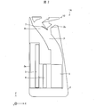
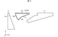
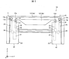
ルーバー10は、加湿空気清浄器1Aから空気が吹き出される位置に配置され、加湿空気清浄器1Aから吹き出される空気の吹き出し方向を調整するための風向板である。以下に、ルーバー10の詳細な構造について図面を参照しながら説明する。図3は、ルーバー10の上面図である。図4は、図3におけるA-A線矢視断面図である。図5は、ルーバー10を前方から見た図である。なお、図5では、ルーバー10に加えて駆動部20を合わせて図示している。
図3~図5に示すように、ルーバー10は、枠部11と、第1スライド部(第1移動部)12と、第2スライド部(第2移動部)13とを備えている。
枠部11は、ルーバー10の外側部を構成する筐体であり、第1スライド部12および第2スライド部13を内部で支持している。ルーバー10は、図1に示すように、枠部11が筐体2の上部に接続されることにより筐体2に固定されている。枠部11は、図4に示すように、上下方向に貫通する開口部11aが設けられている。開口部11aは、上方に向かうにつれて前後方向の間隔が大きくなるように形成されている。すなわち、開口部11aのうち前方部分は上方に向かうにつれて前方向に向かうように傾斜しており、開口部11aのうち後方部分は上方に向かうにつれて後方向に向かうように傾斜している。
第1スライド部12は、加湿空気清浄器1Aから吹き出される空気の吹き出し方向を調整するための部材である。第1スライド部12は、図4に示すように、上部12aと、第1突出面(第1面)12bと、第2突出面(第2面)12cとを備えており、開口部11aの内部に配置されている。第1スライド部12は、内部が空洞となっており、軽量化されている。第1スライド部12は、後述する駆動部20によって開口部11aの内部において前後方向(X軸方向)に水平移動できるようになっている。
上部12aは、大部分が水平方向に平行な平板となっている。図6は、図5におけるA-A線矢視断面図である。図5および図6に示すように、上部12aの右側の端部の下面には、後述する第6ギア33と係合する係合部12dが前後方向に沿って形成されている。同様に、上部12aの左側の端部の下面には、後述する第2ギア23と係合する係合部12eが前後方向に沿って形成されている。
第1突出面12bは、後述する第1送風モードおよび第3送風モードにおいて、通風路Pを通過してきた空気を斜め後方へ向けて吹き出させるための面である。第1突出面12bは、上端が上部12aの後端と接続しており、下方(-Z軸方向)に向かうにつれて前方(+X軸方向)に向かうように傾斜して形成されている。
第2突出面12cは、後述する第2送風モードおよび第3送風モードにおいて、通風路Pを通過してきた空気を斜め前方へ向けて吹き出させるための面である。第2突出面12cは、上端が上部12aの前端と接続しており、左右方向(Y軸方向)に垂直な断面において、下方(-Z軸方向)に向かうにつれて後方(-X軸方向)に向かうように傾斜して形成されている。また、第2突出面12cは、左右方向(Y軸方向)に垂直な断面が第1スライド部12の内側に凹んだ曲線となっている。第2突出面12cの下端は、第1突出面12bの下端と接続されている。
以上のように、第1スライド部12は、上部12a、第1突出面12b、および第2突出面12cによって、左右方向(Y軸方向)に垂直な断面が略三角形状となっている。
また、第1突出面12bは、図5に示すように、下方向(-Z軸方向)に向かうにつれて、左右方向の幅が徐々に短くなるように形成されている(換言すれば、正面から見た平面視したときに逆台形状になっている)。図示していないが、第2突出面12cも同様に、下方向(-Z軸方向)に向かうにつれて、左右方向の幅が徐々に短くなるように形成されている(換言すれば、正面から見た平面視したときに逆台形状になっている)。
第2スライド部13は、第1スライド部12よりも上方に配置される部材である。第2スライド部13は、図3~5に示すように、大部分が略矩形状の平板13aからなっている。第2スライド部13の前後方向の幅は、第1スライド部の上部12aの前後方向の幅と略同じ大きさとなっている。第2スライド部13は、第1スライド部12とは独立して、後述する駆動部20によって開口部11aの内部において前後方向に水平移動できるようになっている。
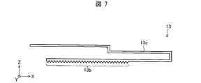
図7は、図5におけるB-B線矢視断面図である。図7に示すように、第2スライド部13の左端には、平板13aの下方に設けられ、後述する第4ギア25と係合する係合部13bと、平板13aと係合部13bとを接続する接続部13cとが形成されている。また、同様に、第2スライド部13の右端には、平板13aの下方に設けられ、後述する第8ギア35と係合する係合部13dと、平板13aと係合部13dとを接続する接続部13eが形成されている。
平板13aの上面は、枠部11の上面と同じ高さに位置している。すなわち、平板13aの上面と、枠部11の上面とは同一面になっている。これにより、加湿空気清浄器1Aのデザイン性を向上させている。
駆動部20は、ルーバー10の第1スライド部12および第2スライド部13を前後方向に水平移動させる駆動機構である。本実施形態では、第1スライド部12および第2スライド部13の水平移動は、ラックアンドピニオン機構で行われる。
駆動部20は、図5に示すように、第1モータ21、第1ギア22、第2ギア23、第3ギア24、第4ギア25、第2モータ31、第5ギア32、第6ギア33、第7ギア34、第8ギア35、第1シャフト37、および第2シャフト38を備えている。
第1モータ21、第1ギア22、第2ギア23、第5ギア32、第6ギア33、および第1シャフト37は、第1スライド部12を水平移動させる駆動部(第1駆動部)として機能する。また、第2モータ31、第7ギア34、第8ギア35、第3ギア24、第4ギア25、第2シャフト38は、第2スライド部13を水平移動させる駆動部(第2駆動部)として機能する。
第1モータ21、第1ギア22、第2ギア23、第3ギア24、および第4ギア25は、モータボックス41の内部に収納されている。ただし、第2ギア23および第4ギア25の上端部は、モータボックス41の外部に露出されている。また、第2モータ31、第5ギア32、第6ギア33、第7ギア34、および第8ギア35は、モータボックス42の内部に収納されている。ただし、第6ギア33および第8ギア35の上端部は、モータボックス42の外部に露出されている。
モータボックス41およびモータボックス42は、ルーバー10の枠部11の左右方向の側部の内側であり、かつ、ルーバー10の第1スライド部12および第2スライド部13の左右方向の側部の下方に配置されている。また、モータボックス41およびモータボックス42は、通風路Pの外側に設けられている。ここで、上述したように、第1スライド部12の第1突出面12bおよび第2突出面12cは、下方向(-Z軸方向)に向かうにつれて、左右方向の幅が徐々に短くなるように形成されている。これにより、モータボックス41を枠部11の左側(+Y軸方向側)の側部と第1スライド部12との間に配置するとともに、モータボックス42を枠部11の右側(-Y軸方向側)の側部と第1スライド部12との間に配置することができるようになっている。その結果、加湿空気清浄器1Aの上下方向のサイズを小型化することができるようになっている。
なお、モータボックス41およびモータボックス42には、第1シャフト37および第2シャフト38が挿入される孔が形成されている。
第1モータ21は、第1スライド部12を前後方向に水平移動させるためのモータである。第1モータ21は、図5に示すように、第1ギア22と接続されている。第1ギア22は、第1スライド部12の左側(+Y軸方向側)の下側に形成された係合部12dと係合する第2ギア23と接続されている。また、第1ギア22は、モータボックス42に収納されている第5ギア32と第1シャフト37により連結されている。第5ギア32は、第1スライド部12の右側(-Y軸方向側)の下側に形成された係合部12dと係合する第6ギア33と接続されている。
上記の構成により、第1モータ21を駆動させることにより、まず、第1ギア22が回転する。次に、第1ギア22の回転により第2ギア23が回転する。第2ギア23が回転すると、第2ギア23と係合されている第1スライド部12の係合部12dに力が印加される。また、第2ギア23が回転することにより、第1シャフト37を介して第5ギア32が回転する。次に、第5ギア32の回転により第6ギア33が回転する。第6ギア33が回転すると、第6ギア33と係合されている第1スライド部12の係合部12eに力が印加される。そして、係合部12dおよび係合部12eにそれぞれ印加された力によって、第1スライド部12が前後方向に水平移動するようになっている。以上のように、本実施形態では、第1スライド部12の左右方向の両端部において、第1スライド部12に力が印加されるようになっている。その結果、第1スライド部12が左右方向に長く形成されている場合においても、第1スライド部12をスムーズに水平移動させることができるようになっている。
第2モータ31は、第2スライド部13を前後方向に水平移動させるためのモータである。第2モータ31は、図5に示すように、第7ギア34と接続されている。第7ギア34は、第2スライド部13の係合部13dと係合する第8ギア35と接続されている。また、第7ギア34は、モータボックス41に収納されている第3ギア24と第2シャフト38とにより連結されている。第3ギア24は、第2スライド部13の係合部13bと係合する第4ギア25と接続されている。
上記の構成により、第2モータ31を駆動させることにより、まず、第7ギア34が回転する。次に、第7ギア34の回転により第8ギア35が回転する。第8ギア35が回転すると、第8ギア35と係合されている第2スライド部13の係合部13dに力が印加される。また、第7ギア34が回転することにより、第2シャフト38を介して第3ギア24が回転する。次に、第3ギア24の回転により第4ギア25が回転する。第4ギア25が回転すると、第4ギア25と係合されている第2スライド部13の係合部13bに力が印加される。そして、係合部13bおよび係合部13dにそれぞれ印加された力によって、第2スライド部13が前後方向に水平移動するようになっている。以上のように、本実施形態では、第2スライド部13の左右方向の両端部において、第2スライド部13に力が印加されるようになっている。その結果、第2スライド部13が左右方向に長く形成されている場合においても、第2スライド部13をスムーズに水平移動させることができるようになっている。
次に、加湿空気清浄器1Aの送風モードについて説明する。加湿空気清浄器1Aは、以下に示す第1送風モード、第2送風モードおよび第3送風モードの3つの送風モードで動作することができる。
第1送風モード:第1吹出口2bから斜め後方へ向けて空気を吹き出す。
第2送風モード:第1吹出口2bから斜め前方へ向けて吹き出す。
第3送風モード:第1吹出口2bから斜め前方および斜め後方へ向けて空気を吹き出す。
第1送風モード:第1吹出口2bから斜め後方へ向けて空気を吹き出す。
第2送風モード:第1吹出口2bから斜め前方へ向けて吹き出す。
第3送風モード:第1吹出口2bから斜め前方および斜め後方へ向けて空気を吹き出す。
以下に、それぞれに送風モードについて詳細に説明する。
(第1送風モード)
第1送風モードについて、図8を参照しながら説明する。図8は、加湿空気清浄器1Aの第1送風モードを説明するための図である。
第1送風モードについて、図8を参照しながら説明する。図8は、加湿空気清浄器1Aの第1送風モードを説明するための図である。
図8に示すように、第1送風モードでは、第1スライド部12の前端および第2スライド部13の前端が枠部11の開口部11aの前方部分に当接するように、駆動部20が第1スライド部12および第2スライド部13を移動させる。これにより、第1スライド部12の第1突出面12bと、枠部11の開口部11aの後方部分とによって、通風路Pを通過してきた空気を斜め後方へ向けて吹き出す風路が形成される。すなわち、第1送風モードでは、加湿空気清浄器1Aは、第1吹出口2bから斜め後方へ向けて空気を吹き出す。
第1突出面12bは、筐体2のうち第1吹出口2bの前方を形成する部分(図8に示す領域D1)と略同一面となるように形成されている。これにより、通風路Pを通過してきた空気をスムーズに斜め後方へ向けて吹き出すことができるようになっている。
また、第1スライド部12が上記の位置にあるとき、第1突出面12bの下端部が枠部11と当接するようになっている。すなわち、第1突出面12bの下端部と、枠部11との間に隙間が形成されないようになっている。これにより、乱流が発生することを抑制することができる。その結果、異音が発生することを防ぐことができるようになっている。
(第2送風モード)
第2送風モードについて、図9を参照しながら説明する。図9は、加湿空気清浄器1Aの第2送風モードを説明するための図である。
第2送風モードについて、図9を参照しながら説明する。図9は、加湿空気清浄器1Aの第2送風モードを説明するための図である。
図9に示すように、第2送風モードでは、第1スライド部12の後端および第2スライド部13の後端が枠部11の開口部11aの後方部分に当接するように、駆動部20が第1スライド部12および第2スライド部13を移動させる。これにより、第1スライド部12の第2突出面12cと、枠部11の開口部11aの前方部分とによって、通風路Pを通過してきた空気を斜め前方へ向けて吹き出す風路が形成される。すなわち、第2送風モードでは、加湿空気清浄器1Aは、第1吹出口2bから斜め前方へ向けて空気を吹き出す。
上述したように、第2突出面12cは、左右方向(Y軸方向)に垂直な断面が第1スライド部12の内側に凹んだ曲線となっている。すなわち、第2突出面12cは、第1スライド部12の内側に凹んだ曲面となっている。これにより、通風路Pを通過してきた空気をスムーズに斜め前方へ向けて吹き出すことができるようになっている。また、第1スライド部12の第2突出面12cと、枠部11の開口部11aの前方部分との間の距離を大きくすることができるので、加湿空気清浄器1Aがより多くの空気を吹き出すことができるようになっている。
(第3送風モード)
第3送風モードについて、図10を参照しながら説明する。図10は、加湿空気清浄器1Aの第3送風モードを説明するための図である。
第3送風モードについて、図10を参照しながら説明する。図10は、加湿空気清浄器1Aの第3送風モードを説明するための図である。
図10に示すように、第3送風モードでは、第1スライド部12および第2スライド部13が、開口部11aの前後方向の中央付近に位置するように、駆動部20が第1スライド部12および第2スライド部13を移動させる。これにより、第1スライド部12の第1突出面12bと枠部11の開口部11aの後方部分とによって、通風路Pを通過してきた空気を斜め後方へ向けて吹き出す風路が形成されるとともに、第1スライド部12の第2突出面12cと枠部11の開口部11aの前方部分とによって、通風路Pを通過してきた空気を斜め前方へ向けて吹き出す風路が形成される。すなわち、第2送風モードでは、加湿空気清浄器1Aは、第1吹出口2bから斜め前方および斜め後方へ向けて空気を吹き出す。
上述したように、第1突出面12bと第2突出面12cとは、下端において互いに接続されており、接続箇所が下方向(-Z方向)に向けて突き出した形状となっている。これにより、通風路Pを通過してきた空気が上記接続箇所に到達した際に、上記接続箇所が抵抗にならないようになっている。これにより、加湿空気清浄器1Aは、空気の速度を低下させることなく、空気を吹き出すことができるようになっている。
以上のように、本実施形態におけるルーバー10は、加湿空気清浄器1Aの通風路Pの第1吹出口2bに備えられ、第1吹出口2bからの空気の吹出方向を制御するルーバーである。ルーバー10は、開口部11aが形成された枠部11と、枠部11の内部に設けられ、一方向(前後方向)に移動可能な第1スライド部12とを備える。第1スライド部12は、前後方向において並ぶ第1突出面12bおよび第2突出面12cを有しており、第1突出面12bおよび第2突出面12cは、通風路Pに向かうにつれて第1突出面12bと第2突出面12cとの距離が小さくなるように形成されている。
上記の構成によれば、第1スライド部12を移動させることによって、第1吹出口2bから斜め後方または斜め前方に空気を吹き出すことができるとともに、第1吹出口2bから斜め前方および斜め後方へ向けて空気を吹き出すことができる。すなわち、簡素な構成で、加湿空気清浄器1Aから互いに異なる方向に空気を吹き出させることができる。
(停止モード)
次に、加湿空気清浄器1Aの運転が停止していない状態(以降では、停止モードとも呼称する)について、図11を参照しながら説明する。図11は、加湿空気清浄器1Aの停止モードを説明するためのものであり、(a)は加湿空気清浄器1Aを左右方向の中央付近で切断した加湿空気清浄器1Aの断面図であり、(b)は加湿空気清浄器1Aを上方から見た図である。
次に、加湿空気清浄器1Aの運転が停止していない状態(以降では、停止モードとも呼称する)について、図11を参照しながら説明する。図11は、加湿空気清浄器1Aの停止モードを説明するためのものであり、(a)は加湿空気清浄器1Aを左右方向の中央付近で切断した加湿空気清浄器1Aの断面図であり、(b)は加湿空気清浄器1Aを上方から見た図である。
図11の(a)および(b)に示すように、停止モードでは、第1スライド部12の後端が枠部11の開口部11aの後方部分に当接するとともに、第2スライド部13の前端が枠部11の開口部11aの前方部分に当接するように、駆動部20が第1スライド部12および第2スライド部13を移動させる。これにより、停止モードにおいて、第1スライド部12および第2スライド部13によって、枠部11の開口部11aを覆う(塞ぐ)ことができる。その結果、停止モードにおいて、筐体2の内部およびルーバー10の内部に埃などの異物が混入することを防ぐことができるようになっている。
なお、本実施形態では、第1スライド部12および第2スライド部13をラックアンドピニオン機構により移動させる形態であったがこれに限られず、第1スライド部12および第2スライド部13を水平方向に移動させることができる機構であればどのような機構であってもよい。例えば、本発明の一態様の送風装置では、クランク機構によって第1スライド部12および第2スライド部13を水平移動させる形態であってもよい。
また、本実施形態では、送風装置として加湿空気清浄器1Aを説明したが、本発明の送風装置はこれに限られない。例えば、送風装置は、ファンヒーター(部屋の空気を温める機器)、イオン発生機(部屋のイオンバランスを調整する機器)、空気清浄器(部屋の空気の清浄を行う機器)、除湿器(部屋の空気の湿度を低減する機器)、加湿器(部屋の空気の湿度を増加させる機器)などの送風装置であってもよい。
なお、本実施形態では、第1突出面12bは略平面形状となっていたが、本発明のルーバーはこれに限られない。すなわち、第1突出面12bは、左右方向(Y軸方向)に垂直な断面が第1スライド部12の内側に凹んだ曲線となっていてもよい。上記の構成によれば、第1送風モードおよび第2送風モードにおいて、加湿空気清浄器1Aからより後方に空気を吹き出させることができる。
また、本実施形態では、第1突出面12bの下端と第2突出面12cの下端とが接続されていることにより、第1スライド部12が左右方向(Y軸方向)に垂直な断面が略三角形状となっている態様であったが、本発明のルーバーはこれに限られない。本発明の一態様のルーバーでは、第1スライド部が、第1突出面12bの下端と第2突出面12cの下端とが例えば平板などによって接続されている構成(すなわち、左右方向(Y軸方向)に垂直な断面が逆台形状である構成)であってもよい。
〔実施形態2〕
本発明の他の実施形態について、図12に基づいて説明すれば、以下のとおりである。なお、説明の便宜上、前記実施形態にて説明した部材と同じ機能を有する部材については、同じ符号を付記し、その説明を省略する。
本発明の他の実施形態について、図12に基づいて説明すれば、以下のとおりである。なお、説明の便宜上、前記実施形態にて説明した部材と同じ機能を有する部材については、同じ符号を付記し、その説明を省略する。
実施形態1におけるルーバー10では、停止モードにおいて、第1スライド部12および第2スライド部13によって、枠部11の開口部11aを覆っていた。これに対して、本実施形態におけるルーバー10Aは、第2スライド部13に代えて、蓋部50を備えている。
図12の(a)および(b)は、本実施形態におけるルーバー10Aの構成を示す断面図である。図12に示すように、ルーバー10Aは、蓋部50を備えている。
蓋部50は、平板51と、平板51を枠部11の開口部11aの後方部分を中心にして回動させる回動部52とを備えている。
図12の(a)に示すように、加湿空気清浄器1Aが停止状態である場合には、図示しない支持機構により平板51が水平方向に平行となるように支持される。さらに、第1スライド部12の前端を枠部11の開口部11aの前方部分に当接する位置させる。これにより、停止モードにおいて、第1スライド部12および平板51によって、枠部11の開口部11aを覆う(塞ぐ)ことができる。その結果、停止モードにおいて、筐体2の内部およびルーバー10の内部に埃などの異物が混入することを防ぐことができるようになっている。
一方、図12の(b)に示すように、加湿空気清浄器1Aが第1~3送風モードのいずれかの送風モードとなっている場合には、回動部52が平板51を枠部11の開口部11aの後方部分と平行となるように、通風路P側に向けて回動させる。これにより、加湿空気清浄器1Aが送風モードになっている場合において、平板51が送風の抵抗とならないようになっている。
<変形例>
次に、実施形態2におけるルーバー10Aの変形例について、図13を参照しながら説明する。図13の(a)は、実施形態2におけるルーバー10Aの変形例としてのルーバー10Bの構成を示す断面図であり、(b)はルーバー10Aの変形例としてのルーバー10Cの構成を示す断面図である。
次に、実施形態2におけるルーバー10Aの変形例について、図13を参照しながら説明する。図13の(a)は、実施形態2におけるルーバー10Aの変形例としてのルーバー10Bの構成を示す断面図であり、(b)はルーバー10Aの変形例としてのルーバー10Cの構成を示す断面図である。
図13の(a)に示すように、ルーバー10Bでは、加湿空気清浄器1Aが送風モードとなっている場合には、回動部52が平板51を枠部11の後面に重なる位置へ回動させる。一方、加湿空気清浄器1Aが停止モードとなっている場合には、図示しない支持機構により平板51が水平方向に平行となるように支持される。その結果、停止モードにおいて、筐体2の内部およびルーバー10の内部に埃などの異物が混入することを防ぐことができるようになっている。
図13の(b)に示すように、ルーバー10Cは、蓋部60を備えている。
蓋部60は、平板61と、平板61を枠部11の開口部11aの前方部分を中心にして回動させる回動部62とを備えている。
ルーバー10C、加湿空気清浄器1Aが停止状態である場合には、図示しない支持機構により平板61が水平方向に平行となるように支持される。さらに、第1スライド部12の後端を枠部11の開口部11aの後方部分に当接する位置させる。これにより、停止モードにおいて、第1スライド部12および平板61によって、枠部11の開口部11aを覆う(塞ぐ)ことができる。その結果、停止モードにおいて、筐体2の内部およびルーバー10の内部に埃などの異物が混入することを防ぐことができるようになっている。
一方、加湿空気清浄器1Aが停止モードとなっている場合には、回動部62が平板61を枠部11の開口部11aの前方部分と平行となるように、通風路P側に向けて回動させる。これにより、加湿空気清浄器1Aが送風モードになっている場合において、平板61が送風の抵抗とならないようになっている。
〔実施形態3〕
本発明の他の実施形態について、図14に基づいて説明すれば、以下のとおりである。なお、説明の便宜上、前記実施形態にて説明した部材と同じ機能を有する部材については、同じ符号を付記し、その説明を省略する。
本発明の他の実施形態について、図14に基づいて説明すれば、以下のとおりである。なお、説明の便宜上、前記実施形態にて説明した部材と同じ機能を有する部材については、同じ符号を付記し、その説明を省略する。
図14は、本実施形態における加湿空気清浄器1Bを左右方向の中央付近で切断した加湿空気清浄器1Bの断面図である。図14に示すように、本実施形態における加湿空気清浄器1Bは、実施形態1における加湿空気清浄器1Aの構成に加えて、イオン発生器6を備えている。また、加湿空気清浄器1Bは、実施形態1におけるダンパー7に代えてダンパー7Aを備えている。
イオン発生器6は、通風路Pを流れる空気中に、水分子が集合したイオンである、プラスイオンH+(H2O)m(mは任意の自然数)およびマイナスイオンO2
-(H2O)n(nは任意の自然数)を放出する。イオン発生器6は、通風路Pに露出された放電電極6aと誘導電極6bとを備えており、放電電極および誘導電極に高電圧が印加されることによりコロナ放電を発生し、上記イオンが生成される。上記イオンは、除菌効果、脱臭効果、ウイルスの作用抑制効果、および静電気抑制効果を有していることが知られている。なお、イオン発生器6は、空気中に上記イオンを発生するものに限らない。本発明の一態様のイオン発生器6は、上記イオン以外の正負イオン、あるいはマイナスイオンを放出するものであってもよい。
ダンパー7Aの先端には、ブラシ7aが設けられている。ブラシ7aは、上記ステッピングモータによりダンパー7Aが回転するときに、イオン発生器6の放電電極6aおよび誘導電極6bと接触し、放電電極6aおよび誘導電極6bに付着した汚れ(例えば、シリコンなど)を清掃する。これにより、イオン発生器6が常に正常に放電できるようにしている。
なお、本実施形態では、ダンパー7Aは、第2吹出口2cの筐体2側の開口部の上部に取り付けられている態様であったが、本発明の送風装置はこれに限られない。例えば、ダンパー7Aは、ルーバー10の下端部に取り付けられる態様であってもよい。
〔実施形態4〕
本発明の他の実施形態について、図15に基づいて説明すれば、以下のとおりである。なお、説明の便宜上、前記実施形態にて説明した部材と同じ機能を有する部材については、同じ符号を付記し、その説明を省略する。
本発明の他の実施形態について、図15に基づいて説明すれば、以下のとおりである。なお、説明の便宜上、前記実施形態にて説明した部材と同じ機能を有する部材については、同じ符号を付記し、その説明を省略する。
図15は、本実施形態における加湿空気清浄器1Cを左右方向の中央付近で切断した加湿空気清浄器1Cの断面図である。図15に示すように、加湿空気清浄器1Cは、実施形態1における加湿空気清浄器1Aの加湿フィルタユニット4に代えて、加湿フィルタユニット4Aを備えている。
図16は、加湿フィルタユニット4Aの構成を示すものであり、X軸方向に垂直な断面で切断した断面図である。図16に示すように、加湿フィルタユニット4Aは、保持枠4aと、レール4bと、加湿フィルタ(フィルタ部材)4cとを備えている。
保持枠4aは、中空の円盤形をなしており、内部にレール4bと加湿フィルタ4cを収納保持している。
レール4bは、樹脂で構成されており、保持枠4aの内部に収納されている。レール4bは、加湿フィルタユニット4にHEPAフィルタ3を通過した空気が向かう方向(X軸方向)に垂直な断面において、渦巻き形状(螺旋形状)となっている。
加湿フィルタ4cは、レーヨン等の吸水性を有すると共に通気が可能な材料製のシートを蛇腹状に折り重ねて平板状に形成されており、保持枠4aの内部に収納されている。
加湿フィルタユニット4Aの下部は、図示しない水槽内に浸水しており、図示しない回転機構により、回転させられる。
ここで、従来の加湿フィルタユニットでは、加湿フィルタの中央付近における風量が大きいため、中央付近の加湿フィルタの水分が他の部分に比べて蒸発しやすく、中央付近の加湿フィルタに十分に水を供給できないという問題があった。
これに対して、本実施形態における加湿フィルタユニット4Aは、渦巻き形状のレール4bを備えている。これにより、上記回転機構により加湿フィルタユニット4Aが回転すると、上記水槽に貯留されている水が、渦巻き形状のレール4bに沿って加湿フィルタユニット4Aの中央部に運搬されるようになっている。その結果、中央付近における加湿フィルタ4cに十分に水を供給できるようになっている。そのため、加湿空気清浄器1Cは、従来の加湿空気清浄器に比べて、多くの水分を含んだ空気を吹き出すことができるようになっている。
〔まとめ〕
本発明の態様1に係るルーバー(10・10A~10C)は、送風装置(加湿空気清浄器1A~1C)の通風路(P)の吹出口(第1吹出口2b)に備えられ、前記吹出口からの空気の吹出方向を制御するルーバーであって、開口部(11a)が形成された枠部(11)と、前記枠部の内部に設けられ、一方向に移動可能な第1移動部(第1スライド部12)とを備え、前記第1移動部は、前記一方向において並ぶ第1面(第1突出面12b)および第2面(第2突出面12c)を有しており、前記第1面および前記第2面は、前記通風路に向かうにつれて前記第1面と前記第2面との距離が小さくなるように形成されている。
本発明の態様1に係るルーバー(10・10A~10C)は、送風装置(加湿空気清浄器1A~1C)の通風路(P)の吹出口(第1吹出口2b)に備えられ、前記吹出口からの空気の吹出方向を制御するルーバーであって、開口部(11a)が形成された枠部(11)と、前記枠部の内部に設けられ、一方向に移動可能な第1移動部(第1スライド部12)とを備え、前記第1移動部は、前記一方向において並ぶ第1面(第1突出面12b)および第2面(第2突出面12c)を有しており、前記第1面および前記第2面は、前記通風路に向かうにつれて前記第1面と前記第2面との距離が小さくなるように形成されている。
上記の構成によれば、第1面が枠部の一方の側に当接する位置まで第1移動部が移動したときに、第2面と枠部との間に第1風路が形成される。また、第2面が枠部の他方の側に当接する位置まで第1移動部が移動したときに、第1面と枠部との間に第1風路とは異なる第2風路が形成される。さらに、第1移動体が枠部の中央部に移動したときに、第1風路および第2風路が形成される。すなわち、第1移動部を移動させることによって、第1風路および第2風路の一方のみから空気を吹き出すことができるとともに、第1風路および第2風路の両方から空気を吹き出すことができる。すなわち、簡素な構成で、送風装置から互いに異なる方向に空気を吹き出させることができる。
本発明の態様2に係るルーバーは、上記態様1において、前記第1面および前記第2面は、前記通風路側の端部が互いに接続されている構成であることが好ましい。
上記の構成によれば、第1移動部は、通風路側に向けて突き出した形状となる。これにより、通風路を通過してきた空気が接続箇所に到達した際に、接続箇所が抵抗にならないようになっている。これにより、送風装置が、空気の速度を低下させることなく空気を吹き出すことができる。
本発明の態様3に係るルーバーは、上記態様1または2において、前記第1面および前記第2面の少なくとも一方は、前記第1移動部の内側に凹んだ曲面となっている構成であってもよい。
上記の構成によれば、通風路を通過してきた空気をスムーズに斜め前方へ向けて吹き出すことができるようになっている。また、第1面または第2面と、枠部の開口部との間の距離を大きくすることができるので、送風装置がより多くの空気を吹き出すことができる。
本発明の態様4に係る送風装置は、態様1~3のいずれかのルーバーを備える。
本発明の態様5に係る送風装置は、上記態様4において、前記ルーバーは、前記第1移動部とは独立して前記一方向に移動可能な第2移動部(第2スライド部13)をさらに備え、前記送風装置の停止状態において、前記第1移動部および前記第2移動部は、前記吹出口を覆う構成である。
上記の構成によれば、停止状態において、送風装置の内部およびルーバーの内部に埃などの異物が混入することを防ぐことができる。
本発明の態様6に係る送風装置は、上記態様5において、前記第1移動部を移動させる第1駆動部(第1モータ21、第1ギア22、第2ギア23、第5ギア32、第6ギア33、第1シャフト37)と、前記第2移動部を移動させる第2駆動部(第2モータ31、第7ギア34、第8ギア35、第3ギア24、第4ギア25、第2シャフト38)と、を備える構成であってもよい。
上記の構成によれば、第1移動部と第2移動部とをそれぞれ別に駆動させる第1駆動部と第2駆動部を備えているので、第1駆動部および第2駆動部に対して十分に大きな力を印加することができる。
本発明の態様7に係る送風装置は、上記態様6において、前記第1駆動部は、前記第1移動部の、前記一方向に垂直な面における両端部において、前記第1移動部に対して力を印加する構成であることが好ましい。
上記の構成によれば、第1移動部が一方向に垂直な面において長く形成されている場合においても、第1移動部をスムーズに水平移動させることができる。
本発明は上述した各実施形態に限定されるものではなく、請求項に示した範囲で種々の変更が可能であり、異なる実施形態にそれぞれ開示された技術的手段を適宜組み合わせて得られる実施形態についても本発明の技術的範囲に含まれる。さらに、各実施形態にそれぞれ開示された技術的手段を組み合わせることにより、新しい技術的特徴を形成することができる。
1A、1B、1C 加湿空気清浄器(送風装置)
2b 第1吹出口(吹出口)
P 通風路
10、10A、10B、10C ルーバー
11 枠部
11a 開口部
12 第1スライド部(第1移動部)
12b 第1突出面(第1面)
12c 第2突出面(第2面)
13 第2スライド部(第2移動部)
21 第1モータ(第1駆動部)
22 第1ギア(第1駆動部)
23 第2ギア(第1駆動部)
24 第3ギア(第2駆動部)
25 第4ギア(第2駆動部)
31 第2モータ(第2駆動部)
32 第5ギア(第1駆動部)
33 第6ギア(第1駆動部)
34 第7ギア(第2駆動部)
35 第8ギア(第2駆動部)
37 第1シャフト(第1駆動部)
38 第2シャフト(第2駆動部)
2b 第1吹出口(吹出口)
P 通風路
10、10A、10B、10C ルーバー
11 枠部
11a 開口部
12 第1スライド部(第1移動部)
12b 第1突出面(第1面)
12c 第2突出面(第2面)
13 第2スライド部(第2移動部)
21 第1モータ(第1駆動部)
22 第1ギア(第1駆動部)
23 第2ギア(第1駆動部)
24 第3ギア(第2駆動部)
25 第4ギア(第2駆動部)
31 第2モータ(第2駆動部)
32 第5ギア(第1駆動部)
33 第6ギア(第1駆動部)
34 第7ギア(第2駆動部)
35 第8ギア(第2駆動部)
37 第1シャフト(第1駆動部)
38 第2シャフト(第2駆動部)
Claims (7)
- 送風装置の通風路の吹出口に備えられ、前記吹出口からの空気の吹出方向を制御するルーバーであって、
開口部が形成された枠部と、
前記枠部の内部に設けられ、一方向に移動可能な第1移動部とを備え、
前記第1移動部は、前記一方向において並ぶ第1面および第2面を有しており、
前記第1面および前記第2面は、前記通風路に向かうにつれて前記第1面と前記第2面との距離が小さくなるように形成されていることを特徴とするルーバー。 - 前記第1面および前記第2面は、前記通風路側の端部が互いに接続されていることを特徴とする請求項1に記載のルーバー。
- 前記第1面および前記第2面の少なくとも一方は、前記第1移動部の内側に凹んだ曲面となっていることを特徴とする請求項1または2に記載のルーバー。
- 請求項1~3のいずれか1項に記載のルーバーを備えることを特徴とする送風装置。
- 前記ルーバーは、前記第1移動部とは独立して前記一方向に移動可能な第2移動部をさらに備え、
前記送風装置の停止状態において、前記第1移動部および前記第2移動部は、前記吹出口を覆うことを特徴とする請求項4に記載の送風装置。 - 前記第1移動部を移動させる第1駆動部と、
前記第2移動部を移動させる第2駆動部と、を備えることを特徴とする請求項5に記載の送風装置。 - 前記第1駆動部は、前記第1移動部の、前記一方向に垂直な面における両端部において、前記第1移動部に対して力を印加することを特徴とする請求項6に記載の送風装置。
Priority Applications (2)
| Application Number | Priority Date | Filing Date | Title |
|---|---|---|---|
| JP2019511053A JP6938622B2 (ja) | 2017-04-05 | 2017-08-21 | ルーバーおよび送風装置 |
| CN201780088401.9A CN110462303A (zh) | 2017-04-05 | 2017-08-21 | 摆叶及送风装置 |
Applications Claiming Priority (2)
| Application Number | Priority Date | Filing Date | Title |
|---|---|---|---|
| JP2017075359 | 2017-04-05 | ||
| JP2017-075359 | 2017-04-05 |
Publications (1)
| Publication Number | Publication Date |
|---|---|
| WO2018185952A1 true WO2018185952A1 (ja) | 2018-10-11 |
Family
ID=63712893
Family Applications (1)
| Application Number | Title | Priority Date | Filing Date |
|---|---|---|---|
| PCT/JP2017/029785 Ceased WO2018185952A1 (ja) | 2017-04-05 | 2017-08-21 | ルーバーおよび送風装置 |
Country Status (4)
| Country | Link |
|---|---|
| JP (1) | JP6938622B2 (ja) |
| CN (1) | CN110462303A (ja) |
| TW (1) | TWI664378B (ja) |
| WO (1) | WO2018185952A1 (ja) |
Cited By (2)
| Publication number | Priority date | Publication date | Assignee | Title |
|---|---|---|---|---|
| JP2022516106A (ja) * | 2018-12-28 | 2022-02-24 | コーウェイ株式会社 | 流路制御部材を含む空気清浄機 |
| JP2023125857A (ja) * | 2022-02-28 | 2023-09-07 | シャープ株式会社 | 送風装置 |
Citations (3)
| Publication number | Priority date | Publication date | Assignee | Title |
|---|---|---|---|---|
| JPS60133323U (ja) * | 1984-02-16 | 1985-09-05 | ダイキン工業株式会社 | 空気調和機 |
| JPS635332U (ja) * | 1986-06-25 | 1988-01-14 | ||
| JP2000111131A (ja) * | 1998-10-08 | 2000-04-18 | Daikin Ind Ltd | 送風装置の空気吹出口構造 |
Family Cites Families (3)
| Publication number | Priority date | Publication date | Assignee | Title |
|---|---|---|---|---|
| WO2015053053A1 (ja) * | 2013-10-10 | 2015-04-16 | シャープ株式会社 | 送風装置 |
| JP6340819B2 (ja) * | 2014-02-21 | 2018-06-13 | 株式会社デンソー | 送風装置 |
| WO2015141023A1 (ja) * | 2014-03-18 | 2015-09-24 | シャープ株式会社 | 送風装置 |
-
2017
- 2017-08-21 JP JP2019511053A patent/JP6938622B2/ja active Active
- 2017-08-21 CN CN201780088401.9A patent/CN110462303A/zh active Pending
- 2017-08-21 WO PCT/JP2017/029785 patent/WO2018185952A1/ja not_active Ceased
- 2017-08-25 TW TW106128946A patent/TWI664378B/zh active
Patent Citations (3)
| Publication number | Priority date | Publication date | Assignee | Title |
|---|---|---|---|---|
| JPS60133323U (ja) * | 1984-02-16 | 1985-09-05 | ダイキン工業株式会社 | 空気調和機 |
| JPS635332U (ja) * | 1986-06-25 | 1988-01-14 | ||
| JP2000111131A (ja) * | 1998-10-08 | 2000-04-18 | Daikin Ind Ltd | 送風装置の空気吹出口構造 |
Cited By (3)
| Publication number | Priority date | Publication date | Assignee | Title |
|---|---|---|---|---|
| JP2022516106A (ja) * | 2018-12-28 | 2022-02-24 | コーウェイ株式会社 | 流路制御部材を含む空気清浄機 |
| JP7209843B2 (ja) | 2018-12-28 | 2023-01-20 | コーウェイ株式会社 | 流路制御部材を含む空気清浄機 |
| JP2023125857A (ja) * | 2022-02-28 | 2023-09-07 | シャープ株式会社 | 送風装置 |
Also Published As
| Publication number | Publication date |
|---|---|
| TW201837392A (zh) | 2018-10-16 |
| JP6938622B2 (ja) | 2021-09-22 |
| CN110462303A (zh) | 2019-11-15 |
| TWI664378B (zh) | 2019-07-01 |
| JPWO2018185952A1 (ja) | 2020-02-13 |
Similar Documents
| Publication | Publication Date | Title |
|---|---|---|
| JP5836549B2 (ja) | 空気清浄機及び空気清浄機の使用方法 | |
| CN101765453A (zh) | 空气净化机 | |
| CN103747809B (zh) | 空气清洁器和空气清洁器的使用方法 | |
| JP5520901B2 (ja) | 空気清浄機 | |
| JP4987103B2 (ja) | 空気調節機 | |
| JP2011237063A (ja) | 空調機 | |
| CN102216692A (zh) | 空气清洁装置 | |
| JP4533411B2 (ja) | 空気調和機 | |
| JP6938622B2 (ja) | ルーバーおよび送風装置 | |
| JP7291043B2 (ja) | 空気清浄機 | |
| JP6116698B2 (ja) | 空気調和機 | |
| JP7291042B2 (ja) | 空気清浄機 | |
| JP6064162B2 (ja) | 空気清浄装置 | |
| JP2017020710A (ja) | 空気清浄機及び加湿機能付空気清浄機 | |
| JP2014052084A (ja) | 空気清浄機 | |
| JP6179471B2 (ja) | 空気清浄機 | |
| JP2012117770A (ja) | 加湿空気清浄機 | |
| JP2009281699A (ja) | 空気調和機 | |
| JP2017032227A (ja) | 空気清浄装置 | |
| JP2015205224A (ja) | 空気清浄機 | |
| JP7560751B2 (ja) | 空気処理装置 | |
| CN203837212U (zh) | 空气清洁器 | |
| JP2012250164A (ja) | 気体浄化システム | |
| WO2023281921A1 (ja) | 加湿装置 | |
| JP2023008364A (ja) | 加湿装置 |
Legal Events
| Date | Code | Title | Description |
|---|---|---|---|
| 121 | Ep: the epo has been informed by wipo that ep was designated in this application |
Ref document number: 17904643 Country of ref document: EP Kind code of ref document: A1 |
|
| ENP | Entry into the national phase |
Ref document number: 2019511053 Country of ref document: JP Kind code of ref document: A |
|
| NENP | Non-entry into the national phase |
Ref country code: DE |
|
| 122 | Ep: pct application non-entry in european phase |
Ref document number: 17904643 Country of ref document: EP Kind code of ref document: A1 |