WO2018181091A1 - 溶融めっき鋼帯の製造方法 - Google Patents
溶融めっき鋼帯の製造方法 Download PDFInfo
- Publication number
- WO2018181091A1 WO2018181091A1 PCT/JP2018/011973 JP2018011973W WO2018181091A1 WO 2018181091 A1 WO2018181091 A1 WO 2018181091A1 JP 2018011973 W JP2018011973 W JP 2018011973W WO 2018181091 A1 WO2018181091 A1 WO 2018181091A1
- Authority
- WO
- WIPO (PCT)
- Prior art keywords
- snout
- temperature
- steel strip
- plating bath
- hot
- Prior art date
- Legal status (The legal status is an assumption and is not a legal conclusion. Google has not performed a legal analysis and makes no representation as to the accuracy of the status listed.)
- Ceased
Links
Images

Classifications
-
- C—CHEMISTRY; METALLURGY
- C23—COATING METALLIC MATERIAL; COATING MATERIAL WITH METALLIC MATERIAL; CHEMICAL SURFACE TREATMENT; DIFFUSION TREATMENT OF METALLIC MATERIAL; COATING BY VACUUM EVAPORATION, BY SPUTTERING, BY ION IMPLANTATION OR BY CHEMICAL VAPOUR DEPOSITION, IN GENERAL; INHIBITING CORROSION OF METALLIC MATERIAL OR INCRUSTATION IN GENERAL
- C23C—COATING METALLIC MATERIAL; COATING MATERIAL WITH METALLIC MATERIAL; SURFACE TREATMENT OF METALLIC MATERIAL BY DIFFUSION INTO THE SURFACE, BY CHEMICAL CONVERSION OR SUBSTITUTION; COATING BY VACUUM EVAPORATION, BY SPUTTERING, BY ION IMPLANTATION OR BY CHEMICAL VAPOUR DEPOSITION, IN GENERAL
- C23C2/00—Hot-dipping or immersion processes for applying the coating material in the molten state without affecting the shape; Apparatus therefor
-
- C—CHEMISTRY; METALLURGY
- C23—COATING METALLIC MATERIAL; COATING MATERIAL WITH METALLIC MATERIAL; CHEMICAL SURFACE TREATMENT; DIFFUSION TREATMENT OF METALLIC MATERIAL; COATING BY VACUUM EVAPORATION, BY SPUTTERING, BY ION IMPLANTATION OR BY CHEMICAL VAPOUR DEPOSITION, IN GENERAL; INHIBITING CORROSION OF METALLIC MATERIAL OR INCRUSTATION IN GENERAL
- C23C—COATING METALLIC MATERIAL; COATING MATERIAL WITH METALLIC MATERIAL; SURFACE TREATMENT OF METALLIC MATERIAL BY DIFFUSION INTO THE SURFACE, BY CHEMICAL CONVERSION OR SUBSTITUTION; COATING BY VACUUM EVAPORATION, BY SPUTTERING, BY ION IMPLANTATION OR BY CHEMICAL VAPOUR DEPOSITION, IN GENERAL
- C23C2/00—Hot-dipping or immersion processes for applying the coating material in the molten state without affecting the shape; Apparatus therefor
- C23C2/04—Hot-dipping or immersion processes for applying the coating material in the molten state without affecting the shape; Apparatus therefor characterised by the coating material
- C23C2/06—Zinc or cadmium or alloys based thereon
Definitions
- the present invention relates to a method of manufacturing a hot-dip galvanized steel strip that prevents the condensate from adhering to the steel strip within a snout of a continuous hot dip plating line.
- the steel strip annealed in the annealing furnace is introduced into the hot dipping bath through a snout having a cylindrical shape.
- the snout has its tip (bottom end) immersed in a plating bath and has the function of blocking the annealed steel strip from the atmosphere.
- a snout has the following problems. The solution was desired.
- metal vapor of the plating bath is generated inside the snout, and condensate (ash) is generated when the metal vapor contacts and cools the wall surface of the snout. And if this condensate adheres to the surface of the steel strip passing through the snout, the condensate will be plated with the steel strip adhering to the steel strip, which causes a negative effect on the surface quality of the plated steel sheet. It was.
- Patent Document 1 As a conventional technique for improving the surface quality of a steel sheet caused by the adhesion of condensate, for example, in Patent Document 1, metal vapor evaporating from a hot dipping bath in a snout is heated by a heater provided on the snout wall surface. In addition, there is disclosed a technique for removing atmospheric gas containing metal vapor by passing it through an atmospheric gas processing circuit.
- Patent Document 2 discloses that the temperature and inner wall temperature in the turn-down roll chamber and the snout are within a range of ⁇ 150 ° C. within the range from the plating bath to the turn-down roll chamber on the continuous furnace side.
- Patent Document 3 the atmospheric gas in the snout is sucked by a blower, the sucked atmospheric gas is cooled by a fume solidification recovery device, and further, metal fine powder in the atmospheric gas is passed through a filter.
- Patent Document 4 discloses that the ceiling of the turndown roll chamber of the continuous hot dip galvanizing line is heated and heated. A warming technique is disclosed.
- Patent Document 1 it is necessary to separately provide a large facility, and an increase in facility cost and maintenance cost is inevitable. Further, since it is necessary to cool and reheat the atmospheric gas, the energy loss is large. In some cases, evaporation of the plating metal may be promoted, and the basic unit loss of the plating metal is large.
- the atmosphere temperature and inner wall temperature in the turn-down roll chamber and the snout are within the range from the plating bath to the turn-down roll chamber on the continuous furnace side, and the temperature difference from the plating bath is within ⁇ 150 ° C.
- This promotes natural convection of the metal fume, thereby forcibly transferring the metal fume upstream from the snout mounting portion, avoiding deterioration of the basic unit of the plated metal due to an increase in the evaporation amount of the plated metal. I can't.
- patent document 3 like patent document 1, it is necessary to provide a large-scale installation separately, and an increase in an installation cost and the cost concerning a maintenance cannot be avoided, and it is also necessary to cool and reheat atmospheric gas.
- the merit is small from the viewpoint of energy loss and basic unit loss of plated metal.
- Patent Document 4 there is a problem similar to that of Patent Document 2 because it prevents adhesion of condensate by promoting convection of the atmospheric gas, and the technique disclosed here is It is limited to the turn-down roll chamber, and no consideration is given to preventing the deterioration of the quality of the steel strip due to the adhesion of condensate in the snout.
- the object of the present invention is to avoid the adhesion of the condensate to the steel strip in the snout of the continuous hot dipping line without requiring large-scale equipment or consuming wasteful energy, and has good quality.
- the present invention proposes a method for producing a hot-dip galvanized steel strip that can stably produce a galvanized steel strip.
- the present invention relates to a method of manufacturing a hot dipped steel strip in which a steel strip that has been annealed is continuously introduced into a molten metal plating bath through a snout and plated, and the lower temperature of the snout and the upper temperature of the snout are determined.
- a method for producing a hot-dip galvanized steel strip characterized in that the upper temperature of the snout ⁇ the lower temperature of the snout ⁇ the plating bath surface temperature.
- the lower temperature of the snout is a plating bath surface temperature + 50 ° C. or less
- the upper temperature of the snout is a plating bath surface temperature +50 to 100 ° C.
- the lower temperature of the snout and the upper temperature of the snout are adjusted using a heating means provided around the snout.
- the upper 50% of the height is the upper part of the snout and the lower 50% is the lower part of the snout.
- the upper temperature of the snout and the lower temperature of the snout shall mean the average temperature of the wall surface in that range.
- the method of obtaining the average temperature is not particularly limited, but it is possible to measure the temperature at multiple points in the height direction and circumferential direction of the snout, or at a place that shows the average temperature derived by measuring the temperature at multiple points in advance. A method of measuring temperature is conceivable.
- the temperature may be measured on the outer wall surface.
- a snout having a box shape composed of four side walls is applied as the snout, four points at the midpoint of each wall portion on the outer periphery of the snout at the upper part of the snout and the lower part of the snout, respectively. It is desirable to measure the average value from eight points at regular intervals in the height direction of the snout (using a thermocouple, etc.) from there, and to calculate the average values as the lower temperature and upper temperature of the snout, respectively. .
- the temperature measuring position closest to the plating bath surface at the bottom of the snout is about bath surface +200 mm.
- the effect of suppressing the formation of agglomerates can be further enhanced when the lower temperature of the snout is the plating bath surface temperature + 50 ° C. or less and the upper temperature of the snout is the plating bath surface temperature +50 to 100 ° C.
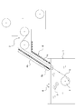
- FIG. 1 is a diagram schematically showing a molten metal plating facility suitable for use in the practice of the present invention.
- reference numeral 1 denotes a bathtub in which molten metal is accommodated
- 2 is a sink roll placed in the bathtub 1 and changes the traveling direction of the steel strip S to be plated
- 3 is above the sink roll 2
- 4 is a wiping nozzle that adjusts the thickness of the plating layer by blowing gas to the steel strip S placed on the bath surface and pulled up from the bathtub 1
- 5 is a snout whose lower end is immersed in the molten metal of the bathtub 1 and whose upper end is connected to the equipment of the annealing furnace.
- the snout 5 has a passage for introducing the steel strip S that has been annealed into the molten metal of the bathtub 1 without touching the atmosphere.
- Numeral 6 is a heating means provided on the outer wall of the snout 5, and numeral 7 is a turn-down roll chamber provided on the exit side of the annealing furnace.
- the heating means 6 is composed of a lower heating means 6a for heating the lower part of the snout 5 and an upper heating means 6b for heating the upper part so that appropriate temperature adjustment can be performed at the lower and upper parts of the snout 5.
- a heater, a heat exchanger, or the like can be applied.
- the heating method is not particularly limited as long as it can efficiently heat the atmospheric temperature in the snout 5.
- the heating means 6, it can also provide in the turndown roll chamber 7 as needed.
- FIG. 2 is an enlarged view showing a cross section of the snout 5 in the vicinity of the bath surface of the bathtub 1.
- the bath temperature is set to about 440 to 480 ° C., and the temperature of the steel strip S subjected to the plating treatment is also set to the same level.
- the wall temperature of the snout 5 is often much lower than the bath surface temperature, especially when the wall surface of the snout is not heated, and generally the temperature close to the bathtub 1 is higher.
- the lower temperature and the upper temperature of the snout 5 are set by the heating means 6 so that the upper temperature of the snout ⁇ the lower temperature of the snout ⁇ the plating bath surface temperature.
- the ambient temperature in the snout is It becomes uniform and the convection of the metal vapor is less likely to occur due to the homogenization of the ambient temperature, and the metal vapor does not precipitate at any location in the snout 5 because the wall surface has a temperature equal to or higher than the melting point of zinc. Therefore, the vapor pressure of the gas in the vicinity of the plating bath surface is maintained at a high level (the formation of aggregates such as ash that causes the surface defects by limiting the evaporation of the molten metal).
- the lower temperature of the snout 5 is preferably set to the plating bath surface temperature + 50 ° C. or lower, because the effect is saturated even if the temperature is higher than this, resulting in energy loss. .
- the upper temperature of the snout 5 needs to be equal to or higher than the lower temperature of the snout, and is preferably set to the plating bath surface temperature +50 to 100 ° C.
- the upper temperature of the snout 5 is the same as that of the snout 5. This is because the temperature range is suitable for limiting the convection of the atmospheric gas by providing a temperature gradient by keeping the temperature equal to or lower than the lower temperature.
- too high temperature is not preferable from the viewpoint of energy loss due to temperature rise. According to the present invention, the rate of occurrence of surface defects due to aggregates can be reduced regardless of the thickness, width, material, etc. of the steel sheet.
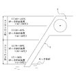
- FIG. 3 is a diagram schematically showing the side surface of the snout 5.
- the upper temperature and lower temperature of the snout 5 are divided into four regions (i) to (d) in the height direction, and the wall portion of the snout is divided into each region. Measure the temperature with a thermocouple, etc., find the average value at the lower part (b), (b) and upper part (c) of the snout 5, respectively. Good.
- (a) is set to a temperature range of the plating bath surface temperature +0 to 50 ° C.
- the temperature range of the plating bath surface +20 to 50 ° C. (c) the temperature range of the plating bath surface +50 to 80 ° C., and (d) the plating bath surface temperature.
- the temperature is preferably in the temperature range of +50 to 100 ° C.
- the intermediate points (back side, front side, 4 points on the OP side and DR side) are preferably measured at equal intervals in the height direction of the snout 5 from the plating bath surface +200 mm, for example, at intervals of 500 mm.
- the plating bath temperature Steel strip with a thickness of 0.4 to 3.3 mm and a width of 800 to 1850 mm under the conditions of 420 to 500 ° C., plating bath Al concentration of 0.1 to 0.3 mass%, and line speed of 20 to 180 mpm (material: SPCC ( JIS G 3141), annealing temperature (heating zone discharge side temperature: 500 to 1000 ° C.), the lower temperature of the snout and the upper temperature of the snout are the conditions shown in Table 1, and the obtained plating The surface quality of the steel strip was investigated.
- the wall temperature of the snout As is apparent from Table 1, by controlling the wall temperature of the snout according to the present invention, that is, the upper temperature of the snout ⁇ the lower temperature of the snout ⁇ the plating bath surface temperature, and the lower temperature of the snout is the plating bath surface temperature + 50 ° C.
- the convection control of metal vapor was performed with the top temperature of the snout set to the plating bath surface temperature +50 to 100 ° C., it was confirmed that the adhesion of condensate (ash) was suppressed and the surface quality was good.
- the steel strips with good surface quality were also investigated for their mechanical properties (yield point, tensile strength, elongation), but it was confirmed that they were within acceptable limits and had no problems. .
Landscapes
- Chemical & Material Sciences (AREA)
- Chemical Kinetics & Catalysis (AREA)
- Engineering & Computer Science (AREA)
- Materials Engineering (AREA)
- Mechanical Engineering (AREA)
- Metallurgy (AREA)
- Organic Chemistry (AREA)
- Coating With Molten Metal (AREA)
Abstract
連続溶融めっきラインのスナウト内における鋼帯への凝縮物の付着を、大掛かりな設備を必要としたり、無駄なエネルギーを消費することなしに回避して溶融めっき鋼帯を製造することができる方法を提案することを目的とし、焼鈍処理を終えた鋼帯をスナウトを通して溶融金属めっき浴へ連続的に導入してめっき処理を施す溶融めっき鋼帯の製造方法に関し、該スナウトの下部温度および該スナウトの上部温度を、スナウトの上部温度≧スナウトの下部温度≧めっき浴面温度とする。
Description
本発明は、連続溶融めっきラインのスナウト内における鋼帯への凝縮物付着を防止した溶融めっき鋼帯の製造方法に関するものである。
鋼帯の連続溶融めっきラインでは、焼鈍炉にて焼鈍処理された鋼帯を筒型形状をなすスナウトを通して溶融めっき浴へ導入している。スナウトは、その先端部(下端部)がめっき浴に浸漬されており、焼鈍を終えた鋼帯を大気雰囲気から遮断する機能を備えているが、かかるスナウトにおいては従来、以下に述べるような不具合を有しておりその解決が望まれていた。
すなわち、スナウトの内部ではめっき浴の金属蒸気が発生しており、その金属蒸気がスナウトの壁面に接触、冷却されることによって凝縮物(アッシュ)が生成される。そして、この凝縮物がスナウトを通る鋼帯の表面に付着すると、該凝縮物が鋼帯に付着したままめっき処理がなされることになり、これがめっき鋼板の表面品質に悪影響を及ぼす原因になっていた。
凝縮物の付着に起因した鋼板の表面品質の改善を図った従来技術として、例えば、特許文献1には、スナウト内の溶融めっき浴から蒸発する金属蒸気を、スナウト壁面に設けられたヒータにより加熱するとともに金属蒸気を含む雰囲気ガスを雰囲気ガス処理回路を通すことによって取り除く技術が開示されている。
また、特許文献2には、ターンダウンロール室およびスナウト内の雰囲気温度および内壁温度を、めっき浴直上から連続炉側のターンダウンロール室の範囲で、めっき浴との温度差を-150℃以内で付与する技術が提案されており、特許文献3には、スナウト内の雰囲気ガスをブロワにて吸引し、吸引された雰囲気ガスをヒューム凝固回収装置で冷却、さらにフィルターを通して雰囲気ガス中の金属微粉を分離したのち、雰囲気ガスを再度雰囲気温度に加熱してスナウト内へ導入する技術が、さらに、特許文献4には、連続溶融亜鉛めっきラインのターンダウンロール室の天井部を加熱手段により加熱昇温する技術が開示されている。
しかしながら、特許文献1においては、大掛かりな設備を別途設ける必要があり、設備コスト、メンテナンスにかかるコストの上昇が避けられない。また、雰囲気ガスの冷却、再加熱を行う必要もあることからエネルギーロスが大きく、場合によってはめっき金属の蒸発を促進させてしまうこともあり、めっき金属の原単位ロス等が大きい。
また、特許文献2においては、ターンダウンロール室およびスナウト内の雰囲気温度および内壁温度をめっき浴直上から連続炉側のターンダウンロール室の範囲で、めっき浴との温度差を-150℃以内で付与することによって金属ヒュームの自然対流を促進させ、これにより金属ヒュームをスナウト取付け部より上流側に強制的に移送させることから、めっき金属の蒸発量の増加によるめっき金属の原単位の悪化が避けられない。また、加熱部以外の場所での金属凝縮を促すため、凝縮物の除去作業が必要となるほか、凝縮物の接触、付着により鋼帯に擦り傷が発生する場合もある。さらに、この方法では、凝縮物の根本原因である金属ヒュームを積極的に対流させていることから、スナウト内壁各部で生じる凝縮物を防止するには至らず、例えば凝縮物がスナウト上面側(鋼板がシンクロールに接する側の面)の内壁から鋼板に付着することによる表面欠陥の問題等が残されている。
また、特許文献3では、特許文献1と同様、大掛かりな設備を別途設ける必要があり、設備コスト、メンテナンスにかかるコストの上昇が避けられないうえ、雰囲気ガスの冷却、再加熱を行う必要もありエネルギーロス、めっき金属の原単位ロスの観点からメリットが小さい。
さらに、特許文献4の技術においては、雰囲気ガスの対流を促進させることによって凝縮物の付着を防止するものであることから特許文献2と同様の不具合があり、しかも、ここに開示された技術は、ターンダウンロール室に限定されるものであって、スナウト内での凝縮物の付着に起因した鋼帯の品質劣化を防止することについては何ら考慮が払われていない。
本発明の課題は、連続溶融めっきラインのスナウト内における鋼帯への凝縮物の付着を、大掛かりな設備を必要としたり、無駄なエネルギーを消費することなしに回避することができ、品質の良好なめっき鋼帯を安定して製造できる、溶融めっき鋼帯の製造方法を提案するところにある。
本発明は、焼鈍処理を終えた鋼帯をスナウトを通して溶融金属めっき浴へ連続的に導入してめっき処理を施す溶融めっき鋼帯の製造方法に関し、該スナウトの下部温度および該スナウトの上部温度を、
スナウトの上部温度≧スナウトの下部温度≧めっき浴面温度
とすることを特徴とする溶融めっき鋼帯の製造方法である。
スナウトの上部温度≧スナウトの下部温度≧めっき浴面温度
とすることを特徴とする溶融めっき鋼帯の製造方法である。
上記の構成からなる方法において、前記スナウトの下部温度を、めっき浴面温度+50℃以下とし、前記スナウトの上部温度を、めっき浴面温度+50~100℃とする、ことが望ましい。
また、前記スナウトの下部温度および該スナウトの上部温度は、該スナウトの周りに設けられた加熱手段を用いて調整するのが好ましい。
めっき浴の直上からターンダウンロール室の上壁面までの垂直距離をスナウトの高さと定義すると、本発明では、その高さの上50%をスナウトの上部、下50%をスナウトの下部ということとする。スナウトの上部温度、スナウトの下部温度は、それぞれその範囲での壁面の平均温度をいうものとする。平均温度の求め方は特に限定されないが、スナウトの高さ方向や周方向のそれぞれ複数点で測温する方法や、あらかじめ、複数点で測温を行って導き出した平均的な温度を示す場所で測温する方法などが考えられる。また、スナウトの内壁面の温度を直接的に測温することが好ましいが、内壁面と外壁面との温度差を予測できるならば、外壁面で測温してもよい。スナウトとして、4辺の壁部から構成された箱型形状を有するスナウトを適用する場合にあっては、スナウトの上部、スナウトの下部のそれぞれで、スナウト外周の各壁部の中間地点の4点を基準とし、そこからスナウトの高さ方向に等間隔で8箇所程度測温(熱電対等による)してその平均値を求め、その平均値をそれぞれスナウトの下部温度、上部温度とするのが望ましい。スナウトの下部の最もめっき浴面に近い測温位置は、浴面+200mm程度とする。
スナウトの下部温度および上部温度を、スナウトの上部温度≧スナウトの下部温度≧めっき浴面温度とすることによりスナウトの壁面には、温度勾配が付与され、スナウト内における雰囲気温度が均一化される。そして、雰囲気温度の均一化により金属蒸気の対流が起こりにくくなり、めっき浴面付近のガスの蒸気圧が高水準に保持される結果、溶融金属の蒸発が制限されて表面欠陥の原因となる凝集物の生成が抑制される。とくに、スナウトの下部温度がめっき浴面温度+50℃以下、スナウトの上部温度がめっき浴面温度+50~100℃とすることにより凝集物の生成抑制効果をより一層高めることができる。
以下、図面を用いて本発明をより具体的に説明する。
図1は、本発明の実施に用いて好適な溶融金属めっき設備を模式的に示した図である。
図1は、本発明の実施に用いて好適な溶融金属めっき設備を模式的に示した図である。
図における符号1は、溶融金属が収容された浴槽、2は、浴槽1内に浸漬配置され、めっき処理すべき鋼帯Sの進行方向を転換するシンクロール、3は、シンクロール2の上方に配置され、鋼帯Sの案内と形状矯正を行うサポートロール、4は、浴面上に配置され浴槽1から引き上げられた鋼帯Sにガスを吹き付けてめっき層の厚さを調整するワイピングノズル、5は、下端部が浴槽1の溶融金属に浸漬され上端部が焼鈍炉の設備につながるスナウトである。スナウト5は、焼鈍処理を終えた鋼帯Sを大気雰囲気に触れさせることなしに浴槽1の溶融金属中へ導入する通路を有している。
また、符号6は、スナウト5の外側壁に設けられた加熱手段、7は、焼鈍炉の出側に設けられたターンダウンロール室である。加熱手段6は、スナウト5の下部、上部において適切な温度調整ができるようにスナウト5の下部を加熱する下部加熱手段6aと、上部を加熱する上部加熱手段6bで構成される。加熱手段6としては、ヒーターや熱交換器等が適用できるが、スナウト5内の雰囲気温度を効率的に加熱できるものであればその加熱方式についてはとくに限定されない。加熱手段6については、必要に応じてターンダウンロール室7にも設けることができる。
図2は、浴槽1の浴面近傍域におけるスナウト5の断面を拡大して示した図である。通常、溶融金属として溶融亜鉛(めっき浴)が用いられる場合、その浴温度は、440~480℃程度に設定され、めっき処理に供される鋼帯Sの温度も同程度に設定されており、スナウト5の壁温度は、特にスナウト壁面を加熱していない場合、浴面温度よりかなり低い温度になっていることが多く、一般的には、浴槽1に近い方が高温になっている。
かかる状況においては、めっき浴から亜鉛が蒸発しスナウト5の通路および焼鈍炉の炉内へと拡散していき、該蒸気がスナウト5の壁面で冷却されることによりアッシュ(ZnO)として析出するとともにそれが堆積する。そして堆積したアッシュはスナウト5の通路を通過する鋼帯Sの表面に落下、付着、巻き込まれることでめっき鋼帯の表面品質が損なわれることになっていたのである。
本発明は、加熱手段6により、スナウト5の下部温度および上部温度を、スナウトの上部温度≧スナウトの下部温度≧めっき浴面温度とするものであり、これによれば、スナウト内における雰囲気温度が均一化され、雰囲気温度の均一化により金属蒸気の対流が起こりにくくなるとともに、スナウト5内のいずれの箇所においても、壁面が亜鉛の融点以上の温度を有することで金属蒸気が析出することがなくなるため、めっき浴面付近のガスの蒸気圧が高水準に保持される(溶融金属の蒸発が制限されて表面欠陥の原因となるアッシュの如き凝集物の生成が抑制される)。
本発明においてスナウト5の下部温度は、めっき浴面温度+50℃以下とするのが好ましいとしたが、その理由は、これ以上高温にしても効果は飽和しており、エネルギーロスとなるためである。
また、スナウト5の上部温度は、スナウトの下部温度以上にする必要があり、めっき浴面温度+50~100℃とするのが好ましいとしたが、その理由は、スナウト5の上部温度をスナウト5の下部温度と同等とするか、それよりも高温に保持することによって温度勾配を付与し、雰囲気ガスの対流を制限するために適切な温度範囲だからである。スナウト5の上部温度についても、過剰に高温にすることは昇温に係るエネルギーロスの観点で好ましくない。本発明によれば、鋼板の板厚、幅、素材などによらず、凝集物起因の表面欠陥発生率を低下させることができる。
図3は、スナウト5の側面を模式的に示した図である。スナウト5の上部温度、下部温度は、例えば、図3に示すように、スナウト5をその高さ方向に(イ)~(ニ)の4つの領域に区分し、各領域毎にスナウトの壁部の温度を熱電対等により測定し、スナウト5の下部(イ)、(ロ)、上部(ハ)(ニ)でそれぞれ平均値を求め、その平均値をスナウト5の下部温度、上部温度とすればよい。とくに、スナウト5をその高さ方向に(イ)~(ニ)の4つの領域に区分した場合、(イ)は、めっき浴面温度+0~50℃の温度範囲とすることが、また、(ロ)は、めっき浴面温度+20~50℃の温度範囲とすることが、(ハ)は、めっき浴面温度+50~80℃の温度範囲とすることが、さらに(ニ)は、めっき浴面温度+50~100℃の温度範囲とすることが好ましい。なお、スナウト5の壁部を測温するにあたっては、該スナウト5が4辺の壁部で構成された箱型形状を有するものの場合には、各辺の壁部の中間地点(裏側、表側、OP側、DR側の4点)を基準としてめっき浴面+200mmからスナウト5の高さ方向にそれぞれ等間隔、例えば、500mm間隔で測定するのがよい。
スナウト通路断面積が0.9m2で、めっき浴直上からターンダウンロール室の出側上壁まで至る長さが8mになるスナウトを備えた連続溶融亜鉛めっき設備を使用して、めっき浴温度:420~500℃、めっき浴Al濃度0.1~0.3mass%、ライン速度:20~180mpmの条件で、板厚0.4~3.3mm、幅800~1850mmの鋼帯(材質:SPCC(JIS G 3141で規定)、焼鈍温度(加熱帯出側温度):500~1000℃)のめっき処理を施す際に、スナウトの下部温度、スナウトの上部温度を表1に示す条件とし、得られためっき鋼帯の表面品質についての調査を行った。その結果を、スナウトの下部温度、上部温度とともに表1に示す。なお、鋼帯の表面品質は、凝集物(アッシュ)起因の表面欠陥発生率で評価した。また、スナウト内の温度調整は、チューブヒータを用いて行った。

表1から明らかなように、本発明にしたがいスナウトの壁面温度を制御することにより、すなわち、スナウトの上部温度≧スナウトの下部温度≧めっき浴面温度、スナウトの下部温度をめっき浴面温度+50℃以下、スナウトの上部温度をめっき浴面温度+50~100℃として金属蒸気の対流制御を行った場合には、凝縮物(アッシュ)の付着が抑制され、表面品質が良好であることが確認された。なお、表面品質の良好な鋼帯については、その機械的特性(降伏点、引張強さ、伸び)についても調査を行ったが、許容範囲に収まっており、何ら問題がないことが確認された。
本発明によれば、大掛かりな設備を必要としたり、無駄なエネルギーを消費することなしに表面品質の良好なめっき鋼帯を安定して製造可能な方法が提供できる。
1 浴槽
2 シンクロール
3 サポートロール
4 ワイピングノズル
5 スナウト
6 加熱手段
7 ターンダウンロール室
S 鋼帯
2 シンクロール
3 サポートロール
4 ワイピングノズル
5 スナウト
6 加熱手段
7 ターンダウンロール室
S 鋼帯
Claims (3)
- 焼鈍処理を終えた鋼帯をスナウトを通して溶融金属めっき浴へ連続的に導入してめっき処理を施す溶融めっき鋼帯の製造方法に関し、
該スナウトの下部温度および該スナウトの上部温度を、
スナウトの上部温度≧スナウトの下部温度≧めっき浴面温度
とすることを特徴とする溶融めっき鋼帯の製造方法。 - 前記スナウトの下部温度を、めっき浴面温度+50℃以下とし、前記スナウトの上部温度を、めっき浴面温度+50~100℃とする、ことを特徴とする請求項1に記載した溶融めっき鋼帯の製造方法。
- 前記スナウトの下部温度および該スナウトの上部温度を、該スナウトの周りに設けられた加熱手段を用いて調整することを特徴とする請求項1または2に記載した溶融めっき鋼帯の製造方法。
Priority Applications (3)
| Application Number | Priority Date | Filing Date | Title |
|---|---|---|---|
| CN201880018458.6A CN110418854B (zh) | 2017-03-31 | 2018-03-26 | 热镀钢带的制造方法 |
| JP2018533855A JP6575785B2 (ja) | 2017-03-31 | 2018-03-26 | 溶融めっき鋼帯の製造方法 |
| MX2019011447A MX2019011447A (es) | 2017-03-31 | 2018-03-26 | Metodo para la fabricacion de banda de acero chapeada por inmersion en caliente. |
Applications Claiming Priority (2)
| Application Number | Priority Date | Filing Date | Title |
|---|---|---|---|
| JP2017070992 | 2017-03-31 | ||
| JP2017-070992 | 2017-03-31 |
Publications (1)
| Publication Number | Publication Date |
|---|---|
| WO2018181091A1 true WO2018181091A1 (ja) | 2018-10-04 |
Family
ID=63677588
Family Applications (1)
| Application Number | Title | Priority Date | Filing Date |
|---|---|---|---|
| PCT/JP2018/011973 Ceased WO2018181091A1 (ja) | 2017-03-31 | 2018-03-26 | 溶融めっき鋼帯の製造方法 |
Country Status (4)
| Country | Link |
|---|---|
| JP (1) | JP6575785B2 (ja) |
| CN (1) | CN110418854B (ja) |
| MX (1) | MX2019011447A (ja) |
| WO (1) | WO2018181091A1 (ja) |
Citations (4)
| Publication number | Priority date | Publication date | Assignee | Title |
|---|---|---|---|---|
| JPH11286762A (ja) * | 1998-04-01 | 1999-10-19 | Nippon Steel Corp | 連続溶融めっき方法及びその装置 |
| JP2002327256A (ja) * | 2001-04-26 | 2002-11-15 | Nkk Corp | 連続溶融金属めっき方法および装置 |
| JP2008231484A (ja) * | 2007-03-19 | 2008-10-02 | Nippon Steel Corp | 連続溶融亜鉛めっき装置。 |
| WO2016170720A1 (ja) * | 2015-04-21 | 2016-10-27 | Jfeスチール株式会社 | 連続溶融金属めっき方法及び連続溶融金属めっき設備 |
Family Cites Families (4)
| Publication number | Priority date | Publication date | Assignee | Title |
|---|---|---|---|---|
| KR101137621B1 (ko) * | 2009-11-30 | 2012-04-20 | 현대하이스코 주식회사 | 드로스 저감장치를 구비하는 용융아연 도금조 |
| CN103556095B (zh) * | 2013-09-26 | 2015-08-05 | 鞍钢蒂森克虏伯汽车钢有限公司 | 一种表面无条状锌灰和亮点缺陷的热镀锌钢板制造方法 |
| JP6361606B2 (ja) * | 2015-04-21 | 2018-07-25 | Jfeスチール株式会社 | 連続溶融金属めっき方法及び連続溶融金属めっき設備 |
| CN107513680A (zh) * | 2017-08-08 | 2017-12-26 | 常州大学 | 控制连续热浸镀锌锌锅炉鼻子内锌灰形成的方法和装置 |
-
2018
- 2018-03-26 MX MX2019011447A patent/MX2019011447A/es unknown
- 2018-03-26 WO PCT/JP2018/011973 patent/WO2018181091A1/ja not_active Ceased
- 2018-03-26 CN CN201880018458.6A patent/CN110418854B/zh active Active
- 2018-03-26 JP JP2018533855A patent/JP6575785B2/ja active Active
Patent Citations (4)
| Publication number | Priority date | Publication date | Assignee | Title |
|---|---|---|---|---|
| JPH11286762A (ja) * | 1998-04-01 | 1999-10-19 | Nippon Steel Corp | 連続溶融めっき方法及びその装置 |
| JP2002327256A (ja) * | 2001-04-26 | 2002-11-15 | Nkk Corp | 連続溶融金属めっき方法および装置 |
| JP2008231484A (ja) * | 2007-03-19 | 2008-10-02 | Nippon Steel Corp | 連続溶融亜鉛めっき装置。 |
| WO2016170720A1 (ja) * | 2015-04-21 | 2016-10-27 | Jfeスチール株式会社 | 連続溶融金属めっき方法及び連続溶融金属めっき設備 |
Also Published As
| Publication number | Publication date |
|---|---|
| JP6575785B2 (ja) | 2019-09-18 |
| CN110418854B (zh) | 2021-07-27 |
| MX2019011447A (es) | 2019-11-01 |
| CN110418854A (zh) | 2019-11-05 |
| JPWO2018181091A1 (ja) | 2019-04-04 |
Similar Documents
| Publication | Publication Date | Title |
|---|---|---|
| TWI537396B (zh) | 還原爐的露點控制方法及還原爐 | |
| TW201619411A (zh) | 連續熔融鍍金屬方法與熔融鍍鋅鋼帶以及連續熔融鍍金屬設備 | |
| JP6131919B2 (ja) | 合金化溶融亜鉛めっき鋼板の製造方法 | |
| JP6439654B2 (ja) | 溶融亜鉛めっき鋼板の製造方法 | |
| JP2019143239A (ja) | アルミニウムストリップ用通過式炉 | |
| JP6575785B2 (ja) | 溶融めっき鋼帯の製造方法 | |
| JP2897668B2 (ja) | 連続溶融めっきのスナウト内フューム付着防止装置 | |
| JP5928412B2 (ja) | 鋼板の竪型冷却装置、およびそれを用いた溶融亜鉛めっき鋼板の製造方法 | |
| JP5167895B2 (ja) | 溶融めっき鋼帯の製造方法 | |
| JP4306471B2 (ja) | 溶融めっき浴への金属帯進入板温度制御方法 | |
| JP2014043633A (ja) | 連続溶融亜鉛めっき方法 | |
| KR20130122312A (ko) | 스나우트 장치 | |
| JP6303581B2 (ja) | ワイピング装置 | |
| JP6128068B2 (ja) | 合金化溶融亜鉛めっき鋼板の製造方法 | |
| JP2018168435A (ja) | 溶融亜鉛めっき鋼板および溶融亜鉛めっき鋼板の製造方法 | |
| JP4904887B2 (ja) | Nbを含有する極低炭素鋼の焼付け硬化性調整方法 | |
| JP4777158B2 (ja) | 溶融亜鉛めっき線およびその冷却装置 | |
| JP7161292B2 (ja) | 連続溶融金属めっき装置及び連続溶融金属めっき方法 | |
| JP5633403B2 (ja) | めっき浴の浴温制御装置及び金属帯のめっき方法 | |
| JP2016169430A (ja) | 溶融亜鉛めっき鋼板の製造方法 | |
| JP6354069B2 (ja) | 溶融金属めっき鋼帯の製造方法および溶融金属めっき鋼帯の製造ライン | |
| JP5067428B2 (ja) | 電気錫めっき鋼板の製造方法 | |
| JPH03277756A (ja) | 溶融亜鉛めっき装置のスナウト内の異物発生抑制方法およびスナウト装置 | |
| JPH073416A (ja) | 連続メッキ設備 | |
| JP2002275606A (ja) | 連続溶融金属めっきにおけるスナウト内鋼帯表面のドロス付着防止方法及び装置 |
Legal Events
| Date | Code | Title | Description |
|---|---|---|---|
| ENP | Entry into the national phase |
Ref document number: 2018533855 Country of ref document: JP Kind code of ref document: A |
|
| 121 | Ep: the epo has been informed by wipo that ep was designated in this application |
Ref document number: 18774178 Country of ref document: EP Kind code of ref document: A1 |
|
| NENP | Non-entry into the national phase |
Ref country code: DE |
|
| 122 | Ep: pct application non-entry in european phase |
Ref document number: 18774178 Country of ref document: EP Kind code of ref document: A1 |