WO2018181063A1 - 燃焼装置及びガスタービン - Google Patents
燃焼装置及びガスタービン Download PDFInfo
- Publication number
- WO2018181063A1 WO2018181063A1 PCT/JP2018/011893 JP2018011893W WO2018181063A1 WO 2018181063 A1 WO2018181063 A1 WO 2018181063A1 JP 2018011893 W JP2018011893 W JP 2018011893W WO 2018181063 A1 WO2018181063 A1 WO 2018181063A1
- Authority
- WO
- WIPO (PCT)
- Prior art keywords
- ammonia
- combustion
- injection hole
- gas
- fuel
- Prior art date
Links
Images


Classifications
-
- F—MECHANICAL ENGINEERING; LIGHTING; HEATING; WEAPONS; BLASTING
- F23—COMBUSTION APPARATUS; COMBUSTION PROCESSES
- F23R—GENERATING COMBUSTION PRODUCTS OF HIGH PRESSURE OR HIGH VELOCITY, e.g. GAS-TURBINE COMBUSTION CHAMBERS
- F23R3/00—Continuous combustion chambers using liquid or gaseous fuel
- F23R3/02—Continuous combustion chambers using liquid or gaseous fuel characterised by the air-flow or gas-flow configuration
- F23R3/16—Continuous combustion chambers using liquid or gaseous fuel characterised by the air-flow or gas-flow configuration with devices inside the flame tube or the combustion chamber to influence the air or gas flow
-
- F—MECHANICAL ENGINEERING; LIGHTING; HEATING; WEAPONS; BLASTING
- F23—COMBUSTION APPARATUS; COMBUSTION PROCESSES
- F23R—GENERATING COMBUSTION PRODUCTS OF HIGH PRESSURE OR HIGH VELOCITY, e.g. GAS-TURBINE COMBUSTION CHAMBERS
- F23R3/00—Continuous combustion chambers using liquid or gaseous fuel
- F23R3/28—Continuous combustion chambers using liquid or gaseous fuel characterised by the fuel supply
- F23R3/36—Supply of different fuels
-
- F—MECHANICAL ENGINEERING; LIGHTING; HEATING; WEAPONS; BLASTING
- F02—COMBUSTION ENGINES; HOT-GAS OR COMBUSTION-PRODUCT ENGINE PLANTS
- F02C—GAS-TURBINE PLANTS; AIR INTAKES FOR JET-PROPULSION PLANTS; CONTROLLING FUEL SUPPLY IN AIR-BREATHING JET-PROPULSION PLANTS
- F02C3/00—Gas-turbine plants characterised by the use of combustion products as the working fluid
- F02C3/20—Gas-turbine plants characterised by the use of combustion products as the working fluid using a special fuel, oxidant, or dilution fluid to generate the combustion products
- F02C3/22—Gas-turbine plants characterised by the use of combustion products as the working fluid using a special fuel, oxidant, or dilution fluid to generate the combustion products the fuel or oxidant being gaseous at standard temperature and pressure
-
- F—MECHANICAL ENGINEERING; LIGHTING; HEATING; WEAPONS; BLASTING
- F02—COMBUSTION ENGINES; HOT-GAS OR COMBUSTION-PRODUCT ENGINE PLANTS
- F02C—GAS-TURBINE PLANTS; AIR INTAKES FOR JET-PROPULSION PLANTS; CONTROLLING FUEL SUPPLY IN AIR-BREATHING JET-PROPULSION PLANTS
- F02C3/00—Gas-turbine plants characterised by the use of combustion products as the working fluid
- F02C3/20—Gas-turbine plants characterised by the use of combustion products as the working fluid using a special fuel, oxidant, or dilution fluid to generate the combustion products
- F02C3/24—Gas-turbine plants characterised by the use of combustion products as the working fluid using a special fuel, oxidant, or dilution fluid to generate the combustion products the fuel or oxidant being liquid at standard temperature and pressure
-
- F—MECHANICAL ENGINEERING; LIGHTING; HEATING; WEAPONS; BLASTING
- F02—COMBUSTION ENGINES; HOT-GAS OR COMBUSTION-PRODUCT ENGINE PLANTS
- F02C—GAS-TURBINE PLANTS; AIR INTAKES FOR JET-PROPULSION PLANTS; CONTROLLING FUEL SUPPLY IN AIR-BREATHING JET-PROPULSION PLANTS
- F02C7/00—Features, components parts, details or accessories, not provided for in, or of interest apart form groups F02C1/00 - F02C6/00; Air intakes for jet-propulsion plants
- F02C7/22—Fuel supply systems
-
- F—MECHANICAL ENGINEERING; LIGHTING; HEATING; WEAPONS; BLASTING
- F23—COMBUSTION APPARATUS; COMBUSTION PROCESSES
- F23R—GENERATING COMBUSTION PRODUCTS OF HIGH PRESSURE OR HIGH VELOCITY, e.g. GAS-TURBINE COMBUSTION CHAMBERS
- F23R3/00—Continuous combustion chambers using liquid or gaseous fuel
- F23R3/002—Wall structures
-
- F—MECHANICAL ENGINEERING; LIGHTING; HEATING; WEAPONS; BLASTING
- F23—COMBUSTION APPARATUS; COMBUSTION PROCESSES
- F23R—GENERATING COMBUSTION PRODUCTS OF HIGH PRESSURE OR HIGH VELOCITY, e.g. GAS-TURBINE COMBUSTION CHAMBERS
- F23R3/00—Continuous combustion chambers using liquid or gaseous fuel
- F23R3/02—Continuous combustion chambers using liquid or gaseous fuel characterised by the air-flow or gas-flow configuration
- F23R3/16—Continuous combustion chambers using liquid or gaseous fuel characterised by the air-flow or gas-flow configuration with devices inside the flame tube or the combustion chamber to influence the air or gas flow
- F23R3/18—Flame stabilising means, e.g. flame holders for after-burners of jet-propulsion plants
- F23R3/20—Flame stabilising means, e.g. flame holders for after-burners of jet-propulsion plants incorporating fuel injection means
-
- F—MECHANICAL ENGINEERING; LIGHTING; HEATING; WEAPONS; BLASTING
- F23—COMBUSTION APPARATUS; COMBUSTION PROCESSES
- F23R—GENERATING COMBUSTION PRODUCTS OF HIGH PRESSURE OR HIGH VELOCITY, e.g. GAS-TURBINE COMBUSTION CHAMBERS
- F23R3/00—Continuous combustion chambers using liquid or gaseous fuel
- F23R3/02—Continuous combustion chambers using liquid or gaseous fuel characterised by the air-flow or gas-flow configuration
- F23R3/16—Continuous combustion chambers using liquid or gaseous fuel characterised by the air-flow or gas-flow configuration with devices inside the flame tube or the combustion chamber to influence the air or gas flow
- F23R3/18—Flame stabilising means, e.g. flame holders for after-burners of jet-propulsion plants
- F23R3/22—Flame stabilising means, e.g. flame holders for after-burners of jet-propulsion plants movable, e.g. to an inoperative position; adjustable, e.g. self-adjusting
-
- F—MECHANICAL ENGINEERING; LIGHTING; HEATING; WEAPONS; BLASTING
- F23—COMBUSTION APPARATUS; COMBUSTION PROCESSES
- F23R—GENERATING COMBUSTION PRODUCTS OF HIGH PRESSURE OR HIGH VELOCITY, e.g. GAS-TURBINE COMBUSTION CHAMBERS
- F23R3/00—Continuous combustion chambers using liquid or gaseous fuel
- F23R3/28—Continuous combustion chambers using liquid or gaseous fuel characterised by the fuel supply
- F23R3/30—Continuous combustion chambers using liquid or gaseous fuel characterised by the fuel supply comprising fuel prevapourising devices
-
- F—MECHANICAL ENGINEERING; LIGHTING; HEATING; WEAPONS; BLASTING
- F23—COMBUSTION APPARATUS; COMBUSTION PROCESSES
- F23R—GENERATING COMBUSTION PRODUCTS OF HIGH PRESSURE OR HIGH VELOCITY, e.g. GAS-TURBINE COMBUSTION CHAMBERS
- F23R3/00—Continuous combustion chambers using liquid or gaseous fuel
- F23R3/28—Continuous combustion chambers using liquid or gaseous fuel characterised by the fuel supply
- F23R3/34—Feeding into different combustion zones
-
- F—MECHANICAL ENGINEERING; LIGHTING; HEATING; WEAPONS; BLASTING
- F23—COMBUSTION APPARATUS; COMBUSTION PROCESSES
- F23R—GENERATING COMBUSTION PRODUCTS OF HIGH PRESSURE OR HIGH VELOCITY, e.g. GAS-TURBINE COMBUSTION CHAMBERS
- F23R3/00—Continuous combustion chambers using liquid or gaseous fuel
- F23R3/40—Continuous combustion chambers using liquid or gaseous fuel characterised by the use of catalytic means
-
- F—MECHANICAL ENGINEERING; LIGHTING; HEATING; WEAPONS; BLASTING
- F05—INDEXING SCHEMES RELATING TO ENGINES OR PUMPS IN VARIOUS SUBCLASSES OF CLASSES F01-F04
- F05D—INDEXING SCHEME FOR ASPECTS RELATING TO NON-POSITIVE-DISPLACEMENT MACHINES OR ENGINES, GAS-TURBINES OR JET-PROPULSION PLANTS
- F05D2240/00—Components
- F05D2240/35—Combustors or associated equipment
-
- F—MECHANICAL ENGINEERING; LIGHTING; HEATING; WEAPONS; BLASTING
- F23—COMBUSTION APPARATUS; COMBUSTION PROCESSES
- F23R—GENERATING COMBUSTION PRODUCTS OF HIGH PRESSURE OR HIGH VELOCITY, e.g. GAS-TURBINE COMBUSTION CHAMBERS
- F23R2900/00—Special features of, or arrangements for continuous combustion chambers; Combustion processes therefor
- F23R2900/00002—Gas turbine combustors adapted for fuels having low heating value [LHV]
Definitions
- the present disclosure relates to a combustion apparatus and a gas turbine.
- This application claims priority based on Japanese Patent Application No. 2017-060445 for which it applied to Japan on March 27, 2017, and uses the content here.
- Patent Document 1 discloses a combustion apparatus and a gas turbine for burning ammonia as fuel.
- the combustion apparatus and the gas turbine obtain combustion exhaust gas that drives the turbine by premixing ammonia (ammonia for fuel) with natural gas and supplying it to the combustor.
- ammonia ammonia for fuel
- a reduction region is formed that reduces nitrogen oxide (NOx) generated in the combustion region downstream of the combustor using reducing ammonia.
- a transition piece Downstream of the combustor, it is called a transition piece (or scroll) and has a deflecting member that connects the combustor and the turbine inlet and deflects the flow direction of the combustion gas.
- the deflecting member has an inlet portion corresponding to the cross-sectional shape of the combustor, an outlet portion corresponding to a part of the inlet shape of the turbine, and the sectional shape of the deflecting member gradually deformed from the inlet portion toward the outlet portion. And a bent portion.
- the combustion gas flows in the deflection member as described above, for example, the combustion gas collides with the bent portion of the deflection member, or the combustion gas flows at high speed in the vicinity of the outlet portion of the deflection member.
- the heat exchange between the deflecting member and the combustion gas is promoted.
- a high temperature portion that becomes high due to the flow or collision of combustion gas and a low temperature portion that is relatively low in temperature are likely to be formed, and damage such as thermal deformation or cracking due to the temperature difference Can happen.
- the present disclosure has been made in view of the above-described circumstances, and an object of the present invention is to suppress damage such as thermal deformation and cracking caused by a temperature difference in a deflection member provided between a combustion chamber and a turbine inlet. It is what.
- a combustion apparatus is a combustion apparatus that burns fuel ammonia and combustion air in a combustion chamber, and is attached to one end of the combustor liner that forms the combustion chamber.
- a burner provided downstream of the combustor liner in the flow direction of the combustion gas, provided between the deflection member for deflecting the flow direction of the combustion gas, and the burner and the outlet of the deflection member; And at least one ammonia injection hole for supplying the fuel ammonia into the combustion chamber.
- the at least one ammonia injection hole may be provided on a side wall of the combustor liner.
- the at least one ammonia injection hole includes a plurality of ammonia injection holes, and the plurality of ammonia injection holes are provided in the combustor liner so as to be asymmetrical about the central axis of the combustion chamber. It may be provided on the side wall.
- a high temperature portion that is higher than the average temperature in the deflection member is specified in advance, and the temperature of the high temperature portion is lowered by the fuel ammonia supplied from the at least one ammonia injection hole.
- the at least one ammonia injection hole may be arranged.
- a high temperature portion that is higher than the average temperature in the deflection member is specified in advance, and the temperature of the high temperature portion is lowered by the fuel ammonia supplied from the at least one ammonia injection hole.
- the supply amount of the ammonia for fuel supplied from the at least one ammonia injection hole may be adjusted.
- a gas turbine according to an aspect of the present disclosure includes the above-described combustion device.
- ammonia for fuel is supplied from the ammonia injection hole into the combustor liner, a combustion field is formed where the ammonia for fuel burns, and ammonia combustion gas having a relatively low temperature is generated.
- the ammonia combustion gas can collide or flow in a part that tends to be high temperature in the deflecting member, and can suppress damage such as thermal deformation and cracking due to a temperature difference in the deflecting member.
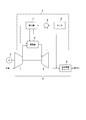
- FIG. 1 is a block diagram illustrating an overall configuration of a combustion apparatus and a gas turbine according to an embodiment of the present disclosure. It is a perspective view showing composition of a combustor in one embodiment of this indication.
- FIG. 3 is a diagram illustrating a configuration of a combustor according to an embodiment of the present disclosure, and is a diagram along line AA in FIG. 2, and is a cross-sectional view illustrating a combustion chamber.
- FIG. 3 is a diagram illustrating a configuration of a combustor according to an embodiment of the present disclosure, and is a diagram along a line BB in FIG. 2, and is a cross-sectional view illustrating a deflection member.
- the gas turbine A includes a compressor 1, a turbine 2, a combustor 3, a reduction catalyst chamber 4, a tank 5, a pump 6, and a vaporizer 7.
- the combustor 3, the tank 5, the pump 6, and the vaporizer 7 constitute the combustion device C in the present embodiment.
- the gas turbine A is a drive source for the generator G, and generates rotational power by burning ammonia as a fuel.
- Compressor 1 generates compressed air by compressing air taken from outside air to a predetermined pressure.
- the compressor 1 supplies compressed air to the combustor mainly as combustion air.
- the combustor 3 generates a flame K in which the natural gas and ammonia supplied to the burner 3c are combusted, and combusts the gaseous ammonia supplied from the vaporizer 7 as fuel. That is, the combustor 3 generates combustion gas by burning natural gas and gaseous ammonia using compressed air as an oxidant, and supplies the combustion gas to the turbine 2.
- the turbine 2 generates rotational power by using the combustion gas as a driving gas.
- the turbine 2 is axially coupled to the compressor 1 and the generator G as shown in the figure, and rotationally drives the compressor 1 and the generator G with its own rotational power.
- the turbine 2 exhausts the combustion gas after power recovery toward the reduction catalyst chamber 4.
- the reduction catalyst chamber 4 is filled with a reduction catalyst, and reduces nitrogen oxide (NOx) contained in the combustion gas to nitrogen (N 2 ) by reduction treatment.
- the tank 5 is a fuel tank that stores a predetermined amount of liquid ammonia, and supplies the liquid ammonia to the pump 6.
- the pump 6 is a fuel pump that pressurizes liquid ammonia supplied from the tank 5 to a predetermined pressure and supplies it to the vaporizer 7.
- the vaporizer 7 can generate gaseous ammonia by vaporizing the liquid ammonia supplied from the pump 6.
- the vaporizer 7 is connected to an ammonia injection hole 3b provided in a side wall 3f of a combustor liner 3a described later, and supplies ammonia to the combustor 3 as gaseous ammonia (ammonia for fuel).
- the vaporizer 7 supplies gaseous ammonia as a reducing agent (reducing ammonia) immediately before the combustor 3 and the reduction catalyst chamber 4.
- the reduction catalyst chamber 4 reduces nitrogen oxides (NOx) in cooperation with the reduction catalyst housed inside and the reducing ammonia.
- the combustor 3 which is one of the characteristic components in the gas turbine A and the combustion apparatus C according to the present embodiment will be described in detail with reference to FIGS. explain.
- the combustor 3 includes a combustor liner 3a, a burner 3c, a rectifier 3d, and a deflection member 3g.
- the burner 3c and the rectifier 3d are attached to one end (first end) of the combustor liner 3a.
- the deflection member 3g is formed at the other end (second end) of the combustor liner 3a.
- the combustor liner 3 a is a cylindrical body, and the internal space of the combustor liner 3 a is a combustion chamber N. 2 is the direction of flow of the combustion gas D in the combustion chamber N.
- the burner 3 c is a fuel injection nozzle that is provided on the central axis of the combustor liner 3 a at one end of the combustor liner 3 a and injects a natural gas flame K into the combustion chamber N.
- the rectifier 3d is provided in an annular shape on the outer periphery of the burner 3c at one end of the combustor liner 3a, and supplies combustion air in a direction from the burner 3c toward the deflecting member 3g.
- An ammonia injection hole 3 b is provided in the side wall 3 f of the combustor liner 3 a, and the ammonia injection hole 3 b is connected to the vaporizer 7.
- the ammonia injection hole 3b can supply gaseous ammonia from the vaporizer 7 into the combustor liner 3a.
- the deflection member 3g is provided on the downstream side of the combustor liner 3a in the flow direction of the combustion gas D.
- One end (inlet part, first end) of the deflection member 3g has a cross-sectional shape corresponding to the combustor liner 3a, and is connected to the combustor liner 3a.
- the other end (outlet portion 3j, second end) of the deflecting member 3g has a cross-sectional shape corresponding to a part of the inlet of the turbine 2, and is connected to the inlet of the turbine 2.
- the deflection member 3g has a bent portion 3h in which the shape of the deflection member 3g is gradually deformed from one end to the other end of the deflection member 3g.
- the deflection member 3g causes the ammonia combustion gas and the combustion gas D to flow in the deflection member 3g, and deflects the flow direction of the ammonia combustion gas and the combustion gas D toward the inlet of the turbine 2. Further, at the outlet 3j of the deflection member 3g, the deflection member 3g causes the ammonia combustion gas and the combustion gas D to flow at a high speed.
- the arrangement of the ammonia injection holes 3b is adjusted so that the temperature of the high temperature portion is lowered by the fuel ammonia supplied from the ammonia injection holes 3b.
- the supply amount of the ammonia for fuel supplied from the ammonia injection hole 3b is adjusted so that the temperature of the high temperature portion is lowered by the ammonia for fuel supplied from the ammonia injection hole 3b.
- the arrangement of the ammonia injection holes 3b or the supply amount of the fuel ammonia supplied from the ammonia injection holes 3b is adjusted so that the fuel ammonia collides with the high temperature part or flows along the high temperature part. It is preferable.
- the ammonia for fuel that lowers the temperature of the high temperature part may be a combustion gas of ammonia for fuel or unburned fuel ammonia.
- liquid ammonia is supplied from the tank 5 to the vaporizer 7 by operating the pump 6, and gaseous ammonia is generated by vaporizing the liquid ammonia in the vaporizer 7.
- gaseous ammonia a part of the gaseous ammonia is supplied as fuel ammonia into the combustor liner 3a, and the remaining gaseous ammonia is supplied as reducing ammonia immediately before the reduction catalyst chamber 4.
- the burner 3c injects natural gas and ammonia into the combustion air swirled by the rectifier 3d to form a flame K.
- the combustion gas D of the flame K flows in the combustion chamber N. At this time, a swirling flow of the combustion gas D is generated around the central axis of the combustor liner 3a.
- gaseous ammonia is injected from the ammonia injection hole 3b toward the inner wall surface facing the ammonia injection hole 3b.
- gaseous ammonia burns with the residual oxygen in the combustion gas D
- an ammonia combustion field 3i is formed in the combustion chamber N, and ammonia combustion gas is generated.
- the ammonia combustion field 3i is formed so as to push away the high-temperature combustion gas D.
- Ammonia has the property of lower calories than hydrocarbon fuel. For this reason, the ammonia combustion gas generated from the ammonia combustion field 3 i is at a relatively lower temperature than the combustion gas D. Since the combustion temperature of ammonia is low, in the cross section of the combustor 3 after injecting gaseous ammonia from the ammonia injection hole 3b, the high temperature part of the combustion gas D (hydrocarbon combustion gas) pushed away by gaseous ammonia and ammonia combustion This results in an uneven temperature distribution in which there is a low temperature portion of the gas.
- the position of the ammonia combustion field 3i changes according to the swirling flow.
- the ammonia combustion field 3i also turns as it goes downstream.
- gaseous ammonia is injected toward the combustion chamber N from the ammonia injection hole 3b, the gaseous ammonia burns while pushing away a relatively uniform flow of the combustion gas D formed by the burner 3c.
- the high-temperature combustion gas D and the low-temperature ammonia combustion gas flow as a swirl flow from the ammonia combustion field 3i toward the deflecting member 3g.
- a low temperature region L in which ammonia combustion gas flows and a high temperature region H in which high temperature combustion gas D flows are generated.
- a low temperature region L is formed in a portion that tends to become high temperature due to collision of combustion gas.
- a low temperature region L is formed at the outlet 3j of the deflecting member 3g in a portion that tends to become high temperature due to the high-speed flow of the combustion gas.
- a low-temperature ammonia combustion gas flows to a portion that is likely to become high temperature in a conventional member provided between the combustion chamber and the turbine inlet, for example, to a portion that tends to become high temperature in the deflection member 3g. Since the low temperature region L to be formed is formed, damage such as thermal deformation and cracking in the deflecting member 3g due to the temperature difference between the high temperature portion and the low temperature portion can be suppressed.
- the above embodiment relates to a case where the present disclosure is applied to the combustion device C of the gas turbine A, but the present disclosure is not limited to this.
- the combustion apparatus according to the present disclosure is applicable to various apparatuses other than the gas turbine A, for example, a boiler and an incineration facility.
- the number of ammonia injection holes 3b provided in the side wall 3f is one, but the number of ammonia injection holes 3b may be plural.
- the plurality of ammonia injection holes 3b are preferably provided on the side wall 3f of the combustor liner 3a so as to be asymmetrical around the central axis of the combustor liner 3a.
- ammonia combustion gas having a relatively low temperature can collide with a portion of the conventional deflecting member that is likely to become high temperature. Or ammonia combustion gas can be made to flow along the part which becomes high temperature easily. Damage such as thermal deformation and cracking due to the temperature difference in the deflection member 3g can be suppressed.
- ammonia reducing ammonia
- the present disclosure is not limited to this.
- a reducing agent other than ammonia may be used.
- the fuel supplied by the burner 3c into the combustion chamber N is natural gas and ammonia.
- the present disclosure is not limited to a combination of a fuel having a high flame temperature and a fuel having a low flame temperature.
- the ammonia combustion field 3i may be a supply region to which unburned ammonia gas is supplied. In this case, unburned ammonia gas is denitrated together with NOx in the denitration device, and therefore does not leak from the gas turbine A.
- the deflecting member provided between the combustion chamber and the turbine inlet, it is possible to suppress damage such as thermal deformation and cracking due to a temperature difference.
- a Gas turbine C Combustion device D Combustion gas H High temperature region K Natural gas flame L Low temperature region N Combustion chamber 1 Compressor 2 Turbine 3 Combustor 3a Combustor liner 3b Ammonia injection hole 3c Burner 3d Rectifier 3e Ammonia gas 3f Side wall 3g Deflection member 3h Bent part 3i Ammonia combustion field 3j Outlet part 4 Reduction catalyst chamber 5 Tank 6 Pump 7 Vaporizer
Landscapes
- Engineering & Computer Science (AREA)
- Chemical & Material Sciences (AREA)
- Combustion & Propulsion (AREA)
- Mechanical Engineering (AREA)
- General Engineering & Computer Science (AREA)
- Chemical Kinetics & Catalysis (AREA)
Abstract
Description
本願は、2017年3月27日に日本に出願された特願2017-060445号に基づき優先権を主張し、その内容をここに援用する。
本実施形態に係るガスタービンAは、図1に示すように圧縮機1、タービン2、燃焼器3、還元触媒チャンバ4、タンク5、ポンプ6、及び気化器7を備えている。また、これらの構成要素のうち、燃焼器3、タンク5、ポンプ6、及び気化器7は、本実施形態における燃焼装置Cを構成している。ガスタービンAは、発電機Gの駆動源であり、燃料であるアンモニアを燃焼することにより回転動力を発生させる。
タービン2は、図示するように圧縮機1及び発電機Gと軸結合しており、自らの回転動力によって圧縮機1及び発電機Gを回転駆動する。タービン2は、動力回収した後の燃焼ガスを還元触媒チャンバ4に向けて排気する。還元触媒チャンバ4は、内部に還元触媒が充填されており、燃焼ガスに含まれる窒素酸化物(NOx)を還元処理することにより窒素(N2)に還元する。
バーナ3c及び整流器3dは、燃焼器ライナ3aの一端(第1端)に取り付けられている。偏向部材3gは、燃焼器ライナ3aの他端(第2端)に形成されている。燃焼器ライナ3aは、筒状体であり、燃焼器ライナ3aの内部空間は、燃焼室Nである。なお、図2における矢印の方向は、燃焼室N内における燃焼ガスDの流動方向である。
(2)上記実施形態では、側壁3fに設けられたアンモニア噴射孔3bの個数は1つであるが、アンモニア噴射孔3bの個数は複数であってもよい。この場合、複数のアンモニア噴射孔3bは、燃焼器ライナ3aの中心軸周りに非対称となるように燃焼器ライナ3aの側壁3fに設けられていることが好ましい。このように複数のアンモニア噴射孔3bを配置することで、アンモニア噴射孔3bから噴射した気体アンモニアは、燃焼器3の断面において不均一な燃焼場を形成する。これにより、従来の偏向部材において高温となり易い部分に、比較的温度が低いアンモニア燃焼ガスを衝突させることができる。あるいは、高温となり易い部分に沿うように、アンモニア燃焼ガスを流動させることができる。偏向部材3gにおける温度差に起因する熱変形や割れ等の破損を抑制することができる。
(3)上記実施形態では、還元剤としてアンモニア(還元用アンモニア)を用いたが、本開示はこれに限定されない。アンモニア(還元用アンモニア)以外の還元剤を用いてもよい。
(4)上記実施形態では、バーナ3cが燃焼室N内に供給する燃料は、天然ガスとアンモニアであったが、本開示は、火炎温度の高い燃料と低い燃料の組み合わせであれば、燃料を限定しない。
(5)アンモニア燃焼場3iは、未燃のアンモニアガスが供給された供給領域であってもよい。この場合、未燃のアンモニアガスは、脱硝装置でNOxとともに脱硝処理されるため、ガスタービンAから漏洩することはない。
C 燃焼装置
D 燃焼ガス
H 高温領域
K 天然ガス火炎
L 低温領域
N 燃焼室
1 圧縮機
2 タービン
3 燃焼器
3a 燃焼器ライナ
3b アンモニア噴射孔
3c バーナ
3d 整流器
3e アンモニアガス
3f 側壁
3g 偏向部材
3h 屈曲部
3i アンモニア燃焼場
3j 出口部
4 還元触媒チャンバ
5 タンク
6 ポンプ
7 気化器
Claims (6)
- 燃料用アンモニアと燃焼用空気を燃焼室内で燃焼させる燃焼装置であって、
前記燃焼室を形成する燃焼器ライナと、
前記燃焼器ライナの一端に取り付けられたバーナと、
燃焼ガスの流動方向において前記燃焼器ライナよりも下流側に設けられ、前記燃焼ガスの前記流動方向を偏向する偏向部材と、
前記バーナと前記偏向部材の出口との間に設けられ、前記燃料用アンモニアを前記燃焼室の内部に供給する少なくとも一つのアンモニア噴射孔と、
を備える、燃焼装置。 - 前記少なくとも一つのアンモニア噴射孔が前記燃焼器ライナの側壁に設けられている、請求項1に記載の燃焼装置。
- 前記少なくとも一つのアンモニア噴射孔は複数のアンモニア噴射孔を備え、
前記複数のアンモニア噴射孔は、前記燃焼室の中心軸周りに非対称となるように前記燃焼器ライナの側壁に設けられている、請求項1に記載の燃焼装置。 - 前記偏向部材において平均温度よりも高温となる高温部を予め特定し、前記少なくとも一つのアンモニア噴射孔から供給される前記燃料用アンモニアによって前記高温部の温度が低くなるように、前記少なくとも一つのアンモニア噴射孔が配置されている、請求項1から請求項3のいずれか一項に記載の燃焼装置。
- 前記偏向部材において平均温度よりも高温となる高温部を予め特定し、前記少なくとも一つのアンモニア噴射孔から供給される前記燃料用アンモニアによって前記高温部の温度が低くなるように、前記少なくとも一つのアンモニア噴射孔から供給される前記燃料用アンモニアの供給量が調整されている、請求項1から請求項4のいずれか一項に記載の燃焼装置。
- 請求項1から請求項5のいずれか一項に記載の燃焼装置を備える、ガスタービン。
Priority Applications (5)
| Application Number | Priority Date | Filing Date | Title |
|---|---|---|---|
| CN201880009866.5A CN110268196B (zh) | 2017-03-27 | 2018-03-23 | 燃烧装置及燃气轮机 |
| EP18778133.1A EP3604928B1 (en) | 2017-03-27 | 2018-03-23 | Combustion device and gas turbine |
| AU2018242879A AU2018242879B2 (en) | 2017-03-27 | 2018-03-23 | Combustion device and gas turbine |
| KR1020197014998A KR20190077017A (ko) | 2017-03-27 | 2018-03-23 | 연소 장치 및 가스 터빈 |
| US16/534,737 US11231176B2 (en) | 2017-03-27 | 2019-08-07 | Combustion device and gas turbine |
Applications Claiming Priority (2)
| Application Number | Priority Date | Filing Date | Title |
|---|---|---|---|
| JP2017060445A JP6769370B2 (ja) | 2017-03-27 | 2017-03-27 | 燃焼装置及びガスタービン |
| JP2017-060445 | 2017-03-27 |
Related Child Applications (1)
| Application Number | Title | Priority Date | Filing Date |
|---|---|---|---|
| US16/534,737 Continuation US11231176B2 (en) | 2017-03-27 | 2019-08-07 | Combustion device and gas turbine |
Publications (1)
| Publication Number | Publication Date |
|---|---|
| WO2018181063A1 true WO2018181063A1 (ja) | 2018-10-04 |
Family
ID=63676026
Family Applications (1)
| Application Number | Title | Priority Date | Filing Date |
|---|---|---|---|
| PCT/JP2018/011893 WO2018181063A1 (ja) | 2017-03-27 | 2018-03-23 | 燃焼装置及びガスタービン |
Country Status (7)
| Country | Link |
|---|---|
| US (1) | US11231176B2 (ja) |
| EP (1) | EP3604928B1 (ja) |
| JP (1) | JP6769370B2 (ja) |
| KR (1) | KR20190077017A (ja) |
| CN (1) | CN110268196B (ja) |
| AU (1) | AU2018242879B2 (ja) |
| WO (1) | WO2018181063A1 (ja) |
Families Citing this family (7)
| Publication number | Priority date | Publication date | Assignee | Title |
|---|---|---|---|---|
| JP7081407B2 (ja) | 2018-09-11 | 2022-06-07 | 株式会社Ihi | ボイラ |
| JP7183868B2 (ja) * | 2019-02-28 | 2022-12-06 | 株式会社Ihi | 燃焼器バーナ及び燃焼器 |
| JP7167772B2 (ja) * | 2019-02-28 | 2022-11-09 | 株式会社Ihi | 燃焼器 |
| US20220275759A1 (en) * | 2019-08-26 | 2022-09-01 | 8 Rivers Capital, Llc | Flame control in an oxyfuel combustion process |
| EP4361094A1 (en) | 2022-10-24 | 2024-05-01 | Linde GmbH | Method and apparatus for processing ammonia |
| EP4361095A1 (en) | 2022-10-24 | 2024-05-01 | Linde GmbH | Method and apparatus for providing heat |
| EP4361096A1 (en) | 2022-10-24 | 2024-05-01 | Linde GmbH | Method and apparatus for processing ammonia |
Citations (8)
| Publication number | Priority date | Publication date | Assignee | Title |
|---|---|---|---|---|
| JPS5959671U (ja) * | 1982-10-13 | 1984-04-18 | 三菱重工業株式会社 | ガスタ−ビン燃焼器 |
| JPS6143675U (ja) * | 1984-08-21 | 1986-03-22 | 三菱重工業株式会社 | ガスタ−ビンの燃焼器尾筒 |
| JP2005265403A (ja) * | 2004-03-17 | 2005-09-29 | General Electric Co <Ge> | 希釈孔を有するタービン燃焼器移行部品 |
| WO2010082359A1 (ja) * | 2009-01-14 | 2010-07-22 | トヨタ自動車株式会社 | エンジン |
| JP2010539437A (ja) * | 2007-09-14 | 2010-12-16 | シーメンス エナジー インコーポレイテッド | 二次燃料噴射を制御する装置および方法 |
| JP2013139784A (ja) * | 2012-01-04 | 2013-07-18 | General Electric Co <Ge> | ガスタービンエンジンを運転する方法および装置 |
| JP2016191507A (ja) | 2015-03-31 | 2016-11-10 | 株式会社Ihi | 燃焼装置、ガスタービン及び発電装置 |
| JP2017060445A (ja) | 2015-09-25 | 2017-03-30 | 株式会社オーディオテクニカ | 食品成形用圧延ローラ、食品成形装置 |
Family Cites Families (14)
| Publication number | Priority date | Publication date | Assignee | Title |
|---|---|---|---|---|
| US2987873A (en) * | 1955-05-13 | 1961-06-13 | Phillips Petroleum Co | Method and apparatus for using ammonia to increase the air specific impulse of a two-stage compressor turbojet engine |
| EP0101670B1 (de) | 1982-08-23 | 1988-03-09 | Ciba-Geigy Ag | Verfahren zur Herstellung von herbiziden und pflanzenwuchsregulierenden Sulfonylharnstoffen |
| US4522967A (en) | 1984-06-08 | 1985-06-11 | Kimberly-Clark Corporation | Heat sealable water dispersible adhesive |
| JPH02308926A (ja) * | 1989-05-24 | 1990-12-21 | Hitachi Ltd | ガスタービン燃焼器尾筒の冷却構造 |
| US5199255A (en) * | 1991-04-03 | 1993-04-06 | Nalco Fuel Tech | Selective gas-phase nox reduction in gas turbines |
| DE19510744A1 (de) | 1995-03-24 | 1996-09-26 | Abb Management Ag | Brennkammer mit Zweistufenverbrennung |
| EP0908671B1 (de) * | 1997-10-08 | 2003-05-14 | ALSTOM (Switzerland) Ltd | Verfahren zur Verbrennung von gasförmigen, flüssigen sowie mittel-oder niederkalorischen Brennstoffen in einem Brenner |
| JP2004036983A (ja) * | 2002-07-02 | 2004-02-05 | Mitsubishi Heavy Ind Ltd | アンモニア含有ガス処理方法及びその装置 |
| DE202004017725U1 (de) * | 2004-11-15 | 2005-02-03 | Franke, Berndt, Prof. Dr.-Ing. habil. | Anlage und Einrichtung der Kraft-Wärme-Kopplung mit Biomassegas |
| US8375726B2 (en) * | 2008-09-24 | 2013-02-19 | Siemens Energy, Inc. | Combustor assembly in a gas turbine engine |
| US8112216B2 (en) * | 2009-01-07 | 2012-02-07 | General Electric Company | Late lean injection with adjustable air splits |
| US8695351B2 (en) * | 2011-05-05 | 2014-04-15 | General Electric Company | Hula seal with preferential cooling having spring fingers and/or adjacent slots with different widths |
| US20130318991A1 (en) * | 2012-05-31 | 2013-12-05 | General Electric Company | Combustor With Multiple Combustion Zones With Injector Placement for Component Durability |
| JP6255923B2 (ja) * | 2013-11-11 | 2018-01-10 | 株式会社Ihi | 燃焼装置、ガスタービン及び発電装置 |
-
2017
- 2017-03-27 JP JP2017060445A patent/JP6769370B2/ja active Active
-
2018
- 2018-03-23 CN CN201880009866.5A patent/CN110268196B/zh active Active
- 2018-03-23 WO PCT/JP2018/011893 patent/WO2018181063A1/ja unknown
- 2018-03-23 AU AU2018242879A patent/AU2018242879B2/en active Active
- 2018-03-23 KR KR1020197014998A patent/KR20190077017A/ko active IP Right Grant
- 2018-03-23 EP EP18778133.1A patent/EP3604928B1/en active Active
-
2019
- 2019-08-07 US US16/534,737 patent/US11231176B2/en active Active
Patent Citations (8)
| Publication number | Priority date | Publication date | Assignee | Title |
|---|---|---|---|---|
| JPS5959671U (ja) * | 1982-10-13 | 1984-04-18 | 三菱重工業株式会社 | ガスタ−ビン燃焼器 |
| JPS6143675U (ja) * | 1984-08-21 | 1986-03-22 | 三菱重工業株式会社 | ガスタ−ビンの燃焼器尾筒 |
| JP2005265403A (ja) * | 2004-03-17 | 2005-09-29 | General Electric Co <Ge> | 希釈孔を有するタービン燃焼器移行部品 |
| JP2010539437A (ja) * | 2007-09-14 | 2010-12-16 | シーメンス エナジー インコーポレイテッド | 二次燃料噴射を制御する装置および方法 |
| WO2010082359A1 (ja) * | 2009-01-14 | 2010-07-22 | トヨタ自動車株式会社 | エンジン |
| JP2013139784A (ja) * | 2012-01-04 | 2013-07-18 | General Electric Co <Ge> | ガスタービンエンジンを運転する方法および装置 |
| JP2016191507A (ja) | 2015-03-31 | 2016-11-10 | 株式会社Ihi | 燃焼装置、ガスタービン及び発電装置 |
| JP2017060445A (ja) | 2015-09-25 | 2017-03-30 | 株式会社オーディオテクニカ | 食品成形用圧延ローラ、食品成形装置 |
Non-Patent Citations (1)
| Title |
|---|
| See also references of EP3604928A4 |
Also Published As
| Publication number | Publication date |
|---|---|
| EP3604928B1 (en) | 2023-03-15 |
| EP3604928A4 (en) | 2020-12-02 |
| AU2018242879B2 (en) | 2020-10-15 |
| KR20190077017A (ko) | 2019-07-02 |
| US20200003420A1 (en) | 2020-01-02 |
| JP2018162724A (ja) | 2018-10-18 |
| US11231176B2 (en) | 2022-01-25 |
| JP6769370B2 (ja) | 2020-10-14 |
| AU2018242879A1 (en) | 2019-08-22 |
| CN110268196B (zh) | 2020-11-27 |
| CN110268196A (zh) | 2019-09-20 |
| EP3604928A1 (en) | 2020-02-05 |
Similar Documents
| Publication | Publication Date | Title |
|---|---|---|
| WO2018181063A1 (ja) | 燃焼装置及びガスタービン | |
| EP2647911B1 (en) | Combustor | |
| JP6134544B2 (ja) | 作動流体を燃焼器に供給するシステム | |
| JP5606776B2 (ja) | 燃焼システムにおいて燃料ノズルを熱的に保護するための方法及びシステム | |
| JP5860620B2 (ja) | ターボ機械用噴射ノズル | |
| EP2657611B1 (en) | System for supplying fuel to a combustor | |
| JP5599584B2 (ja) | ターボ機械燃焼器用センターボディキャップ及び方法 | |
| CN110506152B (zh) | 燃烧装置以及燃气轮机 | |
| JP2005226847A (ja) | 燃焼装置及び燃焼方法 | |
| JP2012017971A5 (ja) | ||
| JP6327826B2 (ja) | ガスタービンの燃料噴射装置 | |
| JP6154988B2 (ja) | 燃焼器 | |
| US20140007582A1 (en) | Gas Turbine Combustor and Operating Method for Gas Turbine Combustor | |
| WO2019188409A1 (ja) | 燃焼装置及びガスタービン | |
| JP5610446B2 (ja) | ガスタービン燃焼器 | |
| KR102021129B1 (ko) | 연료 노즐, 이를 포함하는 연소기 및 가스 터빈 | |
| EP2626632A2 (en) | Fuel injection assembly for use in turbine engines and method of assembling same | |
| JP7167772B2 (ja) | 燃焼器 | |
| JP2024508474A (ja) | ガスタービンシステムの燃焼安定性を向上させるための水素注入 | |
| KR20190133129A (ko) | 연소기 및 이를 포함하는 가스 터빈 |
Legal Events
| Date | Code | Title | Description |
|---|---|---|---|
| 121 | Ep: the epo has been informed by wipo that ep was designated in this application |
Ref document number: 18778133 Country of ref document: EP Kind code of ref document: A1 |
|
| ENP | Entry into the national phase |
Ref document number: 20197014998 Country of ref document: KR Kind code of ref document: A |
|
| ENP | Entry into the national phase |
Ref document number: 2018242879 Country of ref document: AU Date of ref document: 20180323 Kind code of ref document: A |
|
| NENP | Non-entry into the national phase |
Ref country code: DE |
|
| ENP | Entry into the national phase |
Ref document number: 2018778133 Country of ref document: EP Effective date: 20191028 |