EP2647911B1 - Combustor - Google Patents
Combustor Download PDFInfo
- Publication number
- EP2647911B1 EP2647911B1 EP13161337.4A EP13161337A EP2647911B1 EP 2647911 B1 EP2647911 B1 EP 2647911B1 EP 13161337 A EP13161337 A EP 13161337A EP 2647911 B1 EP2647911 B1 EP 2647911B1
- Authority
- EP
- European Patent Office
- Prior art keywords
- fuel
- fluid
- combustion chamber
- passage
- fuel nozzle
- Prior art date
- Legal status (The legal status is an assumption and is not a legal conclusion. Google has not performed a legal analysis and makes no representation as to the accuracy of the status listed.)
- Active
Links
- 239000000446 fuel Substances 0.000 claims description 115
- 239000012530 fluid Substances 0.000 claims description 96
- 238000002485 combustion reaction Methods 0.000 claims description 57
- 239000000567 combustion gas Substances 0.000 claims description 29
- 238000006243 chemical reaction Methods 0.000 claims description 25
- 239000000203 mixture Substances 0.000 claims description 20
- 239000007788 liquid Substances 0.000 claims description 13
- 238000004891 communication Methods 0.000 claims description 12
- 238000010517 secondary reaction Methods 0.000 claims description 9
- 239000003570 air Substances 0.000 description 19
- MWUXSHHQAYIFBG-UHFFFAOYSA-N nitrogen oxide Inorganic materials O=[N] MWUXSHHQAYIFBG-UHFFFAOYSA-N 0.000 description 9
- 239000007789 gas Substances 0.000 description 8
- 238000000034 method Methods 0.000 description 7
- 230000007704 transition Effects 0.000 description 6
- 238000001816 cooling Methods 0.000 description 3
- 238000013461 design Methods 0.000 description 3
- 238000004519 manufacturing process Methods 0.000 description 3
- 238000011144 upstream manufacturing Methods 0.000 description 3
- ATUOYWHBWRKTHZ-UHFFFAOYSA-N Propane Chemical compound CCC ATUOYWHBWRKTHZ-UHFFFAOYSA-N 0.000 description 2
- 239000012080 ambient air Substances 0.000 description 2
- 239000003085 diluting agent Substances 0.000 description 2
- 230000005611 electricity Effects 0.000 description 2
- 239000003949 liquefied natural gas Substances 0.000 description 2
- VNWKTOKETHGBQD-UHFFFAOYSA-N methane Chemical compound C VNWKTOKETHGBQD-UHFFFAOYSA-N 0.000 description 2
- 238000012986 modification Methods 0.000 description 2
- 230000004048 modification Effects 0.000 description 2
- 230000037361 pathway Effects 0.000 description 2
- IJGRMHOSHXDMSA-UHFFFAOYSA-N Atomic nitrogen Chemical compound N#N IJGRMHOSHXDMSA-UHFFFAOYSA-N 0.000 description 1
- UGFAIRIUMAVXCW-UHFFFAOYSA-N Carbon monoxide Chemical compound [O+]#[C-] UGFAIRIUMAVXCW-UHFFFAOYSA-N 0.000 description 1
- 239000011324 bead Substances 0.000 description 1
- 230000015572 biosynthetic process Effects 0.000 description 1
- 229910002091 carbon monoxide Inorganic materials 0.000 description 1
- 239000000571 coke Substances 0.000 description 1
- 238000004939 coking Methods 0.000 description 1
- 229930195733 hydrocarbon Natural products 0.000 description 1
- 150000002430 hydrocarbons Chemical class 0.000 description 1
- 239000001257 hydrogen Substances 0.000 description 1
- 229910052739 hydrogen Inorganic materials 0.000 description 1
- 125000004435 hydrogen atom Chemical class [H]* 0.000 description 1
- 238000002347 injection Methods 0.000 description 1
- 239000007924 injection Substances 0.000 description 1
- 239000003345 natural gas Substances 0.000 description 1
- 230000002093 peripheral effect Effects 0.000 description 1
- 238000010248 power generation Methods 0.000 description 1
- 230000008569 process Effects 0.000 description 1
- 239000001294 propane Substances 0.000 description 1
- 238000010791 quenching Methods 0.000 description 1
- 238000012552 review Methods 0.000 description 1
- 230000009528 severe injury Effects 0.000 description 1
Images


Classifications
-
- F—MECHANICAL ENGINEERING; LIGHTING; HEATING; WEAPONS; BLASTING
- F23—COMBUSTION APPARATUS; COMBUSTION PROCESSES
- F23R—GENERATING COMBUSTION PRODUCTS OF HIGH PRESSURE OR HIGH VELOCITY, e.g. GAS-TURBINE COMBUSTION CHAMBERS
- F23R3/00—Continuous combustion chambers using liquid or gaseous fuel
- F23R3/28—Continuous combustion chambers using liquid or gaseous fuel characterised by the fuel supply
- F23R3/34—Feeding into different combustion zones
- F23R3/346—Feeding into different combustion zones for staged combustion
-
- F—MECHANICAL ENGINEERING; LIGHTING; HEATING; WEAPONS; BLASTING
- F23—COMBUSTION APPARATUS; COMBUSTION PROCESSES
- F23C—METHODS OR APPARATUS FOR COMBUSTION USING FLUID FUEL OR SOLID FUEL SUSPENDED IN A CARRIER GAS OR AIR
- F23C6/00—Combustion apparatus characterised by the combination of two or more combustion chambers or combustion zones, e.g. for staged combustion
- F23C6/04—Combustion apparatus characterised by the combination of two or more combustion chambers or combustion zones, e.g. for staged combustion in series connection
- F23C6/045—Combustion apparatus characterised by the combination of two or more combustion chambers or combustion zones, e.g. for staged combustion in series connection with staged combustion in a single enclosure
- F23C6/047—Combustion apparatus characterised by the combination of two or more combustion chambers or combustion zones, e.g. for staged combustion in series connection with staged combustion in a single enclosure with fuel supply in stages
-
- F—MECHANICAL ENGINEERING; LIGHTING; HEATING; WEAPONS; BLASTING
- F23—COMBUSTION APPARATUS; COMBUSTION PROCESSES
- F23C—METHODS OR APPARATUS FOR COMBUSTION USING FLUID FUEL OR SOLID FUEL SUSPENDED IN A CARRIER GAS OR AIR
- F23C2201/00—Staged combustion
- F23C2201/30—Staged fuel supply
-
- F—MECHANICAL ENGINEERING; LIGHTING; HEATING; WEAPONS; BLASTING
- F23—COMBUSTION APPARATUS; COMBUSTION PROCESSES
- F23R—GENERATING COMBUSTION PRODUCTS OF HIGH PRESSURE OR HIGH VELOCITY, e.g. GAS-TURBINE COMBUSTION CHAMBERS
- F23R2900/00—Special features of, or arrangements for continuous combustion chambers; Combustion processes therefor
- F23R2900/03341—Sequential combustion chambers or burners
-
- F—MECHANICAL ENGINEERING; LIGHTING; HEATING; WEAPONS; BLASTING
- F23—COMBUSTION APPARATUS; COMBUSTION PROCESSES
- F23R—GENERATING COMBUSTION PRODUCTS OF HIGH PRESSURE OR HIGH VELOCITY, e.g. GAS-TURBINE COMBUSTION CHAMBERS
- F23R3/00—Continuous combustion chambers using liquid or gaseous fuel
- F23R3/02—Continuous combustion chambers using liquid or gaseous fuel characterised by the air-flow or gas-flow configuration
- F23R3/04—Air inlet arrangements
- F23R3/10—Air inlet arrangements for primary air
- F23R3/12—Air inlet arrangements for primary air inducing a vortex
- F23R3/14—Air inlet arrangements for primary air inducing a vortex by using swirl vanes
-
- F—MECHANICAL ENGINEERING; LIGHTING; HEATING; WEAPONS; BLASTING
- F23—COMBUSTION APPARATUS; COMBUSTION PROCESSES
- F23R—GENERATING COMBUSTION PRODUCTS OF HIGH PRESSURE OR HIGH VELOCITY, e.g. GAS-TURBINE COMBUSTION CHAMBERS
- F23R3/00—Continuous combustion chambers using liquid or gaseous fuel
- F23R3/28—Continuous combustion chambers using liquid or gaseous fuel characterised by the fuel supply
- F23R3/283—Attaching or cooling of fuel injecting means including supports for fuel injectors, stems, or lances
-
- F—MECHANICAL ENGINEERING; LIGHTING; HEATING; WEAPONS; BLASTING
- F23—COMBUSTION APPARATUS; COMBUSTION PROCESSES
- F23R—GENERATING COMBUSTION PRODUCTS OF HIGH PRESSURE OR HIGH VELOCITY, e.g. GAS-TURBINE COMBUSTION CHAMBERS
- F23R3/00—Continuous combustion chambers using liquid or gaseous fuel
- F23R3/28—Continuous combustion chambers using liquid or gaseous fuel characterised by the fuel supply
- F23R3/286—Continuous combustion chambers using liquid or gaseous fuel characterised by the fuel supply having fuel-air premixing devices
-
- F—MECHANICAL ENGINEERING; LIGHTING; HEATING; WEAPONS; BLASTING
- F23—COMBUSTION APPARATUS; COMBUSTION PROCESSES
- F23R—GENERATING COMBUSTION PRODUCTS OF HIGH PRESSURE OR HIGH VELOCITY, e.g. GAS-TURBINE COMBUSTION CHAMBERS
- F23R3/00—Continuous combustion chambers using liquid or gaseous fuel
- F23R3/28—Continuous combustion chambers using liquid or gaseous fuel characterised by the fuel supply
- F23R3/34—Feeding into different combustion zones
-
- F—MECHANICAL ENGINEERING; LIGHTING; HEATING; WEAPONS; BLASTING
- F23—COMBUSTION APPARATUS; COMBUSTION PROCESSES
- F23R—GENERATING COMBUSTION PRODUCTS OF HIGH PRESSURE OR HIGH VELOCITY, e.g. GAS-TURBINE COMBUSTION CHAMBERS
- F23R3/00—Continuous combustion chambers using liquid or gaseous fuel
- F23R3/28—Continuous combustion chambers using liquid or gaseous fuel characterised by the fuel supply
- F23R3/36—Supply of different fuels
Definitions
- the present invention generally involves a combustor and method for supplying fuel fluid to a combustor.
- a center fuel nozzle may supply a lean fuel-air mixture to the combustion chamber.
- Combustors are commonly used in industrial and power generation operations to ignite fuel to produce combustion gases having a high temperature and pressure.
- gas turbines typically include one or more combustors to generate power or thrust.
- a typical gas turbine used to generate electrical power includes an axial compressor at the front, one or more combustors around the middle, and a turbine at the rear.
- Ambient air may be supplied to the compressor, and rotating blades and stationary vanes in the compressor progressively impart kinetic energy to the working fluid (air) to produce a compressed working fluid at a highly energized state.
- the compressed working fluid mixes with fuel before flowing into a combustion chamber where the fuel-air mixture ignites in a primary reaction zone to generate combustion gases having a high temperature and pressure.
- the combustion gases flow through a transition piece and into the turbine where they expand to produce work. For example, expansion of the combustion gases in the turbine may rotate a shaft connected to a generator to produce electricity.
- combustion gas temperatures generally improve the thermodynamic efficiency of the combustor.
- higher combustion gas temperatures also promote flashback or flame holding conditions in which the combustion flame migrates towards the fuel being supplied by fuel nozzles, possibly causing severe damage to the fuel nozzles in a relatively short amount of time.
- higher combustion gas temperatures generally increase the disassociation rate of diatomic nitrogen, increasing the production of nitrogen oxides (NOx).
- a lower combustion gas temperature associated with reduced fuel flow and/or part load operation (turndown) generally reduces the chemical reaction rates of the combustion gases, increasing the production of carbon monoxide and unburned hydrocarbons.
- one or more late lean injectors or tubes may be circumferentially arranged around the combustion chamber downstream from the fuel nozzles.
- a portion of the compressed working fluid exiting the compressor may flow through the tubes to mix with fuel to produce a lean fuel-air mixture.
- the lean fuel-air mixture may then flow into a secondary reaction zone in the combustion chamber where the combustion gases from the primary reaction zone ignite the lean fuel-air mixture.
- the additional combustion of the lean fuel-air mixture raises the combustion gas temperature and increases the thermodynamic efficiency of the combustor.
- the circumferentially arranged late lean injectors are effective at increasing combustion gas temperatures without producing a corresponding increase in the production of NOx emissions, liquid fuel supplied to the late lean injectors often results in excessive coking in the fuel passages.
- the circumferential delivery of the lean fuel-air mixture into the combustion chamber may also create localized hot streaks along the inside of the combustion chamber and transition piece that reduces the low cycle fatigue limit for these components.
- a combustor that can supply both liquid and gaseous fuel for late lean combustion without producing localized hot streaks along the inside of the combustion chamber and transition piece would be useful.
- US 2012/011854 suggests a combustor, comprising combustion chamber that defines a longitudinal axis, a primary reaction zone inside the combustion chamber and secondary reaction zone inside the combustion chamber downstream from the primary reaction zone.
- a center fuel nozzle extends axially inside the combustion chamber.
- the center fuel nozzle surrounds an end portion of a fuel passage.
- the nozzle center body is circumferentially surrounded by a burner tube, while the burner tube is circumferentially surrounded by an outer peripheral wall.
- Substantially radially extending holes are provided at the fuel passage so as to provided fuel to swirling vanes arranged in an annular air passage formed between the nozzle center body and the burner tube.
- Radially extending cooling holes are provided inside the burner tube.
- a fuel-air mixture formed inside fuel-air mixing passage between the nozzle center body and the burner tube is axially discharged from a front face of the burner tube and into the secondary reaction zone downstream the center fuel nozzle.
- the presently claimed invention relates to a combustor as set forth in the claims.
- An example useful for appreciating the presently claimed invention is a combustor that includes a plurality of fuel nozzles and a combustion chamber downstream from the plurality of fuel nozzles, wherein the combustion chamber defines a longitudinal axis.
- a primary reaction zone is inside the combustion chamber adjacent to the plurality of fuel nozzles, and a secondary reaction zone inside the combustion chamber is downstream from the primary reaction zone.
- a center fuel nozzle extends axially inside the combustion chamber through the primary reaction zone, and a plurality of fluid injectors are circumferentially arranged inside the center fuel nozzle downstream from the primary reaction zone.
- Each fluid injector defines an additional longitudinal axis out of the center fuel nozzle that is substantially perpendicular to the longitudinal axis of the combustion chamber.
- the combustor includes an end cover that extends radially across at least a portion of the combustor, and a plurality of fuel nozzles are radially arranged in the end cover.
- a combustion chamber downstream from the end cover defines a longitudinal axis.
- a primary reaction zone is inside the combustion chamber adjacent to the fuel nozzles, and at least one fuel nozzle extends axially inside the combustion chamber downstream from the primary reaction zone.
- a plurality of fluid injectors are circumferentially arranged inside the at least one fuel nozzle downstream from the primary reaction zone, and each fluid injector defines an additional longitudinal axis out of the at least one fuel nozzle that is substantially perpendicular to the longitudinal axis of the combustion chamber.
- the combustor generally includes a combustion chamber with a primary reaction zone and a secondary reaction zone downstream from the primary reaction zone.
- a center fuel nozzle extends axially inside the combustion chamber, and a plurality of fluid injectors are circumferentially arranged inside the center fuel nozzle downstream from the primary reaction zone.
- Each fluid injector defines a longitudinal axis out of the center fuel nozzle that is substantially perpendicular to the longitudinal axis of the combustion chamber.
- the combustor may further include one or more fuel and/or fluid passages that provide fuel and/or working fluid to the fluid injectors.
- Fig. 1 provides a simplified cross-section of an exemplary gas turbine 10 that may incorporate various embodiments of the present invention.
- the gas turbine 10 may generally include a compressor 12 at the front, one or more combustors 14 radially disposed around the middle, and a turbine 16 at the rear.
- the compressor 12 and the turbine 16 typically share a common rotor 18 connected to a generator 20 to produce electricity.
- the compressor 12 may be an axial flow compressor in which a working fluid 22, such as ambient air, enters the compressor 12 and passes through alternating stages of stationary vanes 24 and rotating blades 26.
- a compressor casing 28 contains the working fluid 22 as the stationary vanes 24 and rotating blades 26 accelerate and redirect the working fluid 22 to produce a continuous flow of compressed working fluid 22.
- the majority of the compressed working fluid 22 flows through a compressor discharge passage 30 to the combustor 14.
- the combustor 14 may be any type of combustor known in the art.
- a combustor casing 32 may circumferentially surround some or all of the combustor 14 to contain the compressed working fluid 22 flowing from the compressor 12.
- One or more fuel nozzles 34 may be radially arranged in an end cover 36 to supply fuel to a combustion chamber 38 downstream from the fuel nozzles 34.
- Possible fuels include, for example, one or more of blast furnace gas, coke oven gas, natural gas, vaporized liquefied natural gas (LNG), hydrogen, and propane.
- the compressed working fluid 22 may flow from the compressor discharge passage 30 along the outside of the combustion chamber 38 before reaching the end cover 36 and reversing direction to flow through the fuel nozzles 34 to mix with the fuel.
- the mixture of fuel and compressed working fluid 22 flows into the combustion chamber 38 where it ignites to generate combustion gases having a high temperature and pressure.
- the combustion gases flow through a transition piece 40 to the turbine 16.
- the turbine 16 may include alternating stages of stators 42 and rotating buckets 44.
- the first stage of stators 42 redirects and focuses the combustion gases onto the first stage of turbine buckets 44.
- the combustion gases expand, causing the turbine buckets 44 and rotor 18 to rotate.
- the combustion gases then flow to the next stage of stators 42 which redirects the combustion gases to the next stage of rotating turbine buckets 44, and the process repeats for the following stages.
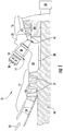
- Fig. 2 provides an enlarged side view and partial cross-section of the combustor 14 shown in Fig. 1 according to a first embodiment of the present invention.
- the combustor casing 32 and end cover 36 define a volume 50, also referred to as the head end, inside the combustor 14, and a liner 52 circumferentially surrounds and defines at least a portion of the combustion chamber 38.
- a flow sleeve 54 may circumferentially surround at least a portion of the combustion chamber 38 to define an inner annular passage 56 between the liner 52 and the flow sleeve 54 and an outer annular passage 58 between the flow sleeve 54 and the casing 32.
- the majority of the compressed working fluid 22 from the compressor 12 may flow through the inner annular passage 56 to provide convective cooling to the liner 24.
- the compressed working fluid 22 reaches the head end or volume 50, the compressed working fluid 22 reverses direction to flow through the fuel nozzles 34 and into the combustion chamber 38.
- the combustor casing 32 may include multiple annular sections that facilitate assembly and/or accommodate thermal expansion during operations.
- the combustor casing 32 may include a first annular casing 60 adjacent to the end cover 36 and a second annular casing 62 upstream from the first annular casing 60.
- a clamp, weld bead, and/or plurality of bolts 64 may circumferentially surround the combustor 14 to provide a connection or joint 66 between the first and second annular casings 60, 62.
- a flange 70 may extend radially between the first and second annular casings 60, 62, and the flange 70 may include one or more internal fluid passages that provide fluid communication through the connection 66.
- the flange 70 may include a fuel passage 72 that extends radially through the casing 32 to provide fluid communication through the casing 32 to the inner annular passage 56.
- a plurality of vanes 74 may circumferentially surround the combustion chamber 38 and extend radially in the annular passage 56 to guide the compressed working fluid 22 flow. In particular embodiments, the vanes 74 may be angled to impart swirl to the compressed working fluid 22 flowing through the inner annular passage 56.
- the flange 70 may connect to one or more of the vanes 74, and the fuel passage 72 may extend inside one or more of the vanes 74 so fuel may flow through quaternary fuel ports 76 in the vanes 74 to mix with the compressed working fluid 22 flowing through the inner annular passage 56.
- the flange 70 may include a diluent passage 78 that provides a fluid pathway for the compressed working fluid 22 to flow from the outer annular passage 58 into or around the fuel nozzles 34 before flowing into the combustion chamber 38.
- the fuel-air mixture flowing into the combustion chamber 38 ignites in a primary reaction zone 80 adjacent to the fuel nozzles 34.
- at least one fuel nozzle such as the center fuel nozzle 84 shown in Fig. 2 , extends axially inside the combustion chamber 38 through the primary reaction zone 80 to a secondary reaction zone 82.
- Various combinations of fuel and/or fluid passages may extend axially inside the center fuel nozzle 84. For example, as shown in the particular embodiment illustrated in Fig.
- a gaseous fuel supply 86 may be connected to a gaseous fuel passage 88 that extends axially inside the center fuel nozzle 84, and/or a liquid fuel supply 90 may be connected to a liquid fuel passage 92 that extends axially inside the center fuel nozzle 84.
- first and/or second fluid passages 94, 96 may extend axially inside the center fuel nozzle 84.
- Compressed working fluid 22 that flows through the inner annular passage 56 into the head end 50 may reverse direction and flow into the first fluid passage 94.
- cooler and higher pressure compressed working fluid 22 that flows through the outer annular passage 58 may flow through the diluent passage 78 and into the second fluid passage 96.
- Fig. 3 provides an enlarged side cross-section view of a portion of the center fuel nozzle 84 shown in Fig. 2 .
- a plurality of fluid injectors 100 are circumferentially arranged inside the center fuel nozzle 84 downstream from the primary reaction zone 80, and each fluid injector 100 defines a longitudinal axis 102 substantially perpendicular to a longitudinal axis 104 defined by the combustion chamber 38.
- the compressed working fluid 22 flowing through the first fluid passage 94 may merge with the fluid injectors 100.
- cooler and higher pressure compressed working fluid 22 flowing through the second fluid passage 96 may flow around the fluid injectors 100 and along a downstream surface 106 of the center fuel nozzle 84 to convectively cool the downstream surface 106 before also merging with the fluid injectors 100.
- the compressed working fluid 22 may then flow through fluid injectors 100 substantially normal to the flow of combustion gases inside the combustion chamber 38 to enhance mixing between the compressed working fluid 22 and the combustion gases to quench the combustion gases downstream from the primary reaction zone 80.
- gaseous and/or liquid fuel may be supplied through the gaseous and liquid fuel passages 88, 92, respectively, to increase the combustion gas temperature.
- the gaseous fuel passage 88 may circumferentially surround one or more of the fluid injectors 100, and a plurality of fuel ports 110 may provide fluid communication between the gaseous fuel passage 88 and one or more of the fluid injectors 100 inside the center fuel nozzle 84.
- a plurality of fuel ports 112 may provide fluid communication between the liquid fuel passage 92 and one or more of the fluid injectors 100 inside the center fuel nozzle 84.
- gaseous and/or liquid fuel may mix with the compressed working fluid 22 supplied by the first and/or second fluid passages 94, 96 inside the fluid injectors 100 to form a lean fuel-air mixture.
- the fluid injectors 100 may then inject the lean fuel-air mixture substantially normal to the flow of combustion gases inside the combustion chamber 38 to enhance mixing between the lean fuel-air mixture and the combustion gases, and the combustion gases ignite the lean fuel-air mixture in the secondary reaction zone 82 to increase the combustion gas temperature.
- the injection of the lean fuel-air mixture from the center fuel nozzle 84 obviates the formation of localized hot streaks along the inside of the combustion chamber 38 and transition piece 40.
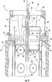
- Fig. 4 provides an enlarged side and partial cross-section view of the combustor 14 shown in Fig. 1 according to a second embodiment of the present invention
- Fig. 5 provides an enlarged side cross-section view of a portion of the center fuel nozzle 84 shown in Fig. 4
- the combustor 14 again includes the casing 32, fuel nozzles 34, liner 52, flow sleeve 54, and inner annular passage 56 as previously described with respect to the embodiment shown in Fig. 2 .
- the center fuel nozzle 84 again extends inside the combustion chamber 38 through the primary reaction zone 80 and includes the gaseous and liquid fuel passages 88, 92, fluid injectors 100, and fuel ports 110, 112 as previously described.
- a plurality of fluid ports 114 through the downstream surface 106 are in fluid communication with the first fluid passage 94.
- a portion of the compressed working fluid 22 flowing through the first fluid passage 94 may flow through the fluid ports 114 to provide effusion cooling to the downstream surface 106 of the center fuel nozzle 84.
- the various combustors shown and described with respect to Figs. 2-5 may also provide a method for supplying fuel to the combustor 14. Such a method is not part of the subject-matter claimed.
- the method may include, for example, supplying at least one of liquid or gaseous fuel through the center fuel nozzle 84 that extends axially inside the combustion chamber 38 through the primary reaction zone 80.
- the method may include mixing the liquid and/or gaseous fuel with the working fluid 22 inside the center fuel nozzle 84 to create the lean fuel-air mixture and injecting the fuel-air mixture substantially normal to the flow of combustion gases through the combustion chamber 38.
- the first fluid passage 94 may provide fluid communication between the inner annular passage 56 and one or more of the fluid injectors 100 inside the center fuel nozzle 84 and/or the second fluid passage 96 may provide fluid communication between the outer annular passage 58 and one or more of the fluid injectors 100 inside the center fuel nozzle 84.
- the various embodiments described herein may supply liquid and/or gaseous fuel for late lean combustion to enhance combustor 14 efficiency without producing a corresponding increase in NOx emissions.
- the various embodiments described herein avoid creating localized hot streaks along the inside of the combustion chamber 38 and transition piece 40 that may reduce the low cycle fatigue limit for these components.
Description
- The present invention generally involves a combustor and method for supplying fuel fluid to a combustor. In particular embodiments, a center fuel nozzle may supply a lean fuel-air mixture to the combustion chamber.
- Combustors are commonly used in industrial and power generation operations to ignite fuel to produce combustion gases having a high temperature and pressure. For example, gas turbines typically include one or more combustors to generate power or thrust. A typical gas turbine used to generate electrical power includes an axial compressor at the front, one or more combustors around the middle, and a turbine at the rear. Ambient air may be supplied to the compressor, and rotating blades and stationary vanes in the compressor progressively impart kinetic energy to the working fluid (air) to produce a compressed working fluid at a highly energized state. The compressed working fluid mixes with fuel before flowing into a combustion chamber where the fuel-air mixture ignites in a primary reaction zone to generate combustion gases having a high temperature and pressure. The combustion gases flow through a transition piece and into the turbine where they expand to produce work. For example, expansion of the combustion gases in the turbine may rotate a shaft connected to a generator to produce electricity.
- Various design and operating parameters influence the design and operation of combustors. For example, higher combustion gas temperatures generally improve the thermodynamic efficiency of the combustor. However, higher combustion gas temperatures also promote flashback or flame holding conditions in which the combustion flame migrates towards the fuel being supplied by fuel nozzles, possibly causing severe damage to the fuel nozzles in a relatively short amount of time. In addition, higher combustion gas temperatures generally increase the disassociation rate of diatomic nitrogen, increasing the production of nitrogen oxides (NOx). Conversely, a lower combustion gas temperature associated with reduced fuel flow and/or part load operation (turndown) generally reduces the chemical reaction rates of the combustion gases, increasing the production of carbon monoxide and unburned hydrocarbons.
- In a particular combustor design, one or more late lean injectors or tubes may be circumferentially arranged around the combustion chamber downstream from the fuel nozzles. A portion of the compressed working fluid exiting the compressor may flow through the tubes to mix with fuel to produce a lean fuel-air mixture. The lean fuel-air mixture may then flow into a secondary reaction zone in the combustion chamber where the combustion gases from the primary reaction zone ignite the lean fuel-air mixture. The additional combustion of the lean fuel-air mixture raises the combustion gas temperature and increases the thermodynamic efficiency of the combustor.
- Although the circumferentially arranged late lean injectors are effective at increasing combustion gas temperatures without producing a corresponding increase in the production of NOx emissions, liquid fuel supplied to the late lean injectors often results in excessive coking in the fuel passages. In addition, the circumferential delivery of the lean fuel-air mixture into the combustion chamber may also create localized hot streaks along the inside of the combustion chamber and transition piece that reduces the low cycle fatigue limit for these components. As a result, a combustor that can supply both liquid and gaseous fuel for late lean combustion without producing localized hot streaks along the inside of the combustion chamber and transition piece would be useful.
- Various aspects and advantages of the invention are set forth below in the following description, or may be clear from the description, or may be learned through practice of the invention.
-
US 2012/011854 suggests a combustor, comprising combustion chamber that defines a longitudinal axis, a primary reaction zone inside the combustion chamber and secondary reaction zone inside the combustion chamber downstream from the primary reaction zone. A center fuel nozzle extends axially inside the combustion chamber. The center fuel nozzle surrounds an end portion of a fuel passage. The nozzle center body is circumferentially surrounded by a burner tube, while the burner tube is circumferentially surrounded by an outer peripheral wall. Substantially radially extending holes are provided at the fuel passage so as to provided fuel to swirling vanes arranged in an annular air passage formed between the nozzle center body and the burner tube. Radially extending cooling holes are provided inside the burner tube. A fuel-air mixture formed inside fuel-air mixing passage between the nozzle center body and the burner tube is axially discharged from a front face of the burner tube and into the secondary reaction zone downstream the center fuel nozzle. - The presently claimed invention relates to a combustor as set forth in the claims.
- An example useful for appreciating the presently claimed invention is a combustor that includes a plurality of fuel nozzles and a combustion chamber downstream from the plurality of fuel nozzles, wherein the combustion chamber defines a longitudinal axis. A primary reaction zone is inside the combustion chamber adjacent to the plurality of fuel nozzles, and a secondary reaction zone inside the combustion chamber is downstream from the primary reaction zone. A center fuel nozzle extends axially inside the combustion chamber through the primary reaction zone, and a plurality of fluid injectors are circumferentially arranged inside the center fuel nozzle downstream from the primary reaction zone. Each fluid injector defines an additional longitudinal axis out of the center fuel nozzle that is substantially perpendicular to the longitudinal axis of the combustion chamber.
- In a still further example useful for appreciating the presently claimed invention, the combustor includes an end cover that extends radially across at least a portion of the combustor, and a plurality of fuel nozzles are radially arranged in the end cover. A combustion chamber downstream from the end cover defines a longitudinal axis. A primary reaction zone is inside the combustion chamber adjacent to the fuel nozzles, and at least one fuel nozzle extends axially inside the combustion chamber downstream from the primary reaction zone. A plurality of fluid injectors are circumferentially arranged inside the at least one fuel nozzle downstream from the primary reaction zone, and each fluid injector defines an additional longitudinal axis out of the at least one fuel nozzle that is substantially perpendicular to the longitudinal axis of the combustion chamber.
- Those of ordinary skill in the art will better appreciate the features and aspects of such embodiments, and others, upon review of the specification.
- Various aspects and embodiments of the present invention will now be described in connection with the accompanying drawings, in which:
-
Fig. 1 is a simplified side cross-section view of an exemplary gas turbine; -
Fig. 2 is an enlarged side and partial cross-section view of the combustor shown inFig. 1 according to a first embodiment of the present invention; -
Fig. 3 is an enlarged side cross-section view of a portion of the center fuel nozzle shown inFig. 2 ; -
Fig. 4 is an enlarged side and partial cross-section view of the combustor shown inFig. 1 according to a second embodiment of the present invention; and -
Fig. 5 is an enlarged side cross-section view of a portion of the center fuel nozzle shown inFig. 4 . - Reference will now be made in detail to present embodiments of the invention, one or more examples of which are illustrated in the accompanying drawings. The detailed description uses numerical and letter designations to refer to features in the drawings. Like or similar designations in the drawings and description have been used to refer to like or similar parts of the invention. As used herein, the terms "first", "second", and "third" may be used interchangeably to distinguish one component from another and are not intended to signify location or importance of the individual components. In addition, the terms "upstream" and "downstream" refer to the relative location of components in a fluid pathway. For example, component A is upstream from component B if a fluid flows from component A to component B. Conversely, component B is downstream from component A if component B receives a fluid flow from component A.
- Each example is provided by way of explanation of the invention, not limitation of the invention. In fact, it will be apparent to those skilled in the art that modifications and variations can be made in the present invention without departing from the scope of the claims.
- Thus, it is intended that embodiments of the present invention cover such modifications and variations as come within the scope of the appended claims
- The combustor generally includes a combustion chamber with a primary reaction zone and a secondary reaction zone downstream from the primary reaction zone. A center fuel nozzle extends axially inside the combustion chamber, and a plurality of fluid injectors are circumferentially arranged inside the center fuel nozzle downstream from the primary reaction zone. Each fluid injector defines a longitudinal axis out of the center fuel nozzle that is substantially perpendicular to the longitudinal axis of the combustion chamber. In particular embodiments, the combustor may further include one or more fuel and/or fluid passages that provide fuel and/or working fluid to the fluid injectors. Although exemplary embodiments of the present invention will be described generally in the context of a combustor incorporated into a gas turbine for purposes of illustration, one of ordinary skill in the art will readily appreciate that embodiments of the present invention may be applied to any combustor and are not limited to a gas turbine combustor unless specifically recited in the claims.
-
Fig. 1 provides a simplified cross-section of anexemplary gas turbine 10 that may incorporate various embodiments of the present invention. As shown, thegas turbine 10 may generally include acompressor 12 at the front, one ormore combustors 14 radially disposed around the middle, and aturbine 16 at the rear. Thecompressor 12 and theturbine 16 typically share acommon rotor 18 connected to agenerator 20 to produce electricity. - The
compressor 12 may be an axial flow compressor in which a workingfluid 22, such as ambient air, enters thecompressor 12 and passes through alternating stages ofstationary vanes 24 and rotatingblades 26. Acompressor casing 28 contains the workingfluid 22 as thestationary vanes 24 and rotatingblades 26 accelerate and redirect the workingfluid 22 to produce a continuous flow of compressed workingfluid 22. The majority of the compressed workingfluid 22 flows through acompressor discharge passage 30 to thecombustor 14. - The
combustor 14 may be any type of combustor known in the art. For example, as shown inFig. 1 , acombustor casing 32 may circumferentially surround some or all of thecombustor 14 to contain the compressed workingfluid 22 flowing from thecompressor 12. One ormore fuel nozzles 34 may be radially arranged in anend cover 36 to supply fuel to acombustion chamber 38 downstream from thefuel nozzles 34. Possible fuels include, for example, one or more of blast furnace gas, coke oven gas, natural gas, vaporized liquefied natural gas (LNG), hydrogen, and propane. The compressed workingfluid 22 may flow from thecompressor discharge passage 30 along the outside of thecombustion chamber 38 before reaching theend cover 36 and reversing direction to flow through thefuel nozzles 34 to mix with the fuel. The mixture of fuel and compressed workingfluid 22 flows into thecombustion chamber 38 where it ignites to generate combustion gases having a high temperature and pressure. The combustion gases flow through atransition piece 40 to theturbine 16. - The
turbine 16 may include alternating stages ofstators 42 androtating buckets 44. The first stage ofstators 42 redirects and focuses the combustion gases onto the first stage ofturbine buckets 44. As the combustion gases pass over the first stage ofturbine buckets 44, the combustion gases expand, causing theturbine buckets 44 androtor 18 to rotate. The combustion gases then flow to the next stage ofstators 42 which redirects the combustion gases to the next stage of rotatingturbine buckets 44, and the process repeats for the following stages. -
Fig. 2 provides an enlarged side view and partial cross-section of thecombustor 14 shown inFig. 1 according to a first embodiment of the present invention. As shown, thecombustor casing 32 and end cover 36 define avolume 50, also referred to as the head end, inside thecombustor 14, and aliner 52 circumferentially surrounds and defines at least a portion of thecombustion chamber 38. Aflow sleeve 54 may circumferentially surround at least a portion of thecombustion chamber 38 to define an innerannular passage 56 between theliner 52 and theflow sleeve 54 and an outerannular passage 58 between theflow sleeve 54 and thecasing 32. In this manner, the majority of the compressed workingfluid 22 from thecompressor 12 may flow through the innerannular passage 56 to provide convective cooling to theliner 24. When the compressed workingfluid 22 reaches the head end orvolume 50, the compressed workingfluid 22 reverses direction to flow through thefuel nozzles 34 and into thecombustion chamber 38. - The
combustor casing 32 may include multiple annular sections that facilitate assembly and/or accommodate thermal expansion during operations. For example, as illustrated in the particular embodiment shown inFig. 2 , thecombustor casing 32 may include a firstannular casing 60 adjacent to theend cover 36 and a secondannular casing 62 upstream from the firstannular casing 60. A clamp, weld bead, and/or plurality of bolts 64 may circumferentially surround thecombustor 14 to provide a connection or joint 66 between the first and secondannular casings - In particular embodiments, a
flange 70 may extend radially between the first and secondannular casings flange 70 may include one or more internal fluid passages that provide fluid communication through theconnection 66. For example, theflange 70 may include afuel passage 72 that extends radially through thecasing 32 to provide fluid communication through thecasing 32 to the innerannular passage 56. A plurality ofvanes 74 may circumferentially surround thecombustion chamber 38 and extend radially in theannular passage 56 to guide the compressed workingfluid 22 flow. In particular embodiments, thevanes 74 may be angled to impart swirl to the compressed workingfluid 22 flowing through the innerannular passage 56. Theflange 70 may connect to one or more of thevanes 74, and thefuel passage 72 may extend inside one or more of thevanes 74 so fuel may flow throughquaternary fuel ports 76 in thevanes 74 to mix with the compressed workingfluid 22 flowing through the innerannular passage 56. Alternately, or in addition, theflange 70 may include adiluent passage 78 that provides a fluid pathway for the compressed workingfluid 22 to flow from the outerannular passage 58 into or around thefuel nozzles 34 before flowing into thecombustion chamber 38. - As shown in
Fig. 2 , the fuel-air mixture flowing into thecombustion chamber 38 ignites in aprimary reaction zone 80 adjacent to thefuel nozzles 34. In addition, at least one fuel nozzle, such as thecenter fuel nozzle 84 shown inFig. 2 , extends axially inside thecombustion chamber 38 through theprimary reaction zone 80 to asecondary reaction zone 82. Various combinations of fuel and/or fluid passages may extend axially inside thecenter fuel nozzle 84. For example, as shown in the particular embodiment illustrated inFig. 2 , agaseous fuel supply 86 may be connected to agaseous fuel passage 88 that extends axially inside thecenter fuel nozzle 84, and/or aliquid fuel supply 90 may be connected to aliquid fuel passage 92 that extends axially inside thecenter fuel nozzle 84. Alternately or in addition, first and/or secondfluid passages center fuel nozzle 84. Compressed workingfluid 22 that flows through the innerannular passage 56 into thehead end 50 may reverse direction and flow into thefirst fluid passage 94. In addition, cooler and higher pressure compressed workingfluid 22 that flows through the outerannular passage 58 may flow through thediluent passage 78 and into thesecond fluid passage 96. -
Fig. 3 provides an enlarged side cross-section view of a portion of thecenter fuel nozzle 84 shown inFig. 2 . As shown inFigs. 2 and3 , a plurality offluid injectors 100 are circumferentially arranged inside thecenter fuel nozzle 84 downstream from theprimary reaction zone 80, and eachfluid injector 100 defines alongitudinal axis 102 substantially perpendicular to alongitudinal axis 104 defined by thecombustion chamber 38. As shown most clearly inFig. 3 , the compressed workingfluid 22 flowing through thefirst fluid passage 94 may merge with thefluid injectors 100. In addition, the cooler and higher pressure compressed workingfluid 22 flowing through thesecond fluid passage 96 may flow around thefluid injectors 100 and along adownstream surface 106 of thecenter fuel nozzle 84 to convectively cool thedownstream surface 106 before also merging with thefluid injectors 100. The compressed workingfluid 22 may then flow throughfluid injectors 100 substantially normal to the flow of combustion gases inside thecombustion chamber 38 to enhance mixing between the compressed workingfluid 22 and the combustion gases to quench the combustion gases downstream from theprimary reaction zone 80. - When desired, gaseous and/or liquid fuel may be supplied through the gaseous and
liquid fuel passages Fig. 3 , at least a portion of thegaseous fuel passage 88 may circumferentially surround one or more of thefluid injectors 100, and a plurality offuel ports 110 may provide fluid communication between thegaseous fuel passage 88 and one or more of thefluid injectors 100 inside thecenter fuel nozzle 84. Alternately or in addition, a plurality offuel ports 112 may provide fluid communication between theliquid fuel passage 92 and one or more of thefluid injectors 100 inside thecenter fuel nozzle 84. In this manner, gaseous and/or liquid fuel may mix with the compressed workingfluid 22 supplied by the first and/or secondfluid passages fluid injectors 100 to form a lean fuel-air mixture. Thefluid injectors 100 may then inject the lean fuel-air mixture substantially normal to the flow of combustion gases inside thecombustion chamber 38 to enhance mixing between the lean fuel-air mixture and the combustion gases, and the combustion gases ignite the lean fuel-air mixture in thesecondary reaction zone 82 to increase the combustion gas temperature. In addition, the injection of the lean fuel-air mixture from thecenter fuel nozzle 84 obviates the formation of localized hot streaks along the inside of thecombustion chamber 38 andtransition piece 40. -
Fig. 4 provides an enlarged side and partial cross-section view of thecombustor 14 shown inFig. 1 according to a second embodiment of the present invention, andFig. 5 provides an enlarged side cross-section view of a portion of thecenter fuel nozzle 84 shown inFig. 4 . As shown inFig. 4 , thecombustor 14 again includes thecasing 32,fuel nozzles 34,liner 52,flow sleeve 54, and innerannular passage 56 as previously described with respect to the embodiment shown inFig. 2 . In addition, thecenter fuel nozzle 84 again extends inside thecombustion chamber 38 through theprimary reaction zone 80 and includes the gaseous andliquid fuel passages fluid injectors 100, andfuel ports Fig. 5 , a plurality offluid ports 114 through thedownstream surface 106 are in fluid communication with thefirst fluid passage 94. As a result, a portion of the compressed workingfluid 22 flowing through thefirst fluid passage 94 may flow through thefluid ports 114 to provide effusion cooling to thedownstream surface 106 of thecenter fuel nozzle 84. - One of ordinary skill in the art will readily appreciate from the teachings herein that the various combustors shown and described with respect to
Figs. 2-5 may also provide a method for supplying fuel to thecombustor 14. Such a method is not part of the subject-matter claimed. The method may include, for example, supplying at least one of liquid or gaseous fuel through thecenter fuel nozzle 84 that extends axially inside thecombustion chamber 38 through theprimary reaction zone 80. In addition, the method may include mixing the liquid and/or gaseous fuel with the workingfluid 22 inside thecenter fuel nozzle 84 to create the lean fuel-air mixture and injecting the fuel-air mixture substantially normal to the flow of combustion gases through thecombustion chamber 38. In particular methods, thefirst fluid passage 94 may provide fluid communication between the innerannular passage 56 and one or more of thefluid injectors 100 inside thecenter fuel nozzle 84 and/or thesecond fluid passage 96 may provide fluid communication between the outerannular passage 58 and one or more of thefluid injectors 100 inside thecenter fuel nozzle 84. - As a result, the various embodiments described herein may supply liquid and/or gaseous fuel for late lean combustion to enhance
combustor 14 efficiency without producing a corresponding increase in NOx emissions. In addition, the various embodiments described herein avoid creating localized hot streaks along the inside of thecombustion chamber 38 andtransition piece 40 that may reduce the low cycle fatigue limit for these components.
Claims (7)
- A combustor (14), comprising:a. a combustion chamber (38) that defines a longitudinal axis;b. a primary reaction zone (80) inside the combustion chamber;c. a secondary reaction zone (82) inside the combustion chamber downstream from the primary reaction zone (80);d. a center fuel nozzle (84) that extends axially inside the combustion chamber (38); ande. a plurality of fluid injectors (100) circumferentially arranged inside the center fuel nozzle (84) downstream from the primary reaction zone (80), wherein each fluid injector (100) defines an additional longitudinal axis (102) out of the center fuel nozzle (84) that is substantially perpendicular to the longitudinal axis of the combustion chamber (38)
wherein the center fuel nozzle (84) extends axially inside the combustion chamber (38) through the primary reaction zone (80) to the secondary reaction zone (82) and the fluid injectors (100) are configured and arranged to discharge one of a compressed working fluid and a fuel-air mixture into the combustion chamber (38),
characterised in that the working fluid or the fuel-air-mixture are discharged substantially normal to the flow of combustion gases inside the combustion chamber. - The combustor (14) as in claim 1, further comprising:a. a first fuel passage (88) that extends axially inside the center fuel nozzle;b. a gaseous fuel supply (86) connected to the first fuel passage; andc. a plurality of fuel ports (110) that provides fluid communication between the first fuel passage and one or more of the fluid injectors inside the center fuel nozzle.
- The combustor (14) as in claim 2, wherein at least a portion of the first fuel passage (88) circumferentially surrounds one or more of the fluid injectors.
- The combustor (14) as in any preceding claim, further comprising:a. a second fuel passage (92) that extends axially inside the center fuel nozzle;b. a liquid fuel supply (90) connected to the second fuel passage; andc. a plurality of fuel ports (112) that provides fluid communication between the second fuel passage (92) and one or more of the fluid injectors (100) inside the center fuel nozzle.
- The combustor (14) as in any preceding claim, further comprising:a. a casing (32) that circumferentially surrounds at least a portion of the combustion chamber;b. a flow sleeve (54) between the casing and the combustion chamber that defines an inner annular passage between the combustion chamber and the flow sleeve and an outer annular passage between the flow sleeve and the casing; andc. a first fluid passage (94) that extends axially inside the center fuel nozzle and provides fluid communication between the inner annular passage and one or more of the fluid injectors inside the center fuel nozzle.
- The combustor (14) as in any preceding claim, further comprising a downstream surface (106) of the center fuel nozzle (84) and a plurality of fluid ports through the downstream surface in fluid communication with the first fluid passage inside the center fuel nozzle.
- The combustor (14) as in any preceding claim, further comprising a second fluid passage (96) that extends axially inside the center fuel nozzle (84) and provides fluid communication between the outer annular passage and one or more of the fluid injectors inside the center fuel nozzle.
Applications Claiming Priority (1)
| Application Number | Priority Date | Filing Date | Title |
|---|---|---|---|
| US13/439,990 US9016039B2 (en) | 2012-04-05 | 2012-04-05 | Combustor and method for supplying fuel to a combustor |
Publications (3)
| Publication Number | Publication Date |
|---|---|
| EP2647911A2 EP2647911A2 (en) | 2013-10-09 |
| EP2647911A3 EP2647911A3 (en) | 2018-07-18 |
| EP2647911B1 true EP2647911B1 (en) | 2020-08-19 |
Family
ID=48013810
Family Applications (1)
| Application Number | Title | Priority Date | Filing Date |
|---|---|---|---|
| EP13161337.4A Active EP2647911B1 (en) | 2012-04-05 | 2013-03-27 | Combustor |
Country Status (5)
| Country | Link |
|---|---|
| US (1) | US9016039B2 (en) |
| EP (1) | EP2647911B1 (en) |
| JP (1) | JP6134559B2 (en) |
| CN (1) | CN103363549B (en) |
| RU (1) | RU2614887C2 (en) |
Families Citing this family (19)
| Publication number | Priority date | Publication date | Assignee | Title |
|---|---|---|---|---|
| US9500367B2 (en) | 2013-11-11 | 2016-11-22 | General Electric Company | Combustion casing manifold for high pressure air delivery to a fuel nozzle pilot system |
| EP3015771B1 (en) * | 2014-10-31 | 2020-01-01 | Ansaldo Energia Switzerland AG | Combustor arrangement for a gas turbine |
| EP3015772B1 (en) * | 2014-10-31 | 2020-01-08 | Ansaldo Energia Switzerland AG | Combustor arrangement for a gas turbine |
| US20170058784A1 (en) * | 2015-08-27 | 2017-03-02 | General Electric Company | System and method for maintaining emissions compliance while operating a gas turbine at turndown condition |
| US20170058771A1 (en) * | 2015-08-27 | 2017-03-02 | General Electric Company | System and method for generating steam during gas turbine low-load conditions |
| US10641175B2 (en) * | 2016-03-25 | 2020-05-05 | General Electric Company | Panel fuel injector |
| CN106402934A (en) * | 2016-11-21 | 2017-02-15 | 深圳智慧能源技术有限公司 | Gas turbine combustion chamber and nozzle thereof |
| CN106439914A (en) * | 2016-11-21 | 2017-02-22 | 深圳智慧能源技术有限公司 | Combustion chamber of combustion gas turbine |
| GB201700459D0 (en) * | 2017-01-11 | 2017-02-22 | Rolls Royce Plc | Fuel injector |
| US10655858B2 (en) * | 2017-06-16 | 2020-05-19 | General Electric Company | Cooling of liquid fuel cartridge in gas turbine combustor head end |
| EP3486570B1 (en) * | 2017-11-15 | 2023-06-21 | Ansaldo Energia Switzerland AG | Second-stage combustor for a sequential combustor of a gas turbine |
| US10989118B2 (en) | 2017-12-20 | 2021-04-27 | Wrightspeed, Inc. | Controlled evaporation and heating of fuels for turbine engines |
| US11174792B2 (en) | 2019-05-21 | 2021-11-16 | General Electric Company | System and method for high frequency acoustic dampers with baffles |
| US11156164B2 (en) | 2019-05-21 | 2021-10-26 | General Electric Company | System and method for high frequency accoustic dampers with caps |
| US11460191B2 (en) | 2020-08-31 | 2022-10-04 | General Electric Company | Cooling insert for a turbomachine |
| US11614233B2 (en) | 2020-08-31 | 2023-03-28 | General Electric Company | Impingement panel support structure and method of manufacture |
| US11371702B2 (en) | 2020-08-31 | 2022-06-28 | General Electric Company | Impingement panel for a turbomachine |
| US11255545B1 (en) | 2020-10-26 | 2022-02-22 | General Electric Company | Integrated combustion nozzle having a unified head end |
| US11767766B1 (en) | 2022-07-29 | 2023-09-26 | General Electric Company | Turbomachine airfoil having impingement cooling passages |
Family Cites Families (35)
| Publication number | Priority date | Publication date | Assignee | Title |
|---|---|---|---|---|
| US5193346A (en) * | 1986-11-25 | 1993-03-16 | General Electric Company | Premixed secondary fuel nozzle with integral swirler |
| US4982570A (en) * | 1986-11-25 | 1991-01-08 | General Electric Company | Premixed pilot nozzle for dry low Nox combustor |
| EP0269824B1 (en) * | 1986-11-25 | 1990-12-19 | General Electric Company | Premixed pilot nozzle for dry low nox combustor |
| JP2544470B2 (en) * | 1989-02-03 | 1996-10-16 | 株式会社日立製作所 | Gas turbine combustor and operating method thereof |
| US5127221A (en) * | 1990-05-03 | 1992-07-07 | General Electric Company | Transpiration cooled throat section for low nox combustor and related process |
| DE69126846T2 (en) * | 1990-11-27 | 1998-02-12 | Gen Electric | Secondary premix fuel nozzle with integrated swirl device |
| JPH06272862A (en) * | 1993-03-18 | 1994-09-27 | Hitachi Ltd | Method and apparatus for mixing fuel into air |
| US5778676A (en) * | 1996-01-02 | 1998-07-14 | General Electric Company | Dual fuel mixer for gas turbine combustor |
| JP2858104B2 (en) * | 1996-02-05 | 1999-02-17 | 三菱重工業株式会社 | Gas turbine combustor |
| US6047550A (en) | 1996-05-02 | 2000-04-11 | General Electric Co. | Premixing dry low NOx emissions combustor with lean direct injection of gas fuel |
| US6502399B2 (en) * | 1997-09-10 | 2003-01-07 | Mitsubishi Heavy Industries, Ltd. | Three-dimensional swirler in a gas turbine combustor |
| US6122916A (en) * | 1998-01-02 | 2000-09-26 | Siemens Westinghouse Power Corporation | Pilot cones for dry low-NOx combustors |
| US6189314B1 (en) * | 1998-09-01 | 2001-02-20 | Honda Giken Kogyo Kabushiki Kaisha | Premix combustor for gas turbine engine |
| JP2001182908A (en) * | 1999-12-22 | 2001-07-06 | Tokyo Gas Co Ltd | LOW NOx BURNR AND METHOD OF COMBUSTION IN LOW NOx BURNER |
| JP2001227709A (en) * | 2000-02-17 | 2001-08-24 | Tokyo Gas Co Ltd | LOW NOx BURNER |
| US6427446B1 (en) * | 2000-09-19 | 2002-08-06 | Power Systems Mfg., Llc | Low NOx emission combustion liner with circumferentially angled film cooling holes |
| US6698207B1 (en) * | 2002-09-11 | 2004-03-02 | Siemens Westinghouse Power Corporation | Flame-holding, single-mode nozzle assembly with tip cooling |
| DE102004049491A1 (en) * | 2004-10-11 | 2006-04-20 | Alstom Technology Ltd | premix |
| US8511097B2 (en) * | 2005-03-18 | 2013-08-20 | Kawasaki Jukogyo Kabushiki Kaisha | Gas turbine combustor and ignition method of igniting fuel mixture in the same |
| CN101365913A (en) * | 2005-11-04 | 2009-02-11 | 阿尔斯托姆科技有限公司 | Fuel lance |
| JP4959620B2 (en) * | 2007-04-26 | 2012-06-27 | 株式会社日立製作所 | Combustor and fuel supply method for combustor |
| EP2179222B2 (en) * | 2007-08-07 | 2021-12-01 | Ansaldo Energia IP UK Limited | Burner for a combustion chamber of a turbo group |
| JP4959524B2 (en) * | 2007-11-29 | 2012-06-27 | 三菱重工業株式会社 | Burning burner |
| EP2119964B1 (en) * | 2008-05-15 | 2018-10-31 | Ansaldo Energia IP UK Limited | Method for reducing emissons from a combustor |
| US8281595B2 (en) * | 2008-05-28 | 2012-10-09 | General Electric Company | Fuse for flame holding abatement in premixer of combustion chamber of gas turbine and associated method |
| EP2208927B1 (en) * | 2009-01-15 | 2016-03-23 | Alstom Technology Ltd | Burner of a gas turbine |
| US20100192582A1 (en) * | 2009-02-04 | 2010-08-05 | Robert Bland | Combustor nozzle |
| US8079218B2 (en) * | 2009-05-21 | 2011-12-20 | General Electric Company | Method and apparatus for combustor nozzle with flameholding protection |
| US20110005189A1 (en) * | 2009-07-08 | 2011-01-13 | General Electric Company | Active Control of Flame Holding and Flashback in Turbine Combustor Fuel Nozzle |
| US20110131998A1 (en) * | 2009-12-08 | 2011-06-09 | Vaibhav Nadkarni | Fuel injection in secondary fuel nozzle |
| US20110225947A1 (en) * | 2010-03-17 | 2011-09-22 | Benjamin Paul Lacy | System and methods for altering air flow in a combustor |
| US8671691B2 (en) * | 2010-05-26 | 2014-03-18 | General Electric Company | Hybrid prefilming airblast, prevaporizing, lean-premixing dual-fuel nozzle for gas turbine combustor |
| US8959921B2 (en) * | 2010-07-13 | 2015-02-24 | General Electric Company | Flame tolerant secondary fuel nozzle |
| US8464537B2 (en) * | 2010-10-21 | 2013-06-18 | General Electric Company | Fuel nozzle for combustor |
| US8966909B2 (en) * | 2012-08-21 | 2015-03-03 | General Electric Company | System for reducing combustion dynamics |
-
2012
- 2012-04-05 US US13/439,990 patent/US9016039B2/en active Active
-
2013
- 2013-03-27 EP EP13161337.4A patent/EP2647911B1/en active Active
- 2013-04-03 JP JP2013077311A patent/JP6134559B2/en not_active Expired - Fee Related
- 2013-04-03 CN CN201310113971.2A patent/CN103363549B/en not_active Expired - Fee Related
- 2013-04-04 RU RU2013114997A patent/RU2614887C2/en not_active IP Right Cessation
Non-Patent Citations (1)
| Title |
|---|
| None * |
Also Published As
| Publication number | Publication date |
|---|---|
| CN103363549A (en) | 2013-10-23 |
| EP2647911A3 (en) | 2018-07-18 |
| US9016039B2 (en) | 2015-04-28 |
| US20130263571A1 (en) | 2013-10-10 |
| RU2013114997A (en) | 2014-10-10 |
| EP2647911A2 (en) | 2013-10-09 |
| RU2614887C2 (en) | 2017-03-30 |
| JP2013217637A (en) | 2013-10-24 |
| CN103363549B (en) | 2016-08-03 |
| JP6134559B2 (en) | 2017-05-24 |
Similar Documents
| Publication | Publication Date | Title |
|---|---|---|
| EP2647911B1 (en) | Combustor | |
| EP2639508B1 (en) | System for supplying a working fluid to a combustor | |
| EP2657611B1 (en) | System for supplying fuel to a combustor | |
| EP2639507B1 (en) | System for supplying a working fluid to a combustor | |
| US8904798B2 (en) | Combustor | |
| US9284888B2 (en) | System for supplying fuel to late-lean fuel injectors of a combustor | |
| US8966909B2 (en) | System for reducing combustion dynamics | |
| US9032704B2 (en) | System for reducing combustion dynamics | |
| US8677753B2 (en) | System for supplying a working fluid to a combustor | |
| US9371989B2 (en) | Combustor nozzle and method for supplying fuel to a combustor | |
| EP2520857A1 (en) | A Combustor Nozzle And Method For Supplying Fuel To A Combustor | |
| US8745986B2 (en) | System and method of supplying fuel to a gas turbine | |
| US20130283802A1 (en) | Combustor | |
| EP2634488A1 (en) | System and method for reducing combustion dynamics in a combustor | |
| EP2592345B1 (en) | Combustor and method for supplying fuel to a combustor | |
| US9188337B2 (en) | System and method for supplying a working fluid to a combustor via a non-uniform distribution manifold |
Legal Events
| Date | Code | Title | Description |
|---|---|---|---|
| PUAI | Public reference made under article 153(3) epc to a published international application that has entered the european phase |
Free format text: ORIGINAL CODE: 0009012 |
|
| AK | Designated contracting states |
Kind code of ref document: A2 Designated state(s): AL AT BE BG CH CY CZ DE DK EE ES FI FR GB GR HR HU IE IS IT LI LT LU LV MC MK MT NL NO PL PT RO RS SE SI SK SM TR |
|
| AX | Request for extension of the european patent |
Extension state: BA ME |
|
| PUAL | Search report despatched |
Free format text: ORIGINAL CODE: 0009013 |
|
| AK | Designated contracting states |
Kind code of ref document: A3 Designated state(s): AL AT BE BG CH CY CZ DE DK EE ES FI FR GB GR HR HU IE IS IT LI LT LU LV MC MK MT NL NO PL PT RO RS SE SI SK SM TR |
|
| AX | Request for extension of the european patent |
Extension state: BA ME |
|
| RIC1 | Information provided on ipc code assigned before grant |
Ipc: F23C 6/04 20060101ALI20180612BHEP Ipc: F23R 3/34 20060101AFI20180612BHEP |
|
| STAA | Information on the status of an ep patent application or granted ep patent |
Free format text: STATUS: REQUEST FOR EXAMINATION WAS MADE |
|
| 17P | Request for examination filed |
Effective date: 20190118 |
|
| RBV | Designated contracting states (corrected) |
Designated state(s): AL AT BE BG CH CY CZ DE DK EE ES FI FR GB GR HR HU IE IS IT LI LT LU LV MC MK MT NL NO PL PT RO RS SE SI SK SM TR |
|
| STAA | Information on the status of an ep patent application or granted ep patent |
Free format text: STATUS: EXAMINATION IS IN PROGRESS |
|
| 17Q | First examination report despatched |
Effective date: 20190417 |
|
| GRAP | Despatch of communication of intention to grant a patent |
Free format text: ORIGINAL CODE: EPIDOSNIGR1 |
|
| STAA | Information on the status of an ep patent application or granted ep patent |
Free format text: STATUS: GRANT OF PATENT IS INTENDED |
|
| INTG | Intention to grant announced |
Effective date: 20200320 |
|
| GRAS | Grant fee paid |
Free format text: ORIGINAL CODE: EPIDOSNIGR3 |
|
| GRAA | (expected) grant |
Free format text: ORIGINAL CODE: 0009210 |
|
| STAA | Information on the status of an ep patent application or granted ep patent |
Free format text: STATUS: THE PATENT HAS BEEN GRANTED |
|
| AK | Designated contracting states |
Kind code of ref document: B1 Designated state(s): AL AT BE BG CH CY CZ DE DK EE ES FI FR GB GR HR HU IE IS IT LI LT LU LV MC MK MT NL NO PL PT RO RS SE SI SK SM TR |
|
| REG | Reference to a national code |
Ref country code: GB Ref legal event code: FG4D |
|
| REG | Reference to a national code |
Ref country code: CH Ref legal event code: EP |
|
| REG | Reference to a national code |
Ref country code: DE Ref legal event code: R096 Ref document number: 602013071702 Country of ref document: DE |
|
| REG | Reference to a national code |
Ref country code: AT Ref legal event code: REF Ref document number: 1304356 Country of ref document: AT Kind code of ref document: T Effective date: 20200915 |
|
| REG | Reference to a national code |
Ref country code: IE Ref legal event code: FG4D |
|
| REG | Reference to a national code |
Ref country code: LT Ref legal event code: MG4D |
|
| REG | Reference to a national code |
Ref country code: NL Ref legal event code: MP Effective date: 20200819 |
|
| PG25 | Lapsed in a contracting state [announced via postgrant information from national office to epo] |
Ref country code: BG Free format text: LAPSE BECAUSE OF FAILURE TO SUBMIT A TRANSLATION OF THE DESCRIPTION OR TO PAY THE FEE WITHIN THE PRESCRIBED TIME-LIMIT Effective date: 20201119 Ref country code: LT Free format text: LAPSE BECAUSE OF FAILURE TO SUBMIT A TRANSLATION OF THE DESCRIPTION OR TO PAY THE FEE WITHIN THE PRESCRIBED TIME-LIMIT Effective date: 20200819 Ref country code: GR Free format text: LAPSE BECAUSE OF FAILURE TO SUBMIT A TRANSLATION OF THE DESCRIPTION OR TO PAY THE FEE WITHIN THE PRESCRIBED TIME-LIMIT Effective date: 20201120 Ref country code: PT Free format text: LAPSE BECAUSE OF FAILURE TO SUBMIT A TRANSLATION OF THE DESCRIPTION OR TO PAY THE FEE WITHIN THE PRESCRIBED TIME-LIMIT Effective date: 20201221 Ref country code: HR Free format text: LAPSE BECAUSE OF FAILURE TO SUBMIT A TRANSLATION OF THE DESCRIPTION OR TO PAY THE FEE WITHIN THE PRESCRIBED TIME-LIMIT Effective date: 20200819 Ref country code: SE Free format text: LAPSE BECAUSE OF FAILURE TO SUBMIT A TRANSLATION OF THE DESCRIPTION OR TO PAY THE FEE WITHIN THE PRESCRIBED TIME-LIMIT Effective date: 20200819 Ref country code: NO Free format text: LAPSE BECAUSE OF FAILURE TO SUBMIT A TRANSLATION OF THE DESCRIPTION OR TO PAY THE FEE WITHIN THE PRESCRIBED TIME-LIMIT Effective date: 20201119 Ref country code: FI Free format text: LAPSE BECAUSE OF FAILURE TO SUBMIT A TRANSLATION OF THE DESCRIPTION OR TO PAY THE FEE WITHIN THE PRESCRIBED TIME-LIMIT Effective date: 20200819 |
|
| REG | Reference to a national code |
Ref country code: AT Ref legal event code: MK05 Ref document number: 1304356 Country of ref document: AT Kind code of ref document: T Effective date: 20200819 |
|
| PG25 | Lapsed in a contracting state [announced via postgrant information from national office to epo] |
Ref country code: PL Free format text: LAPSE BECAUSE OF FAILURE TO SUBMIT A TRANSLATION OF THE DESCRIPTION OR TO PAY THE FEE WITHIN THE PRESCRIBED TIME-LIMIT Effective date: 20200819 Ref country code: RS Free format text: LAPSE BECAUSE OF FAILURE TO SUBMIT A TRANSLATION OF THE DESCRIPTION OR TO PAY THE FEE WITHIN THE PRESCRIBED TIME-LIMIT Effective date: 20200819 Ref country code: NL Free format text: LAPSE BECAUSE OF FAILURE TO SUBMIT A TRANSLATION OF THE DESCRIPTION OR TO PAY THE FEE WITHIN THE PRESCRIBED TIME-LIMIT Effective date: 20200819 Ref country code: LV Free format text: LAPSE BECAUSE OF FAILURE TO SUBMIT A TRANSLATION OF THE DESCRIPTION OR TO PAY THE FEE WITHIN THE PRESCRIBED TIME-LIMIT Effective date: 20200819 Ref country code: IS Free format text: LAPSE BECAUSE OF FAILURE TO SUBMIT A TRANSLATION OF THE DESCRIPTION OR TO PAY THE FEE WITHIN THE PRESCRIBED TIME-LIMIT Effective date: 20201219 |
|
| PG25 | Lapsed in a contracting state [announced via postgrant information from national office to epo] |
Ref country code: RO Free format text: LAPSE BECAUSE OF FAILURE TO SUBMIT A TRANSLATION OF THE DESCRIPTION OR TO PAY THE FEE WITHIN THE PRESCRIBED TIME-LIMIT Effective date: 20200819 Ref country code: SM Free format text: LAPSE BECAUSE OF FAILURE TO SUBMIT A TRANSLATION OF THE DESCRIPTION OR TO PAY THE FEE WITHIN THE PRESCRIBED TIME-LIMIT Effective date: 20200819 Ref country code: CZ Free format text: LAPSE BECAUSE OF FAILURE TO SUBMIT A TRANSLATION OF THE DESCRIPTION OR TO PAY THE FEE WITHIN THE PRESCRIBED TIME-LIMIT Effective date: 20200819 Ref country code: EE Free format text: LAPSE BECAUSE OF FAILURE TO SUBMIT A TRANSLATION OF THE DESCRIPTION OR TO PAY THE FEE WITHIN THE PRESCRIBED TIME-LIMIT Effective date: 20200819 Ref country code: DK Free format text: LAPSE BECAUSE OF FAILURE TO SUBMIT A TRANSLATION OF THE DESCRIPTION OR TO PAY THE FEE WITHIN THE PRESCRIBED TIME-LIMIT Effective date: 20200819 |
|
| REG | Reference to a national code |
Ref country code: DE Ref legal event code: R097 Ref document number: 602013071702 Country of ref document: DE |
|
| PG25 | Lapsed in a contracting state [announced via postgrant information from national office to epo] |
Ref country code: ES Free format text: LAPSE BECAUSE OF FAILURE TO SUBMIT A TRANSLATION OF THE DESCRIPTION OR TO PAY THE FEE WITHIN THE PRESCRIBED TIME-LIMIT Effective date: 20200819 Ref country code: AT Free format text: LAPSE BECAUSE OF FAILURE TO SUBMIT A TRANSLATION OF THE DESCRIPTION OR TO PAY THE FEE WITHIN THE PRESCRIBED TIME-LIMIT Effective date: 20200819 Ref country code: AL Free format text: LAPSE BECAUSE OF FAILURE TO SUBMIT A TRANSLATION OF THE DESCRIPTION OR TO PAY THE FEE WITHIN THE PRESCRIBED TIME-LIMIT Effective date: 20200819 |
|
| PLBE | No opposition filed within time limit |
Free format text: ORIGINAL CODE: 0009261 |
|
| STAA | Information on the status of an ep patent application or granted ep patent |
Free format text: STATUS: NO OPPOSITION FILED WITHIN TIME LIMIT |
|
| PG25 | Lapsed in a contracting state [announced via postgrant information from national office to epo] |
Ref country code: SK Free format text: LAPSE BECAUSE OF FAILURE TO SUBMIT A TRANSLATION OF THE DESCRIPTION OR TO PAY THE FEE WITHIN THE PRESCRIBED TIME-LIMIT Effective date: 20200819 |
|
| 26N | No opposition filed |
Effective date: 20210520 |
|
| PG25 | Lapsed in a contracting state [announced via postgrant information from national office to epo] |
Ref country code: IT Free format text: LAPSE BECAUSE OF FAILURE TO SUBMIT A TRANSLATION OF THE DESCRIPTION OR TO PAY THE FEE WITHIN THE PRESCRIBED TIME-LIMIT Effective date: 20200819 |
|
| PG25 | Lapsed in a contracting state [announced via postgrant information from national office to epo] |
Ref country code: SI Free format text: LAPSE BECAUSE OF FAILURE TO SUBMIT A TRANSLATION OF THE DESCRIPTION OR TO PAY THE FEE WITHIN THE PRESCRIBED TIME-LIMIT Effective date: 20200819 |
|
| PG25 | Lapsed in a contracting state [announced via postgrant information from national office to epo] |
Ref country code: MC Free format text: LAPSE BECAUSE OF FAILURE TO SUBMIT A TRANSLATION OF THE DESCRIPTION OR TO PAY THE FEE WITHIN THE PRESCRIBED TIME-LIMIT Effective date: 20200819 |
|
| REG | Reference to a national code |
Ref country code: CH Ref legal event code: PL |
|
| GBPC | Gb: european patent ceased through non-payment of renewal fee |
Effective date: 20210327 |
|
| REG | Reference to a national code |
Ref country code: BE Ref legal event code: MM Effective date: 20210331 |
|
| PG25 | Lapsed in a contracting state [announced via postgrant information from national office to epo] |
Ref country code: FR Free format text: LAPSE BECAUSE OF NON-PAYMENT OF DUE FEES Effective date: 20210331 Ref country code: GB Free format text: LAPSE BECAUSE OF NON-PAYMENT OF DUE FEES Effective date: 20210327 Ref country code: IE Free format text: LAPSE BECAUSE OF NON-PAYMENT OF DUE FEES Effective date: 20210327 Ref country code: LU Free format text: LAPSE BECAUSE OF NON-PAYMENT OF DUE FEES Effective date: 20210327 Ref country code: LI Free format text: LAPSE BECAUSE OF NON-PAYMENT OF DUE FEES Effective date: 20210331 Ref country code: CH Free format text: LAPSE BECAUSE OF NON-PAYMENT OF DUE FEES Effective date: 20210331 |
|
| PGFP | Annual fee paid to national office [announced via postgrant information from national office to epo] |
Ref country code: DE Payment date: 20220217 Year of fee payment: 10 |
|
| PG25 | Lapsed in a contracting state [announced via postgrant information from national office to epo] |
Ref country code: BE Free format text: LAPSE BECAUSE OF NON-PAYMENT OF DUE FEES Effective date: 20210331 |
|
| PG25 | Lapsed in a contracting state [announced via postgrant information from national office to epo] |
Ref country code: HU Free format text: LAPSE BECAUSE OF FAILURE TO SUBMIT A TRANSLATION OF THE DESCRIPTION OR TO PAY THE FEE WITHIN THE PRESCRIBED TIME-LIMIT; INVALID AB INITIO Effective date: 20130327 |
|
| PG25 | Lapsed in a contracting state [announced via postgrant information from national office to epo] |
Ref country code: CY Free format text: LAPSE BECAUSE OF FAILURE TO SUBMIT A TRANSLATION OF THE DESCRIPTION OR TO PAY THE FEE WITHIN THE PRESCRIBED TIME-LIMIT Effective date: 20200819 |
|
| REG | Reference to a national code |
Ref country code: DE Ref legal event code: R119 Ref document number: 602013071702 Country of ref document: DE |
|
| PG25 | Lapsed in a contracting state [announced via postgrant information from national office to epo] |
Ref country code: DE Free format text: LAPSE BECAUSE OF NON-PAYMENT OF DUE FEES Effective date: 20231003 |