WO2018180519A1 - Vehicle control device - Google Patents
Vehicle control device Download PDFInfo
- Publication number
- WO2018180519A1 WO2018180519A1 PCT/JP2018/010110 JP2018010110W WO2018180519A1 WO 2018180519 A1 WO2018180519 A1 WO 2018180519A1 JP 2018010110 W JP2018010110 W JP 2018010110W WO 2018180519 A1 WO2018180519 A1 WO 2018180519A1
- Authority
- WO
- WIPO (PCT)
- Prior art keywords
- vehicle
- brake
- bbw
- shift
- automatic operation
- Prior art date
Links
Images


Classifications
-
- B—PERFORMING OPERATIONS; TRANSPORTING
- B60—VEHICLES IN GENERAL
- B60T—VEHICLE BRAKE CONTROL SYSTEMS OR PARTS THEREOF; BRAKE CONTROL SYSTEMS OR PARTS THEREOF, IN GENERAL; ARRANGEMENT OF BRAKING ELEMENTS ON VEHICLES IN GENERAL; PORTABLE DEVICES FOR PREVENTING UNWANTED MOVEMENT OF VEHICLES; VEHICLE MODIFICATIONS TO FACILITATE COOLING OF BRAKES
- B60T7/00—Brake-action initiating means
- B60T7/02—Brake-action initiating means for personal initiation
- B60T7/04—Brake-action initiating means for personal initiation foot actuated
- B60T7/045—Brake-action initiating means for personal initiation foot actuated with locking and release means, e.g. providing parking brake application
-
- B—PERFORMING OPERATIONS; TRANSPORTING
- B60—VEHICLES IN GENERAL
- B60T—VEHICLE BRAKE CONTROL SYSTEMS OR PARTS THEREOF; BRAKE CONTROL SYSTEMS OR PARTS THEREOF, IN GENERAL; ARRANGEMENT OF BRAKING ELEMENTS ON VEHICLES IN GENERAL; PORTABLE DEVICES FOR PREVENTING UNWANTED MOVEMENT OF VEHICLES; VEHICLE MODIFICATIONS TO FACILITATE COOLING OF BRAKES
- B60T1/00—Arrangements of braking elements, i.e. of those parts where braking effect occurs specially for vehicles
- B60T1/005—Arrangements of braking elements, i.e. of those parts where braking effect occurs specially for vehicles by locking of wheel or transmission rotation
-
- B—PERFORMING OPERATIONS; TRANSPORTING
- B60—VEHICLES IN GENERAL
- B60T—VEHICLE BRAKE CONTROL SYSTEMS OR PARTS THEREOF; BRAKE CONTROL SYSTEMS OR PARTS THEREOF, IN GENERAL; ARRANGEMENT OF BRAKING ELEMENTS ON VEHICLES IN GENERAL; PORTABLE DEVICES FOR PREVENTING UNWANTED MOVEMENT OF VEHICLES; VEHICLE MODIFICATIONS TO FACILITATE COOLING OF BRAKES
- B60T1/00—Arrangements of braking elements, i.e. of those parts where braking effect occurs specially for vehicles
- B60T1/02—Arrangements of braking elements, i.e. of those parts where braking effect occurs specially for vehicles acting by retarding wheels
- B60T1/06—Arrangements of braking elements, i.e. of those parts where braking effect occurs specially for vehicles acting by retarding wheels acting otherwise than on tread, e.g. employing rim, drum, disc, or transmission or on double wheels
- B60T1/062—Arrangements of braking elements, i.e. of those parts where braking effect occurs specially for vehicles acting by retarding wheels acting otherwise than on tread, e.g. employing rim, drum, disc, or transmission or on double wheels acting on transmission parts
-
- B—PERFORMING OPERATIONS; TRANSPORTING
- B60—VEHICLES IN GENERAL
- B60T—VEHICLE BRAKE CONTROL SYSTEMS OR PARTS THEREOF; BRAKE CONTROL SYSTEMS OR PARTS THEREOF, IN GENERAL; ARRANGEMENT OF BRAKING ELEMENTS ON VEHICLES IN GENERAL; PORTABLE DEVICES FOR PREVENTING UNWANTED MOVEMENT OF VEHICLES; VEHICLE MODIFICATIONS TO FACILITATE COOLING OF BRAKES
- B60T13/00—Transmitting braking action from initiating means to ultimate brake actuator with power assistance or drive; Brake systems incorporating such transmitting means, e.g. air-pressure brake systems
- B60T13/10—Transmitting braking action from initiating means to ultimate brake actuator with power assistance or drive; Brake systems incorporating such transmitting means, e.g. air-pressure brake systems with fluid assistance, drive, or release
- B60T13/66—Electrical control in fluid-pressure brake systems
- B60T13/662—Electrical control in fluid-pressure brake systems characterised by specified functions of the control system components
-
- B—PERFORMING OPERATIONS; TRANSPORTING
- B60—VEHICLES IN GENERAL
- B60T—VEHICLE BRAKE CONTROL SYSTEMS OR PARTS THEREOF; BRAKE CONTROL SYSTEMS OR PARTS THEREOF, IN GENERAL; ARRANGEMENT OF BRAKING ELEMENTS ON VEHICLES IN GENERAL; PORTABLE DEVICES FOR PREVENTING UNWANTED MOVEMENT OF VEHICLES; VEHICLE MODIFICATIONS TO FACILITATE COOLING OF BRAKES
- B60T7/00—Brake-action initiating means
- B60T7/02—Brake-action initiating means for personal initiation
- B60T7/08—Brake-action initiating means for personal initiation hand actuated
- B60T7/10—Disposition of hand control
- B60T7/102—Disposition of hand control by means of a tilting lever
- B60T7/104—Disposition of hand control by means of a tilting lever with a locking mechanism
-
- B—PERFORMING OPERATIONS; TRANSPORTING
- B60—VEHICLES IN GENERAL
- B60T—VEHICLE BRAKE CONTROL SYSTEMS OR PARTS THEREOF; BRAKE CONTROL SYSTEMS OR PARTS THEREOF, IN GENERAL; ARRANGEMENT OF BRAKING ELEMENTS ON VEHICLES IN GENERAL; PORTABLE DEVICES FOR PREVENTING UNWANTED MOVEMENT OF VEHICLES; VEHICLE MODIFICATIONS TO FACILITATE COOLING OF BRAKES
- B60T7/00—Brake-action initiating means
- B60T7/12—Brake-action initiating means for automatic initiation; for initiation not subject to will of driver or passenger
- B60T7/122—Brake-action initiating means for automatic initiation; for initiation not subject to will of driver or passenger for locking of reverse movement
-
- B—PERFORMING OPERATIONS; TRANSPORTING
- B60—VEHICLES IN GENERAL
- B60W—CONJOINT CONTROL OF VEHICLE SUB-UNITS OF DIFFERENT TYPE OR DIFFERENT FUNCTION; CONTROL SYSTEMS SPECIALLY ADAPTED FOR HYBRID VEHICLES; ROAD VEHICLE DRIVE CONTROL SYSTEMS FOR PURPOSES NOT RELATED TO THE CONTROL OF A PARTICULAR SUB-UNIT
- B60W10/00—Conjoint control of vehicle sub-units of different type or different function
- B60W10/18—Conjoint control of vehicle sub-units of different type or different function including control of braking systems
- B60W10/182—Conjoint control of vehicle sub-units of different type or different function including control of braking systems including control of parking brakes
-
- B—PERFORMING OPERATIONS; TRANSPORTING
- B60—VEHICLES IN GENERAL
- B60W—CONJOINT CONTROL OF VEHICLE SUB-UNITS OF DIFFERENT TYPE OR DIFFERENT FUNCTION; CONTROL SYSTEMS SPECIALLY ADAPTED FOR HYBRID VEHICLES; ROAD VEHICLE DRIVE CONTROL SYSTEMS FOR PURPOSES NOT RELATED TO THE CONTROL OF A PARTICULAR SUB-UNIT
- B60W30/00—Purposes of road vehicle drive control systems not related to the control of a particular sub-unit, e.g. of systems using conjoint control of vehicle sub-units, or advanced driver assistance systems for ensuring comfort, stability and safety or drive control systems for propelling or retarding the vehicle
- B60W30/18—Propelling the vehicle
- B60W30/18009—Propelling the vehicle related to particular drive situations
- B60W30/18109—Braking
- B60W30/18118—Hill holding
-
- F—MECHANICAL ENGINEERING; LIGHTING; HEATING; WEAPONS; BLASTING
- F16—ENGINEERING ELEMENTS AND UNITS; GENERAL MEASURES FOR PRODUCING AND MAINTAINING EFFECTIVE FUNCTIONING OF MACHINES OR INSTALLATIONS; THERMAL INSULATION IN GENERAL
- F16D—COUPLINGS FOR TRANSMITTING ROTATION; CLUTCHES; BRAKES
- F16D63/00—Brakes not otherwise provided for; Brakes combining more than one of the types of groups F16D49/00 - F16D61/00
- F16D63/006—Positive locking brakes
-
- F—MECHANICAL ENGINEERING; LIGHTING; HEATING; WEAPONS; BLASTING
- F16—ENGINEERING ELEMENTS AND UNITS; GENERAL MEASURES FOR PRODUCING AND MAINTAINING EFFECTIVE FUNCTIONING OF MACHINES OR INSTALLATIONS; THERMAL INSULATION IN GENERAL
- F16H—GEARING
- F16H59/00—Control inputs to control units of change-speed-, or reversing-gearings for conveying rotary motion
- F16H59/60—Inputs being a function of ambient conditions
- F16H59/66—Road conditions, e.g. slope, slippery
-
- F—MECHANICAL ENGINEERING; LIGHTING; HEATING; WEAPONS; BLASTING
- F16—ENGINEERING ELEMENTS AND UNITS; GENERAL MEASURES FOR PRODUCING AND MAINTAINING EFFECTIVE FUNCTIONING OF MACHINES OR INSTALLATIONS; THERMAL INSULATION IN GENERAL
- F16H—GEARING
- F16H61/00—Control functions within control units of change-speed- or reversing-gearings for conveying rotary motion ; Control of exclusively fluid gearing, friction gearing, gearings with endless flexible members or other particular types of gearing
- F16H61/02—Control functions within control units of change-speed- or reversing-gearings for conveying rotary motion ; Control of exclusively fluid gearing, friction gearing, gearings with endless flexible members or other particular types of gearing characterised by the signals used
-
- F—MECHANICAL ENGINEERING; LIGHTING; HEATING; WEAPONS; BLASTING
- F16—ENGINEERING ELEMENTS AND UNITS; GENERAL MEASURES FOR PRODUCING AND MAINTAINING EFFECTIVE FUNCTIONING OF MACHINES OR INSTALLATIONS; THERMAL INSULATION IN GENERAL
- F16H—GEARING
- F16H61/00—Control functions within control units of change-speed- or reversing-gearings for conveying rotary motion ; Control of exclusively fluid gearing, friction gearing, gearings with endless flexible members or other particular types of gearing
- F16H61/22—Locking of the control input devices
-
- F—MECHANICAL ENGINEERING; LIGHTING; HEATING; WEAPONS; BLASTING
- F16—ENGINEERING ELEMENTS AND UNITS; GENERAL MEASURES FOR PRODUCING AND MAINTAINING EFFECTIVE FUNCTIONING OF MACHINES OR INSTALLATIONS; THERMAL INSULATION IN GENERAL
- F16H—GEARING
- F16H61/00—Control functions within control units of change-speed- or reversing-gearings for conveying rotary motion ; Control of exclusively fluid gearing, friction gearing, gearings with endless flexible members or other particular types of gearing
- F16H61/26—Generation or transmission of movements for final actuating mechanisms
- F16H61/28—Generation or transmission of movements for final actuating mechanisms with at least one movement of the final actuating mechanism being caused by a non-mechanical force, e.g. power-assisted
-
- F—MECHANICAL ENGINEERING; LIGHTING; HEATING; WEAPONS; BLASTING
- F16—ENGINEERING ELEMENTS AND UNITS; GENERAL MEASURES FOR PRODUCING AND MAINTAINING EFFECTIVE FUNCTIONING OF MACHINES OR INSTALLATIONS; THERMAL INSULATION IN GENERAL
- F16H—GEARING
- F16H63/00—Control outputs from the control unit to change-speed- or reversing-gearings for conveying rotary motion or to other devices than the final output mechanism
- F16H63/02—Final output mechanisms therefor; Actuating means for the final output mechanisms
- F16H63/30—Constructional features of the final output mechanisms
- F16H63/34—Locking or disabling mechanisms
-
- F—MECHANICAL ENGINEERING; LIGHTING; HEATING; WEAPONS; BLASTING
- F16—ENGINEERING ELEMENTS AND UNITS; GENERAL MEASURES FOR PRODUCING AND MAINTAINING EFFECTIVE FUNCTIONING OF MACHINES OR INSTALLATIONS; THERMAL INSULATION IN GENERAL
- F16H—GEARING
- F16H63/00—Control outputs from the control unit to change-speed- or reversing-gearings for conveying rotary motion or to other devices than the final output mechanism
- F16H63/40—Control outputs from the control unit to change-speed- or reversing-gearings for conveying rotary motion or to other devices than the final output mechanism comprising signals other than signals for actuating the final output mechanisms
- F16H63/48—Signals to a parking brake or parking lock; Control of parking locks or brakes being part of the transmission
-
- B—PERFORMING OPERATIONS; TRANSPORTING
- B60—VEHICLES IN GENERAL
- B60W—CONJOINT CONTROL OF VEHICLE SUB-UNITS OF DIFFERENT TYPE OR DIFFERENT FUNCTION; CONTROL SYSTEMS SPECIALLY ADAPTED FOR HYBRID VEHICLES; ROAD VEHICLE DRIVE CONTROL SYSTEMS FOR PURPOSES NOT RELATED TO THE CONTROL OF A PARTICULAR SUB-UNIT
- B60W2710/00—Output or target parameters relating to a particular sub-units
- B60W2710/18—Braking system
- B60W2710/186—Status of parking brakes
-
- B—PERFORMING OPERATIONS; TRANSPORTING
- B60—VEHICLES IN GENERAL
- B60W—CONJOINT CONTROL OF VEHICLE SUB-UNITS OF DIFFERENT TYPE OR DIFFERENT FUNCTION; CONTROL SYSTEMS SPECIALLY ADAPTED FOR HYBRID VEHICLES; ROAD VEHICLE DRIVE CONTROL SYSTEMS FOR PURPOSES NOT RELATED TO THE CONTROL OF A PARTICULAR SUB-UNIT
- B60W2710/00—Output or target parameters relating to a particular sub-units
- B60W2710/18—Braking system
- B60W2710/188—Parking lock mechanisms
Definitions
- This disclosure relates to a vehicle control device.
- a shift-by-wire system in which a shift range switching mechanism of a vehicle is operated by a shift actuator using a motor or the like as a drive source.
- a shift actuator using a motor or the like as a drive source.
- this system there is no need to mechanically connect the shift range switching mechanism and its operation unit. Therefore, the installation location of the operation unit and the degree of freedom in design increase.
- a ratchet mechanism is provided so that parking lock cannot be performed when the vehicle speed exceeds a predetermined speed. Therefore, on a slope, unless the shift actuator is actuated quickly, the vehicle slides down, the vehicle speed increases, and parking lock cannot be performed.
- the shape of the detent plate is devised in order to shorten the time required for parking lock.
- a vehicle equipped with a brake-by-wire system has a function of automatically operating a brake device of the brake-by-wire system (hereinafter referred to as a BBW automatic operation function) when a predetermined condition such as stopping is met.
- the BBW automatic operation function is used, for example, to release the driver from the brake operation in waiting for a signal or the like.
- the operation state of the brake device by the BBW automatic operation function is canceled by, for example, turning on the accelerator.
- the present disclosure allows the brake device to automatically operate when the vehicle stops on a hill, so that the movement of the vehicle due to gravity is suppressed by the brake. Therefore, even if the operation time of the shift range switching mechanism becomes relatively long, parking is performed. I thought it was lockable. Then, it was considered that the required torque of the shift actuator for parking lock can be reduced. It is a completely new idea that the brake device is automatically operated for such a purpose.
- the BBW automatic operation function can be selectively disabled for a driver who avoids the acceleration delay when starting.
- the brake device does not operate when the vehicle stops on a slope, so that a new problem arises that the required torque of the shift actuator for parking lock cannot be reduced.
- the present disclosure is a vehicle control device used in a vehicle equipped with a shift-by-wire system and a brake-by-wire system.
- the function of automatically operating the brake device of the brake-by-wire system without the operation of the driver of the vehicle is a BBW automatic operation function
- the request by the driver for invalidating the BBW automatic operation function is the invalidation request.
- the vehicle control device includes an invalidation determination unit, a stop determination unit, a slope determination unit, and a BBW automatic operation unit.
- the invalidation determination unit determines whether there is an invalidation request.
- the stop determination unit determines whether or not the vehicle is stopped.
- the slope determination unit determines whether or not the vehicle is located on the slope.
- the BBW automatic operation unit operates the brake device by the BBW automatic operation function when the vehicle is located on the slope and the vehicle is stopped even when there is a request for invalidation.
- the brake device When the vehicle stops on the slope in this way, the brake device is automatically operated regardless of the invalidation request, so that the movement of the vehicle due to gravity is suppressed by the brake. Therefore, parking lock is possible even if the operation time of the shift range switching mechanism of the shift-by-wire system is relatively long. Therefore, since the torque of the shift actuator required at the time of parking lock is reduced, the shift actuator can be reduced in size.
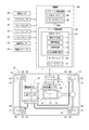
- FIG. 1 is a conceptual diagram illustrating a vehicle to which a brake control device according to an embodiment is applied.
- FIG. 2 is a perspective view of the shift range switching mechanism of FIG.
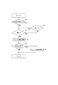
- FIG. 3 is a flowchart for explaining processing executed by the electronic control unit of the brake control device of FIG.
- FIG. 4 is a time chart showing an example of the operation by the processing of FIG.
- a brake control device which is a vehicle control device according to an embodiment, is used in a vehicle equipped with a shift-by-wire system (hereinafter, SBW system) and a brake-by-wire system (hereinafter, BBW system).
- SBW system shift-by-wire system
- BBW system brake-by-wire system
- the SBW system 11 of the vehicle 10 is a system that electrically controls the shift range switching mechanism 13 of the automatic transmission 12.
- the BBW system 15 is a system that electrically controls the hydraulic brake device 16.
- the SBW system 11 includes a shift actuator 21, a shift switch 22, a parking switch 23, a rotational position sensor 24, and a shift range control device 25.
- the shift actuator 21 is an electric actuator that outputs rotational power, and includes a motor 26, an encoder 27, a speed reducer 28, and an output shaft 29.
- the encoder 27 detects the rotational position of the motor 26.
- the speed reducer 28 decelerates the rotation of the motor 26.
- the output shaft 29 is connected to the shift range switching mechanism 13. When the output shaft 29 rotates, the shift range switching mechanism 13 operates, and the valve body position of the range switching valve 32 provided in the hydraulic circuit 31 of the automatic transmission 12 changes. The shift range of the automatic transmission 12 is switched according to the valve body position of the range switching valve 32.
- the shift range switching mechanism 13 has a detent plate 33 and a detent spring 34.
- the detent plate 33 rotates integrally with the output shaft 29 of the shift actuator 21.
- the valve body position of the range switching valve 32 is changed as the detent plate 33 rotates.
- the detent spring 34 holds the rotational position of the detent plate 33 by fitting into any one of the plurality of recesses 35 to 38 at the outer edge of the detent plate 33.
- the shift range switching mechanism 13 includes a parking gear 41, a parking pole 42, and a parking rod 43 as a mechanism for parking lock.
- the parking gear 41 rotates integrally with the output shaft of the automatic transmission 12.
- the parking pole 42 can move toward and away from the parking gear 41, and locks the rotation of the output shaft of the automatic transmission 12 by meshing with the parking gear 41.
- the parking rod 43 is connected to the detent plate 33, and when the rotation position of the detent plate 33 is a position corresponding to the parking range, the parking rod 43 is pushed by pushing the cone 48 at the tip portion below the parking pole 42.
- the pole 42 is pushed up so that the parking pole 42 and the parking gear 41 are engaged with each other.
- the cone 48 is repelled when the vehicle speed exceeds a predetermined speed.
- the shift switch 22 is operated by the driver of the vehicle 10, and outputs a signal corresponding to a shift range requested by the driver (hereinafter referred to as a requested shift range).
- the required shift range by the shift switch 22 includes, for example, a neutral range, a reverse range, and a drive range.
- the parking switch 23 is operated by the driver of the vehicle 10 and outputs a signal in response to a request for switching to the parking range by the driver.
- the rotational position sensor 24 detects the rotational position of the output shaft 29 and outputs a signal corresponding to the rotational position.
- the shift range control device 25 includes an electronic control unit (hereinafter referred to as SBW-ECU) 44 mainly composed of a microcomputer, and a motor driver 45 including an inverter that controls energization of the windings of the motor 26. .
- the SBW-ECU 44 outputs a command signal for driving the shift actuator 21 according to the output signals of the vehicle speed sensor 46, the brake sensor 47, the shift switch 22 and the parking switch 23.
- the motor driver 45 drives the shift actuator 21 in response to a command signal from the SBW-ECU 44.
- the shift range control device 25 controls the shift range by driving the shift actuator 21.
- the BBW system 15 includes an electric hydraulic pump 56, a hydraulic booster 57, a brake actuator 58, a brake device 16, a brake sensor 47, an inclination angle sensor 53, a disabling switch 54, and a brake control device 55.
- the hydraulic booster 57 increases the hydraulic pressure created by the electric hydraulic pump 56 and outputs it to the brake actuator 58.
- the brake actuator 58 has a plurality of solenoid valves (not shown), and supplies the hydraulic pressure adjusted by the solenoid valves to the brake device 16.
- the brake device 16 is a disc brake, and generates a braking force by sandwiching a brake rotor 62 that rotates together with the wheels 61 from both sides with a brake pad 64 using a brake caliper 63. This braking force changes according to the magnitude of the hydraulic pressure supplied from the brake actuator 58.
- the brake sensor 47 detects the speed and amount of depression of a brake pedal (not shown) by the driver of the vehicle 10 and outputs a signal corresponding to them.
- the tilt angle sensor 53 detects the tilt angle of the vehicle 10 and outputs a signal corresponding to the tilt angle.
- the inclination angle of the vehicle 10 corresponds to the slope of the road surface on which the vehicle 10 is located, and can be used to determine whether the vehicle 10 is located on a slope.
- the invalidation switch 54 is operated by the driver of the vehicle 10 and outputs a signal according to whether or not the driver has requested to invalidate the BBW automatic operation function.
- the “BBW automatic operation function” is a function for applying the brake by automatically operating the brake device 16 when a predetermined condition such as stopping is satisfied.
- the BBW automatic operation function is used, for example, to release the driver from the brake operation in waiting for a signal or the like.
- This BBW automatic operation function can be selectively disabled for a driver who avoids the acceleration delay when starting.
- This request for invalidation is the above-mentioned “BBW automatic activation function invalidation request”.
- the brake control device 55 includes an electronic control unit (hereinafter referred to as BBW-ECU) 65 mainly composed of a microcomputer, a motor driver 66 including an inverter that controls energization of the motor of the electric hydraulic pump 56, and a brake actuator 58. And a solenoid driver 67 for controlling energization of the solenoid.
- the BBW-ECU 65 outputs a command signal for driving the electric hydraulic pump 56 and the brake actuator 58 in accordance with output signals from the brake sensor 47, the tilt angle sensor 53, the invalidation switch 54, and the like.
- the motor driver 66 drives the electric hydraulic pump 56 in response to a command signal from the BBW-ECU 65.
- Solenoid driver 67 drives brake actuator 58 in response to a command signal from BBW-ECU 65.
- the brake control device 55 drives the electric hydraulic pump 56 and the brake actuator 58 to control the operation of the brake device 16.
- the brake control device 55 constitutes a control unit 68 of the vehicle 10 together with the shift range control device 25.
- the control unit 68 includes an engine control device and a parking brake control device that are not shown.
- the output signals of the various sensors acquired by the control unit 68 are shared among the control devices through a communication path such as CAN.
- BBW-ECU 65 ⁇ BBW-ECU>
- the brake device 16 is automatically operated by the BBW automatic operation function, so that the movement of the vehicle due to gravity is suppressed by the brake, so that the operation time of the shift range switching mechanism is relatively long. Even if it becomes, parking lock is considered possible. It is considered that the required torque of the shift actuator 21 for parking lock can be reduced. It is a completely new idea that the brake device 16 is automatically operated for such a purpose.
- the BBW-ECU 65 is an invalidation determination unit 71 that is a functional unit related to control for automatically operating the brake device 16 (hereinafter referred to as BBW automatic operation control).
- the vehicle has a stop determination unit 72, a slope determination unit 73, and a BBW automatic operation unit 74.
- the invalidation determination unit 71 determines whether there is a request for invalidating the BBW automatic operation function based on the output signal of the invalidation switch 54.
- the stop determination unit 72 determines whether or not the vehicle 10 has stopped based on the output signal of the vehicle speed sensor 46. For example, when the vehicle speed is 0, it is determined that the vehicle 10 has stopped.
- the slope determination unit 73 determines whether or not the vehicle 10 is located on the slope based on the output signal of the tilt angle sensor 53. When the inclination angle of the vehicle 10 is equal to or greater than a predetermined value, it is determined that the vehicle 10 is located on the slope, and when the inclination angle of the vehicle 10 is smaller than the predetermined value, the vehicle 10 is located on the slope. It is determined that it is not (located on a flat road).
- BBW automatic operation unit 74 exhibits the BBW automatic operation function when there is no invalidation request. “Exhibiting the BBW automatic operation function” refers to applying the brake by operating the brake device 16 when the vehicle stops.
- the BBW automatic operation unit 74 exhibits the BBW automatic operation function when the vehicle 10 is located on a slope.
- the BBW automatic operation unit 74 releases the brake by setting the brake device 16 to the release state when the shift range is the travel range (that is, the drive range or the reverse range) and the accelerator is on in the operation state of the brake device 16. To do.
- Each of the functional units 71 to 74 included in the BBW-ECU 65 may be realized by hardware processing using a dedicated logic circuit, or a program stored in advance in a memory such as a computer-readable non-transitory tangible recording medium is executed by the CPU. It may be realized by software processing by execution, or may be realized by a combination of both. Which part of each functional unit 71 to 74 is realized by hardware processing and which part is realized by software processing can be appropriately selected.
- the invalidation determination unit 71 determines whether there is a request for invalidating the BBW automatic operation function based on the output signal of the invalidation switch 54. If there is a request for invalidating the BBW automatic operation function (S1: YES), the process proceeds to S2. If there is no request for invalidating the BBW automatic operation function (S1: NO), the process proceeds to S3.
- the slope determination unit 73 determines whether or not the vehicle 10 is located on the slope based on the output signal of the tilt angle sensor 53. If the vehicle 10 is located on a slope (S2: YES), the process proceeds to S3. When the vehicle 10 is not located on the slope (S2: NO), the process proceeds to S6.
- the stop determination unit 72 determines whether or not the vehicle 10 has stopped based on the output signal of the vehicle speed sensor 46.
- the process proceeds to S4.
- the process proceeds to S6.
- the BBW automatic operation unit 74 operates the brake device 16 to apply the brake. After S4, the process proceeds to S5.
- the BBW automatic operation unit 74 determines whether or not the shift range is the travel range and the accelerator is on. If the shift range is the travel range and the accelerator is on (S5: YES), the process proceeds to S6. If the shift range is not the travel range or if the accelerator is off (S5: NO), the process exits the routine of FIG.
- the invalidation switch 54 is turned on (that is, there is an invalidation request), and the inclination angle is 0 (that is, the vehicle 10 is not located on the slope), so that the brake device 16 is in the released state. It becomes.
- the determination of S1 in FIG. 3 is affirmed and the determination of S2 is denied, and the process of S6 is executed.
- the shift range control device 25 drives the shift actuator 21 to switch the shift range from the drive range to the parking range. While the drive range is switched to the parking range, the brake device 16 is in an operating state, and the movement of the vehicle due to gravity is suppressed. Therefore, the parking lock can be performed even if the operation time of the shift range switching mechanism 13 after time t5 is relatively long.
- the shift range control device 25 drives the shift actuator 21 to switch the shift range from the parking range to the drive range.
- the movement of the vehicle due to gravity is suppressed by the brake device 16.
- the force that the vehicle tries to move due to gravity is less likely to be applied to the meshing portion between the parking gear 41 and the parking pole 42. Therefore, the shift actuator 21 can easily remove the parking pole 42 from the parking gear 41 at time t6. That is, an increase in motor torque necessary for releasing the meshing is suppressed.
- the brake control device 55 includes the invalidation determination unit 71, the stop determination unit 72, the slope determination unit 73, and the BBW automatic operation unit 74.
- the invalidation determination unit 71 determines whether there is an invalidation request.
- the stop determination unit 72 determines whether or not the vehicle 10 is stopped.
- the slope determination unit 73 determines whether or not the vehicle 10 is located on the slope.
- the BBW automatic operation unit 74 operates the brake device 16 by the BBW automatic operation function when the vehicle 10 is located on a slope and the vehicle 10 is stopped even when there is a request for invalidation. .
- the brake device 16 is automatically operated regardless of the invalidation request, so that the movement of the vehicle 10 due to gravity is suppressed by the brake device 16. Therefore, parking lock is possible even if the operation time of the shift range switching mechanism 13 of the shift-by-wire system 11 is relatively long. Therefore, since the torque of the shift actuator 21 required at the time of parking lock is reduced, the shift actuator 21 can be reduced in size.
- conditions other than stopping the vehicle may be included in the conditions for setting the brake device in the operating state by the BBW automatic operation function.
- the brake device may be a brake operated by a mechanical force instead of a brake operated by hydraulic pressure. That is, the brake actuator is not a hydraulic device that supplies hydraulic pressure to the brake device, but may be composed of, for example, an electric motor and output a mechanical force to the brake device. That is, the brake-by-wire system may include an electric brake and a brake control device that controls the electric brake.
- the brake device is not limited to the disk type, but may be of another type such as a drum type.
- the brake device is not limited to all the wheels of the vehicle, but may be provided only on the front wheels or the rear wheels, or may be provided on a drive shaft or the like other than the wheels.
Abstract
The present invention provides a brake control device (55) that is a vehicle control device used in a vehicle (10) in which a shift-by-wire system (11) and a brake-by-wire system (15) are installed. A BBW automatic actuation function is a function for automatically actuating a brake device (16) without manipulation by the driver of the vehicle (10), and a disable request is a request by the driver to disable the BBW automatic actuation function. The brake control device (55) is equipped with a disablement determination unit (71) for determining whether or not there is a disable request, a stopped vehicle determination unit (72) for determining whether or not the vehicle (10) is stopped, a sloping road determination unit (73) for determining whether or not the vehicle is positioned upon a sloping road, and a BBW automatic actuation unit (74). Even in cases in which there is a disable request, the BBW automatic actuation unit (74) actuates the brake device (16) when the vehicle (10) is stopped upon a sloping road.
Description
本出願は、2017年3月29日に出願された特許出願番号2017-65386号に基づくものであり、ここにその記載内容を援用する。
This application is based on patent application No. 2017-65386 filed on Mar. 29, 2017, the contents of which are incorporated herein by reference.
本開示は、車両用制御装置に関する。
This disclosure relates to a vehicle control device.
モータ等を駆動源としたシフトアクチュエータにより車両のシフトレンジ切替機構を作動させるシフトバイワイヤシステムが知られている。このシステムでは、シフトレンジ切替機構とその操作部とを機械的に接続する必要がない。そのため、操作部の設置場所およびデザインの自由度が増す。
A shift-by-wire system is known in which a shift range switching mechanism of a vehicle is operated by a shift actuator using a motor or the like as a drive source. In this system, there is no need to mechanically connect the shift range switching mechanism and its operation unit. Therefore, the installation location of the operation unit and the degree of freedom in design increase.
ところで、現状のシフトレンジ切替機構では、車速が所定速度以上になるとパーキングロックできないようにラチェット機構が設けられている。そのため、坂道では、シフトアクチュエータを速く作動させないと、車両がずり下がって車速が上がりパーキングロックできなくなる。
これに対して、特許文献1に開示されたシフトレンジ切替機構では、パーキングロックにかかる時間を短縮するためにディテントプレートの形状を工夫している。 By the way, in the current shift range switching mechanism, a ratchet mechanism is provided so that parking lock cannot be performed when the vehicle speed exceeds a predetermined speed. Therefore, on a slope, unless the shift actuator is actuated quickly, the vehicle slides down, the vehicle speed increases, and parking lock cannot be performed.
On the other hand, in the shift range switching mechanism disclosed in Patent Document 1, the shape of the detent plate is devised in order to shorten the time required for parking lock.
ところで近年、車両搭載性の向上等のためにシフトアクチュエータの小型化の要請がある。しかし、シフトアクチュエータを小型化すれば、出力トルクが低下してシフトレンジ切替機構の作動に時間がかかるようになる。そのため、パーキングロック完了までに時間を要する結果、坂道でのパーキングロックが難しくなるおそれがある。
Incidentally, in recent years, there is a demand for downsizing of the shift actuator in order to improve vehicle mountability. However, if the shift actuator is reduced in size, the output torque decreases, and the operation of the shift range switching mechanism takes time. Therefore, as a result of the time required for completing the parking lock, it may be difficult to perform the parking lock on the slope.
パーキングロックの時間短縮については、特許文献1におけるディテントプレートの形状工夫が有効であるとも考えられる。しかし、ディテントプレートの形状工夫によるパーキングロックの時間短縮には限界があり、シフトアクチュエータの小型化のための更なる改良が望まれている。
本開示の目的は、シフトバイワイヤシステムのシフトアクチュエータを小型化することができる車両用制御装置を提供することである。 Regarding the shortening of the parking lock time, it is considered that the detent plate shape device in Patent Document 1 is effective. However, there is a limit to shortening the time for parking lock by devising the shape of the detent plate, and further improvements for downsizing the shift actuator are desired.
The objective of this indication is providing the control apparatus for vehicles which can reduce the size of the shift actuator of a shift-by-wire system.
従来、ブレーキバイワイヤシステムを搭載した車両において、例えば停車する等の所定の条件が揃ったときにブレーキバイワイヤシステムのブレーキ装置を自動的に作動させる機能(以下、BBW自動作動機能)がある。BBW自動作動機能は、例えば信号待ち等においてブレーキ操作からドライバーを開放するために用いられる。BBW自動作動機能によるブレーキ装置の作動状態は、例えばアクセルオンにより解除される。
Conventionally, a vehicle equipped with a brake-by-wire system has a function of automatically operating a brake device of the brake-by-wire system (hereinafter referred to as a BBW automatic operation function) when a predetermined condition such as stopping is met. The BBW automatic operation function is used, for example, to release the driver from the brake operation in waiting for a signal or the like. The operation state of the brake device by the BBW automatic operation function is canceled by, for example, turning on the accelerator.
本開示者は、坂道で停車したときにブレーキ装置を自動的に作動させることで、重力による車両の移動がブレーキで抑制されるため、シフトレンジ切替機構の作動時間が比較的長くなってもパーキングロック可能であると考えた。そして、パーキングロックのためのシフトアクチュエータの要求トルクを低減することができると考えた。このような目的のためにブレーキ装置を自動的に作動させることは、従来にない全く新しい発想である。
The present disclosure allows the brake device to automatically operate when the vehicle stops on a hill, so that the movement of the vehicle due to gravity is suppressed by the brake. Therefore, even if the operation time of the shift range switching mechanism becomes relatively long, parking is performed. I thought it was lockable. Then, it was considered that the required torque of the shift actuator for parking lock can be reduced. It is a completely new idea that the brake device is automatically operated for such a purpose.
しかし、現状のブレーキバイワイヤシステムにおいて、BBW自動作動機能は、発進時の加速遅れを敬遠するドライバーのために選択的に無効化することができるようになっている。このようにBBW自動作動機能を無効化したときには、坂道で停車したときにブレーキ装置が作動しないため、パーキングロックのためのシフトアクチュエータの要求トルクを低減することができないという新たな問題が生じる。
本開示者は、この知見に基づき本開示を完成するに至った。 However, in the current brake-by-wire system, the BBW automatic operation function can be selectively disabled for a driver who avoids the acceleration delay when starting. As described above, when the BBW automatic operation function is invalidated, the brake device does not operate when the vehicle stops on a slope, so that a new problem arises that the required torque of the shift actuator for parking lock cannot be reduced.
Based on this finding, the present inventors have completed the present disclosure.
本開示は、シフトバイワイヤシステムおよびブレーキバイワイヤシステムを搭載した車両に用いられる車両用制御装置である。
ここで、車両のドライバーの操作なしにブレーキバイワイヤシステムのブレーキ装置を自動的に作動させる機能をBBW自動作動機能とし、当該BBW自動作動機能を無効化するためのドライバーによる要求を無効化要求とする。 The present disclosure is a vehicle control device used in a vehicle equipped with a shift-by-wire system and a brake-by-wire system.
Here, the function of automatically operating the brake device of the brake-by-wire system without the operation of the driver of the vehicle is a BBW automatic operation function, and the request by the driver for invalidating the BBW automatic operation function is the invalidation request. .
車両用制御装置は、無効化判定部、停車判定部、坂道判定部およびBBW自動作動部を備えている。
無効化判定部は、無効化要求の有無を判定する。
停車判定部は、車両が停車しているか否かを判定する。
坂道判定部は、車両が坂道の上に位置しているか否かを判定する。
BBW自動作動部は、無効化要求が有る場合であっても、車両が坂道の上に位置しておりかつ車両が停車しているときには、BBW自動作動機能によりブレーキ装置を作動させる。 The vehicle control device includes an invalidation determination unit, a stop determination unit, a slope determination unit, and a BBW automatic operation unit.
The invalidation determination unit determines whether there is an invalidation request.
The stop determination unit determines whether or not the vehicle is stopped.
The slope determination unit determines whether or not the vehicle is located on the slope.
The BBW automatic operation unit operates the brake device by the BBW automatic operation function when the vehicle is located on the slope and the vehicle is stopped even when there is a request for invalidation.
このように車両が坂道の上で停車した場合、無効化要求にかかわらずブレーキ装置を自動的に作動させることで、重力による車両の移動がブレーキにより抑制される。そのため、シフトバイワイヤシステムのシフトレンジ切替機構の作動時間が比較的長くてもパーキングロックが可能となる。したがって、パーキングロック時に要求されるシフトアクチュエータのトルクが低減するので、シフトアクチュエータを小型化することができる。
When the vehicle stops on the slope in this way, the brake device is automatically operated regardless of the invalidation request, so that the movement of the vehicle due to gravity is suppressed by the brake. Therefore, parking lock is possible even if the operation time of the shift range switching mechanism of the shift-by-wire system is relatively long. Therefore, since the torque of the shift actuator required at the time of parking lock is reduced, the shift actuator can be reduced in size.
本開示についての上記目的およびその他の目的、特徴や利点は、添付の図面を参照しながら下記の詳細な記述により、より明確になる。その図面は、
図1は、一実施形態のブレーキ制御装置が適用された車両について説明する概念図であり、
図2は、図1のシフトレンジ切替機構の斜視図であり、
図3は、図1のブレーキ制御装置の電子制御ユニットが実行する処理を説明するフローチャートであり、
図4は、図3の処理による動作の一例を示すタイムチャートである。
The above and other objects, features and advantages of the present disclosure will become more apparent from the following detailed description with reference to the accompanying drawings. The drawing
FIG. 1 is a conceptual diagram illustrating a vehicle to which a brake control device according to an embodiment is applied. FIG. 2 is a perspective view of the shift range switching mechanism of FIG. FIG. 3 is a flowchart for explaining processing executed by the electronic control unit of the brake control device of FIG. FIG. 4 is a time chart showing an example of the operation by the processing of FIG.
以下、一実施形態を図面に基づき説明する。
[一実施形態]
一実施形態の車両用制御装置であるブレーキ制御装置は、シフトバイワイヤシステム(以下、SBWシステム)およびブレーキバイワイヤシステム(以下、BBWシステム)を搭載した車両に用いられる。図1に示すように、車両10のSBWシステム11は、自動変速機12のシフトレンジ切替機構13を電気的に制御するシステムである。BBWシステム15は、油圧式のブレーキ装置16を電気的に制御するシステムである。 Hereinafter, an embodiment will be described with reference to the drawings.
[One Embodiment]
A brake control device, which is a vehicle control device according to an embodiment, is used in a vehicle equipped with a shift-by-wire system (hereinafter, SBW system) and a brake-by-wire system (hereinafter, BBW system). As shown in FIG. 1, the SBWsystem 11 of the vehicle 10 is a system that electrically controls the shift range switching mechanism 13 of the automatic transmission 12. The BBW system 15 is a system that electrically controls the hydraulic brake device 16.
[一実施形態]
一実施形態の車両用制御装置であるブレーキ制御装置は、シフトバイワイヤシステム(以下、SBWシステム)およびブレーキバイワイヤシステム(以下、BBWシステム)を搭載した車両に用いられる。図1に示すように、車両10のSBWシステム11は、自動変速機12のシフトレンジ切替機構13を電気的に制御するシステムである。BBWシステム15は、油圧式のブレーキ装置16を電気的に制御するシステムである。 Hereinafter, an embodiment will be described with reference to the drawings.
[One Embodiment]
A brake control device, which is a vehicle control device according to an embodiment, is used in a vehicle equipped with a shift-by-wire system (hereinafter, SBW system) and a brake-by-wire system (hereinafter, BBW system). As shown in FIG. 1, the SBW
<SBWシステム>
先ず、SBWシステム11の構成について図1、図2を参照して説明する。
図1に示すように、SBWシステム11は、シフトアクチュエータ21、シフトスイッチ22、パーキングスイッチ23、回転位置センサ24およびシフトレンジ制御装置25を備えている。 <SBW system>
First, the configuration of the SBWsystem 11 will be described with reference to FIGS.
As shown in FIG. 1, the SBWsystem 11 includes a shift actuator 21, a shift switch 22, a parking switch 23, a rotational position sensor 24, and a shift range control device 25.
先ず、SBWシステム11の構成について図1、図2を参照して説明する。
図1に示すように、SBWシステム11は、シフトアクチュエータ21、シフトスイッチ22、パーキングスイッチ23、回転位置センサ24およびシフトレンジ制御装置25を備えている。 <SBW system>
First, the configuration of the SBW
As shown in FIG. 1, the SBW
シフトアクチュエータ21は、回転動力を出力する電動アクチュエータであり、モータ26、エンコーダ27、減速機28および出力軸29を有している。エンコーダ27は、モータ26の回転位置を検出する。減速機28は、モータ26の回転を減速する。出力軸29は、シフトレンジ切替機構13に接続されている。出力軸29が回転するとシフトレンジ切替機構13が作動し、自動変速機12の油圧回路31に設けられたレンジ切替弁32の弁体位置が変わる。自動変速機12のシフトレンジは、レンジ切替弁32の弁体位置に応じて切り替わる。
The shift actuator 21 is an electric actuator that outputs rotational power, and includes a motor 26, an encoder 27, a speed reducer 28, and an output shaft 29. The encoder 27 detects the rotational position of the motor 26. The speed reducer 28 decelerates the rotation of the motor 26. The output shaft 29 is connected to the shift range switching mechanism 13. When the output shaft 29 rotates, the shift range switching mechanism 13 operates, and the valve body position of the range switching valve 32 provided in the hydraulic circuit 31 of the automatic transmission 12 changes. The shift range of the automatic transmission 12 is switched according to the valve body position of the range switching valve 32.
図2に示すように、シフトレンジ切替機構13(図1参照)は、ディテントプレート33およびディテントスプリング34を有している。ディテントプレート33は、シフトアクチュエータ21の出力軸29と一体に回転する。レンジ切替弁32の弁体位置は、ディテントプレート33の回転に伴い変更される。ディテントスプリング34は、ディテントプレート33の外縁部にある複数の凹部35~38のうち、いずれか1つに嵌まることでディテントプレート33の回転位置を保持する。
As shown in FIG. 2, the shift range switching mechanism 13 (see FIG. 1) has a detent plate 33 and a detent spring 34. The detent plate 33 rotates integrally with the output shaft 29 of the shift actuator 21. The valve body position of the range switching valve 32 is changed as the detent plate 33 rotates. The detent spring 34 holds the rotational position of the detent plate 33 by fitting into any one of the plurality of recesses 35 to 38 at the outer edge of the detent plate 33.
また、シフトレンジ切替機構13は、パーキングロックのための機構を構成するものとして、パーキングギヤ41、パーキングポール42およびパーキングロッド43を有している。パーキングギヤ41は、自動変速機12のアウトプットシャフトと一体に回転する。パーキングポール42は、パーキングギヤ41に対して接近および離間可能であり、パーキングギヤ41と噛み合うことで自動変速機12のアウトプットシャフトの回転をロックする。パーキングロッド43は、ディテントプレート33に連結されており、ディテントプレート33の回転位置がパーキングレンジに対応する位置であるとき、先端部の円錐体48をパーキングポール42の下側に押し込むことで当該パーキングポール42を押し上げて、パーキングポール42とパーキングギヤ41とを噛み合わせる。円錐体48は、車速が所定速度以上になるとはじかれるようになっている。
The shift range switching mechanism 13 includes a parking gear 41, a parking pole 42, and a parking rod 43 as a mechanism for parking lock. The parking gear 41 rotates integrally with the output shaft of the automatic transmission 12. The parking pole 42 can move toward and away from the parking gear 41, and locks the rotation of the output shaft of the automatic transmission 12 by meshing with the parking gear 41. The parking rod 43 is connected to the detent plate 33, and when the rotation position of the detent plate 33 is a position corresponding to the parking range, the parking rod 43 is pushed by pushing the cone 48 at the tip portion below the parking pole 42. The pole 42 is pushed up so that the parking pole 42 and the parking gear 41 are engaged with each other. The cone 48 is repelled when the vehicle speed exceeds a predetermined speed.
図1に戻って、シフトスイッチ22は、車両10のドライバーにより操作されるものであり、ドライバーの要求するシフトレンジ(以下、要求シフトレンジ)に応じた信号を出力する。シフトスイッチ22による要求シフトレンジには、例えばニュートラルレンジ、リバースレンジおよびドライブレンジなどがある。
パーキングスイッチ23は、車両10のドライバーにより操作されるものであり、ドライバーによるパーキングレンジへの切り替え要求に応じた信号を出力する。
回転位置センサ24は、出力軸29の回転位置を検出して、当該回転位置に応じた信号を出力する。 Returning to FIG. 1, theshift switch 22 is operated by the driver of the vehicle 10, and outputs a signal corresponding to a shift range requested by the driver (hereinafter referred to as a requested shift range). The required shift range by the shift switch 22 includes, for example, a neutral range, a reverse range, and a drive range.
Theparking switch 23 is operated by the driver of the vehicle 10 and outputs a signal in response to a request for switching to the parking range by the driver.
Therotational position sensor 24 detects the rotational position of the output shaft 29 and outputs a signal corresponding to the rotational position.
パーキングスイッチ23は、車両10のドライバーにより操作されるものであり、ドライバーによるパーキングレンジへの切り替え要求に応じた信号を出力する。
回転位置センサ24は、出力軸29の回転位置を検出して、当該回転位置に応じた信号を出力する。 Returning to FIG. 1, the
The
The
シフトレンジ制御装置25は、マイクロコンピュータを主体として構成されている電子制御ユニット(以下、SBW-ECU)44と、モータ26の巻線の通電を制御するインバータを含むモータドライバ45とを備えている。SBW-ECU44は、車速センサ46、ブレーキセンサ47、シフトスイッチ22およびパーキングスイッチ23の出力信号に応じて、シフトアクチュエータ21を駆動するための指令信号を出力する。モータドライバ45は、SBW-ECU44からの指令信号に応じてシフトアクチュエータ21を駆動する。シフトレンジ制御装置25は、シフトアクチュエータ21を駆動してシフトレンジを制御する。
The shift range control device 25 includes an electronic control unit (hereinafter referred to as SBW-ECU) 44 mainly composed of a microcomputer, and a motor driver 45 including an inverter that controls energization of the windings of the motor 26. . The SBW-ECU 44 outputs a command signal for driving the shift actuator 21 according to the output signals of the vehicle speed sensor 46, the brake sensor 47, the shift switch 22 and the parking switch 23. The motor driver 45 drives the shift actuator 21 in response to a command signal from the SBW-ECU 44. The shift range control device 25 controls the shift range by driving the shift actuator 21.
<BBWシステム>
次に、BBWシステム15の構成について図1を参照して説明する。
BBWシステム15は、電動油圧ポンプ56、油圧ブースタ57、ブレーキアクチュエータ58、ブレーキ装置16、ブレーキセンサ47、傾斜角センサ53、無効化スイッチ54およびブレーキ制御装置55を備えている。 <BBW system>
Next, the configuration of theBBW system 15 will be described with reference to FIG.
TheBBW system 15 includes an electric hydraulic pump 56, a hydraulic booster 57, a brake actuator 58, a brake device 16, a brake sensor 47, an inclination angle sensor 53, a disabling switch 54, and a brake control device 55.
次に、BBWシステム15の構成について図1を参照して説明する。
BBWシステム15は、電動油圧ポンプ56、油圧ブースタ57、ブレーキアクチュエータ58、ブレーキ装置16、ブレーキセンサ47、傾斜角センサ53、無効化スイッチ54およびブレーキ制御装置55を備えている。 <BBW system>
Next, the configuration of the
The
油圧ブースタ57は、電動油圧ポンプ56が作り出した油圧を増圧してブレーキアクチュエータ58に出力する。
ブレーキアクチュエータ58は、図示しない複数のソレノイドバルブを有しており、当該ソレノイドバルブにより調圧された油圧をブレーキ装置16へ供給する。
ブレーキ装置16は、ディスクブレーキであり、車輪61と共に回転するブレーキロータ62を、ブレーキキャリパ63を用いてブレーキパッド64で両側から挟み込むことによって制動力を発生させる。この制動力は、ブレーキアクチュエータ58から供給される油圧の大きさに応じて変化する。 Thehydraulic booster 57 increases the hydraulic pressure created by the electric hydraulic pump 56 and outputs it to the brake actuator 58.
Thebrake actuator 58 has a plurality of solenoid valves (not shown), and supplies the hydraulic pressure adjusted by the solenoid valves to the brake device 16.
Thebrake device 16 is a disc brake, and generates a braking force by sandwiching a brake rotor 62 that rotates together with the wheels 61 from both sides with a brake pad 64 using a brake caliper 63. This braking force changes according to the magnitude of the hydraulic pressure supplied from the brake actuator 58.
ブレーキアクチュエータ58は、図示しない複数のソレノイドバルブを有しており、当該ソレノイドバルブにより調圧された油圧をブレーキ装置16へ供給する。
ブレーキ装置16は、ディスクブレーキであり、車輪61と共に回転するブレーキロータ62を、ブレーキキャリパ63を用いてブレーキパッド64で両側から挟み込むことによって制動力を発生させる。この制動力は、ブレーキアクチュエータ58から供給される油圧の大きさに応じて変化する。 The
The
The
ブレーキセンサ47は、車両10のドライバーが図示しないブレーキペダルを踏む速度および踏み込み量を検出し、それらに応じた信号を出力する。
傾斜角センサ53は、車両10の傾斜角を検出して、当該傾斜角に応じた信号を出力する。車両10の傾斜角は、車両10が位置している路面の勾配に対応しており、車両10が坂道の上に位置しているか否かの判断に利用可能である。
無効化スイッチ54は、車両10のドライバーにより操作されるものであり、ドライバーによるBBW自動作動機能の無効化要求の有無に応じた信号を出力する。 Thebrake sensor 47 detects the speed and amount of depression of a brake pedal (not shown) by the driver of the vehicle 10 and outputs a signal corresponding to them.
Thetilt angle sensor 53 detects the tilt angle of the vehicle 10 and outputs a signal corresponding to the tilt angle. The inclination angle of the vehicle 10 corresponds to the slope of the road surface on which the vehicle 10 is located, and can be used to determine whether the vehicle 10 is located on a slope.
Theinvalidation switch 54 is operated by the driver of the vehicle 10 and outputs a signal according to whether or not the driver has requested to invalidate the BBW automatic operation function.
傾斜角センサ53は、車両10の傾斜角を検出して、当該傾斜角に応じた信号を出力する。車両10の傾斜角は、車両10が位置している路面の勾配に対応しており、車両10が坂道の上に位置しているか否かの判断に利用可能である。
無効化スイッチ54は、車両10のドライバーにより操作されるものであり、ドライバーによるBBW自動作動機能の無効化要求の有無に応じた信号を出力する。 The
The
The
ここで、「BBW自動作動機能」とは、例えば停車する等の所定の条件が揃ったときにブレーキ装置16を自動的に作動させてブレーキをかける機能である。BBW自動作動機能は、例えば信号待ち等においてブレーキ操作からドライバーを開放するために用いられる。このBBW自動作動機能は、発進時の加速遅れを敬遠するドライバーのために選択的に無効化することができるようになっている。この無効化のための要求が、上述の「BBW自動作動機能の無効化要求」である。
Here, the “BBW automatic operation function” is a function for applying the brake by automatically operating the brake device 16 when a predetermined condition such as stopping is satisfied. The BBW automatic operation function is used, for example, to release the driver from the brake operation in waiting for a signal or the like. This BBW automatic operation function can be selectively disabled for a driver who avoids the acceleration delay when starting. This request for invalidation is the above-mentioned “BBW automatic activation function invalidation request”.
ブレーキ制御装置55は、マイクロコンピュータを主体として構成されている電子制御ユニット(以下、BBW-ECU)65と、電動油圧ポンプ56のモータの通電を制御するインバータを含むモータドライバ66と、ブレーキアクチュエータ58のソレノイドの通電を制御するソレノイドドライバ67とを備えている。BBW-ECU65は、ブレーキセンサ47、傾斜角センサ53および無効化スイッチ54等の出力信号に応じて、電動油圧ポンプ56およびブレーキアクチュエータ58を駆動するための指令信号を出力する。モータドライバ66は、BBW-ECU65からの指令信号に応じて電動油圧ポンプ56を駆動する。ソレノイドドライバ67は、BBW-ECU65からの指令信号に応じてブレーキアクチュエータ58を駆動する。ブレーキ制御装置55は、電動油圧ポンプ56およびブレーキアクチュエータ58を駆動してブレーキ装置16の作動を制御する。
The brake control device 55 includes an electronic control unit (hereinafter referred to as BBW-ECU) 65 mainly composed of a microcomputer, a motor driver 66 including an inverter that controls energization of the motor of the electric hydraulic pump 56, and a brake actuator 58. And a solenoid driver 67 for controlling energization of the solenoid. The BBW-ECU 65 outputs a command signal for driving the electric hydraulic pump 56 and the brake actuator 58 in accordance with output signals from the brake sensor 47, the tilt angle sensor 53, the invalidation switch 54, and the like. The motor driver 66 drives the electric hydraulic pump 56 in response to a command signal from the BBW-ECU 65. Solenoid driver 67 drives brake actuator 58 in response to a command signal from BBW-ECU 65. The brake control device 55 drives the electric hydraulic pump 56 and the brake actuator 58 to control the operation of the brake device 16.
ブレーキ制御装置55は、シフトレンジ制御装置25とともに車両10の制御部68を構成している。制御部68は、他にも図示しないエンジン制御装置およびパーキングブレーキ制御装置などを有している。制御部68が取得した各種センサの出力信号は、例えばCAN等の通信路を通じて各制御装置間で共有される。
The brake control device 55 constitutes a control unit 68 of the vehicle 10 together with the shift range control device 25. The control unit 68 includes an engine control device and a parking brake control device that are not shown. The output signals of the various sensors acquired by the control unit 68 are shared among the control devices through a communication path such as CAN.
<BBW-ECU>
次に、BBW-ECU65の詳細な構成について図1を参照して説明する。
ここで、坂道で停車したときにBBW自動作動機能によりブレーキ装置16を自動的に作動させることで、重力による車両の移動がブレーキで抑制されるため、シフトレンジ切替機構の作動時間が比較的長くなってもパーキングロック可能であると考えられる。そして、パーキングロックのためのシフトアクチュエータ21の要求トルクを低減することができると考えられる。このような目的のためにブレーキ装置16を自動的に作動させることは、従来にない全く新しい発想である。 <BBW-ECU>
Next, the detailed configuration of the BBW-ECU 65 will be described with reference to FIG.
Here, when the vehicle stops on a slope, thebrake device 16 is automatically operated by the BBW automatic operation function, so that the movement of the vehicle due to gravity is suppressed by the brake, so that the operation time of the shift range switching mechanism is relatively long. Even if it becomes, parking lock is considered possible. It is considered that the required torque of the shift actuator 21 for parking lock can be reduced. It is a completely new idea that the brake device 16 is automatically operated for such a purpose.
次に、BBW-ECU65の詳細な構成について図1を参照して説明する。
ここで、坂道で停車したときにBBW自動作動機能によりブレーキ装置16を自動的に作動させることで、重力による車両の移動がブレーキで抑制されるため、シフトレンジ切替機構の作動時間が比較的長くなってもパーキングロック可能であると考えられる。そして、パーキングロックのためのシフトアクチュエータ21の要求トルクを低減することができると考えられる。このような目的のためにブレーキ装置16を自動的に作動させることは、従来にない全く新しい発想である。 <BBW-ECU>
Next, the detailed configuration of the BBW-
Here, when the vehicle stops on a slope, the
しかし、従来のシステムと同じように、無効化スイッチ54によりBBW自動作動機能が無効化されているとき坂道で停車した際にブレーキ装置16が作動しないように構成されている場合、パーキングロックのためのシフトアクチュエータ21の要求トルクを低減することができないという新たな問題が生じる。
However, as in the case of the conventional system, when the brake device 16 is configured not to operate when stopping on a slope when the BBW automatic operation function is disabled by the disabling switch 54, the parking lock is used. There arises a new problem that the required torque of the shift actuator 21 cannot be reduced.
このような問題を解消する構成として、図1に示すように、BBW-ECU65は、ブレーキ装置16を自動的に作動させる制御(以下、BBW自動作動制御)に関する機能部である無効化判定部71、停車判定部72、坂道判定部73およびBBW自動作動部74を有している。
As a configuration for solving such a problem, as shown in FIG. 1, the BBW-ECU 65 is an invalidation determination unit 71 that is a functional unit related to control for automatically operating the brake device 16 (hereinafter referred to as BBW automatic operation control). The vehicle has a stop determination unit 72, a slope determination unit 73, and a BBW automatic operation unit 74.
無効化判定部71は、無効化スイッチ54の出力信号に基づき、BBW自動作動機能の無効化要求の有無を判定する。
停車判定部72は、車速センサ46の出力信号に基づき、車両10が停止したか否かを判定する。例えば車速が0である場合に車両10が停止したと判定される。 Theinvalidation determination unit 71 determines whether there is a request for invalidating the BBW automatic operation function based on the output signal of the invalidation switch 54.
Thestop determination unit 72 determines whether or not the vehicle 10 has stopped based on the output signal of the vehicle speed sensor 46. For example, when the vehicle speed is 0, it is determined that the vehicle 10 has stopped.
停車判定部72は、車速センサ46の出力信号に基づき、車両10が停止したか否かを判定する。例えば車速が0である場合に車両10が停止したと判定される。 The
The
坂道判定部73は、傾斜角センサ53の出力信号に基づき、車両10が坂道の上に位置しているか否かを判定する。車両10の傾斜角が所定値以上である場合に車両10が坂道の上に位置していると判定され、また、車両10の傾斜角が所定値より小さい場合に車両10が坂道の上に位置していない(平坦路の上に位置している)と判定される。
The slope determination unit 73 determines whether or not the vehicle 10 is located on the slope based on the output signal of the tilt angle sensor 53. When the inclination angle of the vehicle 10 is equal to or greater than a predetermined value, it is determined that the vehicle 10 is located on the slope, and when the inclination angle of the vehicle 10 is smaller than the predetermined value, the vehicle 10 is located on the slope. It is determined that it is not (located on a flat road).
BBW自動作動部74は、無効化要求が無い場合、BBW自動作動機能を発揮させる。「BBW自動作動機能を発揮させる」とは、本実施形態では停車したときにブレーキ装置16を作動させてブレーキをかけることをいう。
BBW automatic operation unit 74 exhibits the BBW automatic operation function when there is no invalidation request. “Exhibiting the BBW automatic operation function” refers to applying the brake by operating the brake device 16 when the vehicle stops.
また、BBW自動作動部74は、無効化要求が有る場合であっても、車両10が坂道の上に位置しているときにはBBW自動作動機能を発揮させる。
また、BBW自動作動部74は、ブレーキ装置16の作動状態において、シフトレンジが走行レンジ(すなわち、ドライブレンジまたはリバースレンジ)であり且つアクセルオンである場合、ブレーキ装置16を解除状態としてブレーキを解除する。 Further, even when there is a request for invalidation, the BBWautomatic operation unit 74 exhibits the BBW automatic operation function when the vehicle 10 is located on a slope.
In addition, the BBWautomatic operation unit 74 releases the brake by setting the brake device 16 to the release state when the shift range is the travel range (that is, the drive range or the reverse range) and the accelerator is on in the operation state of the brake device 16. To do.
また、BBW自動作動部74は、ブレーキ装置16の作動状態において、シフトレンジが走行レンジ(すなわち、ドライブレンジまたはリバースレンジ)であり且つアクセルオンである場合、ブレーキ装置16を解除状態としてブレーキを解除する。 Further, even when there is a request for invalidation, the BBW
In addition, the BBW
BBW-ECU65が有する各機能部71~74は、専用の論理回路によるハードウェア処理により実現されてもよいし、コンピュータ読み出し可能非一時的有形記録媒体等のメモリに予め記憶されたプログラムをCPUで実行することによるソフトウェア処理により実現されてもよいし、あるいは、両者の組み合わせで実現されてもよい。各機能部71~74のうちどの部分をハードウェア処理により実現し、どの部分をソフトウェア処理により実現するかは、適宜選択可能である。
Each of the functional units 71 to 74 included in the BBW-ECU 65 may be realized by hardware processing using a dedicated logic circuit, or a program stored in advance in a memory such as a computer-readable non-transitory tangible recording medium is executed by the CPU. It may be realized by software processing by execution, or may be realized by a combination of both. Which part of each functional unit 71 to 74 is realized by hardware processing and which part is realized by software processing can be appropriately selected.
<BBW-ECUが実行する処理>
次に、BBW-ECU65がBBW自動作動制御のために実行する一連の処理について図1および図3を参照して説明する。図3に示すルーチンは、BBW-ECU65の起動後に繰り返し実行される。以降、「S」はステップを意味する。 <Processing executed by BBW-ECU>
Next, a series of processing executed by the BBW-ECU 65 for BBW automatic operation control will be described with reference to FIGS. The routine shown in FIG. 3 is repeatedly executed after the BBW-ECU 65 is started. Hereinafter, “S” means a step.
次に、BBW-ECU65がBBW自動作動制御のために実行する一連の処理について図1および図3を参照して説明する。図3に示すルーチンは、BBW-ECU65の起動後に繰り返し実行される。以降、「S」はステップを意味する。 <Processing executed by BBW-ECU>
Next, a series of processing executed by the BBW-
図3のS1において、無効化判定部71は、無効化スイッチ54の出力信号に基づき、BBW自動作動機能の無効化要求が有るか否かを判定する。
BBW自動作動機能の無効化要求が有る場合(S1:YES)、処理はS2に移行する。
BBW自動作動機能の無効化要求が無い場合(S1:NO)、処理はS3に移行する。 In S <b> 1 of FIG. 3, theinvalidation determination unit 71 determines whether there is a request for invalidating the BBW automatic operation function based on the output signal of the invalidation switch 54.
If there is a request for invalidating the BBW automatic operation function (S1: YES), the process proceeds to S2.
If there is no request for invalidating the BBW automatic operation function (S1: NO), the process proceeds to S3.
BBW自動作動機能の無効化要求が有る場合(S1:YES)、処理はS2に移行する。
BBW自動作動機能の無効化要求が無い場合(S1:NO)、処理はS3に移行する。 In S <b> 1 of FIG. 3, the
If there is a request for invalidating the BBW automatic operation function (S1: YES), the process proceeds to S2.
If there is no request for invalidating the BBW automatic operation function (S1: NO), the process proceeds to S3.
S2では、坂道判定部73は、傾斜角センサ53の出力信号に基づき、車両10が坂道の上に位置しているか否かを判定する。
車両10が坂道の上に位置している場合(S2:YES)、処理はS3に移行する。
車両10が坂道の上に位置していない場合(S2:NO)、処理はS6に移行する。 In S <b> 2, theslope determination unit 73 determines whether or not the vehicle 10 is located on the slope based on the output signal of the tilt angle sensor 53.
If thevehicle 10 is located on a slope (S2: YES), the process proceeds to S3.
When thevehicle 10 is not located on the slope (S2: NO), the process proceeds to S6.
車両10が坂道の上に位置している場合(S2:YES)、処理はS3に移行する。
車両10が坂道の上に位置していない場合(S2:NO)、処理はS6に移行する。 In S <b> 2, the
If the
When the
S3では、停車判定部72は、車速センサ46の出力信号に基づき、車両10が停止したか否かを判定する。
車両10が停止している場合(S3:YES)、処理はS4に移行する。
車両10が停止していない場合(S3:NO)、処理はS6に移行する。
S4では、BBW自動作動部74は、ブレーキ装置16を作動させてブレーキをかける。S4の後、処理はS5に移行する。 In S <b> 3, thestop determination unit 72 determines whether or not the vehicle 10 has stopped based on the output signal of the vehicle speed sensor 46.
When thevehicle 10 is stopped (S3: YES), the process proceeds to S4.
When thevehicle 10 is not stopped (S3: NO), the process proceeds to S6.
In S4, the BBWautomatic operation unit 74 operates the brake device 16 to apply the brake. After S4, the process proceeds to S5.
車両10が停止している場合(S3:YES)、処理はS4に移行する。
車両10が停止していない場合(S3:NO)、処理はS6に移行する。
S4では、BBW自動作動部74は、ブレーキ装置16を作動させてブレーキをかける。S4の後、処理はS5に移行する。 In S <b> 3, the
When the
When the
In S4, the BBW
S5では、BBW自動作動部74は、シフトレンジが走行レンジであり且つアクセルオンであるか否かを判定する。
シフトレンジが走行レンジであり且つアクセルオンである場合(S5:YES)、処理はS6に移行する。
シフトレンジが走行レンジではない場合またはアクセルオフである場合(S5:NO)、処理は図3のルーチンを抜ける。 In S5, the BBWautomatic operation unit 74 determines whether or not the shift range is the travel range and the accelerator is on.
If the shift range is the travel range and the accelerator is on (S5: YES), the process proceeds to S6.
If the shift range is not the travel range or if the accelerator is off (S5: NO), the process exits the routine of FIG.
シフトレンジが走行レンジであり且つアクセルオンである場合(S5:YES)、処理はS6に移行する。
シフトレンジが走行レンジではない場合またはアクセルオフである場合(S5:NO)、処理は図3のルーチンを抜ける。 In S5, the BBW
If the shift range is the travel range and the accelerator is on (S5: YES), the process proceeds to S6.
If the shift range is not the travel range or if the accelerator is off (S5: NO), the process exits the routine of FIG.
S6では、BBW自動作動部74は、ブレーキ装置16を解除状態としてブレーキを解除する。S6の後、処理は図3のルーチンを抜ける。
In S6, the BBW automatic operation unit 74 releases the brake with the brake device 16 in the released state. After S6, the process exits the routine of FIG.
<具体的な動作例>
次に、BBW-ECU65による動作の一例について図4を参照して説明する。
図4の時点t0では、無効化スイッチ54がOFFであり(すなわち無効化要求が無く)、車速が0である(すなわち停車している)ので、BBW自動作動機能によりブレーキ装置16が作動状態となっている。 <Specific operation example>
Next, an example of the operation by the BBW-ECU 65 will be described with reference to FIG.
At time t0 in FIG. 4, the disablingswitch 54 is OFF (that is, there is no disabling request) and the vehicle speed is 0 (that is, the vehicle is stopped), so that the brake device 16 is in the operating state by the BBW automatic operation function. It has become.
次に、BBW-ECU65による動作の一例について図4を参照して説明する。
図4の時点t0では、無効化スイッチ54がOFFであり(すなわち無効化要求が無く)、車速が0である(すなわち停車している)ので、BBW自動作動機能によりブレーキ装置16が作動状態となっている。 <Specific operation example>
Next, an example of the operation by the BBW-
At time t0 in FIG. 4, the disabling
図4の時点t1では、無効化スイッチ54がOFFであり、車速が0であるときに、シフトレンジがドライブレンジであり且つアクセルオンとなったので、ブレーキ装置16が解除状態となる。この時点t1では、図3のS5の判定が肯定され、S6の処理が実行される。
図4の時点t2では、無効化スイッチ54がOFFであるときに車速が0になったので、ブレーキ装置16が作動状態となる。この時点t2では、図3のS4の処理が実行される。 At time t1 in FIG. 4, when theinvalidation switch 54 is OFF and the vehicle speed is 0, the shift range is the drive range and the accelerator is on, so the brake device 16 is released. At this time t1, the determination in S5 of FIG. 3 is affirmed, and the process of S6 is executed.
At time t2 in FIG. 4, when theinvalidation switch 54 is OFF, the vehicle speed becomes 0, so that the brake device 16 is activated. At time t2, the process of S4 in FIG. 3 is executed.
図4の時点t2では、無効化スイッチ54がOFFであるときに車速が0になったので、ブレーキ装置16が作動状態となる。この時点t2では、図3のS4の処理が実行される。 At time t1 in FIG. 4, when the
At time t2 in FIG. 4, when the
図4の時点t3では、無効化スイッチ54がONとなり(すなわち無効化要求が有り)、傾斜角が0である(すなわち車両10が坂道上に位置していない)ので、ブレーキ装置16が解除状態となる。この時点t3では、図3のS1の判定が肯定されるとともにS2の判定が否定され、S6の処理が実行される。
At time t3 in FIG. 4, the invalidation switch 54 is turned on (that is, there is an invalidation request), and the inclination angle is 0 (that is, the vehicle 10 is not located on the slope), so that the brake device 16 is in the released state. It becomes. At this time t3, the determination of S1 in FIG. 3 is affirmed and the determination of S2 is denied, and the process of S6 is executed.
図4の時点t4では、無効化スイッチ54がONであり、傾斜角が0ではない(すなわち車両10が坂道上に位置している)ときに、車速が0になったので、ブレーキ装置16が作動状態となる。この時点t4では、図3のS1の判定が肯定され、S2の判定が肯定されるとともにS3の判定が肯定され、S4の処理が実行される。
At time t4 in FIG. 4, when the invalidation switch 54 is ON and the inclination angle is not 0 (that is, the vehicle 10 is located on a slope), the vehicle speed has become 0. Activated. At this time t4, the determination of S1 in FIG. 3 is affirmed, the determination of S2 is affirmed, the determination of S3 is affirmed, and the process of S4 is executed.
図4の時点t5では、パーキングスイッチ23がONになったので、シフトレンジ制御装置25がシフトアクチュエータ21を駆動してシフトレンジをドライブレンジからパーキングレンジに切り替える。ドライブレンジからパーキングレンジに切り替えられる間、ブレーキ装置16が作動状態になっており、重力による車両の移動が抑制される。そのため、時点t5以降のシフトレンジ切替機構13の作動時間が比較的長くてもパーキングロックが可能となる。
At time t5 in FIG. 4, since the parking switch 23 is turned on, the shift range control device 25 drives the shift actuator 21 to switch the shift range from the drive range to the parking range. While the drive range is switched to the parking range, the brake device 16 is in an operating state, and the movement of the vehicle due to gravity is suppressed. Therefore, the parking lock can be performed even if the operation time of the shift range switching mechanism 13 after time t5 is relatively long.
図4の時点t6では、シフトスイッチ22によるドライブレンジの指示が確定したので、シフトレンジ制御装置25がシフトアクチュエータ21を駆動してシフトレンジをパーキングレンジからドライブレンジに切り替える。時点t4~t6の間、重力による車両の移動がブレーキ装置16により抑制されている。これにより、重力により車両が移動しようとする力は、パーキングギヤ41とパーキングポール42との噛合部分に加わりにくくなる。そのため、時点t6においてシフトアクチュエータ21がパーキングポール42をパーキングギヤ41から外しやすくなる。つまり、噛み合い解除のために必要なモータトルクの増大が抑制される。
At time t6 in FIG. 4, since the drive range instruction by the shift switch 22 is confirmed, the shift range control device 25 drives the shift actuator 21 to switch the shift range from the parking range to the drive range. During the time t4 to t6, the movement of the vehicle due to gravity is suppressed by the brake device 16. As a result, the force that the vehicle tries to move due to gravity is less likely to be applied to the meshing portion between the parking gear 41 and the parking pole 42. Therefore, the shift actuator 21 can easily remove the parking pole 42 from the parking gear 41 at time t6. That is, an increase in motor torque necessary for releasing the meshing is suppressed.
図4の時点t7では、シフトレンジがドライブレンジであり且つアクセルオンとなったので、ブレーキ装置16が解除状態となる。この時点t7では、図3のS5の判定が肯定され、S6の処理が実行される。
At time t7 in FIG. 4, since the shift range is the drive range and the accelerator is on, the brake device 16 is released. At this time t7, the determination in S5 of FIG. 3 is affirmed, and the process of S6 is executed.
<効果>
以上説明したように、本実施形態では、ブレーキ制御装置55は、無効化判定部71、停車判定部72、坂道判定部73およびBBW自動作動部74を備えている。
無効化判定部71は、無効化要求の有無を判定する。
停車判定部72は、車両10が停車しているか否かを判定する。
坂道判定部73は、車両10が坂道の上に位置しているか否かを判定する。
BBW自動作動部74は、無効化要求が有る場合であっても、車両10が坂道の上に位置しておりかつ車両10が停車しているときには、BBW自動作動機能によりブレーキ装置16を作動させる。 <Effect>
As described above, in the present embodiment, the brake control device 55 includes theinvalidation determination unit 71, the stop determination unit 72, the slope determination unit 73, and the BBW automatic operation unit 74.
Theinvalidation determination unit 71 determines whether there is an invalidation request.
Thestop determination unit 72 determines whether or not the vehicle 10 is stopped.
Theslope determination unit 73 determines whether or not the vehicle 10 is located on the slope.
The BBWautomatic operation unit 74 operates the brake device 16 by the BBW automatic operation function when the vehicle 10 is located on a slope and the vehicle 10 is stopped even when there is a request for invalidation. .
以上説明したように、本実施形態では、ブレーキ制御装置55は、無効化判定部71、停車判定部72、坂道判定部73およびBBW自動作動部74を備えている。
無効化判定部71は、無効化要求の有無を判定する。
停車判定部72は、車両10が停車しているか否かを判定する。
坂道判定部73は、車両10が坂道の上に位置しているか否かを判定する。
BBW自動作動部74は、無効化要求が有る場合であっても、車両10が坂道の上に位置しておりかつ車両10が停車しているときには、BBW自動作動機能によりブレーキ装置16を作動させる。 <Effect>
As described above, in the present embodiment, the brake control device 55 includes the
The
The
The
The BBW
このように車両10が坂道の上に位置している場合、無効化要求にかかわらずブレーキ装置16を自動的に作動させることで、重力による車両10の移動がブレーキ装置16により抑制される。そのため、シフトバイワイヤシステム11のシフトレンジ切替機構13の作動時間が比較的長くてもパーキングロックが可能となる。したがって、パーキングロック時に要求されるシフトアクチュエータ21のトルクが低減するので、シフトアクチュエータ21を小型化することができる。
In this way, when the vehicle 10 is located on the slope, the brake device 16 is automatically operated regardless of the invalidation request, so that the movement of the vehicle 10 due to gravity is suppressed by the brake device 16. Therefore, parking lock is possible even if the operation time of the shift range switching mechanism 13 of the shift-by-wire system 11 is relatively long. Therefore, since the torque of the shift actuator 21 required at the time of parking lock is reduced, the shift actuator 21 can be reduced in size.
[他の実施形態]
他の実施形態では、BBW自動作動機能によりブレーキ装置を作動状態とする条件には、停車すること以外の条件が含まれていてもよい。
他の実施形態では、ブレーキ装置は、油圧により作動するブレーキではなく、機械的な力により作動するブレーキであってもよい。すなわち、ブレーキアクチュエータは、ブレーキ装置に油圧を供給する油圧装置ではなく、例えば電動モータから構成され、ブレーキ装置に機械的な力を出力するものであってもよい。つまり、ブレーキバイワイヤシステムは電動ブレーキとそれを制御するブレーキ制御装置とを備えていてもよい。
他の実施形態では、ブレーキ装置は、ディスク式に限らず、例えばドラム式等の他の形式のものであってもよい。
他の実施形態では、ブレーキ装置は、車両の全車輪に限らず、前輪または後輪だけに設けられてもよいし、車輪以外の例えば駆動軸等に設けられてもよい。 [Other Embodiments]
In other embodiments, conditions other than stopping the vehicle may be included in the conditions for setting the brake device in the operating state by the BBW automatic operation function.
In another embodiment, the brake device may be a brake operated by a mechanical force instead of a brake operated by hydraulic pressure. That is, the brake actuator is not a hydraulic device that supplies hydraulic pressure to the brake device, but may be composed of, for example, an electric motor and output a mechanical force to the brake device. That is, the brake-by-wire system may include an electric brake and a brake control device that controls the electric brake.
In other embodiments, the brake device is not limited to the disk type, but may be of another type such as a drum type.
In other embodiments, the brake device is not limited to all the wheels of the vehicle, but may be provided only on the front wheels or the rear wheels, or may be provided on a drive shaft or the like other than the wheels.
本開示は、実施形態に基づき記述された。しかしながら、本開示は当該実施形態および構造に限定されるものではない。本開示は、様々な変形例および均等の範囲内の変形をも包含する。また、様々な組み合わせおよび形態、さらには、それらに一要素のみ、それ以上、あるいはそれ以下、を含む他の組み合わせおよび形態も、本開示の範疇および思想範囲に入るものである。
This disclosure has been described based on embodiments. However, the present disclosure is not limited to the embodiments and structures. The present disclosure also includes various modifications and modifications within the equivalent scope. Also, various combinations and forms, as well as other combinations and forms including only one element, more or less, are within the scope and spirit of the present disclosure.
Claims (1)
- シフトバイワイヤシステム(11)およびブレーキバイワイヤシステム(15)を搭載した車両(10)に用いられる車両用制御装置であって、
前記車両のドライバーの操作なしに前記ブレーキバイワイヤシステムのブレーキ装置(16)を自動的に作動させる機能をBBW自動作動機能とし、当該BBW自動作動機能を無効化するための前記ドライバーによる要求を無効化要求とする場合において、
前記無効化要求の有無を判定する無効化判定部(71)と、
前記車両が停車しているか否かを判定する停車判定部(72)と、
前記車両が坂道の上に位置しているか否かを判定する坂道判定部(73)と、
前記無効化要求が有る場合であっても、前記車両が坂道の上に位置しておりかつ前記車両が停車しているときには、前記BBW自動作動機能により前記ブレーキ装置を作動させるBBW自動作動部(74)と、
を備える車両用制御装置。 A vehicle control device used in a vehicle (10) equipped with a shift-by-wire system (11) and a brake-by-wire system (15),
The function of automatically operating the brake device (16) of the brake-by-wire system without the operation of the vehicle driver is a BBW automatic operation function, and the request by the driver to invalidate the BBW automatic operation function is invalidated. In case of request,
An invalidation determination unit (71) for determining presence / absence of the invalidation request;
A stop determination unit (72) for determining whether or not the vehicle is stopped;
A slope judgment unit (73) for judging whether or not the vehicle is located on a slope;
Even when the invalidation request is made, when the vehicle is located on a slope and the vehicle is stopped, a BBW automatic operation unit that operates the brake device by the BBW automatic operation function ( 74)
A vehicle control device comprising:
Priority Applications (3)
| Application Number | Priority Date | Filing Date | Title |
|---|---|---|---|
| CN201880021930.1A CN110461664B (en) | 2017-03-29 | 2018-03-15 | Vehicle control device |
| DE112018001672.2T DE112018001672B4 (en) | 2017-03-29 | 2018-03-15 | VEHICLE CONTROL DEVICE |
| US16/559,917 US11001235B2 (en) | 2017-03-29 | 2019-09-04 | Vehicle control device |
Applications Claiming Priority (2)
| Application Number | Priority Date | Filing Date | Title |
|---|---|---|---|
| JP2017065386A JP6690590B2 (en) | 2017-03-29 | 2017-03-29 | Vehicle control device |
| JP2017-065386 | 2017-03-29 |
Related Child Applications (1)
| Application Number | Title | Priority Date | Filing Date |
|---|---|---|---|
| US16/559,917 Continuation US11001235B2 (en) | 2017-03-29 | 2019-09-04 | Vehicle control device |
Publications (1)
| Publication Number | Publication Date |
|---|---|
| WO2018180519A1 true WO2018180519A1 (en) | 2018-10-04 |
Family
ID=63677261
Family Applications (1)
| Application Number | Title | Priority Date | Filing Date |
|---|---|---|---|
| PCT/JP2018/010110 WO2018180519A1 (en) | 2017-03-29 | 2018-03-15 | Vehicle control device |
Country Status (5)
| Country | Link |
|---|---|
| US (1) | US11192529B2 (en) |
| JP (1) | JP6690590B2 (en) |
| CN (1) | CN110461662B (en) |
| DE (1) | DE112018001672B4 (en) |
| WO (1) | WO2018180519A1 (en) |
Families Citing this family (8)
| Publication number | Priority date | Publication date | Assignee | Title |
|---|---|---|---|---|
| JP2020076443A (en) * | 2018-11-06 | 2020-05-21 | ジヤトコ株式会社 | Controller of continuously variable transmission for vehicle |
| CN109798359B (en) * | 2019-01-31 | 2023-10-13 | 浙江亚太机电股份有限公司 | Control switch of EPB (electronic parking System) of automobile |
| JP7211314B2 (en) * | 2019-09-20 | 2023-01-24 | 株式会社デンソー | vehicle controller |
| JP2022011784A (en) | 2020-06-30 | 2022-01-17 | 株式会社デンソー | Control device |
| KR20220166415A (en) * | 2021-06-10 | 2022-12-19 | 현대자동차주식회사 | Control method for electric parking brake |
| CN114906116A (en) * | 2021-07-16 | 2022-08-16 | 株式会社电装 | Parking control device and parking control method |
| CN113815598A (en) * | 2021-09-15 | 2021-12-21 | 上汽通用五菱汽车股份有限公司 | Anti-rolling method for vehicle, vehicle and readable storage medium |
| CN115331478A (en) * | 2022-08-11 | 2022-11-11 | 富赛汽车电子有限公司 | Control method and device for avoiding vehicle parking on slope, electronic equipment and medium |
Citations (4)
| Publication number | Priority date | Publication date | Assignee | Title |
|---|---|---|---|---|
| JPH05124493A (en) * | 1991-11-08 | 1993-05-21 | Mazda Motor Corp | Brake device for stop of vehicle |
| JP2003054392A (en) * | 2001-08-10 | 2003-02-26 | Hino Motors Ltd | Hill-start aid |
| JP2006306301A (en) * | 2005-04-28 | 2006-11-09 | Hi-Lex Corporation | Control device for electric parking brake |
| JP2014105660A (en) * | 2012-11-28 | 2014-06-09 | Daimler Ag | Idle stop and start vehicle |
Family Cites Families (25)
| Publication number | Priority date | Publication date | Assignee | Title |
|---|---|---|---|---|
| JP3595249B2 (en) * | 2000-08-25 | 2004-12-02 | トヨタ自動車株式会社 | Vehicle parking brake device |
| JP2003327101A (en) | 2002-05-13 | 2003-11-19 | Honda Motor Co Ltd | Electric parking braking device |
| US6905181B2 (en) * | 2002-10-22 | 2005-06-14 | Honda Motor Co., Ltd. | Electric parking brake system |
| US20040122580A1 (en) * | 2002-12-23 | 2004-06-24 | Sorrells Giles K. | Method and apparatus for determining road conditions |
| JP2006224739A (en) | 2005-02-16 | 2006-08-31 | Toyota Motor Corp | Electric parking brake device |
| US8220877B2 (en) | 2005-08-08 | 2012-07-17 | Fuji Jukogyo Kabushiki Kaisha | Electric parking brake system |
| US8086384B2 (en) | 2006-01-06 | 2011-12-27 | Fuji Jukogyo Kabushiki Kaisha | Stop determination apparatus, inclination determination apparatus, and electric parking brake controller |
| JP4470928B2 (en) | 2006-09-15 | 2010-06-02 | トヨタ自動車株式会社 | Electric parking brake system |
| JP4814043B2 (en) | 2006-10-04 | 2011-11-09 | 富士重工業株式会社 | Electric parking brake control device |
| JP4814045B2 (en) | 2006-10-06 | 2011-11-09 | 富士重工業株式会社 | Electric parking brake control device |
| DE102007015889B4 (en) * | 2007-04-02 | 2023-10-05 | Bayerische Motoren Werke Aktiengesellschaft | Brake control system for motor vehicles |
| GB2470386A (en) | 2009-05-21 | 2010-11-24 | Gm Global Tech Operations Inc | Electromechanically operable parking brake |
| JP2011011579A (en) | 2009-06-30 | 2011-01-20 | Toyota Motor Corp | Control device for vehicle |
| JP5375775B2 (en) | 2010-08-30 | 2013-12-25 | 株式会社デンソー | Range switching control device |
| US8833870B2 (en) | 2011-01-21 | 2014-09-16 | GM Global Technology Operations LLC | Hill roll-back and roll-forward control systems and methods |
| JP5723312B2 (en) * | 2012-03-23 | 2015-05-27 | 富士重工業株式会社 | Shift-by-wire control system for automobiles |
| JP6011118B2 (en) * | 2012-07-31 | 2016-10-19 | 株式会社デンソー | Engine stop / start control device |
| DE102013212829B4 (en) | 2013-07-02 | 2019-10-31 | Bayerische Motoren Werke Aktiengesellschaft | System and method for the combined control of an electronically controllable parking brake and designed as a mechanical Ver-locking device, electronically controllable parking brake of a motor vehicle |
| DE102013111063A1 (en) * | 2013-10-07 | 2015-04-09 | Dr. Ing. H.C. F. Porsche Aktiengesellschaft | Automated stop procedure for a vehicle on a slope |
| JP6156087B2 (en) * | 2013-11-15 | 2017-07-05 | マツダ株式会社 | Center console structure for vehicles |
| KR101601491B1 (en) * | 2014-09-22 | 2016-03-21 | 현대자동차주식회사 | Control Method for Motor Driven Vehicle and Control System thereof |
| JP2016080124A (en) | 2014-10-21 | 2016-05-16 | トヨタ自動車株式会社 | Parking lock device for vehicle |
| JP2017007505A (en) * | 2015-06-22 | 2017-01-12 | トヨタ自動車株式会社 | Vehicle control device |
| JP6679154B2 (en) | 2015-09-29 | 2020-04-15 | ダイハツ工業株式会社 | Power unit support structure |
| JP6690576B2 (en) | 2017-02-21 | 2020-04-28 | 株式会社デンソー | Shift range control device |
-
2017
- 2017-03-29 JP JP2017065386A patent/JP6690590B2/en active Active
-
2018
- 2018-03-15 WO PCT/JP2018/010110 patent/WO2018180519A1/en active Application Filing
- 2018-03-15 DE DE112018001672.2T patent/DE112018001672B4/en active Active
- 2018-03-15 CN CN201880022031.3A patent/CN110461662B/en active Active
-
2019
- 2019-08-30 US US16/556,402 patent/US11192529B2/en active Active
Patent Citations (4)
| Publication number | Priority date | Publication date | Assignee | Title |
|---|---|---|---|---|
| JPH05124493A (en) * | 1991-11-08 | 1993-05-21 | Mazda Motor Corp | Brake device for stop of vehicle |
| JP2003054392A (en) * | 2001-08-10 | 2003-02-26 | Hino Motors Ltd | Hill-start aid |
| JP2006306301A (en) * | 2005-04-28 | 2006-11-09 | Hi-Lex Corporation | Control device for electric parking brake |
| JP2014105660A (en) * | 2012-11-28 | 2014-06-09 | Daimler Ag | Idle stop and start vehicle |
Also Published As
| Publication number | Publication date |
|---|---|
| DE112018001672B4 (en) | 2021-12-09 |
| CN110461662A (en) | 2019-11-15 |
| US11192529B2 (en) | 2021-12-07 |
| JP6690590B2 (en) | 2020-04-28 |
| DE112018001672T5 (en) | 2019-12-19 |
| JP2018167655A (en) | 2018-11-01 |
| US20190381976A1 (en) | 2019-12-19 |
| CN110461662B (en) | 2022-01-18 |
Similar Documents
| Publication | Publication Date | Title |
|---|---|---|
| WO2018180519A1 (en) | Vehicle control device | |
| JP6408585B2 (en) | Driving assistance system with improved fail safety and usability | |
| US9809205B2 (en) | Method and control apparatus for actuating a braking device in the drive train of a vehicle with an automatic transmission | |
| EP1424255B1 (en) | Electro mechanical brake, control device and control methods | |
| JP5881251B2 (en) | Vehicle control device | |
| US8985711B2 (en) | Method for operating a mechanical parking brake | |
| JP6353544B2 (en) | Slope reverse speed control | |
| US11092236B2 (en) | Vehicle control device | |
| KR102496487B1 (en) | Control method for drift logic of vehicle equipped with epb | |
| US20150100222A1 (en) | Automated holding method for a vehicle on a slope | |
| JP5911247B2 (en) | Parking brake with automatic recalibration after controller failure | |
| JP2017095067A (en) | Stop retaining device for vehicle | |
| US11001235B2 (en) | Vehicle control device | |
| JP4996969B2 (en) | Auxiliary brake control device | |
| JP6839892B2 (en) | Brake system | |
| JP2009214741A (en) | Braking force control device and its method | |
| JP6745739B2 (en) | Brake system | |
| CN111434541B (en) | Driving support system | |
| JP4164096B2 (en) | Vehicle control system | |
| JP6245124B2 (en) | Parking lock mechanism control device for vehicle | |
| EP3498552A1 (en) | Apparatus and electronic parking brake system | |
| JP7240920B2 (en) | electric brake device | |
| JP2018167656A5 (en) | ||
| JP6027482B2 (en) | Electric parking brake system | |
| JP6869012B2 (en) | Vehicle control device and vehicle control method |
Legal Events
| Date | Code | Title | Description |
|---|---|---|---|
| 121 | Ep: the epo has been informed by wipo that ep was designated in this application |
Ref document number: 18775842 Country of ref document: EP Kind code of ref document: A1 |
|
| 122 | Ep: pct application non-entry in european phase |
Ref document number: 18775842 Country of ref document: EP Kind code of ref document: A1 |