JP6690576B2 - Shift range control device - Google Patents
Shift range control device Download PDFInfo
- Publication number
- JP6690576B2 JP6690576B2 JP2017029653A JP2017029653A JP6690576B2 JP 6690576 B2 JP6690576 B2 JP 6690576B2 JP 2017029653 A JP2017029653 A JP 2017029653A JP 2017029653 A JP2017029653 A JP 2017029653A JP 6690576 B2 JP6690576 B2 JP 6690576B2
- Authority
- JP
- Japan
- Prior art keywords
- motor
- duty
- control
- fixed
- shift range
- Prior art date
- Legal status (The legal status is an assumption and is not a legal conclusion. Google has not performed a legal analysis and makes no representation as to the accuracy of the status listed.)
- Active
Links
Images


Classifications
-
- F—MECHANICAL ENGINEERING; LIGHTING; HEATING; WEAPONS; BLASTING
- F16—ENGINEERING ELEMENTS AND UNITS; GENERAL MEASURES FOR PRODUCING AND MAINTAINING EFFECTIVE FUNCTIONING OF MACHINES OR INSTALLATIONS; THERMAL INSULATION IN GENERAL
- F16H—GEARING
- F16H59/00—Control inputs to control units of change-speed-, or reversing-gearings for conveying rotary motion
- F16H59/02—Selector apparatus
- F16H59/08—Range selector apparatus
- F16H59/10—Range selector apparatus comprising levers
- F16H59/105—Range selector apparatus comprising levers consisting of electrical switches or sensors
-
- F—MECHANICAL ENGINEERING; LIGHTING; HEATING; WEAPONS; BLASTING
- F16—ENGINEERING ELEMENTS AND UNITS; GENERAL MEASURES FOR PRODUCING AND MAINTAINING EFFECTIVE FUNCTIONING OF MACHINES OR INSTALLATIONS; THERMAL INSULATION IN GENERAL
- F16H—GEARING
- F16H61/00—Control functions within control units of change-speed- or reversing-gearings for conveying rotary motion ; Control of exclusively fluid gearing, friction gearing, gearings with endless flexible members or other particular types of gearing
- F16H61/02—Control functions within control units of change-speed- or reversing-gearings for conveying rotary motion ; Control of exclusively fluid gearing, friction gearing, gearings with endless flexible members or other particular types of gearing characterised by the signals used
- F16H61/0202—Control functions within control units of change-speed- or reversing-gearings for conveying rotary motion ; Control of exclusively fluid gearing, friction gearing, gearings with endless flexible members or other particular types of gearing characterised by the signals used the signals being electric
- F16H61/0204—Control functions within control units of change-speed- or reversing-gearings for conveying rotary motion ; Control of exclusively fluid gearing, friction gearing, gearings with endless flexible members or other particular types of gearing characterised by the signals used the signals being electric for gearshift control, e.g. control functions for performing shifting or generation of shift signal
-
- F—MECHANICAL ENGINEERING; LIGHTING; HEATING; WEAPONS; BLASTING
- F16—ENGINEERING ELEMENTS AND UNITS; GENERAL MEASURES FOR PRODUCING AND MAINTAINING EFFECTIVE FUNCTIONING OF MACHINES OR INSTALLATIONS; THERMAL INSULATION IN GENERAL
- F16H—GEARING
- F16H61/00—Control functions within control units of change-speed- or reversing-gearings for conveying rotary motion ; Control of exclusively fluid gearing, friction gearing, gearings with endless flexible members or other particular types of gearing
- F16H61/26—Generation or transmission of movements for final actuating mechanisms
- F16H61/28—Generation or transmission of movements for final actuating mechanisms with at least one movement of the final actuating mechanism being caused by a non-mechanical force, e.g. power-assisted
- F16H61/32—Electric motors actuators or related electrical control means therefor
-
- H—ELECTRICITY
- H02—GENERATION; CONVERSION OR DISTRIBUTION OF ELECTRIC POWER
- H02P—CONTROL OR REGULATION OF ELECTRIC MOTORS, ELECTRIC GENERATORS OR DYNAMO-ELECTRIC CONVERTERS; CONTROLLING TRANSFORMERS, REACTORS OR CHOKE COILS
- H02P27/00—Arrangements or methods for the control of AC motors characterised by the kind of supply voltage
- H02P27/04—Arrangements or methods for the control of AC motors characterised by the kind of supply voltage using variable-frequency supply voltage, e.g. inverter or converter supply voltage
- H02P27/06—Arrangements or methods for the control of AC motors characterised by the kind of supply voltage using variable-frequency supply voltage, e.g. inverter or converter supply voltage using dc to ac converters or inverters
- H02P27/08—Arrangements or methods for the control of AC motors characterised by the kind of supply voltage using variable-frequency supply voltage, e.g. inverter or converter supply voltage using dc to ac converters or inverters with pulse width modulation
-
- H—ELECTRICITY
- H02—GENERATION; CONVERSION OR DISTRIBUTION OF ELECTRIC POWER
- H02P—CONTROL OR REGULATION OF ELECTRIC MOTORS, ELECTRIC GENERATORS OR DYNAMO-ELECTRIC CONVERTERS; CONTROLLING TRANSFORMERS, REACTORS OR CHOKE COILS
- H02P3/00—Arrangements for stopping or slowing electric motors, generators, or dynamo-electric converters
- H02P3/06—Arrangements for stopping or slowing electric motors, generators, or dynamo-electric converters for stopping or slowing an individual dynamo-electric motor or dynamo-electric converter
- H02P3/18—Arrangements for stopping or slowing electric motors, generators, or dynamo-electric converters for stopping or slowing an individual dynamo-electric motor or dynamo-electric converter for stopping or slowing an ac motor
-
- H—ELECTRICITY
- H02—GENERATION; CONVERSION OR DISTRIBUTION OF ELECTRIC POWER
- H02P—CONTROL OR REGULATION OF ELECTRIC MOTORS, ELECTRIC GENERATORS OR DYNAMO-ELECTRIC CONVERTERS; CONTROLLING TRANSFORMERS, REACTORS OR CHOKE COILS
- H02P6/00—Arrangements for controlling synchronous motors or other dynamo-electric motors using electronic commutation dependent on the rotor position; Electronic commutators therefor
- H02P6/30—Arrangements for controlling the direction of rotation
-
- F—MECHANICAL ENGINEERING; LIGHTING; HEATING; WEAPONS; BLASTING
- F16—ENGINEERING ELEMENTS AND UNITS; GENERAL MEASURES FOR PRODUCING AND MAINTAINING EFFECTIVE FUNCTIONING OF MACHINES OR INSTALLATIONS; THERMAL INSULATION IN GENERAL
- F16H—GEARING
- F16H61/00—Control functions within control units of change-speed- or reversing-gearings for conveying rotary motion ; Control of exclusively fluid gearing, friction gearing, gearings with endless flexible members or other particular types of gearing
- F16H2061/0075—Control functions within control units of change-speed- or reversing-gearings for conveying rotary motion ; Control of exclusively fluid gearing, friction gearing, gearings with endless flexible members or other particular types of gearing characterised by a particular control method
- F16H2061/0078—Linear control, e.g. PID, state feedback or Kalman
-
- F—MECHANICAL ENGINEERING; LIGHTING; HEATING; WEAPONS; BLASTING
- F16—ENGINEERING ELEMENTS AND UNITS; GENERAL MEASURES FOR PRODUCING AND MAINTAINING EFFECTIVE FUNCTIONING OF MACHINES OR INSTALLATIONS; THERMAL INSULATION IN GENERAL
- F16H—GEARING
- F16H61/00—Control functions within control units of change-speed- or reversing-gearings for conveying rotary motion ; Control of exclusively fluid gearing, friction gearing, gearings with endless flexible members or other particular types of gearing
- F16H2061/0075—Control functions within control units of change-speed- or reversing-gearings for conveying rotary motion ; Control of exclusively fluid gearing, friction gearing, gearings with endless flexible members or other particular types of gearing characterised by a particular control method
- F16H2061/0087—Adaptive control, e.g. the control parameters adapted by learning
-
- F—MECHANICAL ENGINEERING; LIGHTING; HEATING; WEAPONS; BLASTING
- F16—ENGINEERING ELEMENTS AND UNITS; GENERAL MEASURES FOR PRODUCING AND MAINTAINING EFFECTIVE FUNCTIONING OF MACHINES OR INSTALLATIONS; THERMAL INSULATION IN GENERAL
- F16H—GEARING
- F16H61/00—Control functions within control units of change-speed- or reversing-gearings for conveying rotary motion ; Control of exclusively fluid gearing, friction gearing, gearings with endless flexible members or other particular types of gearing
- F16H61/26—Generation or transmission of movements for final actuating mechanisms
- F16H61/28—Generation or transmission of movements for final actuating mechanisms with at least one movement of the final actuating mechanism being caused by a non-mechanical force, e.g. power-assisted
- F16H61/32—Electric motors actuators or related electrical control means therefor
- F16H2061/326—Actuators for range selection, i.e. actuators for controlling the range selector or the manual range valve in the transmission
Landscapes
- Engineering & Computer Science (AREA)
- General Engineering & Computer Science (AREA)
- Mechanical Engineering (AREA)
- Power Engineering (AREA)
- Gear-Shifting Mechanisms (AREA)
- Control Of Electric Motors In General (AREA)
- Control Of Ac Motors In General (AREA)
- Control Of Motors That Do Not Use Commutators (AREA)
Description
本発明は、シフトレンジ制御装置に関する。 The present invention relates to a shift range control device.
従来、運転者からのシフトレンジ切り替え要求に応じてモータを制御することでシフトレンジを切り替えるシフトレンジ切替装置が知られている。例えば特許文献1では、シフトレンジ切替機構の駆動源として、スイッチトリラクタンスモータを用いている。以下、スイッチトリラクタンスモータを「SRモータ」という。
Conventionally, there is known a shift range switching device that switches a shift range by controlling a motor in response to a shift range switching request from a driver. For example, in
永久磁石を用いないSRモータは、構成が簡素である。また、例えばDCブラシレスモータのような永久磁石を用いるモータは、SRモータと比較し、応答性がよい反面、モータを停止させるときに、オーバーシュートが生じる虞がある。
本発明は、上述の課題に鑑みてなされたものであり、その目的は、シフトレンジの切り替えに係るモータの駆動を適切に制御可能であるシフトレンジ制御装置を提供することにある。
The SR motor that does not use a permanent magnet has a simple structure. Further, a motor using a permanent magnet, such as a DC brushless motor, has better responsiveness than an SR motor, but may have an overshoot when the motor is stopped.
The present invention has been made in view of the above problems, and an object of the present invention is to provide a shift range control device capable of appropriately controlling drive of a motor for switching the shift range.
本発明のシフトレンジ制御装置は、モータ(10)の駆動を制御することでシフトレンジを切り替えるものであって、第1切替制御部(71)と、反転判定部(76)と、第2切替制御部(77)と、を備える。
第1切替制御部は、モータを停止させる目標角度と実角度との差が角度判定閾値より小さくなった場合、フィードバック制御から固定デューティでの制御に切り替える。
反転判定部は、モータが反転したことを判定する。
第2切替制御部は、モータが反転したと判定された場合、固定デューティでの制御からモータの固定相に通電する固定相通電制御に切り替える。
Shi Futorenji control device of the present invention is intended to switch the shift range by controlling the driving of the motor (10), first switching control section (71), and the inverting determination unit (76), a second switch And a control unit (77).
The first switching control unit switches from feedback control to fixed duty control when the difference between the target angle for stopping the motor and the actual angle becomes smaller than the angle determination threshold.
The reversal determination unit determines that the motor has reversed.
When it is determined that the motor is reversed, the second switching control unit switches the control with the fixed duty to the fixed phase energization control for energizing the fixed phase of the motor.
これにより、応答性を高めるとともに、オーバーシュートを抑制し、目標位置にて適切にモータを停止させることができる。
This ensures that enhances responsiveness to suppress overshooting, it is possible to suitably stop the motor at the target position.
以下、本発明によるシフトレンジ制御装置を図面に基づいて説明する。
(第1実施形態)
本発明の第1実施形態によるシフトレンジ制御装置を図1〜図11に示す。
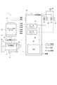
図1および図2に示すように、シフトバイワイヤシステム1は、モータ10、シフトレンジ切替機構20、パーキングロック機構30、および、シフトレンジ制御装置40等を備える。
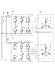
モータ10は、図示しない車両に搭載されるバッテリ45(図3参照。)から電力が供給されることで回転し、シフトレンジ切替機構20の駆動源として機能する。モータ10は、フィードバック制御により電流の大きさを変更可能であって、かつ、相ごとに指令を変更可能なものが用いられる。本実施形態のモータ10は、永久磁石式のDCブラシレスモータである。図3に示すように、モータ10は、2組の巻線組11、12を有する。第1巻線組11は、U1コイル111、V1コイル112、および、W1コイル113を有する。第2巻線組12は、U2コイル121、V2コイル122、および、W2コイル123を有する。
Hereinafter, a shift range control device according to the present invention will be described with reference to the drawings.
(First embodiment)
The shift range control device according to the first embodiment of the present invention is shown in FIGS.
As shown in FIGS. 1 and 2, the shift-by-
The
図2に示すように、エンコーダ13は、モータ10の図示しないロータの回転位置を検出する。エンコーダ13は、例えば磁気式のロータリーエンコーダであって、ロータと一体に回転する磁石と、磁気検出用のホールIC等により構成される。エンコーダ13は、ロータの回転に同期して、所定角度ごとにA相およびB相のパルス信号を出力する。
減速機14は、モータ10のモータ軸と出力軸15との間に設けられ、モータ10の回転を減速して出力軸15に出力する。これにより、モータ10の回転がシフトレンジ切替機構20に伝達される。出力軸15には、出力軸15の角度を検出する出力軸センサ16が設けられる。出力軸センサ16は、例えばポテンショメータである。
As shown in FIG. 2, the
The
図1に示すように、シフトレンジ切替機構20は、ディテントプレート21、および、ディテントスプリング25等を有し、減速機14から出力された回転駆動力を、マニュアルバルブ28、および、パーキングロック機構30へ伝達する。
ディテントプレート21は、出力軸15に固定され、モータ10により駆動される。本実施形態では、ディテントプレート21がディテントスプリング25の基部から離れる方向を正回転方向、基部に近づく方向を逆回転方向とする。
As shown in FIG. 1, the shift
The
ディテントプレート21には、出力軸15と平行に突出するピン24が設けられる。ピン24は、マニュアルバルブ28と接続される。ディテントプレート21がモータ10によって駆動されることで、マニュアルバルブ28は軸方向に往復移動する。すなわち、シフトレンジ切替機構20は、モータ10の回転運動を直線運動に変換してマニュアルバルブ28に伝達する。マニュアルバルブ28は、バルブボディ29に設けられる。マニュアルバルブ28が軸方向に往復移動することで、図示しない油圧クラッチへの油圧供給路が切り替えられ、油圧クラッチの係合状態が切り替わることでシフトレンジが変更される。
ディテントプレート21のディテントスプリング25側には、マニュアルバルブ28を各レンジに対応する位置に保持するための4つの凹部22が設けられる。凹部22は、ディテントスプリング25の基部側から、D、N、R、Pの各レンジに対応している。
The
On the
ディテントスプリング25は、弾性変形可能な板状部材であり、先端にディテントローラ26が設けられる。ディテントローラ26は、凹部22のいずれかに嵌まり込む。
ディテントスプリング25は、ディテントローラ26をディテントプレート21の回動中心側に付勢する。ディテントプレート21に所定以上の回転力が加わると、ディテントスプリング25が弾性変形し、ディテントローラ26が凹部22を移動する。ディテントローラ26が凹部22のいずれかに嵌まり込むことで、ディテントプレート21の揺動が規制され、マニュアルバルブ28の軸方向位置、および、パーキングロック機構30の状態が決定され、自動変速機5のシフトレンジが固定される。
The
The
パーキングロック機構30は、パーキングロッド31、円錐体32、パーキングロックポール33、軸部34、および、パーキングギア35を有する。
パーキングロッド31は、略L字形状に形成され、一端311側がディテントプレート21に固定される。パーキングロッド31の他端312側には、円錐体32が設けられる。円錐体32は、他端312側にいくほど縮径するように形成される。ディテントプレート21が逆回転方向に揺動すると、円錐体32が矢印Pの方向に移動する。
The
The
パーキングロックポール33は、円錐体32の円錐面と当接し、軸部34を中心に揺動可能に設けられる、パーキングロックポール33のパーキングギア35側には、パーキングギア35と噛み合い可能な凸部331が設けられる。ディテントプレート21が逆回転方向に回転し、円錐体32が矢印P方向に移動すると、パーキングロックポール33が押し上げられ、凸部331とパーキングギア35とが噛み合う。一方、ディテントプレート21が正回転方向に回転し、円錐体32が矢印notP方向に移動すると、凸部331とパーキングギア35との噛み合いが解除される。
The
パーキングギア35は、図示しない車軸に設けられ、パーキングロックポール33の凸部331と噛み合い可能に設けられる。パーキングギア35と凸部331とが噛み合うと、車軸の回転が規制される。シフトレンジがP以外のレンジであるnotPレンジのとき、パーキングギア35はパーキングロックポール33によりロックされず、車軸の回転は、パーキングロック機構30により妨げられない。また、シフトレンジがPレンジのとき、パーキングギア35はパーキングロックポール33によってロックされ、車軸の回転が規制される。
The
図2および図3に示すように、シフトレンジ制御装置40は、モータドライバ41、42、および、ECU50等を有する。
モータドライバ41は、第1巻線組11の通電を切り替える3相インバータであって、スイッチング素子411〜416がブリッジ接続される。対になるU相のスイッチング素子411、414の接続点には、U1コイル111の一端が接続される。対になるV相のスイッチング素子412、415の接続点には、V1コイル112の一端が接続される。対になるW相のスイッチング素子413、416の接続点には、W1コイル113の一端が接続される。コイル111〜113の他端は、結線部115で結線される。
As shown in FIGS. 2 and 3, the shift
The
モータドライバ42は、第2巻線組12の通電を切り替える3相インバータであって、スイッチング素子421〜426がブリッジ接続される。対になるU相のスイッチング素子421、424の接続点には、U2コイル121の一端が接続される。対になるV相のスイッチング素子422、425の接続点には、V2コイル122の一端が接続される。対になるW相のスイッチング素子423、426の接続点には、W2コイル123の一端が接続される。コイル121〜123の他端は、結線部125で結線される。
本実施形態のスイッチング素子411〜416、421〜426は、MOSFETであるが、IGBT等の他の素子を用いてもよい。
The
Although the switching
モータドライバ41とバッテリ45との間には、モータリレー46が設けられる。モータドライバ42とバッテリ45との間には、モータリレー47が設けられる。モータリレー46、47は、イグニッションスイッチ等である始動スイッチがオンされているときにオンされ、モータ10側へ電力が供給される。また、モータリレー46、47は、始動スイッチがオフされているときにオフされ、モータ10側への電力の供給が遮断される。
バッテリ45の高電位側には、バッテリ電圧Vを検出する電圧センサ48が設けられる。
また、シフトレンジ制御装置40には、モータ電流Imを検出する図示しない電流センサが設けられる。
A
A
Further, the shift
ECU50は、スイッチング素子411〜416、421〜426のオンオフ作動を制御することで、モータ10の駆動を制御する。また、ECU50は、車速、アクセル開度、および、ドライバ要求シフトレンジ等に基づき、変速用油圧制御ソレノイド6の駆動を制御する。変速用油圧制御ソレノイド6を制御することで、変速段が制御される。変速用油圧制御ソレノイド6は、変速段数等に応じた本数が設けられる。本実施形態では、1つのECU50がモータ10およびソレノイド6の駆動を制御するが、モータ10を制御するモータ制御用のモータECUと、ソレノイド制御用のAT−ECUとを分けてもよい。以下、モータ10の駆動制御を中心に説明する。
The
図4に示すように、ECU50は、角度演算部51、速度演算部52、角度偏差演算部53、フィードバック制御部60、急ブレーキデューティ演算部70、第1切替制御部71、固定相通電制御部75、反転判定部76、および、第2切替制御部77等を備え、マイコン等を主体として構成される。ECU50における各処理は、ROM等の実体的なメモリ装置に予め記憶されたプログラムをCPUで実行することによるソフトウェア処理であってもよいし、専用の電子回路によるハードウェア処理であってもよい。
As shown in FIG. 4, the
角度演算部51は、エンコーダ13から出力されるA相およびB相のパルスに基づき、エンコーダ13のカウント値である実カウント値Cenを演算する。実カウント値Cenは、モータ10の実際の機械角および電気角に応じた値である。
速度演算部52は、実カウント値Cenに基づき、モータ10の回転速度であるモータ速度Mspを演算する。
角度偏差演算部53は、図示しないシフトレバー等の操作により入力されるドライバ要求シフトレンジに応じた目標カウント値Cen*と実カウント値Cenとの差を演算する。以下、目標カウント値Cen*と実カウント値Cenと差の絶対値を角度偏差eとする。
本実施形態では、実カウント値Cenを「実角度」、目標カウント値Cen*を「目標角度」とする。
The
The
The angle deviation calculator 53 calculates the difference between the target count value Cen * and the actual count value Cen corresponding to the driver-requested shift range input by operating a shift lever or the like (not shown). Hereinafter, the absolute value of the difference between the target count value Cen * and the actual count value Cen is referred to as the angle deviation e.
In the present embodiment, the actual count value Cen is the “real angle” and the target count value Cen * is the “target angle”.
フィードバック制御部60は、目標速度設定部62、フィードバック値設定部63、速度偏差演算部64、制御器65、フィードフォワード補正値演算部66、および、フィードフォワード項補正部67等を有する。以下適宜、フィードバックを「FB」、フィードフォワードを「FF」と記載する。
The feedback control unit 60 includes a target speed setting unit 62, a feedback
目標速度設定部62は、角度偏差eに基づき、モータ10の目標速度である目標モータ速度Msp*を演算する。目標モータ速度Msp*は、例えば図5に示すマップに基づき、角度偏差eが所定値ea以下の場合、角度偏差eが大きいほど大きくなるように設定され、角度偏差eが所定値eaより大きい場合、所定の最大値とする。また、角度偏差eが角度判定閾値e_thにて設定速度sp1(例えば1000rpm)となるようにする。
目標モータ速度Msp*は、バッテリ電圧Vが大きくなるほど大きくなるように設定される。
The target speed setting unit 62 calculates the target motor speed Msp * which is the target speed of the
The target motor speed Msp * is set to increase as the battery voltage V increases.
FB値設定部63は、モータ10の制御状態が後述のモード2またはモード3、すなわち定常制御または減速制御のとき、モータ速度Mspの位相を進ませる位相進み補償を行い、速度位相進み値Msp_plを速度フィードバック値Msp_fbとする。また、FB値設定部63は、モータ10の制御状態がモード1、すなわち加速制御のとき、位相進み補償を行わず、モータ速度Mspを速度フィードバック値Msp_fbとする。速度位相進み値Msp_plについても、「モータ速度」の概念に含まれるものとする。
The FB
速度偏差演算部64は、目標モータ速度Msp*と速度フィードバック値Msp_fbとの速度偏差ΔMspを演算する。
制御器65は、目標モータ速度Msp*と速度フィードバック値Msp_fbとを一致させるべく、速度偏差ΔMspが0となるように、例えばP制御やPI制御等により、FBデューティD_fbを演算する。
The
The
FF補正値演算部66は、モータ10の制御状態に応じたFFデューティD_ffを演算する。
加速制御時のFFデューティD_ffは、図6(a)に示すマップ等に基づいて演算される最大加速デューティであって、モータ速度Mspが大きくなるほど大きくなる。本実施形態では、モータ速度Mspが目標モータ速度Msp*以上となるまでの間、最大デューティとなるように、FFデューティD_ffが演算される。
定常制御時のFFデューティD_ffは、図6(b)に示すマップ等に基づいて演算される速度維持デューティとする。速度維持デューティは、無負荷時にモータ速度Mspを維持するためのデューティであって、モータ速度Mspが大きくなるほど大きくなる。
減速制御時のFFデューティD_ffは、図6(c)に示すマップ等に基づいて演算される減速補正デューティとする。減速補正デューティは、目標モータ速度Msp*を実現するための補正デューティである。減速補正デューティは、モータ10が正方向に回転している場合は負の値であって、モータ速度Mspが大きくなるほど小さくなる。すなわち、減速補正デューティは、モータ速度Mspが大きくなるほど、絶対値としては大きい値となる。
The FF correction value calculation unit 66 calculates the FF duty D_ff according to the control state of the
The FF duty D_ff during acceleration control is the maximum acceleration duty calculated based on the map shown in FIG. 6A and the like, and becomes larger as the motor speed Msp increases. In the present embodiment, the FF duty D_ff is calculated so as to have the maximum duty until the motor speed Msp becomes equal to or higher than the target motor speed Msp * .
The FF duty D_ff during steady control is a speed maintenance duty calculated based on the map shown in FIG. The speed maintenance duty is a duty for maintaining the motor speed Msp when there is no load, and increases as the motor speed Msp increases.
The FF duty D_ff during deceleration control is a deceleration correction duty calculated based on the map shown in FIG. The deceleration correction duty is a correction duty for realizing the target motor speed Msp * . The deceleration correction duty is a negative value when the
なお、図6は、モータ10が正方向に回転している場合であって、モータ10が負方向に回転する場合、FFデューティD_ffの値の正負を反転させる。後述の固定デューティDbも同様である。本実施形態では、モータ速度Mspに基づいてFFデューティD_ffを演算するものとして説明したが、モータ速度Mspに替えて、目標モータ速度Msp*に基づいてFFデューティD_ffを演算してもよい。
Note that, in FIG. 6, when the
FF項補正部67は、FBデューティD_fbをFFデューティD_ffで補正し、デューティ指令値を演算する。本実施形態のFF項補正部67は加算器であって、FBデューティD_fbにFFデューティD_ffを加算し、補正後FBデューティDaを演算する。
The FF
本実施形態のフィードバック制御では、PWM制御等によりデューティを変更することで、コイル111〜113、121〜123に流れる電流およびトルクの大きさを変更可能である。
本実施形態では、120°通電による矩形波制御により、モータ10の駆動を制御する。120°通電による矩形波制御では、第1相の高電位側のスイッチング素子と、第2相の低電位側のスイッチング素子をオンする。また、第1相および第2相の組み合わせを電気角60°ごとに入れ替えていくことで、通電相が切り替わる。これにより、巻線組11、12に回転磁界が発生し、モータ10が回転する。本実施形態では、出力軸15を正回転方向に回転させるときのモータ10の回転方向を正方向とする。また、モータ10が正のトルクを出力するときのデューティを正、負のトルクを出力するときのデューティを負とし、取り得るデューティ範囲を−100[%]〜100[%]とする。すなわち、モータ10を正回転させるとき、デューティを正とし、逆回転させるとき、デューティを負とする。なお、正回転しているモータ10を停止させるべく、ブレーキトルク(すなわち負トルク)を発生させるとき、モータ10の回転方向は正回転方向であるが、デューティは負となる。同様に、逆回転しているモータ10を停止させるべく、ブレーキトルクを発生させるとき、デューティは正となる。
In the feedback control of the present embodiment, the magnitude of the current and torque flowing through the
In the present embodiment, the drive of the
急ブレーキデューティ演算部70は、急ブレーキ制御時のデューティである固定デューティDbを、急ブレーキ制御開始時、すなわち角度偏差eが角度判定閾値e_thより小さくなったときのモータ速度Mspである突入速度Msp_iに応じて演算する。図7に示すように、モータ10が正回転しているときの固定デューティDbは、負の値であって、突入速度Msp_iが所定速度sp2より小さい場合、突入速度Msp_iが大きいほど絶対値が大きく、所定速度sp2以上の場合、−100[%]とする。
The sudden braking
第1切替制御部71は、信号生成に用いるデューティを、補正後FBデューティDaとするか、固定デューティDbとするかを切り替える。本実施形態では、角度偏差eが角度判定閾値e_th以上の場合、補正後FBデューティDa、角度偏差eが角度判定閾値e_thより小さい場合、固定デューティDbを、信号生成に用いるデューティとして選択し、電圧補正部72に出力する。
電圧補正部72は、選択された補正後FBデューティDaまたは固定デューティDbを、バッテリ電圧Vにて補正し、デューティ指令値を演算する。
PWM信号生成部73は、デューティ指令値および実カウント値Cenに基づき、スイッチング素子411〜416、421〜426のスイッチングに係る指令信号Spwmを生成する。また、モータ電流Imが電流制限値Im_maxを超えないように指令信号Spwmを調整する。
The first
The
The
固定相通電制御部75は、固定相通電制御を行う。固定相通電制御は、モータ10の回転を停止させるための制御であって、電気角に応じた固定相を選択し、選択された固定相の所定方向に電流が流れるように、スイッチング素子411〜416、421〜426のスイッチングに係る指令信号Sfixを生成する。これにより、励磁相が固定される。励磁相が固定されると、モータ10は、励磁相に応じた所定の電気角にて停止する。固定相通電制御部75は、現在のロータ位置から最も近い電気角でモータ10を停止させるように、実カウント値Cenに基づいて固定相および通電方向を選択する。
また、固定相通電制御では、固定相通電制御開始からデューティ固定時間Tf経過後、デューティを徐変する。具体的には、固定相通電継続時間Ta経過後のモータ電流Imが0となるように、デューティの絶対値を減少させる。
The stationary phase
In the fixed phase energization control, the duty is gradually changed after the fixed duty time Tf has elapsed from the start of the fixed phase energization control. Specifically, the absolute value of the duty is reduced so that the motor current Im after the lapse of the fixed phase energization duration Ta becomes 0.
反転判定部76は、実カウント値Cenに基づき、モータ10の回転が反転したか否かを判定する。
第2切替制御部77は、モータドライバ41、42に出力される信号を切り替える。本実施形態では、モータ10が、要求シフトレンジに応じた回転方向に回転している場合、すなわち反転前である場合、PWM信号生成部73にて生成された指令信号Spwmを選択し、モータ10が反転した場合、固定相通電制御部75にて生成される指令信号Sfixを選択する。選択された指令信号は、モータドライバ41、42に出力される。
The
The second
ここで、モータ10の制御モードをまとめておく。モード1は「加速制御」であって、モータ10の回転を加速させる。モード2は「定常制御」であってモータ10の回転速度を略一定に保持する。モード3は「減速制御」であって、モータ10の回転を減速させる。モード4は「急ブレーキ制御」であって、モータ10の回転に急ブレーキをかける。モード5は「固定相通電制御」であって、モータ10を停止させる。モード0は「通電オフ」であって、モータ10への通電を停止する。
Here, the control modes of the
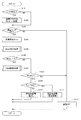
モータ制御処理を図8のフローチャートに基づいて説明する。この処理は、イグニッションスイッチ等である始動スイッチがオンされている期間に、ECU50にて所定の周期で実行される。以下、ステップS101の「ステップ」を省略し、単に記号「S」と記す。他のステップについても同様である。
The motor control process will be described based on the flowchart of FIG. This process is executed by the
最初のS101では、ECU50は、ドライバにより図示しないシフトレバーが操作され、ドライバ要求シフトレンジが変化したか否かを判断する。ドライバ要求シフトレンジが変化していないと判断された場合(S101:NO)、S103へ移行する。ドライバ要求シフトレンジが変化したと判断された場合(S101:YES)、S102へ移行する。
In the first step S101, the
S102では、ECU50は、モータ10への通電フラグをオンにする。また、ECU50は、制御状態を加速制御であるモード1とする。
S103では、ECU50は、通電フラグがオンされているか否かを判断する。通電フラグがオフであると判断された場合(S103:NO)、S112へ移行する。通電フラグがオンであると判断された場合(S103:YES)、S104へ移行する。
S104では、目標速度設定部62は、目標モータ速度Msp*をセットする。
S105では、ECU50は、モード判定処理を行う。
In S102, the
In S103, the
In S104, the target speed setting unit 62 sets the target motor speed Msp * .
In S105, the
モード判定処理を図9に基づいて説明する。
S151では、ECU50は、制御モードがモード1か否かを判断する。制御モードがモード1ではないと判断された場合(S151:NO)、S154へ移行する。制御モードがモード1であると判断された場合(S151:YES)、S152へ移行する。
The mode determination process will be described based on FIG.
In S151, the
S152では、ECU50は、目標モータ速度Msp*が現在のモータ速度Mspより小さいか否かを判断する。目標モータ速度Msp*が現在のモータ速度Msp以上であると判断された場合(S152:NO)、モード1を継続する。目標モータ速度Msp*が現在のモータ速度Mspより小さいと判断された場合(S152:YES)、S153へ移行する。
S153では、ECU50は、制御モードを定常制御であるモード2とする。
In S152, the
In S153, the
制御モードがモード1ではないと判断された場合(S151:NO)に移行するS154では、ECU50は、制御モードをモード2か否かを判断する。制御モードがモード2ではないと判断された場合(S154:NO)、S157へ移行する。制御モードがモード2であると判断された場合(S154:YES)、S155へ移行する。
When it is determined that the control mode is not mode 1 (S151: NO), the
S155では、ECU50は、目標モータ速度の今回値Msp*(n)が、前回値Msp*(n−1)より小さいか否かを判断する。目標モータ速度のMsp*(n)が、前回値Msp*(n−1)以上であると判断された場合(S155:NO)、モード2を継続する。目標モータ速度のMsp*(n)が、前回値Msp*(n−1)より小さいと判断された場合(S155:YES)、S156へ移行する。
S156では、ECU50は、制御モードを減速制御であるモード3とする。
In S155, the
In S156, the
制御モードがモード1、2ではないと判断された場合(S154:NO)に移行するS157では、ECU50は、制御モードがモード3か否かを判断する。制御モードがモード3ではないと判断された場合(S157:NO)、S160へ移行する。制御モードがモード3であると判断された場合(S157:YES)、S158へ移行する。
When the control mode is determined not to be
S158では、ECU50は、角度偏差eが角度判定閾値e_thより小さいか否かを判断する。角度偏差eが角度判定閾値e_th以上であると判断された場合(S158:NO)、モード3を継続する。角度偏差eが角度判定閾値e_thより小さいと判断された場合(S158:YES)、S159へ移行する。
S159では、ECU50は、制御モードを急ブレーキ制御であるモード4とする。
In S158, the
In S159, the
制御モードがモード1〜3ではないと判断された場合(S157:NO)に移行するS160では、ECU50は、制御モードがモード4か否かを判断する。制御モードがモード4ではないと判断された場合(S160:NO)、S163へ移行する。制御モードがモード4であると判断された場合(S160:YES)、S161へ移行する。
When it is determined that the control mode is not the
S161では、ECU50は、反転判定部76は、モータ10が反転したか否かを判断する。ここで、シフトレンジの切り替え前後のレンジに基づいて決定される回転方向とは逆方向にモータ10が回転したら、モータ10が反転したと判断する。モータ10が反転していないと判断された場合(S161:NO)、モード4を継続する。モータ10が反転したと判断された場合(S161:YES)、S162へ移行する。
S162では、ECU50は、制御モードを固定相通電制御であるモード5とする。
In S161, the
In S162, the
制御モードがモード1〜4ではないと判断された場合(S160:NO)に移行するS163では、制御モードはモード5であって、ECU50は、固定相通電制御の継続時間を計時するタイマのカウント値であるタイマ値Tcをインクリメントする。
S164では、ECU50は、タイマ値Tcが継続時間判定閾値Tth1より大きいか否かを判断する。継続時間判定閾値Tth1は、固定相通電制御を継続する固定相通電継続時間Ta(例えば100ms)に応じて設定される値である。タイマ値Tcが継続時間判定閾値Tth1以下であると判断された場合(S164:NO)、モード5を継続する。タイマ値Tcが継続時間判定閾値Th1より大きいと判断された場合(S164:YES)、S165へ移行する。
S165では、ECU50は、制御モードを通電オフ制御であるモード0とする。
When it is determined that the control mode is not
In S164, the
In S165, the
図8に戻り、モード判定処理に続いて移行するS106では、ECU50は、制御モードがモード1〜4のいずれかであるか否かを判断する。制御モードがモード1〜4のとき、モータ10はPWM制御されている。制御モードがモード1〜4以外であると判断された場合(S106:NO)、S108へ移行する。制御モードがモード1〜4のいずれかであると判断(S106:YES)、S107へ移行する。
Returning to FIG. 8, in S106 subsequent to the mode determination process, the
S107では、ECU50は、PWM制御によりモータ10の駆動を制御する。
PWM制御処理を図10に基づいて説明する。
S171では、ECU50は、制御モードがモード1〜3のいずれかであるか否かを判断する。制御モードがモード1〜3のとき、モータ10はフィードバック制御される。制御モードがモード1〜3ではない、すなわちモード4であると判断された場合(S171:NO)、S178へ移行する。制御モードがモード1〜3のいずれかであると判断された場合(S171:YES)、S172へ移行する。
In S107, the
The PWM control process will be described based on FIG.
In S171, the
S172では、ECU50は、制御モードがモード1か否かを判断する。制御モードがモード1であると判断された場合(S172:YES)、S173へ移行する。制御モードがモード1ではない、すなわちモード2またはモード3であると判断された場合(S172:NO)、S174へ移行する。
In S172, the
S173では、フィードバック値設定部63は、モータ速度Mspを速度フィードバック値Msp_fbとして、速度偏差演算部64に出力する。
S174では、フィードバック値設定部63は、モータ速度Mspの位相進み補償値Msp_plを速度フィードバック値Msp_fbとして、速度偏差演算部64に出力する。
In S173, the feedback
In S174, the feedback
S175では、制御器65は、フィードバックデューティD_fbを演算する。
S176では、フィードフォワード補正値演算部66は、制御モードに応じたフィードフォワードデューティD_ffを演算する。
S177では、フィードフォワード項補正部67は、フィードバックデューティD_fbとフィードフォワードデューティD_ffとを加算し、補正後フィードバックデューティDaを演算する。
In S175, the
In S176, the feedforward correction value calculation unit 66 calculates the feedforward duty D_ff according to the control mode.
In S177, the feedforward
制御モードがモード4であると判断された場合(S171:NO)に移行するS178では、急ブレーキデューティ演算部70は、突入速度Msp_iに応じて固定デューティDbを設定する。固定デューティDbが設定されている場合は、設定済みの値を維持する。
S179では、PWM信号生成部73は、演算された補正後フィードバックデューティDaまたは固定デューティDbに基づいて指令信号Spwmを生成する。ECU50は、生成された指令信号Spwmに基づいてモータ10の駆動を制御する。
When the control mode is determined to be the mode 4 (S171: NO), the sudden
In S179, the PWM
図8に戻り、制御モードが1〜4以外であると判断された場合(S106:NO)に移行するす108では、ECU50は、制御モードがモード5か否かを判断する。制御モードがモード5ではない、すなわちモード0であると判断された場合(S108:NO)、S112へ移行する。制御モードがモード5であると判断された場合(S108:YES)、S109へ移行する。
Returning to FIG. 8, when the control mode is determined to be other than 1 to 4 (S106: NO), in step 108, the
S109では、ECU50は、タイマ値Tcが固定判定閾値Tth2より大きいか否かを判断する。固定判定閾値Tth2は、固定相通電にて、最大デューティを継続するデューティ固定時間Tf(例えば20ms)に応じて設定される。デューティ固定時間Tfは、固定相通電継続時間Taより短い。タイマ値Tcが固定判定閾値Tth2以下であると判断された場合(S109:NO)、S110へ移行する。タイマ値Tcが固定判定閾値Tth2より大きいと判断された場合(S109:YES)、S111へ移行する。
In S109, the
S110では、固定相通電制御部75は、実カウント値Cenに応じた固定相に最大デューティで通電する指令信号Sfixを生成する。ECU50は、生成された指令信号Sfixに基づいてモータ10の駆動を制御する。
S111では、固定相通電制御部75は、固定相通電継続時間Taが経過したときの電流を0とすべく、電流が徐々に小さくなるように設定されるデューティにて、実カウント値Cenに応じた固定相に通電する指令信号Sfixを生成する。ECU50は、生成された指令信号Sfixに基づいてモータ10の駆動を制御する。
In S110, the fixed phase
In S111, the stationary phase
通電フラグがオフであると判断された場合(S103:NO)、または、制御モードが1〜5ではない、すなわち制御モードがモード0であると判断された場合(S108:NO)に移行するS112では、ECU50は、モータ10への通電をオフにする。モータ10の通電がオフされている場合はオフ状態を継続する。また、通電フラグをオフにする。
If it is determined that the energization flag is off (S103: NO), or if the control mode is not 1 to 5, that is, if the control mode is mode 0 (S108: NO), the process proceeds to S112. Then, the
モータ制御処理を図11に示すタイムチャートに基づいて説明する。図11は、共通時間軸を横軸とし、(a)がドライバ要求シフトレンジ、(b)が通電フラグ、(c)がモータ10の角度、(d)がモータ速度、(e)がデューティ、(f)がモータ電流、(g)が制御モードを示す。図11では、モータ10の角度をエンコーダ13のカウント値で示す。図13も同様である。
The motor control process will be described based on the time chart shown in FIG. 11, the common time axis is the horizontal axis, (a) is the driver required shift range, (b) is the energization flag, (c) is the angle of the
図11に示すように、時刻x1以前において、ドライバ要求シフトレンジがPレンジで維持されている場合、モータ10の制御状態をモード0の通電オフ制御とする。
時刻x1にて、ドライバ要求シフトレンジがPレンジからDレンジに変化すると、通電フラグがオンされ、制御状態をモード1の加速制御に切り替える。また、ドライバ要求シフトレンジに応じ、目標カウント値Cen*が設定される。加速制御では、ECU50は、最大デューティでのPWM制御にて、モータ10を駆動する。また、加速制御では、位相進み補償を行っていないモータ速度Mspをフィードバックする。
As shown in FIG. 11, when the driver-requested shift range is maintained in the P range before time x1, the control state of the
When the driver request shift range changes from the P range to the D range at time x1, the energization flag is turned on and the control state is switched to the acceleration control of
時刻x2にて、モータ速度Mspが目標モータ速度Msp*より大きくなると、制御状態をモード2の定常制御に切り替える。定常制御では、位相進み補償を行った値である位相進み補償値Msp_plをフィードバックする。
時刻x3にて、目標モータ速度Msp*が低下に転じると、制御状態をモード3の減速制御に切り替える。
本実施形態では、回転角の検出遅れや検出の分解能に起因し、ハンチングが生じやすい定常状態および減速状態にて、位相進み補償を行った位相進み補償値Msp_plをフィードバックする。これにより、定常状態および減速状態におけるハンチングが抑制される。
At time x2, when the motor speed Msp becomes higher than the target motor speed Msp * , the control state is switched to the steady control of mode 2. In the steady control, the phase lead compensation value Msp_pl, which is the value obtained by performing the phase lead compensation, is fed back.
When the target motor speed Msp * starts to decrease at time x3, the control state is switched to the
In the present embodiment, the phase lead compensation value Msp_pl for which phase lead compensation has been performed is fed back in the steady state and deceleration state where hunting is likely to occur due to the detection delay of the rotation angle and the detection resolution. This suppresses hunting in the steady state and the deceleration state.
角度偏差eが角度判定閾値e_thより小さくなる時刻x4では、制御モードをモード4の急ブレーキ制御に切り替える。急ブレーキ制御時は、突入速度Msp_iに応じて設定される固定デューティDbに基づいてモータ10の駆動が制御される。急ブレーキ制御を行うことで、オーバーシュートを抑制することができる。
なお、時刻x1から固定相通電制御に移行する時刻x5までの期間は、PWM制御によりモータ10の駆動が制御される。
At time x4 when the angle deviation e becomes smaller than the angle determination threshold value e_th, the control mode is switched to the sudden braking control of
The drive of the
時刻x5にて、モータ10の反転が判定されると、制御モードをモード5の固定相通電制御に切り替える。本実施形態では、時刻x5から、固定相通電継続時間Taが経過する時刻x7までの間、固定相通電制御を継続する。これにより、モータ10を適切に停止させることができる。
When the reverse rotation of the
ところで、モータ10はバネマス系であるため、図11(e)に二点鎖線で示すように、固定相通電継続時間Taに亘って、最大デューティにて固定相通電を継続した後、時刻x7にて通電をオフにすると、モータ軸が急に解放されることで、振動が発生する。この振動によってモータ軸が駆動されると、出力軸15も駆動される虞がある。
By the way, since the
そこで本実施形態では、固定相通電開始からデューティ固定時間Tfが経過する時刻x6までの第1期間は、最大デューティにて固定相通電を行う。また、固定相通電制御にてデューティ固定時間Tfが経過してから固定相通電継続時間Taとなるまで、すなわち時刻x6から時刻x7までの第2期間は、固定相通電継続時間Taが終了する時刻x7におけるモータ電流Imが0となるように、デューティを0まで徐変させる。図11では、線形的にデューティを徐変させているが、非線形的に徐変させてもよいし、ステップ的に徐変させてもよい。
これにより、固定相通電から通電オフに切り替える際のモータ軸の振動が抑制され、通電オフ時において、モータ軸および出力軸15が停止した状態を適切に維持することができる。
Therefore, in the present embodiment, the fixed phase energization is performed at the maximum duty during the first period from the start of the fixed phase energization to the time x6 when the fixed duty time Tf elapses. Further, in the fixed phase energization control, the fixed phase energization continuation time Ta ends at the fixed phase energization continuation time Ta until the fixed phase energization continuation time Ta is reached, that is, the second period from time x6 to time x7. The duty is gradually changed to 0 so that the motor current Im at x7 becomes 0. Although the duty is gradually changed linearly in FIG. 11, the duty may be changed non-linearly or stepwise.
As a result, vibration of the motor shaft when switching from fixed-phase energization to energization off is suppressed, and the state in which the motor shaft and the
以上説明したように、本実施形態のシフトレンジ制御装置は、モータ10の駆動を制御することでシフトレンジを切り替えるものであって、第1切替制御部71と、反転判定部76と、第2切替制御部77と、を備える。
第1切替制御部71は、目標カウント値Cen*と実カウント値Cenの差である角度偏差eが角度判定閾値e_thより小さくなった場合、フィードバック制御から固定デューティDbでの制御に切り替える。本実施形態の固定デューティDbは、モータ10の回転を停止させるような、急ブレーキデューティである。詳細には、フィードバック制御の開始後の加速制御または定常制御のときのデューティが正であれば、固定デューティDbは負であるといった具合に、固定デューティDbは、要求シフトレンジの切り替え方向に応じてモータ10を回転させるときのデューティとは正負が反対のデューティである。
As described above, the shift range control device of the present embodiment switches the shift range by controlling the drive of the
When the angle deviation e, which is the difference between the target count value Cen * and the actual count value Cen, becomes smaller than the angle determination threshold value e_th, the first
反転判定部76は、モータ10が反転したことを判定する。
第2切替制御部77は、モータ10が反転したと判定された場合、固定デューティDbでの制御から、モータ10の固定相に通電する固定相通電制御に切り替える。
これにより、応答性を高めるとともに、オーバーシュートを抑制し、目標位置にて適切にモータ10を停止させることができる。
The
When it is determined that the
As a result, it is possible to improve the responsiveness, suppress the overshoot, and appropriately stop the
固定デューティDbは、角度偏差eが角度判定閾値e_thより小さいと判定されたときのモータ10の回転速度である突入速度Msp_iに応じて設定される。これにより、モータ速度Mspに応じて、オーバーシュートを抑制し、目標位置にて適切にモータ10を停止させることができる。
The fixed duty Db is set according to the rush speed Msp_i that is the rotation speed of the
シフトレンジ制御装置40は、固定相通電制御を開始してから固定相通電継続時間Taが経過した場合、通電をオフにする。
固定相通電時間T1に亘って固定相通電制御を継続することで、モータ10を確実に停止させることができる。また、固定相通電継続期間Ta経過後は、通電オフとすることで、消費電力を低減することができる。
The shift
By continuing the fixed-phase energization control over the fixed-phase energization time T1, the
固定相通電制御が継続される期間のうち、所定時間であるデューティ固定時間Tfが経過するまでの第1期間におけるデューティを一定とし、デューティ固定時間Tfが経過してから固定相通電制御を終了するまでの第2期間において、モータ10の電流が0に近づくように、デューティを徐変させる。
これにより、固定相通電制御から通電オフに切り替えた際のモータ軸の振動を抑制することができ、通電オフ時においても、所望の位置にて出力軸15が停止した状態を維持することができる。
The fixed phase energization control is terminated after the duty fixed time Tf has elapsed, while the duty in the first period until the duty fixed time Tf, which is the predetermined time, has elapsed is constant during the period during which the fixed phase energization control has continued. In the second period up to, the duty is gradually changed so that the current of the
This can suppress vibration of the motor shaft when switching from fixed phase energization control to energization off, and can maintain the state where the
(第2実施形態)
本発明の第2実施形態を図12および図13に示す。本実施形態では、固定相通電制御が上記実施形態と異なっているので、この点を中心に説明し、その他の点についての説明は省略する。
図12は、本実施形態のモータ制御処理を説明するフローチャートである。図12は、S109に続いて移行するS110およびS111に替えて、S210およびS211とする点を除き、図8と同様である。
(Second embodiment)
A second embodiment of the present invention is shown in FIGS. In this embodiment, the fixed-phase energization control is different from that in the above-described embodiment, and therefore, this point will be mainly described, and description of other points will be omitted.
FIG. 12 is a flowchart illustrating the motor control process of this embodiment. FIG. 12 is the same as FIG. 8 except that S110 and S111 that follow S109 are replaced with S210 and S211.
S109にて、タイマ値Tcが固定判定閾値Tth2以下であると判断された場合(S109:NO)、S210へ移行する。
S210では、固定相通電制御部75は、実カウント値Cenに応じた固定相に第1デューティD1で通電する指令信号Sfixを生成する。本実施形態では、第1デューティD1は、例えば最大デューティである−100[%]とする。ECU50は、生成された指令信号Sfixに基づいてモータ10の駆動を制御する。
When it is determined in S109 that the timer value Tc is less than or equal to the fixed determination threshold Tth2 (S109: NO), the process proceeds to S210.
In S210, the stationary phase
S109にて、タイマ値Tcが固定判定閾値Tth2より大きいと判断された場合(S109:YES)、S211へ移行する。
S211では、固定相通電制御部75は、デューティ固定時間Tf経過前よりも電流を低減すべく、第1デューティD1と符号が等しく絶対値が小さい第2デューティD2にて、実カウント値Cenに応じた固定相に通電する指令信号Sfixを生成する。第2デューティD2は、任意の所定値(例えば−30[%])である。ECU50は、生成された指令信号Sfixに基づいてモータ10の駆動を制御する。
When it is determined in S109 that the timer value Tc is larger than the fixed determination threshold Tth2 (S109: YES), the process proceeds to S211.
In S211, the fixed phase
図13は、本実施形態のモータ制御処理を説明するタイムチャートである。時刻x6までの処理は、第1実施形態と同様である。
図13(e)に示すように、固定相通電制御にて、デューティ固定時間Tfが経過する時刻x6までの第1期間は、最大デューティである第1デューティD1にて固定相通電を行う。また、固定相通電制御にてデューティ固定時間Tfが経過してから固定相通電継続時間Taとなるまで、すなわち時刻x6から時刻x7までの第2期間は、第1デューティD1よりも絶対値が小さい第2デューティD2にて固定相通電制御を行う。第1デューティD1から第2デューティD2に変更することで、図13(f)に示すように、第2期間のモータ電流Imは、第1期間と比較して小さくなるので、第1デューティD1での通電を継続する場合と比較し、通電オフに切り替えた際のモータ軸の振動を抑制することができる。
FIG. 13 is a time chart explaining the motor control process of this embodiment. The process up to time x6 is the same as in the first embodiment.
As shown in FIG. 13E, in the fixed phase energization control, the fixed phase energization is performed at the first duty D1 which is the maximum duty during the first period until time x6 when the fixed duty time Tf elapses. In the fixed phase energization control, the absolute value is smaller than the first duty D1 during the fixed phase energization continuation time Ta until the fixed phase energization continuation time Ta is reached, that is, the second period from time x6 to time x7. Fixed-phase energization control is performed at the second duty D2. By changing the first duty D1 to the second duty D2, the motor current Im in the second period becomes smaller than that in the first period as shown in FIG. 13 (f). It is possible to suppress the vibration of the motor shaft when the energization is switched off as compared with the case where the energization is continued.
本実施形態では、固定相通電制御が継続される期間のうち、所定時間であるデューティ固定時間Tfが経過するまでの第1期間におけるデューティを第1デューティD1とし、デューティ固定時間Tfが経過してから固定相通電制御を終了するまでの第2期間において、第1デューティD1よりも絶対値が小さい第2デューティD2とする。
これにより、固定相通電制御から通電オフに切り替えた際のモータ軸の振動を抑制することができ、通電オフ時においても、所望の位置にて出力軸15が停止した状態を維持することができる。
In the present embodiment, in the period during which the fixed-phase energization control is continued, the duty in the first period until the duty fixed time Tf that is the predetermined time elapses is the first duty D1, and the duty fixed time Tf elapses. During the second period from the end of the fixed phase energization control to the second duty D2, the absolute value is smaller than the first duty D1.
This can suppress vibration of the motor shaft when switching from fixed phase energization control to energization off, and can maintain the state where the
(他の実施形態)
上記実施形態では、モータは、永久磁石式の3相ブラシレスモータである。他の実施形態では、モータは、フィードバック制御と固定相通電制御とを切り替え可能なものであれば、どのようなモータを用いてもよい。また、上記実施形態では、モータに2組の巻線組が設けられる。他の実施形態では、モータの巻線組は、1組でもよいし3組以上であってもよい。
上記実施形態では、フィードバック制御において、120°通電による矩形波制御を行う。他の実施形態では、フィードバック制御において、180°通電による矩形波制御としてもよい。また矩形波制御に限らず、三角波比較方式や瞬時ベクトル選択方式によるPWM制御としてもよい。
(Other embodiments)
In the above embodiment, the motor is a permanent magnet type three-phase brushless motor. In another embodiment, any motor may be used as long as it can switch between feedback control and fixed phase energization control. Further, in the above embodiment, the motor is provided with two winding sets. In other embodiments, the number of winding sets of the motor may be one set or three or more sets.
In the above-described embodiment, in the feedback control, rectangular wave control by energizing 120 ° is performed. In another embodiment, the feedback control may be rectangular wave control by 180 ° energization. Further, the PWM control is not limited to the rectangular wave control, and may be the PWM control by the triangular wave comparison method or the instantaneous vector selection method.
上記実施形態では、モータの回転角を検出する回転角センサとして、エンコーダを用いる。他の実施形態では、回転角センサは、エンコーダに限らず、レゾルバ等、どのようなものを用いてもよい。また、エンコーダのカウント値に替えて、モータの回転角に換算可能なエンコーダカウント値以外の値をフィードバックしてもよい。固定相通電制御における固定相の選択についても同様である。 In the above embodiment, an encoder is used as the rotation angle sensor that detects the rotation angle of the motor. In other embodiments, the rotation angle sensor is not limited to the encoder, and any one such as a resolver may be used. Further, instead of the encoder count value, a value other than the encoder count value that can be converted into the rotation angle of the motor may be fed back. The same applies to the selection of the stationary phase in the stationary phase energization control.
上記実施形態では、速度状態が定常制御または減速制御のとき、位相進みフィルタ処理を行った位相進み値をフィードバックする。他の実施形態では、速度状態が加速制御のときにも位相進みフィルタ処理を行った値をフィードバックしてもよい。また、定常状態および減速状態の少なくとも一方における位相進みフィルタ処理を省略してもよい。
また、速度状態の判定は、例えばモータ速度の微分値を用いて判定する等、判定方法は上記実施形態の方法に限らず、どのような方法であってもよい。
In the above embodiment, when the speed state is the steady control or the deceleration control, the phase lead value subjected to the phase lead filter processing is fed back. In another embodiment, the value obtained by performing the phase lead filter process may be fed back even when the speed state is acceleration control. Further, the phase lead filter processing in at least one of the steady state and the deceleration state may be omitted.
Further, the determination of the speed state is not limited to the method of the above-described embodiment, and the determination method may be any method such as the determination using the differential value of the motor speed.
上記実施形態では、1つの角度判定閾値を用いてフィードバック制御から固定デューティでの急ブレーキ制御への切り替えを判定する。他の実施形態では、角度判定閾値は、例えば、モータ速度が大きくなるほど、角度判定閾値を大きくする、といった具合に、モータ速度に応じて可変としてもよい。
上記実施形態では、急ブレーキ制御における固定デューティは、突入速度に応じて設定される。他の実施形態では、固定デューティは、突入速度によらず、所定値(例えば最大デューティ)であってもよい。
In the above embodiment, the switching from the feedback control to the sudden braking control with a fixed duty is determined using one angle determination threshold value. In another embodiment, the angle determination threshold may be variable according to the motor speed, for example, the angle determination threshold is increased as the motor speed increases.
In the above embodiment, the fixed duty in the sudden braking control is set according to the inrush speed. In another embodiment, the fixed duty may be a predetermined value (for example, maximum duty) regardless of the inrush speed.
上記実施形態では、固定相通電制御では、デューティ固定時間が経過するまでのデューティは、最大デューティである。他の実施形態では、固定相通電制御におけるデューティ固定時間が経過するまでのデューティは、最大デューティでなくてもよい。また、他の実施形態では、固定相通電制御におけるデューティ変更処理を省略し、固定相通電中のデューティが一定であってもよい。 In the above embodiment, in the fixed phase energization control, the duty until the fixed duty time elapses is the maximum duty. In another embodiment, the duty until the fixed duty time in the fixed phase energization control elapses may not be the maximum duty. Further, in another embodiment, the duty changing process in the stationary phase energization control may be omitted, and the duty during the stationary phase energization may be constant.
上記実施形態では、ディテントプレートには4つの凹部が設けられる。他の実施形態では、凹部の数は4つに限らず、いくつであってもよい。例えば、ディテントプレートの凹部を2つとし、PレンジとnotPレンジとを切り替えるものとしてもよい。また、シフトレンジ切替機構やパーキングロック機構等は、上記実施形態と異なっていてもよい。
以上、本発明は、上記実施形態になんら限定されるものではなく、発明の趣旨を逸脱しない範囲において種々の形態で実施可能である。
In the above embodiment, the detent plate is provided with four recesses. In other embodiments, the number of recesses is not limited to four and may be any number. For example, the detent plate may have two recesses and the P range and the notP range may be switched. Further, the shift range switching mechanism, the parking lock mechanism, and the like may be different from those in the above embodiment.
As described above, the present invention is not limited to the above-described embodiment, and can be implemented in various forms without departing from the spirit of the invention.
1・・・シフトバイワイヤシステム
10・・・モータ
20・・・シフトレンジ切替機構
40・・・シフトレンジ制御装置
50・・・ECU
71・・・第1切替制御部
76・・・反転判定部
77・・・第2切替制御部
1 ... Shift-by-
71 ... 1st switching
Claims (5)
前記モータを停止させる目標角度と実角度との差が角度判定閾値より小さくなった場合、フィードバック制御から固定デューティでの制御に切り替える第1切替制御部(71)と、
前記モータが反転したことを判定する反転判定部(76)と、
前記モータが反転したと判定された場合、前記固定デューティでの制御から前記モータの固定相に通電する固定相通電制御に切り替える第2切替制御部(77)と、
を備えることを特徴とするシフトレンジ制御装置。 A shift range control device for switching a shift range by controlling driving of a motor (10),
A first switching control unit (71) for switching from feedback control to control with a fixed duty when the difference between the target angle for stopping the motor and the actual angle becomes smaller than an angle determination threshold value;
A reversal determination unit (76) for determining that the motor has reversed,
A second switching control unit (77) for switching from the control with the fixed duty to the fixed phase energization control for energizing the fixed phase of the motor when it is determined that the motor is reversed.
A shift range control device comprising:
Priority Applications (5)
| Application Number | Priority Date | Filing Date | Title |
|---|---|---|---|
| JP2017029653A JP6690576B2 (en) | 2017-02-21 | 2017-02-21 | Shift range control device |
| CN201880012531.9A CN110337780B (en) | 2017-02-21 | 2018-02-16 | Shift gear control device |
| DE112018000927.0T DE112018000927T5 (en) | 2017-02-21 | 2018-02-16 | Switching range control device |
| PCT/JP2018/005459 WO2018155332A1 (en) | 2017-02-21 | 2018-02-16 | Shift range control device |
| US16/529,904 US10948073B2 (en) | 2017-02-21 | 2019-08-02 | Shift range control device |
Applications Claiming Priority (1)
| Application Number | Priority Date | Filing Date | Title |
|---|---|---|---|
| JP2017029653A JP6690576B2 (en) | 2017-02-21 | 2017-02-21 | Shift range control device |
Publications (3)
| Publication Number | Publication Date |
|---|---|
| JP2018135919A JP2018135919A (en) | 2018-08-30 |
| JP2018135919A5 JP2018135919A5 (en) | 2019-05-09 |
| JP6690576B2 true JP6690576B2 (en) | 2020-04-28 |
Family
ID=63252648
Family Applications (1)
| Application Number | Title | Priority Date | Filing Date |
|---|---|---|---|
| JP2017029653A Active JP6690576B2 (en) | 2017-02-21 | 2017-02-21 | Shift range control device |
Country Status (5)
| Country | Link |
|---|---|
| US (1) | US10948073B2 (en) |
| JP (1) | JP6690576B2 (en) |
| CN (1) | CN110337780B (en) |
| DE (1) | DE112018000927T5 (en) |
| WO (1) | WO2018155332A1 (en) |
Families Citing this family (14)
| Publication number | Priority date | Publication date | Assignee | Title |
|---|---|---|---|---|
| JP6862906B2 (en) | 2017-02-24 | 2021-04-21 | 株式会社デンソー | Shift range controller |
| JP6690590B2 (en) | 2017-03-29 | 2020-04-28 | 株式会社デンソー | Vehicle control device |
| JP6809335B2 (en) | 2017-03-29 | 2021-01-06 | 株式会社デンソー | Vehicle control device |
| JP6708157B2 (en) * | 2017-04-13 | 2020-06-10 | 株式会社デンソー | Shift range control device |
| JP6760232B2 (en) * | 2017-09-05 | 2020-09-23 | 株式会社デンソー | Shift range controller |
| JP7115339B2 (en) * | 2019-01-28 | 2022-08-09 | 株式会社デンソー | shift range controller |
| JP7067382B2 (en) * | 2018-09-18 | 2022-05-16 | 株式会社デンソー | Shift range controller |
| JP7190333B2 (en) * | 2018-11-07 | 2022-12-15 | ミネベアミツミ株式会社 | MOTOR DRIVE CONTROL DEVICE, ELECTRONIC DEVICE, AND MOTOR CONTROL METHOD |
| JP7271834B2 (en) * | 2019-03-29 | 2023-05-12 | ニデックパワートレインシステムズ株式会社 | Electric actuator and actuator device |
| JP7230674B2 (en) | 2019-05-08 | 2023-03-01 | 株式会社デンソー | motor controller |
| JP7226092B2 (en) * | 2019-05-22 | 2023-02-21 | 株式会社デンソー | shift range controller |
| JP7188347B2 (en) * | 2019-10-01 | 2022-12-13 | 株式会社デンソー | shift range controller |
| KR102263101B1 (en) * | 2019-12-03 | 2021-06-09 | 주식회사 현대케피코 | Aparatus and method for learning motor position of electric shift-by-wire system |
| CN114010350B (en) * | 2021-10-28 | 2024-04-30 | 深圳市腾吉思海科技有限公司 | Tooth flushing method and device based on PWM stepless speed regulation |
Family Cites Families (14)
| Publication number | Priority date | Publication date | Assignee | Title |
|---|---|---|---|---|
| JP2004023890A (en) * | 2002-06-17 | 2004-01-22 | Denso Corp | Motor controller |
| US7161314B2 (en) * | 2002-10-07 | 2007-01-09 | Denso Corporation | Motor control apparatus having current supply phase correction |
| JP4385768B2 (en) * | 2004-01-09 | 2009-12-16 | 株式会社デンソー | Motor control device |
| US7659688B2 (en) * | 2007-05-03 | 2010-02-09 | Gm Global Technology Operations, Inc. | Method and system for resolver alignment in electric motor system |
| JP2009017687A (en) * | 2007-07-05 | 2009-01-22 | Victor Co Of Japan Ltd | Disc-rotating device |
| CN100514838C (en) * | 2007-08-03 | 2009-07-15 | 浙江大学 | Electrical servo power-assisted steering controller |
| CN102312847B (en) * | 2011-09-15 | 2013-06-05 | 威海克莱特机电有限公司 | Integral centrifugal fan driven without position sensor |
| JP2014023196A (en) * | 2012-07-13 | 2014-02-03 | Denso Corp | Motor control device |
| CN109075728B (en) * | 2016-04-15 | 2021-12-21 | 株式会社电装 | Shift gear control device |
| JP6658416B2 (en) | 2016-04-15 | 2020-03-04 | 株式会社デンソー | Shift range control device |
| JP6565783B2 (en) * | 2016-04-26 | 2019-08-28 | 株式会社デンソー | Shift range control device |
| JP6601322B2 (en) * | 2016-06-24 | 2019-11-06 | 株式会社デンソー | Shift range switching device |
| JP6690579B2 (en) * | 2017-03-07 | 2020-04-28 | 株式会社デンソー | Shift range control device |
| JP6874674B2 (en) * | 2017-12-27 | 2021-05-19 | 株式会社デンソー | Shift range controller |
-
2017
- 2017-02-21 JP JP2017029653A patent/JP6690576B2/en active Active
-
2018
- 2018-02-16 WO PCT/JP2018/005459 patent/WO2018155332A1/en active Application Filing
- 2018-02-16 CN CN201880012531.9A patent/CN110337780B/en active Active
- 2018-02-16 DE DE112018000927.0T patent/DE112018000927T5/en active Pending
-
2019
- 2019-08-02 US US16/529,904 patent/US10948073B2/en active Active
Also Published As
| Publication number | Publication date |
|---|---|
| DE112018000927T5 (en) | 2019-10-31 |
| US20190353242A1 (en) | 2019-11-21 |
| CN110337780B (en) | 2023-03-14 |
| US10948073B2 (en) | 2021-03-16 |
| WO2018155332A1 (en) | 2018-08-30 |
| JP2018135919A (en) | 2018-08-30 |
| CN110337780A (en) | 2019-10-15 |
Similar Documents
| Publication | Publication Date | Title |
|---|---|---|
| JP6690576B2 (en) | Shift range control device | |
| JP6623987B2 (en) | Shift range control device | |
| JP6862906B2 (en) | Shift range controller | |
| CN109075728B (en) | Shift gear control device | |
| JP6658416B2 (en) | Shift range control device | |
| US11002360B2 (en) | Shift range control apparatus | |
| JP6565841B2 (en) | Shift range control device | |
| JP6569584B2 (en) | Shift range control device | |
| JP6801551B2 (en) | Shift range controller | |
| US11655894B2 (en) | Shift range control device | |
| JP6531707B2 (en) | Shift range control device | |
| JP6673195B2 (en) | Shift range control device | |
| WO2018047916A1 (en) | Shift range control device | |
| JP2019033620A (en) | Motor control device | |
| US12104693B2 (en) | Shift range control device |
Legal Events
| Date | Code | Title | Description |
|---|---|---|---|
| A521 | Request for written amendment filed |
Free format text: JAPANESE INTERMEDIATE CODE: A523 Effective date: 20190319 |
|
| A621 | Written request for application examination |
Free format text: JAPANESE INTERMEDIATE CODE: A621 Effective date: 20190319 |
|
| A131 | Notification of reasons for refusal |
Free format text: JAPANESE INTERMEDIATE CODE: A131 Effective date: 20200107 |
|
| A521 | Request for written amendment filed |
Free format text: JAPANESE INTERMEDIATE CODE: A523 Effective date: 20200220 |
|
| TRDD | Decision of grant or rejection written | ||
| A01 | Written decision to grant a patent or to grant a registration (utility model) |
Free format text: JAPANESE INTERMEDIATE CODE: A01 Effective date: 20200310 |
|
| A61 | First payment of annual fees (during grant procedure) |
Free format text: JAPANESE INTERMEDIATE CODE: A61 Effective date: 20200323 |
|
| R151 | Written notification of patent or utility model registration |
Ref document number: 6690576 Country of ref document: JP Free format text: JAPANESE INTERMEDIATE CODE: R151 |
|
| R250 | Receipt of annual fees |
Free format text: JAPANESE INTERMEDIATE CODE: R250 |