WO2018180442A1 - 検査支援装置、検査支援方法及びプログラム - Google Patents
検査支援装置、検査支援方法及びプログラム Download PDFInfo
- Publication number
- WO2018180442A1 WO2018180442A1 PCT/JP2018/009622 JP2018009622W WO2018180442A1 WO 2018180442 A1 WO2018180442 A1 WO 2018180442A1 JP 2018009622 W JP2018009622 W JP 2018009622W WO 2018180442 A1 WO2018180442 A1 WO 2018180442A1
- Authority
- WO
- WIPO (PCT)
- Prior art keywords
- plane
- dimensional data
- dimensional
- points
- planes
- Prior art date
- Legal status (The legal status is an assumption and is not a legal conclusion. Google has not performed a legal analysis and makes no representation as to the accuracy of the status listed.)
- Ceased
Links
Images






Classifications
-
- G—PHYSICS
- G06—COMPUTING OR CALCULATING; COUNTING
- G06T—IMAGE DATA PROCESSING OR GENERATION, IN GENERAL
- G06T7/00—Image analysis
- G06T7/10—Segmentation; Edge detection
- G06T7/11—Region-based segmentation
-
- G—PHYSICS
- G06—COMPUTING OR CALCULATING; COUNTING
- G06T—IMAGE DATA PROCESSING OR GENERATION, IN GENERAL
- G06T7/00—Image analysis
- G06T7/50—Depth or shape recovery
- G06T7/55—Depth or shape recovery from multiple images
- G06T7/593—Depth or shape recovery from multiple images from stereo images
-
- E—FIXED CONSTRUCTIONS
- E04—BUILDING
- E04G—SCAFFOLDING; FORMS; SHUTTERING; BUILDING IMPLEMENTS OR AIDS, OR THEIR USE; HANDLING BUILDING MATERIALS ON THE SITE; REPAIRING, BREAKING-UP OR OTHER WORK ON EXISTING BUILDINGS
- E04G21/00—Preparing, conveying, or working-up building materials or building elements in situ; Other devices or measures for constructional work
-
- E—FIXED CONSTRUCTIONS
- E04—BUILDING
- E04G—SCAFFOLDING; FORMS; SHUTTERING; BUILDING IMPLEMENTS OR AIDS, OR THEIR USE; HANDLING BUILDING MATERIALS ON THE SITE; REPAIRING, BREAKING-UP OR OTHER WORK ON EXISTING BUILDINGS
- E04G21/00—Preparing, conveying, or working-up building materials or building elements in situ; Other devices or measures for constructional work
- E04G21/12—Mounting of reinforcing inserts; Prestressing
-
- G—PHYSICS
- G06—COMPUTING OR CALCULATING; COUNTING
- G06T—IMAGE DATA PROCESSING OR GENERATION, IN GENERAL
- G06T7/00—Image analysis
- G06T7/0002—Inspection of images, e.g. flaw detection
- G06T7/0004—Industrial image inspection
-
- G—PHYSICS
- G06—COMPUTING OR CALCULATING; COUNTING
- G06T—IMAGE DATA PROCESSING OR GENERATION, IN GENERAL
- G06T7/00—Image analysis
- G06T7/10—Segmentation; Edge detection
- G06T7/194—Segmentation; Edge detection involving foreground-background segmentation
-
- G—PHYSICS
- G06—COMPUTING OR CALCULATING; COUNTING
- G06T—IMAGE DATA PROCESSING OR GENERATION, IN GENERAL
- G06T7/00—Image analysis
- G06T7/60—Analysis of geometric attributes
-
- G—PHYSICS
- G06—COMPUTING OR CALCULATING; COUNTING
- G06T—IMAGE DATA PROCESSING OR GENERATION, IN GENERAL
- G06T2207/00—Indexing scheme for image analysis or image enhancement
- G06T2207/10—Image acquisition modality
- G06T2207/10004—Still image; Photographic image
- G06T2207/10012—Stereo images
-
- G—PHYSICS
- G06—COMPUTING OR CALCULATING; COUNTING
- G06T—IMAGE DATA PROCESSING OR GENERATION, IN GENERAL
- G06T2207/00—Indexing scheme for image analysis or image enhancement
- G06T2207/30—Subject of image; Context of image processing
- G06T2207/30108—Industrial image inspection
Definitions
- the present invention relates to an inspection support apparatus that supports an inspection related to a skeleton of a structure of a building and a civil engineering structure.
- bar arrangement inspection is performed to check whether the reinforcing bars are correctly arranged based on bar arrangement diagrams.
- bar arrangement inspection system a system that supports bar arrangement inspection (hereinafter referred to as “bar arrangement inspection system”) has been developed from the viewpoint of improving inspection efficiency and reducing the burden on the inspector.
- bar arrangement inspection system a technique for performing bar arrangement inspection by analyzing image data of reinforcing bars taken by a digital camera has been actively developed.
- Patent Document 1 proposes a reinforcing bar inspection apparatus that measures the distance between adjacent nodes of a reinforcing bar based on a captured image of the reinforcing bar and derives the diameter of the corresponding reinforcing bar based on the measured distance between the nodes. ing.
- an object of the present invention is to provide an inspection support apparatus that accurately detects a bar arrangement region to be inspected.
- an inspection support apparatus for supporting an inspection relating to a skeleton of a structure of a building and civil engineering
- three-dimensional data of the structure including a plurality of planes formed by the skeleton is acquired and acquired.
- a plurality of first planes calculated based on at least three of the points included in the three-dimensional data are detected from the three-dimensional data, and the first plane is detected for each detected first plane.
- the number of three-dimensional points whose distance from the plane is equal to or less than a predetermined value is calculated, and based on the calculated number of the three-dimensional points, the skeleton of the structure is selected from the plurality of detected first planes.
- the second plane located at the forefront is specified.
- an inspection support apparatus that accurately detects a bar arrangement region to be inspected.
- FIG. 1 is a diagram showing a configuration example of a bar arrangement inspection system 1 according to an embodiment of the present invention.
- the bar arrangement inspection system 1 performs an inspection relating to a skeleton of a structure of a building and a civil engineering structure.
- Reinforcing bar measurement processing includes rebar diameter measurement, rebar count measurement, rebar interval measurement, and the like.
- the bar arrangement inspection system 1 includes an information processing apparatus 10 and a stereo camera 100.
- Stereo camera 100 is an example of a three-dimensional data generation device (also called a three-dimensional sensor).
- a three-dimensional data generation device also called a three-dimensional sensor.
- a 3D laser scanner may be used as the three-dimensional data generation device.
- the reinforcing bar H is photographed by the stereo camera 100, and three-dimensional data of the reinforcing bar H is generated.
- the stereo camera 100 includes a right imaging unit 110R, a left imaging unit 110L, and a three-dimensional data generation unit 120.
- the right imaging unit 110R captures a right eye viewpoint image viewed from the right eye.
- the left imaging unit 110L captures a left-eye viewpoint image viewed from the left eye.
- images captured by the right imaging unit 110R and the left imaging unit 110L may be color images or multi-tone single color images such as gray scale images. In this embodiment, a gray scale image is assumed.
- the three-dimensional data generation unit 120 generates three-dimensional data by performing a known stereo matching process on the image data of the right eye viewpoint image and the image data of the left eye viewpoint image.
- the three-dimensional data is acquired as an image that holds three-dimensional point information in units of pixels.
- Three-dimensional data is also called a three-dimensional image or a distance image.
- the information processing apparatus 10 is, for example, a PC (Personal Computer), a tablet terminal, or dedicated hardware.
- the information processing apparatus 10 acquires the generated three-dimensional data, and based on the acquired three-dimensional data, the measurement target is specified by front parameter calculation processing or the like. Then, the information processing apparatus 10 performs various measurement processes for the reinforcing bars specified as the measurement target. Further, the information processing apparatus 10 may perform processing for displaying or storing the processing result.
- the front bar arrangement HA located at the forefront of the bar arrangement H is the measurement target.
- the front bar arrangement HA is a bar arrangement facing the side closest to the stereo camera 100.
- the information processing apparatus 10 acquires three-dimensional data from the stereo camera 100 as a wired (for example, a USB cable or the Internet), wireless (for example, a wireless LAN (Local Area Network) or the Internet), or an external device. Any of the recording media may be used.
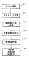
- FIG. 2 is a flow for explaining main processing of the bar arrangement inspection system 1 as a whole.
- the photographer performs stereo shooting of the reinforcing bar H using the stereo camera 100 described above (step S1).
- the stereo camera 100 captures the right-eye viewpoint image and the left-eye viewpoint image, and generates three-dimensional data.
- the information processing apparatus 10 acquires three-dimensional data from the stereo camera 100 (step S2).
- the information processing apparatus 10 specifies the foreground plane from the three-dimensional data (step S3).
- the foreground plane refers to a plane positioned at the forefront with respect to the stereo camera 100 among the planes formed by the skeletons of the structures of civil engineering and civil engineering. Specifically, the foremost plane is a plane including the front bar arrangement HA in FIG.
- the information processing apparatus 10 creates a planar region image based on the identified foreground plane (step S4), and identifies the arrangement of reinforcing bars to be measured (step S5).
- the planar area image will be described with reference to FIGS.
- the information processing apparatus 10 performs various measurement processes such as diameter measurement, number measurement, and interval measurement of the target reinforcing bars based on the specified reinforcing bar arrangement (step S6).
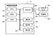
- FIG. 3 is a block diagram illustrating a hardware configuration example of the information processing apparatus 10.
- the information processing apparatus 10 includes a CPU (Central Processing Unit) 510, a RAM (Random Access Memory) 520, a ROM (Read Only Memory) 530, an input / output IF (Interface) 540, a communication unit 550, an operation unit 560, a display unit 570, and the like.
- a bus 580 is included.
- the CPU 510 is a control unit that controls the information processing apparatus 10 as a whole.
- CPU 510 reads a control program from ROM 530 and executes various control processes in accordance with the read control program.
- the RAM 520 is a work area that temporarily stores various data such as a control program and three-dimensional data from the stereo camera 100.
- the RAM 520 is, for example, a DRAM (Dynamic Random Access Memory).
- the ROM 530 is a non-volatile storage unit that stores a control program, data, and the like.
- the ROM 530 is, for example, a flash memory.
- the input / output IF 540 transmits / receives data to / from an external device.
- the external device is, for example, a stereo camera 100 connected by a USB cable or the like, or a replaceable storage unit 600.
- the information processing apparatus 10 acquires three-dimensional data from the stereo camera 100 through the input / output IF 540.
- the input / output IF 540 is also called a three-dimensional data acquisition unit.
- the storage unit 600 is a recording medium called a so-called memory card.
- the storage unit 600 may be an HDD (Hard Disk Disk Drive).
- the storage unit 600 may store three-dimensional data generated by the stereo camera 100 and a planar area image generated by the information processing apparatus 10 based on the three-dimensional data.
- the communication unit 550 communicates various data wirelessly with an external device.
- the operation unit 560 is a keyboard or a touch panel for inputting operation instructions.
- the display unit 570 is an LCD (liquid crystal display), for example, and displays input data, a captured image, an image based on three-dimensional data, or the like.
- the CPU 510 is connected to the RAM 520, the ROM 530, etc. via a bus 580.
- FIG. 4 is a functional block diagram relating to bar arrangement inspection processing by the information processing apparatus 10 in the bar arrangement inspection system 1.
- the bar arrangement inspection processing is performed by software processing in which the CPU 510 reads a control program and the CPU 510 executes the read control program.
- the bar arrangement inspection process is realized by a three-dimensional information acquisition unit 32, a plurality of plane detection units 34, a front surface specification unit 36, a plane area image creation unit 38, a reinforcing bar arrangement specification unit 40, a measurement unit 42, and the like. Is done.
- Each unit from the three-dimensional information acquisition unit 32 to the measurement unit 42 is a function realized by software processing.
- the inspection support device 30 is collectively included. Also called.
- the 3D information acquisition unit 32 acquires 3D data from the stereo camera 100.
- the three-dimensional information acquisition unit 32 is, for example, the input / output IF 540 as described above.
- the multi-plane detection unit 34 detects a plurality of planes including at least three points of 3D data from the acquired 3D data. Specifically, for example, the multiple plane detection unit 34 selects three points from the acquired three-dimensional data, sets a provisional plane (also referred to as a first plane) constituted by the three points, and A plurality of provisional planes are detected.
- a provisional plane also referred to as a first plane
- the multiple plane detection unit 34 extracts, from the three-dimensional data, a three-dimensional point whose distance from the temporary plane is a predetermined value or less as a three-dimensional point belonging to the temporary plane.
- a three-dimensional point is each point of three-dimensional data.
- the multiple plane detection unit 34 calculates the number of three-dimensional points belonging to each temporary plane.
- the multiple plane detection unit 34 outputs the detected temporary plane parameters (referred to as plane parameters) and the number of three-dimensional points belonging to each temporary plane.
- the front surface specifying unit 36 specifies the frontmost plane from the plurality of provisional planes output from the multiple plane detection unit 34. Specifically, the front surface specifying unit 36 is based on the number of three-dimensional points belonging to each temporary plane, and is a plane positioned on the forefront in the skeleton of the structure from a plurality of detected temporary planes ( Identify the foreground plane. The foreground plane is also referred to as a second plane. More specifically, the front surface specifying unit 36 specifies a provisional plane having the largest number of calculated three-dimensional points as a frontmost plane among a plurality of detected provisional planes. The front surface specifying unit 36 outputs the specified plane parameter of the foremost plane to the flat region image creating unit 38 as the reinforcement front surface information.
- the foreground plane parameter is also referred to as a front parameter, and the multiple plane detector 34 and the front identifier 36 are collectively referred to as a front parameter detector 50.
- the processing by the front parameter detection device 50 is also called front parameter detection.
- the plane area image creating unit 38 creates an image of the front bar arrangement HA from the acquired three-dimensional data based on the foreground plane parameter.
- the reinforcing bar arrangement specifying unit 40 specifies the reinforcing bar arrangement from the image of the front reinforcing bar HA.
- the measurement unit 42 performs various measurement processes such as the diameter measurement, the number measurement, and the interval measurement of the reinforcing bars based on the specified reinforcing bar arrangement.
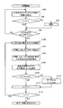
- FIG. 5 is a flowchart for explaining the procedure of front parameter detection processing.
- the front parameter detection process is performed by the front parameter detection device 50 (multi-plane detection unit 34 and front surface specifying unit 36).
- the multi-plane detection unit 34 and the front surface specification unit 36 initialize the loop processing variables (t, N).
- the multi-plane detection unit 34 selects at least three points from the three-dimensional point set ⁇ (step S100).
- the multiple plane detection unit 34 calculates parameters of the multiple planes L_tmp based on the selected points (step S102).
- the plane L_tmp is the provisional plane described above.
- the parameters of the plane L_tmp are coefficients a, b, c, and d of the plane equation represented by the following formula (1).
- ax + by + cz + d 0
- (x, y, z) indicates the coordinates of a point in the three-dimensional space.
- the parameters of the plane L_tmp can be calculated using a known technique such as a least square method. When the selected points are three points, one plane can be calculated. Note that the number of points to be selected is not limited to three, and may be three or more.
- the multiple plane detection unit 34 calculates the distance between the plane L_tmp and each point of the three-dimensional point set ⁇ (step S104).
- the multiple plane detection unit 34 calculates the number N_tmp of points whose distance from the plane L_tmp is equal to or less than the threshold D in the set of three-dimensional points ⁇ (step S106). That is, the multiple plane detection unit 34 calculates the number of three-dimensional points close to the plane L_tmp.
- the threshold value D is a preset value and may be stored in the ROM 530.
- the threshold value D may be, for example, the radius or diameter of the target reinforcing bar.
- a three-dimensional point whose distance from the plane L_tmp is equal to or less than the threshold value D is referred to as a proximity point.
- the number N_tmp of adjacent points satisfying the following formula (2) is calculated from the three-dimensional point set ⁇ .
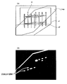
- Steps S100 to S106 will be described as specific examples with reference to FIGS. 6 and 7 are diagrams illustrating the relationship between the plane L_tmp and the number N_tmp of neighboring points corresponding to the plane L_tmp.
- a plane L_tmp shown in the image D4 of FIG. 6 is a slope that crosses the reinforcement H diagonally from the lower front surface of the reinforcement H toward the upper rear surface of the reinforcement H.
- a plane L_tmp shown in the image D6 of FIG. 7 is a plane parallel to the floor surface e2 and close to the floor surface e2.
- the image D5 in FIG. 6 shows the area of the proximity point calculated on the plane L_tmp (slope) of the image D4 in white.
- a region where the plane L_tmp of the image D4 intersects the reinforcing bar H, and a region where the plane L_tmp intersects the wall surface e1 corresponds to the region of the proximity point of the plane L_tmp (slope).
- the number N_tmp of adjacent points was calculated as 84,032 points.
- the image D7 in FIG. 7 shows the area of the proximity point calculated on the plane L_tmp of the image D6 in white. Since the plane L_tmp is close to the floor surface e2, the area of the floor surface e2 is included in the area of the proximity point. In the actual calculation example, the number N_tmp of adjacent points was calculated as 310,075 points. *
- FIG. 7 shows that it is desirable to exclude floors and walls.
- the multiple plane detection unit 34 excludes floor surfaces and wall surfaces based on the coordinate values of the three-dimensional data.
- the multi-plane detection unit 34 may estimate and exclude a plane L_tmp having a predetermined number of adjacent points N_tmp as a floor surface or a wall surface.
- step S110 and subsequent steps in FIG. 5 the temporary plane having the largest number of adjacent points N_tmp is selected from the temporary planes excluding the floor and wall surfaces, and the selected temporary plane is identified as the forefront plane of the bar arrangement. To do. The reason will be explained.
- the number N_tmp of adjacent points decreases.
- the number of adjacent points N_tmp increases. That is, the number N_tmp of adjacent points increases as the provisional plane is parallel to the surface of the bar arrangement.
- the front reinforcing bar closer to the stereo camera 100 is photographed with a size (rebar thickness, reinforcing bar length) larger than the rear reinforcing bar (see FIG. 9). That is, the number of adjacent points N_tmp is greater in the front reinforcing bars than in the rear reinforcing bars. From the above, it can be estimated that the provisional plane having the largest number of adjacent points N_tmp is the frontmost plane of the bar arrangement.
- the front surface specifying unit 36 compares the calculated number N_tmp of adjacent points of the plane L_tmp in order, and specifies the plane L_tmp having the largest number of adjacent points N_tmp as the frontmost plane. To do.
- the front surface specifying unit 36 determines whether N ⁇ N_tmp (Step S108). N is a provisional maximum value of the number N_tmp of adjacent points. If the front surface specifying unit 36 determines that N ⁇ N_tmp (YES in step S108), the front surface specifying unit 36 updates N with N_tmp and updates the plane L with the plane L_tmp (step S110).
- the plane L is a provisional foreground plane parameter.
- t is a loop counter for comparing N_tmp of the plane L_tmp in order.
- step S108 If the front face specifying unit 36 determines that N ⁇ N_tmp is not satisfied (NO in step S108), the process proceeds to step S112. After step S112, when the front surface specifying unit 36 determines that t ⁇ T is not satisfied (NO in step S114), the front surface L is specified as a plane parameter corresponding to the front surface of the bar arrangement, and is output to the flat region image creating unit 38. . This completes the front parameter detection process.
- steps S100 to S114 described above are common to the process of the parameter estimation method by the RANSAC (Random Sample Consensus) process.
- the RANSAC process is originally developed and used to estimate a numerical model from measured values including outliers.
- processing equivalent to the RANSAC processing is performed with an intention different from the intention of the original RANSAC processing.
- FIG. 8 is an example of a plane area image created by the plane area image creation unit 38.
- the image D8 is a diagram illustrating a plane L set to include a three-dimensional image of the bar arrangement H and the front bar arrangement of the bar arrangement H.
- the image D9 is a plane area image corresponding to the plane L of the image D8.
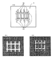
- FIG. 9 is a diagram comparing a plane area image (image D11) obtained by the front bar arrangement HA of the reinforcing bar H and a plane area image (image D12) obtained by the rear bar arrangement HB.
- the image D10 is a three-dimensional image that is the basis of the image D11 and the image D12. Since the front reinforcing bar HA has a shorter distance to the stereo camera 100 than the rear reinforcing bar HB, the size of the reinforcing bar is displayed larger than the rear reinforcing bar HB. That is, the image D11 has a larger area displayed as a reinforcing bar than the image D12. That is, the number N_tmp of adjacent points in the image D11 is larger than the number N_tmp of adjacent points in the image D12. From the above, it is possible to identify the plane having the largest number of adjacent points N_tmp as the foreground plane.
- the front parameter detection process described above is summarized as follows. -Select any three or more points from the input three-dimensional data, and calculate plane parameters based on these points. Calculate the distance to the calculated plane for the input 3D data, and count the number of points whose distance is less than or equal to the threshold. The above-described plane parameter calculation and counting of the number of points whose distance from the plane is less than or equal to the threshold value are repeated while reselecting any three or more three-dimensional points. As a result, a plurality of sets of plane parameter / number pairs are calculated. -The plane parameter of the pair with the largest number among the above-mentioned pairs of plane parameter and number is acquired as a plane corresponding to the front of the bar arrangement.
- the frontmost bar arrangement is automatically detected by utilizing the largest amount of three-dimensional point data corresponding to the front surface in the acquired three-dimensional data. Thereby, the foreground bar arrangement is reliably detected by the front surface parameter detection processing of the present embodiment.
- the multi-plane detection unit 34 previously removes the floor surface and the wall surface from the temporary plane. Furthermore, in the second embodiment, three-dimensional data separated by a predetermined distance or more from the three-dimensional data generation apparatus (stereo camera 100) is excluded from the three-dimensional point set ⁇ used by the multiple plane detection unit 34. This is because, since the measurement target is the foreground reinforcement, a three-dimensional point that is more than a predetermined depth from the stereo camera 100 is unnecessary.
- FIG. 10 is a functional block diagram relating to bar arrangement inspection processing according to the second embodiment.
- the inspection support apparatus 30b according to the second embodiment is obtained by adding a three-dimensional data removal unit 70 to the inspection support apparatus 30 according to the first embodiment.
- the three-dimensional data removal unit 70 identifies three-dimensional data that is a predetermined distance away from the three-dimensional data generation apparatus (stereo camera 100), and excludes the identified three-dimensional data from the three-dimensional point set ⁇ . Then, the three-dimensional data removal unit 70 outputs the set of three-dimensional points ⁇ excluding the specified three-dimensional data to the multiple plane detection unit 34.
- the predetermined distance is 3 m when the distance to the front reinforcement HA is 2 m, for example.
- FIG. 11 is a flowchart for explaining the procedure of front parameter detection processing in the second embodiment. Steps S80 to S86 are processing unique to the second embodiment. Steps S100 to S114 are the same processing as in the first embodiment.
- the three-dimensional data removal unit 70 reads out three-dimensional points one by one from the three-dimensional point set ⁇ , and performs the following steps S80 to S86. *
- the three-dimensional data removal unit 70 calculates the distance K between the three-dimensional point and the stereo camera 100 from the coordinates of the three-dimensional point (x, y, z) (step S80).
- the three-dimensional data removal unit 70 determines whether or not K ⁇ P (step S82).
- P is a value obtained by adding a certain margin value to the distance to the front reinforcing bar HA located at the forefront.
- the distance to the front reinforcement HA may be a distance measured by the stereo camera 100 or may be an input value from the photographer.
- step S82 If the three-dimensional data removal unit 70 determines that K ⁇ P is not satisfied (NO in step S82), the three-dimensional point is removed (step S84), and the process proceeds to step S86. This is because it is possible to determine that the three-dimensional point is not included in the front reinforcing bar HA.
- step S86 determines whether the processing for all of the three-dimensional points is completed. If the three-dimensional data removal unit 70 determines that the processing for all of the three-dimensional points has not been completed (NO in step S86), the three-dimensional data removal unit 70 returns to step S80. If the three-dimensional data removal unit 70 determines that the processing for all of the three-dimensional points has been completed (YES in step S86), the process proceeds to step S100. Steps S100 and after are already described, and will be omitted.
- the three-dimensional data removal unit 70 can efficiently exclude the three-dimensional data by the rear reinforcement and the wall surface. By excluding unnecessary three-dimensional points in advance, the number of three-dimensional data is reduced, and the time required for front parameter detection processing is reduced. Note that the above-described removal process may be performed in the multi-plane detection unit 34 (in the RANSAC process).
- the information processing apparatus 10 and the stereo camera 100 have been described as separate bodies, but may be an integrated apparatus (a tablet terminal with a built-in stereo camera).
- inspection assistance apparatus 30 (30b) was demonstrated implement
- the inspection support apparatus 30 (30b) may be partially or entirely executed by hardware processing (for example, a gate array circuit).
Landscapes
- Engineering & Computer Science (AREA)
- Physics & Mathematics (AREA)
- Computer Vision & Pattern Recognition (AREA)
- General Physics & Mathematics (AREA)
- Theoretical Computer Science (AREA)
- Architecture (AREA)
- Civil Engineering (AREA)
- Mechanical Engineering (AREA)
- Structural Engineering (AREA)
- Quality & Reliability (AREA)
- Geometry (AREA)
- Length Measuring Devices By Optical Means (AREA)
- Image Analysis (AREA)
- Management, Administration, Business Operations System, And Electronic Commerce (AREA)
- Conveying And Assembling Of Building Elements In Situ (AREA)
Abstract
建築及び土木の構造体の骨格に関する検査を支援する検査支援装置において、骨格で形成される複数の平面を含む前記構造体の3次元データを取得する三次元情報取得部32と、取得された三次元データから、三次元データを少なくとも3点含む第1の平面を複数検出し、検出された第1の平面毎に、前記三次元データの中から第1の平面との距離が所定以下となる3次元点の個数を算出する複数平面検出部34と、算出された前記三次元点の個数に基づいて、検出された複数の第1の平面の中から、構造体の骨格で最前面に位置する第2の平面を特定する前面特定部36を備える。
Description
本発明は、建築及び土木の構造体の骨格に関する検査を支援する検査支援装置に関する。
鉄筋コンクリート造の建築物の工事においては、配筋図等に基づいて正しく鉄筋が配置されているかをチェックする配筋検査が行われている。このような配筋検査では、検査の効率化や検査者の負担軽減等の観点から、配筋検査を支援するシステム(以下、「配筋検査システム」という)が開発されている。この配筋検査システムとして、デジタルカメラで撮影された鉄筋の画像データを解析して配筋検査を行う技術が盛んに開発されている。
例えば、特許文献1では、鉄筋の撮影画像に基づいて、鉄筋の隣接する節の間の距離を計測し、計測した節間の距離によって、対応する鉄筋の径を導出する鉄筋検査装置が提案されている。
通常、配筋は、前面・後面・側面等のように、複数の層(面)に分けられて施工される。配筋検査は前面層を対象として実施されることが多いが、前面層の配筋のみを現場で撮影することは難しく、撮影画像には各層の鉄筋が混在することが多い。そのため、撮影画像に基づき配筋検査を行う場合には、検査対象の層に属する鉄筋を正しく抽出する必要がある。例えば、上記特許文献1では、配筋前面領域を検出するために、最初に前面領域に属する三次元点を手動で指定している。しかし、検査対象の配筋領域を手動に指定する方式は、検査の自動化の妨げになり、また誤りも起きやすい。
本願発明は、上記課題に鑑み、検査対象の配筋領域を的確に検出する検査支援装置を提供することを目的とする。
本願発明は、上記課題に鑑み、検査対象の配筋領域を的確に検出する検査支援装置を提供することを目的とする。
上記目的を達成するために、建築及び土木の構造体の骨格に関する検査を支援する検査支援装置において、前記骨格で形成される複数の平面を含む前記構造体の三次元データを取得し、取得された前記三次元データから、前記三次元データに含まれる点のうち少なくとも3点に基づいて算出される第1の平面を複数検出し、検出された前記第1の平面毎に、当該第1の平面との距離が所定以下の三次元点の個数を算出し、算出された前記三次元点の個数に基づいて、検出された複数の前記第1の平面の中から、前記構造体の骨格で最前面に位置する第2の平面を特定する。
本発明によれば、検査対象の配筋領域を的確に検出する検査支援装置を提供することができる。
以下、図面に従って本発明の実施形態を説明する。図1は、本発明の一実施の形態に係る配筋検査システム1の構成例を示す図である。配筋検査システム1は、建築及び土木の構造体の骨格に関する検査を行うものである。以下では、配筋検査システム1の具体例として、配筋された鉄筋を撮影して、撮影画像に基づき鉄筋の計測処理を行う例を説明する。配筋の計測処理とは、鉄筋の径計測、鉄筋の本数計測、鉄筋の間隔計測等である。
配筋検査システム1は、情報処理装置10とステレオカメラ100を有する。ステレオカメラ100は、三次元データ生成装置(三次元センサとも呼ばれる)の一例である。三次元データ生成装置としては、3Dレーザースキャナでもよい。
ステレオカメラ100によって、配筋Hが撮影され、配筋Hの三次元データが生成される。ステレオカメラ100は、右撮像部110R、左撮像部110L、三次元データ生成部120を有する。右撮像部110Rは、右目から見た右目視点画像を撮影する。左撮像部110Lは、左目から見た左目視点画像を撮影する。なお、右撮像部110R及び左撮像部110Lで撮影される画像は、カラー画像でもよいし、グレースケール画像等の多階調単色画像でもよい。本実施形態では、グレースケール画像とする。
三次元データ生成部120は、右目視点画像の画像データと左目視点画像の画像データに対して公知のステレオマッチング処理を行うことにより、三次元データを生成する。なお、三次元データは、画素単位で三次元点情報を保持する画像として取得される。三次元データは、三次元画像や、距離画像とも呼ばれる。
情報処理装置10は、例えばPC(Personal Computer)、タブレット端末、或いは専用ハードウェア等である。情報処理装置10によって、生成された三次元データが取得され、取得された三次元データに基づき、前面パラメーター算出処理等により計測対象が特定される。そして、情報処理装置10によって、計測対象として特定された鉄筋の各種計測処理を行われる。また、情報処理装置10によって、その処理結果を表示あるいは記憶する処理等が行われてもよい。以下では、配筋Hの最前面に位置する前面配筋HAを計測対象とする。前面配筋HAとは、ステレオカメラ100に対し最も近い側に面する配筋である。
なお、情報処理装置10がステレオカメラ100からの三次元データを取得する手段としては、有線(例えば、USBケーブルやインターネット)、無線(例えば、無線LAN(Local Area Network)やインターネット)、あるいは外付け記録媒体のいずれでもよい。
次に、配筋検査システム1における全体処理を簡単に説明する。図2は、配筋検査システム1全体の主な処理を説明するフローである。
撮影者によって、前述のステレオカメラ100を使って、配筋Hのステレオ撮影が行われる(ステップS1)。ステレオカメラ100で、右目視点画像と左目視点画像が撮影され、三次元データが生成される。情報処理装置10は、ステレオカメラ100から三次元データを取得する(ステップS2)。情報処理装置10は、三次元データから、最前面の平面を特定する(ステップS3)。最前面の平面とは、建築及び土木の構造体の骨格で形成される平面の中で、ステレオカメラ100に対して最前面に位置する平面をいう。具体的には、最前面の平面とは図1の前面配筋HAを含む平面である。
情報処理装置10は、特定した最前面の平面に基づき、平面領域画像を作成し(ステップS4)、計測対象となる鉄筋の配置を特定する(ステップS5)。平面領域画像については、図8や図9で説明する。情報処理装置10は、特定した鉄筋配置に基づき、対象となる鉄筋の径計測、本数計測、間隔計測等の各種計測処理を行う(ステップS6)。
図3は、情報処理装置10のハードウェア構成例を示すブロック図である。情報処理装置10は、CPU(Central Processing Unit)510、RAM(Random Access Memory)520、ROM(Read Only memory)530、入出力IF(Interface)540、通信部550、操作部560、表示部570及びバス580を有する。
CPU510は、情報処理装置10全体を統括的に制御する制御部である。CPU510は、ROM530から制御プログラムを読込み、読込んだ制御プログラムに従って、各種制御処理を実行する。
RAM520は、制御プログラムや、ステレオカメラ100からの三次元データ等の各種データを一時的に記憶するワークエリアである。RAM520は、例えばDRAM(Dynamic Random Access Memory)である。ROM530は、制御プログラムやデータ等を記憶する不揮発性の記憶部である。ROM530は、例えばフラッシュメモリである。
入出力IF540は、外部機器とのデータの送受信を行うものである。外部機器は、例えばUSBケーブル等で接続されるステレオカメラ100、あるいは交換可能な記憶部600である。情報処理装置10は、入出力IF540によって、ステレオカメラ100から三次元データを取得する。入出力IF540は、三次元データ取得部とも呼ぶ。記憶部600は、いわゆるメモリカードと呼ばれる記録媒体である。記憶部600は、HDD(Hard Disk Drive)でもよい。記憶部600には、ステレオカメラ100で生成された三次元データや、三次元データに基づき情報処理装置10で生成された平面領域画像が記憶されてもよい。
通信部550は、外部機器と無線で各種データの通信を行うものである。操作部560は、操作指示を入力するキーボードやタッチパネルである。表示部570は、例えばLCD(liquid crystal display)で、入力データあるいは撮影画像や三次元データによる画像等が表示される。CPU510は、RAM520、ROM530等々とバス580で接続される。
図4は、配筋検査システム1における、情報処理装置10による配筋検査処理に関する機能ブロック図である。配筋検査処理は、CPU510が制御プログラムを読込み、CPU510が読込んだ制御プログラムを実行することによるフトウェア処理によって行われる。
図4に示すように、配筋検査処理は、三次元情報取得部32、複数平面検出部34、前面特定部36、平面領域画像作成部38、鉄筋配置特定部40及び計測部42等により実現される。上記の三次元情報取得部32から計測部42の各部は、ソフトウェア処理により実現される機能である。また、三次元情報取得部32、複数平面検出部34及び前面特定部36は、後述するように最前面の平面を特定して配筋検査を支援するものであるので、まとめて検査支援装置30とも呼ぶ。
三次元情報取得部32は、ステレオカメラ100から三次元データを取得する。三次元情報取得部32は、前述のように例えば入出力IF540である。
複数平面検出部34は、取得された三次元データから、三次元データを少なくとも3点含む平面を複数検出する。具体的には、例えば、複数平面検出部34は、取得された三次元データから3点を選択し、3点により構成される仮平面(第1の平面とも呼ぶ)を設定し、このような仮平面を複数検出する。
そして、複数平面検出部34は、検出した仮平面毎に、仮平面に所属する三次元点として、仮平面との距離が所定以下となる三次元点を三次元データから抽出する。三次元点とは、三次元データの各点である。複数平面検出部34は、各仮平面に属する三次元点の個数を算出する。複数平面検出部34は、検出した仮平面のパラメーター(平面パラメーターと呼ぶ)と、各仮平面に所属する三次元点の個数を出力する。
前面特定部36は、複数平面検出部34から出力された複数の仮平面の中から、最前面の平面を特定する。具体的には、前面特定部36は、各仮平面に所属する三次元点の個数に基づいて、検出された複数の仮平面の中から、前記構造体の骨格で最前面に位置する平面(最前面の平面)を特定する。最前面の平面を、第2の平面とも呼ぶ。より具体的には、前面特定部36は、検出された複数の仮平面の中で、算出された三次元点の個数が一番多い仮平面を、最前面の平面と特定する。前面特定部36は、特定した最前面の平面の平面パラメーターを配筋前面情報として、平面領域画像作成部38に出力する。
なお、最前面の平面パラメーターを前面パラメーターとも呼び、複数平面検出部34と前面特定部36を合わせて前面パラメーター検出装置50とも呼ぶ。前面パラメーター検出装置50による処理を前面パラメーター検出とも呼ぶ。
平面領域画像作成部38は、最前面の平面パラメーターに基づき、前面配筋HAの画像を、取得された三次元データから作成する。鉄筋配置特定部40は、前面配筋HAの画像から、鉄筋配置を特定する。計測部42は、特定した鉄筋配置に基づき、鉄筋の径計測、本数計測、間隔計測等の各種計測処理を行う。
図5は、前面パラメーター検出処理の手順を説明するフローチャートである。前面パラメーター検出処理は、前面パラメーター検出装置50(複数平面検出部34と前面特定部36)により行われる。
まず、複数平面検出部34と前面特定部36は、ループ処理用変数(t、N)の初期化を行う。複数平面検出部34は、三次元点の集合φから少なくとも3点を選択する(ステップS100)。複数平面検出部34は、前記選択した点に基づいて、複数の平面L_tmpのパラメーターを算出する(ステップS102)。平面L_tmpは、前述の仮平面である。
なお、平面L_tmpのパラメーターとは、下記式(1)で示す平面方程式の係数a、b、c、dである。
ax+by+cz+d=0 ・・・式(1)
ここで、(x、y、z)は、三次元空間中の点の座標を示す。平面L_tmpのパラメーターは、最小二乗法等による公知の技術を用いて、算出することができる。なお、前記選択した点が3点の場合は、1の平面を計算で算出することが出来る。なお、選択する点は3点に限るものではなく、3点以上であればよい。
ax+by+cz+d=0 ・・・式(1)
ここで、(x、y、z)は、三次元空間中の点の座標を示す。平面L_tmpのパラメーターは、最小二乗法等による公知の技術を用いて、算出することができる。なお、前記選択した点が3点の場合は、1の平面を計算で算出することが出来る。なお、選択する点は3点に限るものではなく、3点以上であればよい。
複数平面検出部34は、平面L_tmpと三次元点の集合φの各点との距離を算出する(ステップS104)。複数平面検出部34は、三次元点の集合φの中で、平面L_tmpとの距離が閾値D以下の点の個数N_tmpを算出する(ステップS106)。すなわち、複数平面検出部34は、平面L_tmpに近接する三次元点の個数を算出する。閾値Dは、予め設定された値で、ROM530に格納されていてもよい。閾値Dは、例えば、対象となる鉄筋の半径あるいは直径としてもよい。平面L_tmpとの距離が閾値D以下の三次元点を、近接点と呼ぶ。平面L_tmpまでの距離と閾値Dの関係として、三次元点の集合φの中から、下記式(2)を満足する近接点の個数N_tmpが算出される。
|ax+by+cz+d|<D ・・・式(2)
|ax+by+cz+d|<D ・・・式(2)
図6、図7及び図8を参照して、ステップS100~ステップS106までを具体例で説明する。図6、図7は、平面L_tmpと、平面L_tmpに対応する近接点の個数N_tmpとの関係を示す図である。
三次元点の集合φから平面L_tmpは多数検出される。図6の画像D4や図7の画像D6が、その一例である。この図の例では、配筋Hと、壁面e1、床面e2がシーンに含まれている。図6の画像D4に示される平面L_tmpは、配筋Hの前面下部から配筋Hの後面上部に向かって、配筋Hを斜めに横切るような斜面である。図7の画像D6に示される平面L_tmpは、床面e2と平行で、かつ床面e2に近接する平面である。
図6の画像D5は、画像D4の平面L_tmp(斜面)で算出された近接点の領域を、白色で示したものである。画像D4の平面L_tmpが配筋Hに交差する領域や、平面L_tmpが壁面e1と交差する領域が、平面L_tmp(斜面)の近接点の領域に該当する。実際の計算例では、近接点の個数N_tmpは、84,032点と算出された。
図7の画像D7は、画像D6の平面L_tmpで算出された近接点の領域を、白色で示したものである。平面L_tmpが、床面e2に近接しているので、床面e2の領域が近接点の領域に含まれる。実際の計算例では、近接点の個数N_tmpは、310,075点と算出された。
図7によって、床面や壁面は、除外することが望ましいことがわかる。複数平面検出部34は、例えば、三次元データの座標値に基づき、床面や壁面を除外する。あるいは、複数平面検出部34は、近接点の個数N_tmpが所定以上の平面L_tmpを、床面や壁面と推定して、除外してもよい。
そして、図5のステップS110以降では、床面や壁面を除外した仮平面の中から近接点の個数N_tmpが最も多い仮平面を選択し、選択した仮平面を配筋の最前面の平面と特定する。その理由を説明する。
図6で示したように、仮平面が鉄筋を横断するような方向の場合には、近接点の個数N_tmpは少なくなる。一方、仮平面が鉄筋の軸方向に平行な方向の場合に、近接点の個数N_tmpが多くなる。つまり、配筋の面に平行な仮平面ほど、近接点の個数N_tmpが多くなるからである。更に、ステレオカメラ100への距離が近い前面の鉄筋の方が、後面の鉄筋より大きなサイズ(鉄筋の太さ、鉄筋の長さ)で撮影される(図9参照)。つまり、前面の鉄筋の方が後面の鉄筋よりも、近接点の個数N_tmpが多くなる。以上から、近接点の個数N_tmpが最も多い仮平面が、配筋の最前面の平面と推定できることになる。
図5に戻る。以下のステップS110~ステップS114で、前面特定部36は、算出した平面L_tmpの近接点の個数N_tmpを順番に比較して、近接点の個数N_tmpが最も多い平面L_tmpを、最前面の平面として特定する。
前面特定部36は、N<N_tmp であるかを判断する(ステップS108)。Nは、近接点の個数N_tmpの暫定の最大値である。前面特定部36は、N<N_tmp であると判断すると(ステップS108のYES)、前面特定部36は、NをN_tmpで更新し、平面Lを平面L_tmpで更新する(ステップS110)。平面Lは、暫定の最前面の平面パラメーターである。
前面特定部36は、t=t+1とする(ステップS112)。tは平面L_tmpのN_tmpを順番に比較するためのループカウンタである。
前面特定部36は、t<Tであるかを判断する(ステップS114)。TはステップS104で算出された仮平面の総数である。t=Tになると、処理が終了される。前面特定部36は、t<Tであると判断すると(ステップS114のYES)、ステップS100に戻り、次の平面L_tmpについての処理を行う。
前面特定部36は、N<N_tmp でないと判断すると(ステップS108のNO)、ステップS112に進む。ステップS112の後、前面特定部36は、t<Tでないと判断すると(ステップS114のNO)、平面Lを配筋前面に相当する平面パラメーターと特定して、平面領域画像作成部38に出力する。以上で、前面パラメーター検出処理が終了する。
以上の、ステップS100~ステップS114の処理は、RANSAC(Random Sample Consensus)処理によるパラメーター推定方法の処理過程と共通している。RANSAC処理は、アウトライアー(外れ値)を含む測定値から数値モデルを推定することを、本来の意図して開発、利用されているものである。本実施形態では、本来のRANSAC処理の意図とは異なる意図で、RANSAC処理と同等な処理を行うものである。
図8は、平面領域画像作成部38により作成された平面領域画像の例である。画像D8は、配筋Hの三次元画像と、配筋Hの前面配筋を含むよう設定された平面Lを示す図である。画像D9は、画像D8の平面Lに対応する平面領域画像である。
図9は、配筋Hの前面配筋HAによる平面領域画像(画像D11)と後面配筋HBによる平面領域画像(画像D12)を比較する図である。画像D10は、画像D11と画像D12の元になる三次元画像である。前面配筋HAは、ステレオカメラ100までの距離が後面配筋HBに比べて短いので、鉄筋のサイズが後面配筋HBに比べて大きく表示される。つまり、画像D11の方が画像D12よりも、鉄筋として表示される領域が大きい。つまり、画像D11の近接点の個数N_tmpの方が、画像D12の近接点の個数N_tmpよりも、多くなる。以上から、近接点の個数N_tmpが最も多い平面を、最前面の平面と特定することができる。
以上説明した前面パラメーター検出処理を、まとめると以下のような処理になる。
・入力された三次元データの中から任意の3つ以上の点を選び、それらの点に基づいて平面パラメーターを算出する。
・入力された三次元データに対して、算出された平面との距離を算出し、その距離が閾値以下の点の個数を計数する。
・上記の平面パラメーター算出、および、その平面との距離が閾値以下の点の個数の計数を、任意の3つ以上の三次元点を選び直しながら繰り返し行う。これによって、平面パラメーターと個数のペアを、複数セット算出する。
・上記の平面パラメーターと個数のペアの中から、その個数が最も多いペアの平面パラメーターを、配筋前面に相当する平面として取得する。
・入力された三次元データの中から任意の3つ以上の点を選び、それらの点に基づいて平面パラメーターを算出する。
・入力された三次元データに対して、算出された平面との距離を算出し、その距離が閾値以下の点の個数を計数する。
・上記の平面パラメーター算出、および、その平面との距離が閾値以下の点の個数の計数を、任意の3つ以上の三次元点を選び直しながら繰り返し行う。これによって、平面パラメーターと個数のペアを、複数セット算出する。
・上記の平面パラメーターと個数のペアの中から、その個数が最も多いペアの平面パラメーターを、配筋前面に相当する平面として取得する。
そして、以上説明した前面パラメーター検出処理によれば、取得した三次元データ中に、前面に相当する三次元点データが最も多くなることを利用して、最前面の配筋が自動検出される。これにより、本実施形態の前面パラメーター検出処理によって、確実に最前面の配筋が検出される。
〈第2実施形態〉
次に第2実施形態を説明する。前述の前面パラメーター検出処理では、複数平面検出部34は、床面や壁面を予め仮平面から除くようにした。さらに、第2実施形態は、三次元データ生成装置(ステレオカメラ100)から所定距離以上離れた三次元データを、複数平面検出部34で使用する三次元点の集合φから除外するものである。計測対象が最前面の配筋であるので、ステレオカメラ100から所定以上奥側にある三次元点は、不要だからである。
次に第2実施形態を説明する。前述の前面パラメーター検出処理では、複数平面検出部34は、床面や壁面を予め仮平面から除くようにした。さらに、第2実施形態は、三次元データ生成装置(ステレオカメラ100)から所定距離以上離れた三次元データを、複数平面検出部34で使用する三次元点の集合φから除外するものである。計測対象が最前面の配筋であるので、ステレオカメラ100から所定以上奥側にある三次元点は、不要だからである。
第2実施形態は、図9までで説明した第1実施形態と共通部分が多い。以下では、第2実施形態特有の箇所について主に説明する。図10は、第2実施形態における配筋検査処理に関する機能ブロック図である。
第2実施形態の検査支援装置30bは、第1実施形態の検査支援装置30に三次元データ除去部70を追加したものである。三次元データ除去部70は、三次元データ生成装置(ステレオカメラ100)から所定距離以上離れた三次元データを特定し、三次元点の集合φから特定した三次元データを除外する。そして、三次元データ除去部70は、特定した三次元データを除外した三次元点の集合φを、複数平面検出部34に出力する。所定距離とは、例えば、前面配筋HAまでの距離が2mの場合に、3mである。
図11は、第2実施形態における前面パラメーター検出処理の手順を説明するフローチャートである。ステップS80~ステップS86までが、第2実施形態特有の処理である。ステップS100~ステップS114は、第1実施形態と同じ処理である。
三次元データ除去部70は、三次元点の集合φから三次元点を1つずつ読み出して、以下のステップS80~ステップS86の処理を行う。
三次元データ除去部70は、三次元点(x、y、z)の座標から、該三次元点とステレオカメラ100の距離Kを算出する(ステップS80)。三次元データ除去部70は、K<Pであるかを判定する(ステップS82)。Pは、最前面に位置する前面配筋HAまでの距離に一定の余裕値を加算した値である。前面配筋HAまでの距離は、ステレオカメラ100による測距値を利用してもよいし、撮影者からの入力値であってもよい。
三次元データ除去部70は、K<Pでないと判定すると(ステップS82のNO)、この三次元点を除去して(ステップS84)、ステップS86に進む。当該三次元点が、前面配筋HAには含まれない点と判定できるからである。
三次元データ除去部70は、K<Pであると判定すると(ステップS82のYES)、三次元点の全てについての処理が終了したかを判定する(ステップS86)。三次元データ除去部70は、三次元点の全てについての処理が終了していないと判定すると(ステップS86のNO)、ステップS80に戻る。三次元データ除去部70は、三次元点の全てについての処理が終了したと判定すると(ステップS86のYES)、ステップS100に進む。ステップS100以降は、説明済であるので、省略する。
第2実施形態によれば、三次元データ除去部70によって、奥側の配筋や壁面による三次元データを、効率良く除外することができる。不要な三次元点を予め除外することで三次元データ数が削減され、前面パラメーター検出処理にかかる時間が短縮される。なお、上述の除去処理は、複数平面検出部34内(RANSAC処理内)で行ってもよい。
〈変形例〉
図1で、情報処理装置10とステレオカメラ100(三次元データ生成装置)を別体として説明したが、一体型装置(ステレオカメラ内蔵のタブレット端末)であってもよい。また、検査支援装置30(30b)をソフトウェア処理で実現される説明したが、これに限るものではない。検査支援装置30(30b)は、一部または全部をハードウェア処理(例えば、ゲートアレイ回路)によって実行されるものであってもよい。
図1で、情報処理装置10とステレオカメラ100(三次元データ生成装置)を別体として説明したが、一体型装置(ステレオカメラ内蔵のタブレット端末)であってもよい。また、検査支援装置30(30b)をソフトウェア処理で実現される説明したが、これに限るものではない。検査支援装置30(30b)は、一部または全部をハードウェア処理(例えば、ゲートアレイ回路)によって実行されるものであってもよい。
なお、本発明は上述した実施形態そのままに限定されるものではなく、実施段階でのその要旨を逸脱しない範囲で構成要素を変形して具体化することができる。また、上記実施形態に開示されている複数の構成要素の適宜な組み合わせにより、種々の発明を形成することができる。例えば、実施形態に示される全構成要素を適宜組み合わせても良い。さらに、異なる実施形態にわたる構成要素を適宜組み合わせてもよい。このような、発明の趣旨を逸脱しない範囲内において種々の変形や応用が可能であることはもちろんである。
1 配筋検査システム
10 情報処理装置
30、30b 検査支援装置
32 三次元情報取得部
34 複数平面検出部
36 前面特定部
38 平面領域画像作成部
40 鉄筋配置特定部
42 計測部
50 前面パラメーター検出装置
70 三次元データ除去部
100 ステレオカメラ
110R 右撮像部
110L 左撮像部
120 三次元データ生成部
510 CPU
520 RAM
530 ROM
540 入出力IF
550 通信部
560 操作部
570 表示部
580 バス
600 記憶部
10 情報処理装置
30、30b 検査支援装置
32 三次元情報取得部
34 複数平面検出部
36 前面特定部
38 平面領域画像作成部
40 鉄筋配置特定部
42 計測部
50 前面パラメーター検出装置
70 三次元データ除去部
100 ステレオカメラ
110R 右撮像部
110L 左撮像部
120 三次元データ生成部
510 CPU
520 RAM
530 ROM
540 入出力IF
550 通信部
560 操作部
570 表示部
580 バス
600 記憶部
Claims (8)
- 建築及び土木の構造体の骨格に関する検査を支援する検査支援装置において、
前記骨格で形成される複数の平面を含む前記構造体の三次元データを取得し、
取得された前記三次元データから、前記三次元データを少なくとも3点含む第1の平面を複数検出し、
検出された前記第1の平面毎に、前記三次元データの中から当該第1の平面との距離が所定以下となる三次元点の個数を算出し、
算出された前記三次元点の個数に基づいて、検出された複数の前記第1の平面の中から、前記構造体の骨格で最前面に位置する第2の平面を特定する
ことを特徴とする検査支援装置。 - 検出された複数の前記第1の平面の中で、算出された前記三次元点の個数が一番多い第1の平面を、前記第2の平面として特定する
ことを特徴とする請求項1に記載の検査支援装置。 - 取得される前記三次元データは、前記第2の平面とは無関係なデータを含み、
取得された前記三次元データから、前記第2の平面を、RANSACアルゴリズムで特定する
ことを特徴とする請求項1又は2に記載の検査支援装置。 - 前記三次元データは、三次元センサにより得られたデータから生成されたものであり、
取得された前記三次元データの中から、前記三次元センサから所定の距離以上離れた三次元点を除去して、前記第1の平面の検出を行う
ことを特徴とする請求項1乃至3の何れか一項に記載の検査支援装置。 - 建築及び土木の構造体の骨格に関する検査を支援する検査支援装置において、
前記骨格で形成される複数の平面を含む前記構造体の3次元データを取得する三次元情報取得部と、
取得された前記三次元データから、前記三次元データを少なくとも3点含む第1の平面を複数検出し、検出された前記第1の平面毎に、前記三次元データの中から前記第1の平面との距離が所定以下となる3次元点の個数を算出する複数平面検出部と、
算出された前記三次元点の個数に基づいて、検出された複数の前記第1の平面の中から、前記構造体の骨格で最前面に位置する第2の平面を特定する前面特定部を備える、
ことを特徴とする検査支援装置。 - 取得された前記三次元データの中から、当該三次元データを生成するためのセンサから所定の距離以上離れた三次元点を除去する三次元データ除去部を備え、
前記複数平面検出部は、前記除去された残りの三次元データに基づき、少なくとも前記三次元データを3点含む第1の平面を複数検出する、
ことを特徴とする請求項5に記載の検査支援装置。 - 建築及び土木の構造体の骨格に関する検査を支援する検査支援方法において、
前記骨格で形成される複数の平面を含む前記構造体の三次元データを取得し、
取得された前記三次元データから、前記三次元データを少なくとも3点含む第1の平面を複数検出し、
検出された前記第1の平面毎に、前記三次元データの中から当該第1の平面との距離が所定以下となる三次元点の個数を算出し、
算出された前記三次元点の個数に基づいて、検出された複数の前記第1の平面の中から、前記構造体の骨格で最前面に位置する第2の平面を特定する
ことを特徴とする検査支援方法。 - 建築及び土木の構造体の骨格に関する検査を支援する検査支援方法をコンピュータに実行させるプログラムにおいて、
前記骨格で形成される複数の平面を含む前記構造体の三次元データを取得し、
取得された前記三次元データから、少なくとも前記三次元データを3点含む第1の平面を複数検出し、
検出された前記第1の平面毎に、前記三次元データの中から当該第1の平面との距離が所定以下となる三次元点の個数を算出し、
算出された前記三次元点の個数に基づいて、検出された複数の前記第1の平面の中から、前記構造体の骨格で最前面に位置する第2の平面を特定する
ことを特徴とするプログラム。
Priority Applications (1)
| Application Number | Priority Date | Filing Date | Title |
|---|---|---|---|
| US16/574,020 US20200013179A1 (en) | 2017-03-31 | 2019-09-17 | Inspection support apparatus and inspection support method |
Applications Claiming Priority (2)
| Application Number | Priority Date | Filing Date | Title |
|---|---|---|---|
| JP2017069434A JP6757690B2 (ja) | 2017-03-31 | 2017-03-31 | 検査支援装置、検査支援方法及びプログラム |
| JP2017-069434 | 2017-03-31 |
Related Child Applications (1)
| Application Number | Title | Priority Date | Filing Date |
|---|---|---|---|
| US16/574,020 Continuation US20200013179A1 (en) | 2017-03-31 | 2019-09-17 | Inspection support apparatus and inspection support method |
Publications (1)
| Publication Number | Publication Date |
|---|---|
| WO2018180442A1 true WO2018180442A1 (ja) | 2018-10-04 |
Family
ID=63677233
Family Applications (1)
| Application Number | Title | Priority Date | Filing Date |
|---|---|---|---|
| PCT/JP2018/009622 Ceased WO2018180442A1 (ja) | 2017-03-31 | 2018-03-13 | 検査支援装置、検査支援方法及びプログラム |
Country Status (3)
| Country | Link |
|---|---|
| US (1) | US20200013179A1 (ja) |
| JP (1) | JP6757690B2 (ja) |
| WO (1) | WO2018180442A1 (ja) |
Cited By (1)
| Publication number | Priority date | Publication date | Assignee | Title |
|---|---|---|---|---|
| JP2020201572A (ja) * | 2019-06-06 | 2020-12-17 | キヤノン株式会社 | 情報処理装置、情報処理方法及びプログラム |
Families Citing this family (9)
| Publication number | Priority date | Publication date | Assignee | Title |
|---|---|---|---|---|
| JP6827886B2 (ja) * | 2017-06-13 | 2021-02-10 | 鹿島建設株式会社 | 配筋検査装置及び配筋検査方法 |
| JP7163238B2 (ja) * | 2019-03-29 | 2022-10-31 | 鹿島建設株式会社 | 配筋計測システム,配筋計測方法,配筋計測プログラム |
| JP6801055B1 (ja) * | 2019-06-21 | 2020-12-16 | 東急建設株式会社 | 配筋検査システム及びマーカ |
| JP7623131B2 (ja) * | 2020-12-14 | 2025-01-28 | シャープ株式会社 | 画像計測装置、画像計測方法、および、画像計測プログラム |
| JP7037678B2 (ja) * | 2021-01-20 | 2022-03-16 | 鹿島建設株式会社 | 配筋検査装置及び配筋検査方法 |
| KR102613835B1 (ko) * | 2021-03-22 | 2023-12-14 | 충북대학교 산학협력단 | 철근 콘크리트 형상 계측 방법 |
| WO2023135707A1 (ja) * | 2022-01-13 | 2023-07-20 | 三菱電機株式会社 | 情報処理装置、検出方法、及び検出プログラム |
| JP2024052436A (ja) * | 2022-09-30 | 2024-04-11 | 株式会社トプコン | 配筋結果表示システム |
| JP7657010B1 (ja) * | 2024-10-21 | 2025-04-04 | コムシス情報システム株式会社 | 配筋計測システム、配筋計測方法および配筋計測プログラム |
Citations (2)
| Publication number | Priority date | Publication date | Assignee | Title |
|---|---|---|---|---|
| JP2017058274A (ja) * | 2015-09-17 | 2017-03-23 | 株式会社東芝 | 計測装置、方法及びプログラム |
| JP2017059861A (ja) * | 2015-09-14 | 2017-03-23 | オリンパス株式会社 | 情報処理装置、情報処理装置の制御方法、及び情報処理プログラム |
-
2017
- 2017-03-31 JP JP2017069434A patent/JP6757690B2/ja active Active
-
2018
- 2018-03-13 WO PCT/JP2018/009622 patent/WO2018180442A1/ja not_active Ceased
-
2019
- 2019-09-17 US US16/574,020 patent/US20200013179A1/en not_active Abandoned
Patent Citations (2)
| Publication number | Priority date | Publication date | Assignee | Title |
|---|---|---|---|---|
| JP2017059861A (ja) * | 2015-09-14 | 2017-03-23 | オリンパス株式会社 | 情報処理装置、情報処理装置の制御方法、及び情報処理プログラム |
| JP2017058274A (ja) * | 2015-09-17 | 2017-03-23 | 株式会社東芝 | 計測装置、方法及びプログラム |
Cited By (2)
| Publication number | Priority date | Publication date | Assignee | Title |
|---|---|---|---|---|
| JP2020201572A (ja) * | 2019-06-06 | 2020-12-17 | キヤノン株式会社 | 情報処理装置、情報処理方法及びプログラム |
| JP7341736B2 (ja) | 2019-06-06 | 2023-09-11 | キヤノン株式会社 | 情報処理装置、情報処理方法及びプログラム |
Also Published As
| Publication number | Publication date |
|---|---|
| US20200013179A1 (en) | 2020-01-09 |
| JP2018172847A (ja) | 2018-11-08 |
| JP6757690B2 (ja) | 2020-09-23 |
Similar Documents
| Publication | Publication Date | Title |
|---|---|---|
| JP6757690B2 (ja) | 検査支援装置、検査支援方法及びプログラム | |
| JP2018173276A (ja) | 計測支援装置、計測支援方法及びプログラム | |
| JP6760957B2 (ja) | 3次元モデリング方法及び装置 | |
| JP6775054B2 (ja) | 検査支援装置 | |
| JP2011123008A (ja) | 計測方法および計測プログラムならびに計測装置 | |
| JP2009071844A (ja) | キャリブレーション処理装置、およびキャリブレーション処理方法、並びにコンピュータ・プログラム | |
| US12106460B2 (en) | Information processing apparatus, information processing method, and non- transitory computer-readable storage medium | |
| JP2015001146A (ja) | 鉄筋検査支援装置およびプログラム | |
| US11922659B2 (en) | Coordinate calculation apparatus, coordinate calculation method, and computer-readable recording medium | |
| US20120328211A1 (en) | System and method for splicing images of workpiece | |
| CN116152218A (zh) | 施工质量智能检测方法及装置 | |
| JPWO2019150799A1 (ja) | 補修長の決定方法及び補修長の決定装置 | |
| JP7186821B2 (ja) | 配筋検査装置、配筋検査方法およびプログラム | |
| JP2018173275A (ja) | 報知装置、報知処理プログラムおよび報知処理方法 | |
| JP7340434B2 (ja) | 配筋検査システム、配筋検査方法、及び配筋検査プログラム | |
| JP6802944B1 (ja) | 検査支援装置、検査支援方法及びプログラム | |
| JP2024019350A (ja) | 情報処理装置、情報処理方法、及びプログラム | |
| CN108629840A (zh) | 一种建立logo三维轮廓的方法、装置和设备 | |
| JP7710158B2 (ja) | 寸法計測方法及び寸法計測装置 | |
| JP5841760B2 (ja) | 鉄筋領域抽出装置、鉄筋領域抽出方法及び鉄筋領域抽出プログラム | |
| WO2018151160A1 (ja) | 鉄筋配置角度特定方法、鉄筋配置角度特定システム、及び鉄筋配置角度特定プログラム | |
| JP2007212187A (ja) | ステレオ写真計測装置、ステレオ写真計測方法、及びステレオ写真計測プログラム | |
| JP2022114783A (ja) | 画像判定装置、画像判定方法、および、画像判定プログラム | |
| JP2020016088A (ja) | 配筋検査装置、配筋検査方法及びプログラム | |
| JP7846512B2 (ja) | 画像処理装置、画像処理方法及びプログラム |
Legal Events
| Date | Code | Title | Description |
|---|---|---|---|
| 121 | Ep: the epo has been informed by wipo that ep was designated in this application |
Ref document number: 18776219 Country of ref document: EP Kind code of ref document: A1 |
|
| NENP | Non-entry into the national phase |
Ref country code: DE |
|
| 122 | Ep: pct application non-entry in european phase |
Ref document number: 18776219 Country of ref document: EP Kind code of ref document: A1 |