WO2018180321A1 - 空気調和装置の室内機 - Google Patents
空気調和装置の室内機 Download PDFInfo
- Publication number
- WO2018180321A1 WO2018180321A1 PCT/JP2018/008862 JP2018008862W WO2018180321A1 WO 2018180321 A1 WO2018180321 A1 WO 2018180321A1 JP 2018008862 W JP2018008862 W JP 2018008862W WO 2018180321 A1 WO2018180321 A1 WO 2018180321A1
- Authority
- WO
- WIPO (PCT)
- Prior art keywords
- heat exchanger
- indoor unit
- water flow
- longitudinal direction
- water
- Prior art date
Links
Images


Classifications
-
- F—MECHANICAL ENGINEERING; LIGHTING; HEATING; WEAPONS; BLASTING
- F24—HEATING; RANGES; VENTILATING
- F24F—AIR-CONDITIONING; AIR-HUMIDIFICATION; VENTILATION; USE OF AIR CURRENTS FOR SCREENING
- F24F13/00—Details common to, or for air-conditioning, air-humidification, ventilation or use of air currents for screening
- F24F13/22—Means for preventing condensation or evacuating condensate
-
- F—MECHANICAL ENGINEERING; LIGHTING; HEATING; WEAPONS; BLASTING
- F24—HEATING; RANGES; VENTILATING
- F24F—AIR-CONDITIONING; AIR-HUMIDIFICATION; VENTILATION; USE OF AIR CURRENTS FOR SCREENING
- F24F1/00—Room units for air-conditioning, e.g. separate or self-contained units or units receiving primary air from a central station
- F24F1/0007—Indoor units, e.g. fan coil units
- F24F1/0059—Indoor units, e.g. fan coil units characterised by heat exchangers
- F24F1/0063—Indoor units, e.g. fan coil units characterised by heat exchangers by the mounting or arrangement of the heat exchangers
-
- F—MECHANICAL ENGINEERING; LIGHTING; HEATING; WEAPONS; BLASTING
- F24—HEATING; RANGES; VENTILATING
- F24F—AIR-CONDITIONING; AIR-HUMIDIFICATION; VENTILATION; USE OF AIR CURRENTS FOR SCREENING
- F24F1/00—Room units for air-conditioning, e.g. separate or self-contained units or units receiving primary air from a central station
- F24F1/0007—Indoor units, e.g. fan coil units
- F24F1/0043—Indoor units, e.g. fan coil units characterised by mounting arrangements
- F24F1/0057—Indoor units, e.g. fan coil units characterised by mounting arrangements mounted in or on a wall
Definitions
- the present invention relates to an indoor unit of an air conditioner provided with a drain pan for discharging drain water.
- the indoor unit of the air conditioner is provided with a drain pan for collecting drain water condensed by the heat exchanger at the time of cooling or the like and discharging the collected drain water to the outside.
- a drain pan for collecting drain water condensed by the heat exchanger at the time of cooling or the like and discharging the collected drain water to the outside.
- the drain pan can be inclined and drained smoothly to the outside, it may be difficult in some cases to lead the drain water smoothly from the water channel leading the drain water to the drain pan to the drain pan.
- the water flow channel is provided by inclining in one direction, if the indoor unit is installed with an inclination, the inclination provided in the water flow channel does not function effectively, and drain water may be accumulated or overflow .
- the present invention has been made in view of such circumstances, and provides an indoor unit of an air conditioner capable of smoothly guiding water to a drain pan from a water flow channel through which water led from a heat exchanger flows.
- the purpose is
- an indoor unit of an air conditioning apparatus includes an air flow passage receiving water dripping from a heat exchanger, and an air conditioner including a drain pan receiving water led from the water flow passage.
- the water condensed by the heat exchanger is led to the flow channel and flows into the drain pan.
- the water flow channel has a bottom surface that is entirely inclined toward one longitudinal direction and generally inclined toward one width direction, so water flowing into the water flow channel is longitudinal. It is collected in one direction and in one width direction. In this way, even if the indoor unit is inclined and attached, since the entire bottom surface is inclined in the longitudinal direction and the width direction, the inclination of the bottom surface is always maintained, and water is smoothly transferred to the drain pan. It can lead.
- the bottom surface is located below the heat exchanger installation surface on which the lower end of the heat exchanger is installed.
- the bottom surface of the water flow passage is located below the heat exchanger mounting surface on which the lower end of the heat exchanger is installed, the water led from the heat exchanger always flows down to the bottom surface, It can flow smoothly.
- the heat exchanger installation surface has a recess in which the dimension in the width direction decreases in the longitudinal direction and a protrusion in which the dimension increases.
- a wind shielding member is provided between the heat exchanger mounting surface and the lower surface of the heat exchanger.
- the heat exchanger mounting surface has a shape having a recess in which the dimension in the width direction decreases in the longitudinal direction and a protrusion in which the dimension increases.
- FIG. 5 is a cross-sectional view taken along the line AA in FIG. 4 showing a water flow channel.
- FIG. 5 is a cross-sectional view taken along the line B-B in FIG. 4 showing a water flow channel.
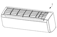
- the indoor unit 1 is in the form of a wall, and sucks in room air from above and blows out air-conditioned air from below to the room.
- the indoor unit 1 is connected to an outdoor unit (not shown), receives supply of refrigerant compressed by the outdoor unit, and adjusts the temperature of the indoor air to a predetermined temperature by the indoor heat exchanger provided inside the indoor unit 1 Do.
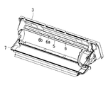
- the interior of the indoor unit 1 is shown in FIG. In the same figure, the indoor heat exchanger and the fan are shown removed.
- the base plate 3 installed on the wall of the room is formed with the water flow path 5 to which the drain water condensed by the indoor heat exchanger is introduced.
- the water flow path 5 is a groove extending in the lateral direction (horizontal direction) of the base plate 3.
- a mounting surface (heat exchanger mounting surface) 6 for supporting the lower surface of the indoor heat exchanger is provided above the water flow path 5.
- the water flow path 5 is formed so as to be bent at a substantially right angle at the left end of the indoor unit 1 and to be directed downward.
- a drain pan 7 is provided below the base plate 3 so as to receive drain water flowing down from the lower end of the water flow path 5. The drain pan 7 temporarily stores drain water and discharges it to the outside of the indoor unit 1.
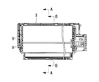
- the entire longitudinal direction D1 is inclined so that the left side is downward, and the near side (the indoor unit front side) is downward in the width direction D2. The whole is inclined. As a result, the drain water is led to the left side and the front side.
- the inclination direction of the water flow passage 5 may be the right side or the rear side (the indoor unit rear side).
- the installation surface 6 has a recess 6 a having a small dimension in the width direction and a projection 6 b having a large dimension in the width direction. That is, on the front side of the installation surface 6, the concave portions 6a and the convex portions 6b are alternately provided in the longitudinal direction.
- an indoor heat exchanger 9 is provided inside the indoor unit 1.
- the indoor heat exchanger 9 shown in the figure is provided on the back side of the indoor unit 1.
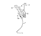
- FIGS. 5A and 5B show a cross-sectional view taken along the line AA of FIG. 4, and FIG. 5B shows a cross-sectional view taken along the line BB shown in FIG.
- a wind shielding member 8 is provided as an insulator between the lower surface of the indoor heat exchanger 9 and the installation surface 6.
- the wind shield member 8 has a shape that substantially matches the shape of the installation surface 6 shown in FIGS. 2 and 3.
- the wind shield member 8 is a flexible member that fills the gap between the lower surface of the indoor heat exchanger 9 and the installation surface 6 and passes through the gap without heat exchange being performed by the indoor heat exchanger 9. It is used to minimize air.
- the width W1 of the shielding member 8 or the mounting surface 6 in FIG. 5A is larger than the width W2 of the shielding member 8 or the mounting surface 6 in FIG. 5B.
- the widths W1 and W2 correspond to the concave portion 6a and the convex portion 6b provided on the installation surface 6 shown in FIGS. That is, in the recess 6a of the installation surface 6, the width (for example, 20 mm to 30 mm) opened in the water flow channel 5 becomes larger as shown in FIG. 5B.
- the width (for example, about 15 mm) opened to the water flow path 5 is small. Therefore, as shown in FIG. 5A, at a position where the width of the installation surface 6 is small and the width opening in the flow passage 5 is large, the operator can easily access from the upper side of the flow passage 5.
- the bottom surface 5a of the water flow channel 5 is provided below the installation surface 6, and both the installation surface 6 and the bottom surface 5a are on the front side of the indoor unit 1 (in FIG. ) Is inclined downward.
- the two indoor heat exchangers 9 are provided in piles in FIG. 5, one heat exchanger may be sufficient.
- the water condensed by the indoor heat exchanger 9 is led to the flow channel 5 and flows into the drain pan 7.
- the water flow channel 5 has a bottom surface 5a which is entirely inclined toward one direction in the longitudinal direction D1 and is entirely inclined toward one direction in the width direction D2. Are collected in one direction in the longitudinal direction D1 and in one direction in the width direction D2. As described above, even if the indoor unit 1 is attached with inclination, the whole of the bottom surface 5a is inclined in the longitudinal direction D1 and the width direction D2, so that the inclination of the bottom surface 5a is always maintained, smoothly Water can be led to the drain pan 7.
- the installation surface 6 has a shape having a recess 6 a whose dimension in the width direction is reduced in the longitudinal direction and a protrusion 6 b whose dimension in the width direction is increased. Thereby, in the recessed part 6a, the space which accesses the bottom face 5a can be ensured larger than the convex part 6b. Thereby, when attaching the wind shielding member 8 provided in the installation surface 6, it can access easily.
- indoor unit base plate 5 water flow channel 5a bottom surface 6 installation surface (heat exchanger installation surface) 7 drain pan 8 wind shield member 9 indoor heat exchanger (heat exchanger)
Landscapes
- Engineering & Computer Science (AREA)
- Chemical & Material Sciences (AREA)
- Combustion & Propulsion (AREA)
- Mechanical Engineering (AREA)
- General Engineering & Computer Science (AREA)
- Physics & Mathematics (AREA)
- Thermal Sciences (AREA)
- Devices For Blowing Cold Air, Devices For Blowing Warm Air, And Means For Preventing Water Condensation In Air Conditioning Units (AREA)
Abstract
Description
すなわち、本発明にの一態様に係る空気調和装置の室内機は、熱交換器から滴下する水を受ける流水路と、該流水路から導かれた水を受けるドレンパンと、を備えている空気調和装置の室内機であって、前記流水路は、長手方向の一方向に向かって全体が傾斜するとともに、該長手方向に直交する幅方向の一方向に向かって全体が傾斜する底面を有している。
図1には、空気調和装置の室内機1の外観が示されている。室内機1は、壁掛形とされており、上方から室内空気を吸い込み、下方から室内へと空調後の空気を吹き出す。室内機1は、図示しない室外機と接続されており、室外機にて圧縮された冷媒の供給を受け、室内機1の内部に設けられた室内熱交換器によって室内の空気を所定温度に調整する。
図5A及び図5Bに示されているように、室内熱交換器9の下面と設置面6との間には、インシュレータとして遮風部材8が設けられている。遮風部材8は、図2及び図3に示した設置面6の形状に略一致させた形状とされている。遮風部材8は、室内熱交換器9の下面と設置面6との間の隙間を埋める可撓性を有する部材であり、室内熱交換器9によって熱交換が行われないで隙間を通過する空気を極小化するために用いられる。
なお、図5において室内熱交換器9が2つ重ねて設けられているが、1つの熱交換器であっても良い。
室内熱交換器9で凝縮した水は流水路5へと導かれドレンパン7へと流れ込む。流水路5には、長手方向D1の一方向に向かって全体が傾斜するとともに、幅方向D2の一方向に向かって全体が傾斜する底面5aを有しているので、流水路5に流れ込んだ水は、長手方向D1に一方向に集められるとともに幅方向D2の一方向に集められる。このように、室内機1が傾斜されて取り付けられても、底面5aの全体が長手方向D1及び幅方向D2に傾斜されているので、底面5aの傾斜が常に維持されることになり、円滑に水をドレンパン7へと導くことができる。
3 ベースプレート
5 流水路
5a 底面
6 設置面(熱交換器設置面)
7 ドレンパン
8 遮風部材
9 室内熱交換器(熱交換器)
Claims (3)
- 熱交換器から滴下する水を受ける流水路と、
該流水路から導かれた水を受けるドレンパンと、
を備えている空気調和装置の室内機であって、
前記流水路は、長手方向の一方向に向かって全体が傾斜するとともに、該長手方向に直交する幅方向の一方向に向かって全体が傾斜する底面を有している空気調和装置の室内機。 - 前記底面は、前記熱交換器の下端が設置された熱交換器設置面よりも下方に位置している請求項1に記載の空気調和装置の室内機。
- 前記熱交換器設置面は、前記長手方向において、前記幅方向の寸法が小さくなる凹部と該寸法が大きくなる凸部とを有し、
前記熱交換器設置面と前記熱交換器の下面との間には、遮風部材が設けられている請求項2に記載の空気調和装置の室内機。
Priority Applications (2)
| Application Number | Priority Date | Filing Date | Title |
|---|---|---|---|
| AU2018245359A AU2018245359B2 (en) | 2017-03-31 | 2018-03-07 | Indoor unit for air conditioning device |
| EP18776766.0A EP3527907A4 (en) | 2017-03-31 | 2018-03-07 | INDOOR UNIT FOR AIR-CONDITIONING DEVICE |
Applications Claiming Priority (2)
| Application Number | Priority Date | Filing Date | Title |
|---|---|---|---|
| JP2017-070984 | 2017-03-31 | ||
| JP2017070984A JP6847739B2 (ja) | 2017-03-31 | 2017-03-31 | 空気調和装置の室内機 |
Publications (1)
| Publication Number | Publication Date |
|---|---|
| WO2018180321A1 true WO2018180321A1 (ja) | 2018-10-04 |
Family
ID=63675319
Family Applications (1)
| Application Number | Title | Priority Date | Filing Date |
|---|---|---|---|
| PCT/JP2018/008862 WO2018180321A1 (ja) | 2017-03-31 | 2018-03-07 | 空気調和装置の室内機 |
Country Status (4)
| Country | Link |
|---|---|
| EP (1) | EP3527907A4 (ja) |
| JP (1) | JP6847739B2 (ja) |
| AU (1) | AU2018245359B2 (ja) |
| WO (1) | WO2018180321A1 (ja) |
Citations (4)
| Publication number | Priority date | Publication date | Assignee | Title |
|---|---|---|---|---|
| JPH06257778A (ja) * | 1993-03-01 | 1994-09-16 | Daikin Ind Ltd | 空気調和機のドレン構造 |
| JP2010249466A (ja) * | 2009-04-17 | 2010-11-04 | Daikin Ind Ltd | 空気調和装置の室内機 |
| JP2015102257A (ja) | 2013-11-22 | 2015-06-04 | ダイキン工業株式会社 | 空気調和機 |
| WO2015136711A1 (ja) | 2014-03-14 | 2015-09-17 | 三菱電機株式会社 | 空気調和機の室内機 |
Family Cites Families (2)
| Publication number | Priority date | Publication date | Assignee | Title |
|---|---|---|---|---|
| JP2011220558A (ja) * | 2010-04-06 | 2011-11-04 | Daikin Industries Ltd | 空気調和装置 |
| JP5606419B2 (ja) * | 2011-09-30 | 2014-10-15 | 三菱電機株式会社 | 空気調和機 |
-
2017
- 2017-03-31 JP JP2017070984A patent/JP6847739B2/ja active Active
-
2018
- 2018-03-07 WO PCT/JP2018/008862 patent/WO2018180321A1/ja unknown
- 2018-03-07 EP EP18776766.0A patent/EP3527907A4/en not_active Withdrawn
- 2018-03-07 AU AU2018245359A patent/AU2018245359B2/en active Active
Patent Citations (4)
| Publication number | Priority date | Publication date | Assignee | Title |
|---|---|---|---|---|
| JPH06257778A (ja) * | 1993-03-01 | 1994-09-16 | Daikin Ind Ltd | 空気調和機のドレン構造 |
| JP2010249466A (ja) * | 2009-04-17 | 2010-11-04 | Daikin Ind Ltd | 空気調和装置の室内機 |
| JP2015102257A (ja) | 2013-11-22 | 2015-06-04 | ダイキン工業株式会社 | 空気調和機 |
| WO2015136711A1 (ja) | 2014-03-14 | 2015-09-17 | 三菱電機株式会社 | 空気調和機の室内機 |
Non-Patent Citations (1)
| Title |
|---|
| See also references of EP3527907A4 |
Also Published As
| Publication number | Publication date |
|---|---|
| JP6847739B2 (ja) | 2021-03-24 |
| EP3527907A1 (en) | 2019-08-21 |
| AU2018245359A1 (en) | 2019-05-23 |
| AU2018245359B2 (en) | 2020-04-30 |
| JP2018173214A (ja) | 2018-11-08 |
| EP3527907A4 (en) | 2019-10-23 |
Similar Documents
| Publication | Publication Date | Title |
|---|---|---|
| EP1416230B1 (en) | Outdoor unit of air conditioner | |
| JP4544364B1 (ja) | 空気調和装置 | |
| EP2933574B1 (en) | Indoor unit of air conditioner | |
| US9903600B2 (en) | Wind direction adjusting device of air-conditioning apparatus and air-conditioning apparatus | |
| JP2014119130A (ja) | 空気調和機の室内機 | |
| JP2009063186A (ja) | 風向ガイドユニット、および、空気調和装置の室外ユニット | |
| US10126013B2 (en) | Heat exchange unit and air-conditioning apparatus | |
| JP6207479B2 (ja) | 空気調和機の室内機、及び、空気調和機の室内機の製造方法 | |
| WO2018180321A1 (ja) | 空気調和装置の室内機 | |
| JP6639159B2 (ja) | 空気調和装置 | |
| JP2008224083A (ja) | 空気調和機 | |
| JP2011089678A (ja) | 分離型空気調和機の室内ユニットの据付装置 | |
| JP2017172935A (ja) | 空気調和機 | |
| JP2019178825A (ja) | 天井埋込型空気調和機 | |
| JP2000356381A (ja) | 熱交換形換気扇 | |
| JP4081681B2 (ja) | 室内機本体及び空気調和機 | |
| JPH1068534A (ja) | 空気調和機 | |
| JP2018091564A (ja) | 空気調和機の室内機 | |
| WO2018198584A1 (ja) | 空気調和装置の室内機 | |
| WO2017022072A1 (ja) | 空調用室内機 | |
| KR100576132B1 (ko) | 공기조화기의 실내기 | |
| JP2007163019A (ja) | 空気調和機の室内機 | |
| JP2004177048A (ja) | 空気調和機の室内機 | |
| JPH0926154A (ja) | 空気調和機 | |
| JP5786850B2 (ja) | 天井設置型室内機 |
Legal Events
| Date | Code | Title | Description |
|---|---|---|---|
| 121 | Ep: the epo has been informed by wipo that ep was designated in this application |
Ref document number: 18776766 Country of ref document: EP Kind code of ref document: A1 |
|
| ENP | Entry into the national phase |
Ref document number: 2018245359 Country of ref document: AU Date of ref document: 20180307 Kind code of ref document: A |
|
| ENP | Entry into the national phase |
Ref document number: 2018776766 Country of ref document: EP Effective date: 20190517 |
|
| NENP | Non-entry into the national phase |
Ref country code: DE |