WO2018180295A1 - 雌型コネクタ、コネクタ対、雌型コネクタの製造方法 - Google Patents
雌型コネクタ、コネクタ対、雌型コネクタの製造方法 Download PDFInfo
- Publication number
- WO2018180295A1 WO2018180295A1 PCT/JP2018/008708 JP2018008708W WO2018180295A1 WO 2018180295 A1 WO2018180295 A1 WO 2018180295A1 JP 2018008708 W JP2018008708 W JP 2018008708W WO 2018180295 A1 WO2018180295 A1 WO 2018180295A1
- Authority
- WO
- WIPO (PCT)
- Prior art keywords
- female
- terminal
- male
- connector
- housing
- Prior art date
- Legal status (The legal status is an assumption and is not a legal conclusion. Google has not performed a legal analysis and makes no representation as to the accuracy of the status listed.)
- Ceased
Links
Images

Classifications
-
- H—ELECTRICITY
- H01—ELECTRIC ELEMENTS
- H01R—ELECTRICALLY-CONDUCTIVE CONNECTIONS; STRUCTURAL ASSOCIATIONS OF A PLURALITY OF MUTUALLY-INSULATED ELECTRICAL CONNECTING ELEMENTS; COUPLING DEVICES; CURRENT COLLECTORS
- H01R13/00—Details of coupling devices of the kinds covered by groups H01R12/70 or H01R24/00 - H01R33/00
- H01R13/02—Contact members
- H01R13/04—Pins or blades for co-operation with sockets
-
- H—ELECTRICITY
- H01—ELECTRIC ELEMENTS
- H01R—ELECTRICALLY-CONDUCTIVE CONNECTIONS; STRUCTURAL ASSOCIATIONS OF A PLURALITY OF MUTUALLY-INSULATED ELECTRICAL CONNECTING ELEMENTS; COUPLING DEVICES; CURRENT COLLECTORS
- H01R13/00—Details of coupling devices of the kinds covered by groups H01R12/70 or H01R24/00 - H01R33/00
- H01R13/02—Contact members
- H01R13/10—Sockets for co-operation with pins or blades
- H01R13/11—Resilient sockets
-
- H—ELECTRICITY
- H01—ELECTRIC ELEMENTS
- H01R—ELECTRICALLY-CONDUCTIVE CONNECTIONS; STRUCTURAL ASSOCIATIONS OF A PLURALITY OF MUTUALLY-INSULATED ELECTRICAL CONNECTING ELEMENTS; COUPLING DEVICES; CURRENT COLLECTORS
- H01R13/00—Details of coupling devices of the kinds covered by groups H01R12/70 or H01R24/00 - H01R33/00
- H01R13/46—Bases; Cases
- H01R13/50—Bases; Cases formed as an integral body
-
- H—ELECTRICITY
- H01—ELECTRIC ELEMENTS
- H01R—ELECTRICALLY-CONDUCTIVE CONNECTIONS; STRUCTURAL ASSOCIATIONS OF A PLURALITY OF MUTUALLY-INSULATED ELECTRICAL CONNECTING ELEMENTS; COUPLING DEVICES; CURRENT COLLECTORS
- H01R31/00—Coupling parts supported only by co-operation with counterpart
- H01R31/06—Intermediate parts for linking two coupling parts, e.g. adapter
-
- H—ELECTRICITY
- H01—ELECTRIC ELEMENTS
- H01R—ELECTRICALLY-CONDUCTIVE CONNECTIONS; STRUCTURAL ASSOCIATIONS OF A PLURALITY OF MUTUALLY-INSULATED ELECTRICAL CONNECTING ELEMENTS; COUPLING DEVICES; CURRENT COLLECTORS
- H01R43/00—Apparatus or processes specially adapted for manufacturing, assembling, maintaining, or repairing of line connectors or current collectors or for joining electric conductors
-
- H—ELECTRICITY
- H01—ELECTRIC ELEMENTS
- H01R—ELECTRICALLY-CONDUCTIVE CONNECTIONS; STRUCTURAL ASSOCIATIONS OF A PLURALITY OF MUTUALLY-INSULATED ELECTRICAL CONNECTING ELEMENTS; COUPLING DEVICES; CURRENT COLLECTORS
- H01R43/00—Apparatus or processes specially adapted for manufacturing, assembling, maintaining, or repairing of line connectors or current collectors or for joining electric conductors
- H01R43/20—Apparatus or processes specially adapted for manufacturing, assembling, maintaining, or repairing of line connectors or current collectors or for joining electric conductors for assembling or disassembling contact members with insulating base, case or sleeve
- H01R43/24—Assembling by moulding on contact members
Definitions
- the present invention relates to a female connector, a connector pair, and a method for manufacturing a female connector, and more particularly, a female connector having a female terminal and a housing, and a connector comprising such a female connector and a male connector.
- the present invention relates to a pair and a method of manufacturing such a female connector.
- a fitting connection between a female connector having a female terminal and a male connector having a male terminal is often used.
- the female terminal accommodates a male terminal having a tab-like shape, a bar-like shape, etc., and forms a conduction path with the male-type terminal.
- an elastic contact piece utilizing a leaf spring structure or the like is formed as an electrical contact inside a conventional female terminal. The elastic contact piece elastically presses the male terminal toward another part of the female terminal, thereby maintaining the fitting structure and conduction between the male terminal and the female terminal.
- a spring structure such as an elastic contact piece
- a fitting structure and conduction between the female terminal and the male terminal there is a portion using a spring structure, such as an elastic contact piece, in order to maintain a fitting structure and conduction between the female terminal and the male terminal.
- a structure has a complicated shape, and a complicated process such as bending is often required for production. Then, the material cost and processing cost of a female connector will become large. Moreover, such a shape becomes a factor which restricts miniaturization of a female connector.
- An object of the present invention is to provide a female connector having a simple shape and manufacturing process, a connector pair provided with such a female connector, and a method for manufacturing such a female connector.
- a female connector according to the present invention has a female terminal made of a hollow tubular metal material and a female housing that holds the female terminal.
- the female housing may be made of a block-shaped polymer material that embeds and fixes the female terminal.
- the female connector may include a plurality of female terminals, and the plurality of female terminals may be fixed to a common female housing with axes parallel to each other.
- the female terminal is preferably made of stainless steel.
- the connector pair according to the present invention includes the female connector as described above and a male connector, and the male connector holds the male terminal made of a rod-shaped metal material, the male terminal, A male housing that can be fitted with a female housing, and the male terminal is placed inside a hollow tube structure of the female terminal in a state where the male housing and the female housing are fitted together. Is inserted, and a conduction path is formed between the female terminal and the male terminal.
- the male terminal has a portion whose dimension in one direction intersecting the longitudinal direction is larger than the inner dimension of the hollow tube structure of the female terminal.
- a method for manufacturing a female connector according to the present invention is a method for manufacturing a female connector as described above, wherein a hollow tube made of a long metal material having a length equal to or longer than two female terminals is provided.
- the female connector according to the invention includes a hollow tubular female terminal.
- a rod-shaped male terminal By inserting a rod-shaped male terminal into the hollow tube structure and bringing it into contact with the inner wall surface of the hollow tube structure, electrical connection can be obtained with the male terminal. Since the female terminal has a simple hollow tube structure, the structure and manufacturing process of the entire female connector can be simplified. As a result, the entire female connector including the female terminals can be downsized.
- the female housing is made of a block-shaped polymer material that embeds and fixes the female terminal
- the female terminal is integrally held by the female housing. It is not necessary to provide a structure for mechanically holding the female terminal. Therefore, the entire female connector has a simple structure and can be easily downsized.
- a polymer material having fluidity is used for the female terminal. It only has to be introduced to the surroundings and solidified, and there is no need for mechanical assembly. The error related to the placement of the female terminal tends to be large in the mechanical assembly process, but the placement error of the female terminal can be kept small by eliminating the mechanical assembly. In particular, when a large number of female terminals are fixed by a common female housing, the effect of suppressing the placement error is increased.
- the female connector has a plurality of female terminals, and the plurality of female terminals are fixed to a common female housing with their axes parallel to each other, the female terminals are simple.
- a large number of female terminals can be arranged at a narrow interval, and the entire female connector can be easily miniaturized.
- the female terminal is made of stainless steel
- stainless steel is a material having high strength and bending elasticity
- a high contact load is applied from the female terminal to the male terminal, so that the physical holding of the male terminal by the female terminal and the conduction between the two terminals can be firmly performed.
- stainless steel is hard to receive corrosion, durability of a female connector can be improved.
- the female terminal has a simple hollow tube structure, thereby simplifying the structure and manufacturing process of the female connector, but the male terminal is simple.
- the structure and manufacturing process of the male connector can be simplified. Therefore, the structure and the manufacturing process can be simplified and further downsized as the whole connector pair.
- the male terminal when the male terminal has a portion where the dimension in one direction intersecting the longitudinal direction is larger than the inner dimension of the hollow tube structure of the female terminal, the male terminal is inside the hollow tube structure of the female terminal.
- the female terminal When the rod-shaped male terminal is inserted, the female terminal is deformed to be expanded outward along the direction in which the dimension of the male terminal is increased. Then, a pressing force is applied from the part which received the deformation
- This pressing force functions as a contact load between the female terminal and the male terminal, and the physical holding state of the male terminal in the hollow portion of the female terminal and the conduction between both terminals are maintained. It becomes easy.
- a polymer material that has a fluid state after a long hollow tube serving as a female terminal is disposed at a predetermined position using a mold or the like. Is introduced into the periphery and solidified to produce a raw material body. A plurality of female connectors can be obtained at a time simply by dividing the raw material body. Thus, a large number of female connectors can be manufactured by a simple process.
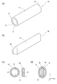
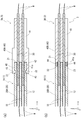
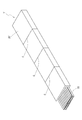
- FIG. 1 It is a perspective view which shows the female connector concerning one Embodiment of this invention. It is a figure explaining the female terminal and male terminal which are included in the connector pair concerning one embodiment of the present invention, and (a) and (b) are perspective views of a female terminal and a male terminal, respectively.
- C) And (d) is sectional drawing of a female terminal and a male terminal, and has shown the state before a connection and after a connection, respectively. It is a figure which shows the connector pair of the state which fitted and connected the female connector and the male connector, (a) And (b) has shown the different form. It is a perspective view explaining the manufacturing method of the female connector concerning one Embodiment of this invention.
- FIG. 1 shows a configuration of a female connector 1 according to an embodiment of the present invention.
- the female connector 1 has a plurality of female terminals 10 and a female housing 20.
- the female terminal 10 is made of a metal material and has a hollow tube shape as shown in FIG.
- the female terminal 10 has the shape of a linear hollow cylindrical tube having substantially the same circular cross section from one end 14 to the other end 15 along the longitudinal axis.
- the plurality of female terminals 10 are fixed by a common female housing 20 with their longitudinal axes substantially parallel.
- the female terminals 10 are arranged in two stages in a state in which many female terminals 10 are arranged horizontally at substantially equal intervals. The positions of both ends 14 and 15 of each female terminal 10 are aligned.
- the female housing 20 is made of a block-like insulating polymer material. That is, the female housing 20 is formed of a solid body filled with a polymer material except for the space occupied by the female terminal 10, and preferably, from one end to the other end along the longitudinal axis of the female terminal 10. It consists of a solid columnar body having substantially the same cross-sectional shape.
- the female housing 20 is in close contact with the substantially entire region of the outer peripheral surface 11 of each female terminal 10 and embeds the female terminal 10 to fix the female terminal 10 at a predetermined position.
- An electric wire W is connected to one end 14 of the female terminal 10 (see FIG. 3).
- the connection of the electric wire W to the female terminal 10 can be performed by welding, joining via solder or a conductive adhesive, or the like.
- the other male terminal 30 can be connected from the other end 15 of the female terminal 10.
- the male terminal 30 is inserted into the hollow portion 12 of each female terminal 10.
- the female terminal 10 holds the male terminal 30 in the hollow portion 12 and forms a conduction path with the male terminal 30 (see FIG. 2D).
- the metal material constituting the female terminal 10 is not particularly specified, and examples thereof include copper, aluminum, titanium, iron, and alloys containing them as the main components. As will be described later, when the holding state and conduction of the male terminal 30 are maintained by the restoring force generated by the deformation of the female terminal, a large contact load is applied from the female terminal 10 to the male terminal 30. As given, it is preferable to use a metal material having high strength and bending elasticity as the material constituting the female terminal 10. An example of such a metal material is stainless steel. Especially, it is preferable to use stainless steel excellent in bending elasticity called spring steel, such as SUS 301CSP and SUS 304CSP.
- Stainless steel is also suitable in that it is less susceptible to corrosion and can enhance the durability of the female terminal 10 in a corrosive environment.
- a metal layer such as a tin plating layer may be appropriately provided on the inner wall surface 13 of the female terminal 10.
- the outer peripheral surface 11 of the female terminal 10 may be appropriately subjected to surface treatment for the purpose of increasing the affinity with the polymer material constituting the female housing 20.
- the polymer material constituting the female housing 20 is not particularly specified, and the same material as conventionally used for constructing the connector housing can be applied. Examples thereof include resin materials such as olefin resins and ester resins, elastomer materials, and the like. As will be described later, for convenience in manufacturing the female connector 1 by insert molding, the polymer material constituting the female housing 20 is preferably thermoplastic. In addition, it is preferable to use a polymer material having heat resistance that does not change the holding state of the female terminal 10 by the female housing 20 even when the female housing 20 is heated by energization of the female terminal 10 or the like. . Further, when the female terminal 10 is deformed by the insertion of the male terminal 30, it is preferable that the polymer material has an elasticity that allows the female housing 20 to follow and reversibly deform.
- the female terminal 10 has a hollow tube shape, and has a portion having a complicated shape such as an elastic contact piece provided on a conventional general female terminal. Not done.
- the female terminal 10 has a simple configuration, and accordingly, the female connector 1 as a whole is simply constructed by fixing the tubular female terminal 10 with the block-shaped female connector 20. It is possible to adopt a simple configuration. Further, since the female terminal 10 can be manufactured by cutting the long raw material hollow tube 10 ′ as in the manufacturing method described later, the female connector 1 including the female terminal 10 can be manufactured by a simple method. Can be manufactured. Since the female terminals 10 can be arranged close to each other, the female connector 1 can be easily downsized.
- the female terminal 10 is not particularly limited to the linear cylindrical shape as described above as long as it has a hollow tube shape.
- the female terminal 10 has a bent structure in the middle part, and the cross-sectional size and shape are halfway. It is also possible to consider a form that changes. However, when it consists of the linear cylindrical body which has the substantially same cross-sectional shape from the one end 14 to the other end 15, it becomes especially excellent in the shape, the simplicity of a manufacturing process, and the possibility of size reduction.
- the specific shape of the female housing 20 is not particularly limited as long as the female terminal 10 can be held. However, as described above, a large number of female terminals 10 can be brought close to each other by forming a block shape. Even in the case of the arrangement, it is easy to achieve the high-precision holding of the relative arrangement and the maintenance of the mutual insulation, which is effective in reducing the size of the female connector 1 as a whole. Further, a female terminal 10 or a long raw material hollow tube 10 ′ as a raw material thereof is disposed at a predetermined position using a mold or the like, and a polymer material having a high fluidity is used as the female terminal.
- the female housing 20 By introducing and solidifying around the terminal 10 or the raw material hollow tube 10 ′, the female housing 20 can be easily formed, and the arrangement of the female terminals 10 in the female housing 20 can be fixed. In this way, the production of the female housing 20 and the fixing of the female terminal 10 to the female housing 20 can be performed simultaneously. Further, when the female terminal 10 is fixed to the female housing 20, there is no need to intervene a mechanical assembly process, so that an error in the arrangement of the female terminal 10 that tends to be large during mechanical assembly, particularly An error in pitch between the plurality of female terminals 10 can be reduced.
- the female housing 20 is formed of a columnar body having substantially the same cross section along the longitudinal axis of the female terminal 10, the entire female connector 1 including the female housing 20 is disposed as will be described later. It can be easily manufactured by cutting the elongated raw material 1 '.
- the connector pair according to the embodiment of the present invention includes a set of the female connector 1 and the male connector 3 according to the embodiment of the present invention described above.
- the male connector 3 constituting the connector pair has a male terminal 30 made of a rod-shaped metal material and a male housing 40 made of a polymer material that holds the male terminal 30.
- a male terminal 30 made of a rod-shaped metal material
- a male housing 40 made of a polymer material that holds the male terminal 30.
- specific materials constituting the male terminal 30 and the male housing 40 the same materials as those described above as the material constituting the female terminal 10 and the female housing 20 can be applied.
- the male housing 40 has a shape that can be fitted to the female housing 20 of the female connector 1.
- the number and arrangement of the male terminals 30 in the male connector 3 are such that the male terminals 30 are inserted into the hollow portions 12 of the female terminals 10 when the male housing 40 is fitted to the female housing 20. It has become.
- the male terminal 30 has a linear rod-like shape. From the viewpoint of material strength, the male terminal 30 is preferably solid.
- the male terminal 30 has a dimension L3 in at least one direction (the major axis direction) intersecting the longitudinal axis in at least a part in the longitudinal direction, here, the entire shaft portion 31 which is the main body portion of the male terminal 30. However, it is larger than the inner dimension L1 of the hollow portion 12 of the female terminal 10. In the form shown in FIGS.
- the cross section of the shaft portion 31 has a substantially oval shape (a shape in which a semicircle is joined to both ends of the long side of the rectangle),
- the length L3 is larger than the inner diameter L1 of the hollow portion 12 of the female terminal 10.
- the cross-sectional shape of the shaft portion 31 of the male terminal 30 is not limited to an oval shape, but preferably has an elongated cross-sectional shape in which a dimension in a specific direction is increased so that the female terminal 10 is easily deformed upon insertion.
- a rectangle or an ellipse can be exemplified. Among these, from the viewpoint of securing a large contact area with the female terminal 10, an oval shape or an elliptical shape having curved outwardly protruding edges on both sides in the major axis direction of the cross section is preferable.
- a tapered portion 32 is formed integrally with the shaft portion 31 on the tip end side of the shaft portion 31.
- the taper portion 32 has a tapered shape in which the cross-sectional dimension gradually decreases toward the tip of the male terminal 30.
- the tip of the taper portion 32 is formed with a size smaller than the inner diameter L1 of the hollow portion 12 of the female terminal 10, and is disposed in the hollow portion 12 of the female terminal 10 without deforming the female terminal 10. It is possible.
- the male terminal 30 having the shape as described above is inserted into the hollow portion 12 of the female terminal 10.
- the longitudinal axis of the male terminal 30 and the female terminal 10 is aligned.
- the along direction is the x direction.
- the major axis direction (the direction of the length L3) in the cross section of the shaft portion 31 of the male terminal 30 is the z direction.
- a direction orthogonal to the x direction and the z direction is taken as a y direction.
- the male terminal 30 and the female terminal 10 are parallel to each other in the longitudinal direction (x direction), and the male terminal 30 is connected to the tapered portion 32.
- the tapered portion 32 of the male terminal 30 a portion where the dimension in the z direction exceeds the inner diameter L ⁇ b> 1 of the hollow portion 12 of the female terminal 10 comes into contact with the inner wall surface 13 of the female terminal 10. Then, the female terminal 10 starts to be deformed so as to be expanded outward in the z direction.
- the male terminal 30 When the male terminal 30 is further advanced and the shaft portion 31 of the male terminal 30 comes into contact with the inner wall surface 13 of the female terminal 10, the deformation amount of the female terminal 10 is further increased. As shown in FIG. 3, the male terminal 30 is hollow in the female terminal 10 to a predetermined position in the x direction defined by the contact between the front end surface 21 of the female housing 20 and the front end surface 41 a of the male housing 40. Inserted into the section 12.
- the female terminal 10 is in contact with the outer peripheral surface of the shaft portion 31 of the male terminal 30 at both ends in the z direction of the inner wall surface 13 in a state where the female terminal 10 is deformed into an oval cross section toward the outside in the z direction.
- the inner dimension in the z direction of the hollow portion 12 of the female terminal 10 is substantially equal to the dimension L3 in the major axis direction of the shaft portion 31 of the male terminal 30.
- the male terminal 30 is not limited to the one having the shaft portion 31 in which the dimension L3 in one direction is larger than the inner dimension L1 of the hollow portion 12 of the female terminal 10, and is inserted into the hollow portion 12 of the female terminal 10.
- any material can be used as long as it can contact the inner wall surface 13 of the female terminal 10 and obtain electrical continuity with the female terminal 10.
- the female terminal 10 can be deformed by insertion of the male terminal 30 and a contact load can be generated by the deformation, the physical maintenance of the inserted state and the maintenance of conduction are maintained. A high effect can be obtained.
- a male type It can be considered that the terminal can be deformed in a predetermined direction, and the male terminal is elastically pressed against the inner wall surface 13 of the female terminal 10 by utilizing the deformation of the male terminal.
- the state in which the male terminal 30 is inserted into the hollow portion 12 of the female terminal 10 can be physically maintained by the contact load generated by the deformation of the female terminal 10.
- a holding member for holding the fitted state between the female housing 20 and the male housing 40.
- FIGS. 3A and 3B Two examples of the configuration of the connector pair having such a holding member are shown in FIGS. 3A and 3B, for the sake of easy viewing, a space is provided in the part that is actually in contact with the display.
- a pair of arm portions 42, 42 are provided on the distal end side ( ⁇ x side) of a block portion 41 having a rectangular parallelepiped block shape for holding the male terminal 30. Is provided.
- the arm portions 42 and 42 are formed integrally with the block portion 41 by the same polymer material as that of the block portion 41.
- a pair of cantilever-like arm portions 42, 42 are provided so as to face each other and protrude forward ( ⁇ x direction) from the front end surface 41 a of the block portion 41.
- the positions of the pair of arm portions 42, 42 are set so that the female housing 20A can be sandwiched therebetween.
- Engagement projections 43 and 43 are provided at the tips of the arm portions 42 and 42, respectively, protruding in opposite directions ( ⁇ z directions).
- a pair of engaging recesses 22 and 22 are provided on two opposing side surfaces.
- the engaging recesses 22 and 22 are provided in the arm portions 42 and 42 of the male housing 40A in a state where the distal end surface 21 of the female housing 20A is in contact with the distal end surface 41a of the block portion 41 of the male housing 40A.
- the engaging protrusions 43 and 43 are formed in positions and shapes that can be inserted.
- the pair of arms of the male housing 40A is inserted while inserting the male terminal 30 into the hollow portion 12 of the female terminal 10 along the x direction.
- the female housing 20A is sandwiched between the pair of arm portions 42 and 42 so as to elastically push the portions 42 and 42 outward in the z direction. Then, at the position where the distal end surface 21 of the female housing 20A abuts on the distal end surface 41a of the block portion 41 of the male housing 40A, the engaging convex portions 43, 43 provided on the arm portions 42, 42 are the female housing. It fits into engaging recesses 22 and 22 provided in 20A.
- the engagement state of the male housing 40A and the female housing 20A is maintained by the engagement of the engagement convex portions 43, 43 and the engagement concave portions 22, 22. That is, the male housing 40A and the female type in both the direction (x direction) along the longitudinal axis of the female terminal 10 and the male terminal 30 and the direction (y direction and z direction) intersecting the longitudinal axis. A relative shift between the housings 20A is suppressed.
- engagement protrusions 44, 44 are provided on the front end surface 41a of the block portion 41 having a rectangular parallelepiped block shape.
- the engagement protrusions 44 and 44 are formed integrally with the block portion 41 by the same polymer material as that of the block portion 41.
- the engagement protrusions 44 and 44 are provided so as to protrude forward ( ⁇ x direction) from the front end surface 41 a of the block portion 41 substantially parallel to the longitudinal axis of the male terminal 30.
- engagement holes 23 and 23 are provided in the tip surface 21 as a depressed structure along the x direction.
- the engagement holes 23, 23 are formed on the distal end surface 41a of the block portion 41 of the male housing 40B in a state where the distal end surface 21 of the female housing 20B is in contact with the distal end surface 41a of the block portion 41 of the male housing 40B.
- the provided engaging projections 44, 44 are formed in positions and shapes that can be fitted.
- the male terminal 30 is inserted into the hollow portion 12 of the female terminal 10 along the x direction so that the distal end surface 21 of the female housing 20B and the male
- the engagement protrusions 44, 44 of the male housing 40B enter the engagement holes 23, 23 of the female housing 20B.
- the engagement state of the male housing 40B and the female housing 20B is maintained by the engagement of the engagement protrusions 44, 44 with the engagement holes 23, 23.
- the relative shift between the male housing 40B and the female housing 20B in the direction (y direction and z direction) intersecting the longitudinal axis of the female terminal 10 and the male terminal 30 is suppressed.
- the female connector 1 has the female terminals 10 having a simple hollow tube structure, so that the entire female connector 1 has a simple structure. It is easy to reduce the size.
- the male terminal 30 connected to the hollow tubular female terminal 10 can also have a simple rod-like structure.
- the entire male connector 3 can also have a simple configuration in which the rod-shaped male terminal 30 is held by the block portion 41 of the male housing 40.
- the male connector 3 is also easy to downsize.
- the connector pair as a whole has a simple configuration and is suitable for downsizing.
- the female housing 20 is configured in a block shape, and the male housing 40 also mainly includes the block portion 41, if both the housings 20 and 40 are composed of only these block-shaped portions, the female connector 1 and the male connector are formed.
- the mechanism that holds the fitting structure between the connectors 3 is only the contact load applied from the deformed female terminal 10 to the male terminal 30, and the fitting state may not be sufficiently maintained.
- the male housing 40 and the female housing 20 are provided with a set of engaging convex portions 43 and 43 and engaging concave portions 22 and 22,
- a holding member such as a set of the mating protrusions 44 and 44 and the engagement holes 23 and 23, it is easy to maintain the fitting state between the female connector 1 and the male connector 3.
- the engaging structure of these holding members and the structure of inserting the female terminal 10 into the male terminal 30 are reversibly releasable, and the female connector 1 and the male connector 3 can be connected and disconnected. It can be done repeatedly.
- the holding members such as the set of the engaging projections 43 and 43 and the engaging recesses 22 and 22 and the set of the engaging projections 44 and 44 and the engaging holes 23 and 23 are combined in a plurality of types to form the housing 20. 40 may be provided.
- a long raw material body 1 ′ as shown in FIG. 4 is prepared.
- the raw material body 1 ′ is a raw material hollow tube made of a long metal material having a length of two or more female terminals (10) in the female connector 1 to be manufactured (four or more in FIG. 4). 10 'is embedded and fixed in the raw material polymer part 20' made of a polymer material.
- Such a raw material body 1 ′ can be manufactured by insert molding, for example. That is, a mold corresponding to the shape of the raw material polymer portion 20 ′ is prepared, and the raw material hollow tube 10 ′ is arranged inside the mold so as to correspond to the arrangement of the female terminals 10 in the female connector 1 to be manufactured. Place. Then, a polymer material having a high fluidity such as liquid is introduced into the mold, and the polymer material is disposed on the outer periphery of the raw material hollow tube 10 ′. In this state, the polymer material is solidified. In this way, a long raw material body 1 ′ is obtained. Insert molding can also be performed by a continuous molding method.
- the raw material hollow tube 10 ′ can be manufactured by a method in which a thin metal plate is bent into a cylindrical shape and a joint portion is welded, or by extrusion molding of a metal material.
- the obtained raw material body 1 ′ is divided into a plurality of parts in the axial direction of the raw material hollow tube 10 ′.
- the raw material hollow tube 10 ′ and the raw material polymer part 20 ′ are cut simultaneously at a cutting line C set in accordance with the length dimension of the female connector 1 to be manufactured.
- a cutting line C set in accordance with the length dimension of the female connector 1 to be manufactured.
- the divided body obtained by cutting the raw material body 1 ′ can be used as it is as the female connector 1, but it is added to each of the obtained divided bodies. Work may be done. As the additional machining, end face polishing and chamfering, formation of engagement recesses 22 and 22 or engagement holes 23 and 23 as shown in FIG.
- the male connector 3 constituting the connector pair according to the embodiment of the present invention described above can be manufactured by a similar method. That is, a long raw material body in which a long rod material to be the male terminal 30 is embedded and fixed with a polymer material is prepared, and the raw material body may be divided into a plurality of parts. As shown in FIG. 3, in the case of the male connector 3, unlike the female connector 1, it is necessary to provide the male terminal 30 so as to protrude forward from the front end surface 41 a of the block portion 41 of the male housing 40. Further, it is also required to provide the arm portions 42 and 42 and the engagement protrusions 44 and 44 having the engagement convex portions 43 and 43.
- the polymer material when cutting the raw material body, is not cut into a simple linear shape like the cutting line C, but in a shape that matches the structure to be formed. Just cut it.
- the structure can be formed by removing the polymer material into a predetermined shape in an additional process.
- a method is conceivable in which the arm portions 42 and 42 and the engaging projections 44 and 44 are manufactured separately and joined to the block portion 41 obtained by cutting by fusion, adhesion, or the like.
Landscapes
- Engineering & Computer Science (AREA)
- Manufacturing & Machinery (AREA)
- Connector Housings Or Holding Contact Members (AREA)
Abstract
中空管状の金属材料よりなる雌型端子(10)と、雌型端子(10)を保持する雌型ハウジング(20)と、を有する雌型コネクタ(1)とする。そのような雌型コネクタ(1)と雄型コネクタ(3)とよりなるコネクタ対とする。雄型コネクタ(3)は、棒状の金属材料よりなる雄型端子(30)と、雄型端子を保持し、雌型ハウジング20と嵌合可能な雄型ハウジング(40)と、を有し、雄型ハウジング(40)と雌型ハウジング(20)を嵌合させた状態において、雌型端子(10)の中空管構造の内部に雄型端子(30)が挿入され、雌型端子(10)と雄型端子(30)の間に導通経路が形成される。雌型コネクタ(1)の製造は、図示された端子(10)複数個分の長尺状の金属材料よりなる中空管(12)をポリマー材料(20)で包埋して固定した原料体を作製する工程と、原料体を中空管(12)の軸方向に複数に分割する工程と、により行う。
Description
本発明は、雌型コネクタ、コネクタ対、雌型コネクタの製造方法に関し、さらに詳しくは、雌型端子とハウジングとを有する雌型コネクタ、そのような雌型コネクタと雄型コネクタの組よりなるコネクタ対、およびそのような雌型コネクタの製造方法に関するものである。
電気接続の形成に、雌型端子を備える雌型コネクタと、雄型端子を備える雄型コネクタとの嵌合接続が、しばしば用いられる。雌型端子は、タブ状、棒状等の形状を有する雄型端子を収容し、雄型端子との間に導通経路を形成するものであり、特許文献1等に記載されるように、雄型端子の物理的な保持と導通の維持のために、従来一般の雌型端子の内部には、電気接点として、板ばね構造等を利用した弾性接触片が形成されている。弾性接触片によって、雄型端子を雌型端子の別の部位に向かって弾性的に押し付けることにより、雄型端子と雌型端子の間の嵌合構造と導通の維持が図られる。
上記のように、従来一般の雌型コネクタにおいては、雌型端子と雄型端子との間の嵌合構造と導通の維持のために、弾性接触片のように、ばね構造を利用した部位が雌型端子に形成されるが、その種の構造は、複雑な形状を有し、また、作製において、曲げ加工等、煩雑な工程を要することが多い。すると、雌型コネクタの材料コストや加工コストが大きくなってしまう。また、そのような形状が、雌型コネクタの小型化を制限する要因となる。
本発明の課題は、形状および製造工程の簡素な雌型コネクタ、およびそのような雌型コネクタを備えたコネクタ対、さらにそのような雌型コネクタの製造方法を提供することにある。
上記課題を解決するため、本発明にかかる雌型コネクタは、中空管状の金属材料よりなる雌型端子と、前記雌型端子を保持する雌型ハウジングと、を有するものである。
ここで、前記雌型ハウジングは、前記雌型端子を包埋して固定するブロック状のポリマー材料よりなるとよい。また、前記雌型コネクタは、前記雌型端子を複数有し、該複数の雌型端子は、軸を相互に平行にして、共通の前記雌型ハウジングに固定されているとよい。そして、前記雌型端子は、ステンレス鋼よりなるとよい。
本発明にかかるコネクタ対は上記のような雌型コネクタと、雄型コネクタと、よりなり、前記雄型コネクタは、棒状の金属材料よりなる雄型端子と、前記雄型端子を保持し、前記雌型ハウジングと嵌合可能な雄型ハウジングと、を有し、前記雄型ハウジングと前記雌型ハウジングを嵌合させた状態において、前記雌型端子の中空管構造の内部に前記雄型端子が挿入され、前記雌型端子と前記雄型端子の間に導通経路が形成されるものである。
ここで、前記雄型端子は、長手方向に交差する1方向の寸法が前記雌型端子の中空管構造の内寸よりも大きい部位を有するとよい。
本発明にかかる雌型コネクタの製造方法は、上記のような雌型コネクタを製造する方法において、前記雌型端子2個分以上の長さを有する長尺状の金属材料よりなる中空管をポリマー材料で包埋して固定した原料体を作製する工程と、前記原料体を前記中空管の軸方向に複数に分割して、前記雌型コネクタを複数得る工程と、を有するものである。
上記発明にかかる雌型コネクタは、中空管状の雌型端子を備えている。中空管構造の内部に、棒状の雄型端子を挿入し、中空管構造の内壁面と接触させることで、雄型端子との間に導通を得ることができる。雌型端子が、単純な中空管構造を有しているため、雌型コネクタ全体の構造および製造工程を簡素化することができる。その結果、雌型端子を含む雌型コネクタ全体を小型化することも可能となる。
ここで、雌型ハウジングが、雌型端子を包埋して固定するブロック状のポリマー材料よりなる場合には、雌型端子を雌型ハウジングによって一体的に保持することになるので、雌型ハウジングに、雌型端子を機械的に保持するための構造を設ける必要がない。そのため、雌型コネクタ全体を、簡素な構造とし、小型化することが容易となる。また、雌型ハウジングの製造および雌型ハウジングによる雌型端子の固定を行う際に、例えば、金型等に雌型端子を配置した状態で、流動性を有する状態のポリマー材料を雌型端子の周囲に導入し、固化させればよく、機械的な組み立てを行う必要がない。雌型端子の配置にかかる誤差は、機械的組み立ての工程で大きくなりやすいが、機械的組み立てを排除することで、雌型端子の配置誤差を小さく抑えることができる。特に、多数の雌型端子を共通の雌型ハウジングで固定する場合には、配置誤差抑制の効果が大きくなる。
また、雌型コネクタが、雌型端子を複数有し、該複数の雌型端子が、軸を相互に平行にして、共通の雌型ハウジングに固定されている場合には、雌型端子が単純な中空管形状を有していることにより、多数の雌型端子を狭い間隔で配列することができ、雌型コネクタ全体を小型化しやすい。
そして、雌型端子が、ステンレス鋼よりなる場合には、ステンレス鋼は、高い強度と曲げ弾性を備えた材料であるため、雄型端子を雌型端子の中空管構造の内部に挿入した際に、雌型端子から雄型端子に対して高い接触荷重が印加され、雌型端子による雄型端子の物理的な保持と両端子の間の導通の維持を強固に行うことができる。また、ステンレス鋼は、腐食を受けにくいので、雌型コネクタの耐久性を高めることができる。
上記発明にかかるコネクタ対においては、上記のように、雌型端子が単純な中空管構造を有することにより、雌型コネクタの構造と製造工程が簡素なものとなるが、雄型端子が単純な棒状の構造を有することにより、雄型コネクタの構造と製造工程も簡素なものとすることができる。よって、コネクタ対全体として、構造と製造工程の簡素化、さらに小型化を図ることができる。
ここで、雄型端子が、長手方向に交差する1方向の寸法が雌型端子の中空管構造の内寸よりも大きい部位を有する場合には、雌型端子の中空管構造の内部に棒状の雄型端子を挿入した際に、雄型端子の寸法が大きくなっている方向に沿って、雌型端子が外側へと押し広げられる変形を受ける。すると、雌型端子の変形を受けた部位から、接触している雄型端子に向かって、押圧力が印加される。この押圧力が雌型端子と雄型端子の間の接触荷重として機能し、雌型端子の中空部の中における雄型端子の物理的な保持状態と、両端子の間の導通が、維持されやすくなる。
上記発明にかかる雌型コネクタの製造方法においては、金型等を用いて雌型端子となる長尺状の中空管を所定の位置に配置したうえで、流動性を有する状態としたポリマー材料をその周囲に導入し、固化させることで、原料体を製造することができる。そして、その原料体を分割するだけで、複数の雌型コネクタを一度に得ることができる。このように、簡素な工程で多数の雌型コネクタを製造することができる。
以下、図面を用いて本発明の一実施形態にかかる雌型コネクタおよびコネクタ対、そして雌型コネクタの製造方法について、詳細に説明する。
[雌型コネクタの構成]
図1に、本発明の一実施形態にかかる雌型コネクタ1の構成を示す。雌型コネクタ1は、複数の雌型端子10と、雌型ハウジング20と、を有している。
図1に、本発明の一実施形態にかかる雌型コネクタ1の構成を示す。雌型コネクタ1は、複数の雌型端子10と、雌型ハウジング20と、を有している。
雌型端子10は、金属材料よりなっており、図2(a)にも示すように、中空管の形状を有している。ここでは、雌型端子10は、長手方向軸に沿って一端14から他端15まで略同一の円形の断面を備えた直線状の中空円筒管の形状を有している。
複数の雌型端子10は、その長手方向軸を略平行にして、共通の雌型ハウジング20によって固定されている。図1の例では、雌型端子10は、略等間隔に多数が横に並べられた状態で、2段に配列されている。各雌型端子10の両端14,15の位置は揃っている。
雌型ハウジング20は、ブロック状の絶縁性ポリマー材料よりなっている。つまり、雌型ハウジング20は、雌型端子10が占める空間を除いて、ポリマー材料が充填された中実体よりなっており、好ましくは、雌型端子10の長手方向軸に沿って一端から他端まで略同一の断面形状を有する中実状の柱状体よりなっている。雌型ハウジング20は、各雌型端子10の外周面11の略全域に密着しており、雌型端子10を包埋して、雌型端子10を所定の位置に固定している。
雌型端子10の一端14には、電線Wが接続される(図3参照)。雌型端子10への電線Wの接続は、溶接、はんだや導電性接着剤を介した接合等によって行うことができる。一方、雌型端子10の他端15から、相手方の雄型端子30を接続することができる。次にコネクタ対の構造として詳細に説明するように、各雌型端子10の中空部12には、雄型端子30が挿入される。雌型端子10は、その雄型端子30を中空部12の中に保持するとともに、雄型端子30との間に導通経路を形成する(図2(d)参照)。
雌型端子10を構成する金属材料は特に指定されず、銅、アルミニウム、チタン、鉄や、それらを主成分とする合金を例示することができる。後述するように、雌型端子の変形に伴って生じる復元力によって雄型端子30の保持状態と導通の維持を行う場合には、雌型端子10から雄型端子30に対して大きな接触荷重を与えられるように、雌型端子10を構成する材料として、高い強度と曲げ弾性を有する金属材料を用いることが好ましい。そのような金属材料として、ステンレス鋼を挙げることができる。なかでも、SUS 301CSPやSUS 304CSP等、ばね鋼と称される曲げ弾性に優れたステンレス鋼を用いることが好ましい。ステンレス鋼は、腐食を受けにくく、腐食環境における雌型端子10の耐久性を高められるという点でも適している。雌型端子10の内壁面13には、雄型端子30との間の接続信頼性を高めるために、スズめっき層等の金属層を適宜設けてもよい。また、雌型端子10の外周面11には、雌型ハウジング20を構成するポリマー材料との間の親和性を高める等の目的で、適宜表面処理を行ってもよい。
雌型ハウジング20を構成するポリマー材料も特に指定されず、従来一般にコネクタハウジングを構成するのに用いられてきたのと同様の材料を適用することができる。例えば、オレフィン系樹脂やエステル系樹脂等の樹脂材料、エラストマー材料等を挙げることができる。後述するようにインサート成形によって雌型コネクタ1を製造する際の利便性から、雌型ハウジング20を構成するポリマー材料は、熱可塑性のものであることが好ましい。また、雌型端子10への通電等によって雌型ハウジング20が加熱を受けても、雌型ハウジング20による雌型端子10の保持状態が変化しない程度の耐熱性を有するポリマー材料を用いることが好ましい。さらに、雄型端子30の挿入によって雌型端子10が変形した際に、雌型ハウジング20がそれに追随して可逆的に変形できるだけの弾性を、ポリマー材料が有していることが好ましい。
以上のように、本雌型コネクタ1においては、雌型端子10が、中空管形状よりなっており、従来一般の雌型端子に設けられる弾性接触片のような複雑な形状の部位を有していない。このように、雌型端子10が簡素な構成となっており、それに伴って、雌型コネクタ1全体としても、管状の雌型端子10をブロック状の雌型コネクタ20で固定しただけの、簡素な構成とすることが可能となっている。また、後述する製造方法のように、長尺状の原料中空管10’を切断することで雌型端子10を製造できるので、簡素な方法で、雌型端子10を含む雌型コネクタ1を製造することができる。そして、雌型端子10同士を近接して配置することができるので、雌型コネクタ1を小型化しやすい。
雌型端子10は、中空管形状であれば、特に上記のような直線状の円筒形に限られず、例えば、中途部に曲げ構造を有している形態や、断面の寸法や形状が途中で変化する形態も考えうる。しかし、一端14から他端15まで略同一の断面形状を有する直線状の筒状体よりなる場合に、形状や製造工程の簡素性、小型化の可能性において特に優れたものとなる。
雌型ハウジング20の具体的な形状も、雌型端子10を保持できるものであれば、特に限定されないが、上記のように、ブロック状とすることで、多数の雌型端子10を近接して配置する場合にも、その相対配置の高精度な保持と相互間の絶縁の維持を達成しやすく、雌型コネクタ1全体の小型化に効果を有する。また、金型等を用いて雌型端子10またはその原料となる長尺状の原料中空管10’を所定の位置に配置したうえで、流動性の高い状態にしたポリマー材料をそれら雌型端子10または原料中空管10’の周囲に導入し、固化させることで、容易に雌型ハウジング20を形成し、さらに雌型ハウジング20における雌型端子10の配置を固定することができる。このように、雌型ハウジング20の製造と、雌型ハウジング20への雌型端子10の固定を、同時に行うことができる。そして、雌型端子10を雌型ハウジング20に固定する際に、機械的組み立ての工程を介在させなくてもよいので、機械的組み立ての際に大きくなりやすい雌型端子10の配置の誤差、特に複数の雌型端子10の間のピッチの誤差を小さく抑えることができる。さらに、雌型ハウジング20が、雌型端子10の長手方向軸に沿って略同一の断面を有する柱状体よりなる場合には、後述するように、雌型ハウジング20を含む雌型コネクタ1全体を、長尺状の原料体1’の切断によって簡便に製造することができる。
[コネクタ対]
次に、本発明の一実施形態にかかるコネクタ対について説明する。本発明の一実施形態にかかるコネクタ対は、図3に示すように、上記で説明した本発明の一実施形態にかかる雌型コネクタ1と、雄型コネクタ3の組よりなる。
次に、本発明の一実施形態にかかるコネクタ対について説明する。本発明の一実施形態にかかるコネクタ対は、図3に示すように、上記で説明した本発明の一実施形態にかかる雌型コネクタ1と、雄型コネクタ3の組よりなる。
コネクタ対を構成する雄型コネクタ3は、棒状の金属材料よりなる雄型端子30と、雄型端子30を保持するポリマー材料よりなる雄型ハウジング40と、を有している。雄型端子30および雄型ハウジング40を構成する具体的な材料としては、上記で雌型端子10および雌型ハウジング20を構成する材料として挙げたのと同様のものをそれぞれ適用することができる。
雄型ハウジング40は、雌型コネクタ1の雌型ハウジング20と嵌合可能な形状を有している。雄型コネクタ3における雄型端子30の数および配置は、雄型ハウジング40を雌型ハウジング20と嵌合させた際に、雄型端子30が雌型端子10の中空部12に挿入されるようになっている。
図2(b),(c)に示すように、雄型端子30は、直線的な棒状体の形状を有している。材料強度の観点から、雄型端子30は中実状であることが好ましい。雄型端子30は、長手方向の少なくとも一部、ここでは、雄型端子30の本体部である軸部31全体において、長手方向軸に交差する少なくとも1つの方向(長径方向とする)の寸法L3が、雌型端子10の中空部12の内寸L1よりも大きくなっている。図2(b),(c)に示した形態では、軸部31の断面が、略小判形(長方形の長辺方向両端に半円が接合された形状)となっており、その長径方向の長さL3が、雌型端子10の中空部12の内径L1よりも大きくなっている。雄型端子30の軸部31の断面形状は小判形に限られないが、挿入時に雌型端子10を変形させやすいように、特定の方向の寸法が大きくなった細長い断面形状を有することが好ましく、他に、長方形や楕円形を例示することができる。なかでも、雌型端子10との間に大きな接触面積を確保する観点から、断面の長径方向両側の端縁が外に凸な曲線よりなる小判形や楕円形が好ましい。
軸部31の先端側には、軸部31と一体に、テーパ部32が形成されている。テーパ部32は、雄型端子30の先端に向かって漸次断面寸法が小さくなる先細り形状を有している。テーパ部32の先端は、雌型端子10の中空部12の内径L1よりも小さな寸法に形成されており、雌型端子10を変形させることなく、雌型端子10の中空部12の中に配置可能となっている。
本コネクタ対において、雌型コネクタ10と雄型コネクタ30を接続するに際し、上記のような形状を有する雄型端子30を雌型端子10の中空部12の中に挿入する。以下、図2(d)および図3に示すように、雄型端子30を雌型端子10の中空部12の中に挿入した状態において、雄型端子30および雌型端子10の長手方向軸に沿った方向をx方向とする。また、雄型端子30の軸部31の断面における長径方向(長さL3の方向)をz方向とする。そして、x方向およびz方向に直交する方向をy方向とする。
雄型端子30を雌型端子10の中空部12へと挿入するに際し、雄型端子30と雌型端子10の長手方向軸を平行にして(x方向)、雄型端子30を、テーパ部32から、雌型端子10の端部15の開口に挿入し、x方向に沿って前進させる。前進に伴って、雄型端子30のテーパ部32において、z方向の寸法が雌型端子10の中空部12の内径L1を上回る部位が、雌型端子10の内壁面13に接触するようになると、雌型端子10がz方向外側に押し広げられるような変形を受け始める。雄型端子30をさらに前進させ、雄型端子30の軸部31が雌型端子10の内壁面13に接触するようになると、雌型端子10の変形量はさらに大きくなる。雄型端子30は、図3に示すように、雌型ハウジング20の先端面21と雄型ハウジング40の先端面41aの当接によって規定される所定のx方向位置まで、雌型端子10の中空部12に挿入される。
雄型端子30を所定のx方向位置まで雌型端子10の中空部12に挿入した状態において、雄型端子30の軸部31に相当する位置での雄型端子30および雌型端子10の断面は、図2(d)のようになっている。雌型端子10は、z方向外側に向かって断面長円形に変形された状態で、内壁面13のz方向両端の部位で、雄型端子30の軸部31の外周面に接触している。雌型端子10の中空部12のz方向の内寸は、雄型端子30の軸部31の長径方向の寸法L3と略等しくなっている。
雌型端子10は、雄型端子30によってz方向外側に向かって押し広げられているため、金属材料の曲げ弾性によって、z方向内側に向かう復元力を発生し、雄型端子30をz方向両側から内側に向かって挟み込むように押圧する。この押圧力が雌型端子10と雄型端子30の間の接触荷重となり、雄型端子30を雌型端子10の中空部12の中に物理的に保持するとともに、雄型端子30と雌型端子10の間の導通を維持する役割を果たす。
雄型端子30は、雌型端子10の中空部12の内寸L1よりも1方向の寸法L3が大きくなった軸部31を有するものに限られず、雌型端子10の中空部12に挿入した状態において、雌型端子10の内壁面13と接触し、雌型端子10との間に導通を得られるものであればよい。しかし、上記のように、雄型端子30の挿入によって雌型端子10を変形させることができ、その変形によって接触荷重を発生させられるものとすれば、挿入状態の物理的な保持と導通の維持において、高い効果が得られる。雄型端子30の挿入に伴う雌型端子10の変形を利用する以外に、雌型端子10と雄型端子30の間の物理的な保持状態と導通を維持できる構成としては、例えば、雄型端子を所定の方向に変形可能なものとしておき、雄型端子の変形を利用して、雄型端子を弾性的に雌型端子10の内壁面13に押し付けるようにする形態が考えらえる。
上記のように、雌型端子10の変形によって発生する接触荷重によって、雄型端子30が雌型端子10の中空部12の中に挿入された状態を物理的に維持することができるが、その状態の維持を強固なものとするために、雌型ハウジング20と雄型ハウジング40の間に、相互の嵌合状態を保持するための保持部材を設けることが好ましい。このような保持部材を有するコネクタ対の構成例を、図3(a),(b)に2形態示す。なお、図3(a),(b)では、見やすさのため、実際には当接している部位に空隙を設けて表示している。
図3(a)の形態では、雄型ハウジング40Aにおいて、雄型端子30を保持する直方体形のブロック形状よりなるブロック部41の先端側(-x側)に、1対のアーム部42,42が設けられている。アーム部42,42は、ブロック部41と同じポリマー材料によって、ブロック部41と一体に形成されている。1対の片持ち梁状のアーム部42,42が、相互に対向して、ブロック部41の先端面41aよりも前方(-x方向)に突出して設けられている。1対のアーム部42,42の位置は、間に雌型ハウジング20Aを挟み込めるように設定されている。そして、アーム部42,42の先端にはそれぞれ、相互に対向する方向(±z方向)に突出した係合凸部43,43が設けられている。
一方、直方体形のブロック形状よりなる雌型ハウジング20Aにおいては、対向する2つの側面に、1対の係合凹部22,22が設けられている。係合凹部22,22は、雌型ハウジング20Aの先端面21を雄型ハウジング40Aのブロック部41の先端面41aに当接させた状態において、雄型ハウジング40Aのアーム部42,42に設けられた係合凸部43,43が嵌入可能な位置および形状に形成されている。
雌型コネクタ1Aと雄型コネクタ3Aを嵌合接続するに際し、雄型端子30を雌型端子10の中空部12の中にx方向に沿って挿入しながら、雄型ハウジング40Aの1対のアーム部42,42をz方向外側に弾性的に押し広げるようにして、雌型ハウジング20Aを1対のアーム部42,42の間に挟み込む。すると、雌型ハウジング20Aの先端面21が雄型ハウジング40Aのブロック部41の先端面41aに当接する位置において、アーム部42,42に設けられた係合凸部43,43が、雌型ハウジング20Aに設けられた係合凹部22,22に嵌入する。この状態に達すると、係合凸部43,43と係合凹部22,22の係合により、雄型ハウジング40Aと雌型ハウジング20Aの嵌合状態が保持されるようになる。つまり、雌型端子10および雄型端子30の長手方向軸に沿った方向(x方向)と、その長手方向軸に交差する方向(y方向およびz方向)の両方における雄型ハウジング40Aと雌型ハウジング20Aの間の相対的なずれが、抑制される。
図3(b)の形態では、雄型ハウジング40Bにおいて、直方体形のブロック形状よりなるブロック部41の先端面41aに、係合突起44,44が設けられている。係合突起44,44は、ブロック部41と同じポリマー材料によって、ブロック部41と一体に形成されている。係合突起44,44は、雄型端子30の長手方向軸と略平行に、ブロック部41の先端面41aから前方(-x方向)に突出して設けられている。
一方、直方体形のブロック形状よりなる雌型ハウジング20Bにおいては、先端面21に、x方向に沿った陥没構造として、係合孔23,23が設けられている。係合孔23,23は、雌型ハウジング20Bの先端面21を雄型ハウジング40Bのブロック部41の先端面41aに当接させた状態において、雄型ハウジング40Bのブロック部41の先端面41aに設けられた係合突起44,44が嵌入可能な位置および形状に形成されている。
雌型コネクタ1Bと雄型コネクタ3Bを嵌合接続するに際し、雄型端子30を雌型端子10の中空部12の中にx方向に沿って挿入し、雌型ハウジング20Bの先端面21と雄型ハウジング40Bのブロック部41の先端面41aを当接させると、雌型ハウジング20Bの係合孔23,23に雄型ハウジング40Bの係合突起44,44が進入した状態となる。係合孔23,23への係合突起44,44の係合により、雄型ハウジング40Bと雌型ハウジング20Bの嵌合状態が保持されるようになる。ここでは、特に、雌型端子10および雄型端子30の長手方向軸に交差する方向(y方向およびz方向)における雄型ハウジング40Bと雌型ハウジング20Bの間の相対的なずれが、抑制される。
本実施形態にかかるコネクタ対においては、上記で説明したように、雌型コネクタ1が単純な中空管構造よりなる雌型端子10を有することで、雌型コネクタ1全体を簡素な構造とすることができ、小型化も行いやすくなっている。雌型端子10が中空管構造を有することに対応して、その中空管状の雌型端子10と接続する雄型端子30も、単純な棒状構造よりなるものとすることができる。その結果として、雄型コネクタ3全体も、棒状の雄型端子30を雄型ハウジング40のブロック部41によって保持した簡素な構成とすることができる。また、雄型コネクタ3も、小型化しやすくなっている。このように、コネクタ対全体として、簡素な構成を有し、小型化に適したものとなっている。
雌型ハウジング20がブロック形状に構成されており、雄型ハウジング40もブロック部41を主としてなるため、両ハウジング20,40がこれらブロック形状の部位のみよりなるとすれば、雌型コネクタ1と雄型コネクタ3の間の嵌合構造を保持する機構が、変形された雌型端子10から雄型端子30に印加される接触荷重のみとなり、嵌合状態の維持が十分に行えない可能性がある。しかし、上記図3(a),(b)に示した形態のように、雄型ハウジング40および雌型ハウジング20に、係合凸部43,43と係合凹部22,22の組、また係合突起44,44と係合孔23,23の組のような保持部材を設けておくことで、雌型コネクタ1と雄型コネクタ3の間の嵌合状態を維持しやすくなる。それら保持部材の係合構造および雌型端子10への雄型端子30への挿入構造は、可逆的に解除可能なものであり、雌型コネクタ1と雄型コネクタ3の嵌合接続と取り外しを繰り返して行うことができる。なお、係合凸部43,43と係合凹部22,22の組、および係合突起44,44と係合孔23,23の組のような保持部材は、複数種を組み合わせてハウジング20,40に設けてもよい。
[雌型コネクタの製造方法]
最後に、本発明の一実施形態にかかる雌型コネクタの製造方法について説明する。本製造方法によれば、上記本発明の一実施形態にかかる雌型コネクタ1を多数一括して製造することができる。
最後に、本発明の一実施形態にかかる雌型コネクタの製造方法について説明する。本製造方法によれば、上記本発明の一実施形態にかかる雌型コネクタ1を多数一括して製造することができる。
本製造方法においては、最初に、図4に示すような長尺状の原料体1’を準備する。原料体1’は、製造される雌型コネクタ1における雌型端子(10)2個分以上(図4では4個分以上)の長さを有する長尺状の金属材料よりなる原料中空管10’が、ポリマー材料よりなる原料ポリマー部20’に包埋して固定されたものである。
このような原料体1’は、例えば、インサート成形によって製造することができる。つまり、原料ポリマー部20’の形状に対応する金型を準備し、その金型の内部に、製造すべき雌型コネクタ1における雌型端子10の配置に対応させて、原料中空管10’を配置する。そして、金型内に、液状等、流動性の高い状態としたポリマー材料を導入し、原料中空管10’の外周にポリマー材料を配置する。その状態で、ポリマー材料を固化させる。このようにして、長尺状の原料体1’が得られる。インサート成形は、連続成形の方法で行うこともできる。なお、原料中空管10’は、金属薄板を筒状に曲げ、合わせ目の部分を溶接する方法や、金属材料の押出成形等によって製造することができる。
次に、得られた原料体1’を、原料中空管10’の軸方向に複数に分割する。分割に際しては、製造すべき雌型コネクタ1の長さ寸法に合わせて設定した切断線Cにおいて、原料中空管10’と原料ポリマー部20’を同時に切断する。この際、もし図4に示すように、原料体1’の端部に原料中空管10’の余長があれば、それも切断しておく。このようにして、切断により、複数の雌型コネクタ1が一括して製造される。
製造すべき雌型コネクタ1の構造によっては、原料体1’の切断によって得られた分割体をそのまま雌型コネクタ1として使用することもできるが、得られた分割体のそれぞれに対して、追加工を行ってもよい。追加工としては、端面の研磨や面取り、図3に示したような係合凹部22,22または係合孔23,23の形成等を挙げることができる。
上記で説明した本発明の一実施形態にかかるコネクタ対を構成する雄型コネクタ3も、類似の方法で製造することが可能である。つまり、雄型端子30となる長尺状の棒材をポリマー材料で包埋して固定した長尺状の原料体を準備し、その原料体を複数に分割すればよい。図3に示されるように、雄型コネクタ3の場合は、雌型コネクタ1と異なり、雄型ハウジング40のブロック部41の先端面41aから前方に雄型端子30を突出させて設ける必要があり、また、係合凸部43,43を備えたアーム部42,42や係合突起44,44を設けることも求められる。これらの構造を形成するには、例えば、原料体を切断する際に、上記切断線Cのような単純な直線形状に切断を行うのではなく、形成したい構造に合わせた形状に、ポリマー材料を切断すればよい。あるいは、追加工において、ポリマー材料を所定の形状に除去することで、それらの構造を形成することも可能である。アーム部42,42や係合突起44,44を別体として製造しておき、融着、接着等によって、切断によって得られたブロック部41に接合する方法も考えられる。
以上、本発明の実施の形態について詳細に説明したが、本発明は上記実施の形態に何ら限定されるものではなく、本発明の要旨を逸脱しない範囲で種々の改変が可能である。
1,1A,1B 雌型コネクタ
3,3A,3B 雄型コネクタ
10 雌型端子
12 中空部
13 内壁面
20,20A,20B 雌型ハウジング
21 (雌型ハウジングの)先端面
22 係合凹部
23 係合孔
30 雄型端子
40,40A,40B 雄型ハウジング
41 ブロック部
41a (ブロック部の)先端面
42 アーム部
43 係合凸部
44 係合突起
1’ 原料体
10’ 原料中空管
20’ 原料ポリマー部
3,3A,3B 雄型コネクタ
10 雌型端子
12 中空部
13 内壁面
20,20A,20B 雌型ハウジング
21 (雌型ハウジングの)先端面
22 係合凹部
23 係合孔
30 雄型端子
40,40A,40B 雄型ハウジング
41 ブロック部
41a (ブロック部の)先端面
42 アーム部
43 係合凸部
44 係合突起
1’ 原料体
10’ 原料中空管
20’ 原料ポリマー部
Claims (7)
- 中空管状の金属材料よりなる雌型端子と、
前記雌型端子を保持する雌型ハウジングと、を有することを特徴とする雌型コネクタ。 - 前記雌型ハウジングは、前記雌型端子を包埋して固定するブロック状のポリマー材料よりなることを特徴とする請求項1に記載の雌型コネクタ。
- 前記雌型コネクタは、前記雌型端子を複数有し、
該複数の雌型端子は、軸を相互に平行にして、共通の前記雌型ハウジングに固定されていることを特徴とする請求項2に記載の雌型コネクタ。 - 前記雌型端子は、ステンレス鋼よりなることを特徴とする請求項1から3のいずれか1項に記載の雌型コネクタ。
- 請求項1から4のいずれか1項に記載の雌型コネクタと、雄型コネクタと、よりなり、
前記雄型コネクタは、棒状の金属材料よりなる雄型端子と、前記雄型端子を保持し、前記雌型ハウジングと嵌合可能な雄型ハウジングと、を有し、
前記雄型ハウジングと前記雌型ハウジングを嵌合させた状態において、前記雌型端子の中空管構造の内部に前記雄型端子が挿入され、前記雌型端子と前記雄型端子の間に導通経路が形成されることを特徴とするコネクタ対。 - 前記雄型端子は、長手方向に交差する1方向の寸法が前記雌型端子の中空管構造の内寸よりも大きい部位を有することを特徴とする請求項5に記載のコネクタ対。
- 請求項2から4のいずれか1項に記載の雌型コネクタを製造する方法において、
前記雌型端子2個分以上の長さを有する長尺状の金属材料よりなる中空管をポリマー材料で包埋して固定した原料体を作製する工程と、
前記原料体を前記中空管の軸方向に複数に分割して、前記雌型コネクタを複数得る工程と、を有することを特徴とする雌型コネクタの製造方法。
Applications Claiming Priority (2)
| Application Number | Priority Date | Filing Date | Title |
|---|---|---|---|
| JP2017-062578 | 2017-03-28 | ||
| JP2017062578A JP2018166049A (ja) | 2017-03-28 | 2017-03-28 | 雌型コネクタ、コネクタ対、雌型コネクタの製造方法 |
Publications (1)
| Publication Number | Publication Date |
|---|---|
| WO2018180295A1 true WO2018180295A1 (ja) | 2018-10-04 |
Family
ID=63675356
Family Applications (1)
| Application Number | Title | Priority Date | Filing Date |
|---|---|---|---|
| PCT/JP2018/008708 Ceased WO2018180295A1 (ja) | 2017-03-28 | 2018-03-07 | 雌型コネクタ、コネクタ対、雌型コネクタの製造方法 |
Country Status (2)
| Country | Link |
|---|---|
| JP (1) | JP2018166049A (ja) |
| WO (1) | WO2018180295A1 (ja) |
Citations (4)
| Publication number | Priority date | Publication date | Assignee | Title |
|---|---|---|---|---|
| JPS59203385A (ja) * | 1983-04-30 | 1984-11-17 | ト−レ・シリコ−ン株式会社 | エラスチツクコネクタの製造方法及び装置 |
| JPH07106015A (ja) * | 1993-10-05 | 1995-04-21 | Taisei Plus Kk | 防水コネクター及びその製造方法 |
| JPH08124625A (ja) * | 1994-06-17 | 1996-05-17 | Ld & Ad Macey Pty Ltd | プラグ/コネクタ成形システム |
| JP5703634B2 (ja) * | 2010-08-31 | 2015-04-22 | 日亜化学工業株式会社 | 電気機器 |
-
2017
- 2017-03-28 JP JP2017062578A patent/JP2018166049A/ja not_active Withdrawn
-
2018
- 2018-03-07 WO PCT/JP2018/008708 patent/WO2018180295A1/ja not_active Ceased
Patent Citations (4)
| Publication number | Priority date | Publication date | Assignee | Title |
|---|---|---|---|---|
| JPS59203385A (ja) * | 1983-04-30 | 1984-11-17 | ト−レ・シリコ−ン株式会社 | エラスチツクコネクタの製造方法及び装置 |
| JPH07106015A (ja) * | 1993-10-05 | 1995-04-21 | Taisei Plus Kk | 防水コネクター及びその製造方法 |
| JPH08124625A (ja) * | 1994-06-17 | 1996-05-17 | Ld & Ad Macey Pty Ltd | プラグ/コネクタ成形システム |
| JP5703634B2 (ja) * | 2010-08-31 | 2015-04-22 | 日亜化学工業株式会社 | 電気機器 |
Also Published As
| Publication number | Publication date |
|---|---|
| JP2018166049A (ja) | 2018-10-25 |
Similar Documents
| Publication | Publication Date | Title |
|---|---|---|
| CN1979960B (zh) | 电触头及阴端子 | |
| JP5511301B2 (ja) | プレスフィット端子、及び該プレスフィット端子を備えた電力用半導体装置 | |
| JP5567234B1 (ja) | 接続構造体、端子圧着部材、ワイヤハーネス、コネクタ、接続構造体の圧着方法及びその圧着する圧着装置 | |
| EP2475047B1 (en) | Electrical contact with embedded wiring | |
| JPS58220372A (ja) | 少なくとも2個のプラグパ−トを組合せてなる電気接続プラグ | |
| CN104521070A (zh) | 多件式插座触头组件 | |
| CN109980370B (zh) | 连接器 | |
| JP7139929B2 (ja) | ハーネス部品 | |
| CN111801850A (zh) | 阴端子 | |
| WO2018230251A1 (ja) | 基板実装型同軸コネクタおよびその製造方法 | |
| WO2018180295A1 (ja) | 雌型コネクタ、コネクタ対、雌型コネクタの製造方法 | |
| WO2015029731A1 (ja) | コネクタ | |
| JP2013008511A (ja) | 電気コンタクト、及び、電気コネクタ | |
| JP2010055936A (ja) | 端子金具及び端子金具付き電線 | |
| JP2016195087A (ja) | 同軸コネクタ | |
| KR20160119689A (ko) | 코일단말의 접속구조 | |
| JP6560695B2 (ja) | 接続方法 | |
| JP5652539B2 (ja) | 圧着装置及び圧着方法 | |
| JP2011165324A (ja) | 雌型端子金具 | |
| KR102955289B1 (ko) | 단자 및 전기 단자 상에/내에 전기 접촉 존을 구성하기 위한 방법 | |
| JP2016201222A (ja) | コネクタ付電線及びコネクタ用締付力緩和部材 | |
| JP2023119294A (ja) | 端子付き電線の製造方法 | |
| JP6307685B2 (ja) | かしめ構造及びかしめ方法 | |
| JP2022137891A (ja) | コネクタ、接続構造及びコネクタの製造方法 | |
| CN116169541A (zh) | 电连接器公头的加工方法、电连接器及其制造方法 |
Legal Events
| Date | Code | Title | Description |
|---|---|---|---|
| 121 | Ep: the epo has been informed by wipo that ep was designated in this application |
Ref document number: 18776089 Country of ref document: EP Kind code of ref document: A1 |
|
| NENP | Non-entry into the national phase |
Ref country code: DE |
|
| 122 | Ep: pct application non-entry in european phase |
Ref document number: 18776089 Country of ref document: EP Kind code of ref document: A1 |