EP2475047B1 - Electrical contact with embedded wiring - Google Patents
Electrical contact with embedded wiring Download PDFInfo
- Publication number
- EP2475047B1 EP2475047B1 EP11196120.7A EP11196120A EP2475047B1 EP 2475047 B1 EP2475047 B1 EP 2475047B1 EP 11196120 A EP11196120 A EP 11196120A EP 2475047 B1 EP2475047 B1 EP 2475047B1
- Authority
- EP
- European Patent Office
- Prior art keywords
- wires
- electrical contact
- electrical
- tubular body
- housing
- Prior art date
- Legal status (The legal status is an assumption and is not a legal conclusion. Google has not performed a legal analysis and makes no representation as to the accuracy of the status listed.)
- Active
Links
- 239000004020 conductor Substances 0.000 claims description 32
- 239000000463 material Substances 0.000 claims description 23
- 238000000034 method Methods 0.000 claims description 9
- 239000013536 elastomeric material Substances 0.000 claims description 5
- 238000004519 manufacturing process Methods 0.000 description 9
- 229920000642 polymer Polymers 0.000 description 9
- 229910000679 solder Inorganic materials 0.000 description 9
- 239000004697 Polyetherimide Substances 0.000 description 6
- 239000000853 adhesive Substances 0.000 description 6
- 230000001070 adhesive effect Effects 0.000 description 6
- 229920001601 polyetherimide Polymers 0.000 description 6
- 230000004323 axial length Effects 0.000 description 4
- 238000005476 soldering Methods 0.000 description 4
- 210000004907 gland Anatomy 0.000 description 3
- WABPQHHGFIMREM-UHFFFAOYSA-N lead(0) Chemical compound [Pb] WABPQHHGFIMREM-UHFFFAOYSA-N 0.000 description 3
- 229920000106 Liquid crystal polymer Polymers 0.000 description 2
- 239000004977 Liquid-crystal polymers (LCPs) Substances 0.000 description 2
- 238000002788 crimping Methods 0.000 description 2
- 229920001971 elastomer Polymers 0.000 description 2
- 238000003780 insertion Methods 0.000 description 2
- 230000037431 insertion Effects 0.000 description 2
- 238000009434 installation Methods 0.000 description 2
- 230000014759 maintenance of location Effects 0.000 description 2
- 238000000465 moulding Methods 0.000 description 2
- 238000004382 potting Methods 0.000 description 2
- 239000005060 rubber Substances 0.000 description 2
- 229910001369 Brass Inorganic materials 0.000 description 1
- RYGMFSIKBFXOCR-UHFFFAOYSA-N Copper Chemical compound [Cu] RYGMFSIKBFXOCR-UHFFFAOYSA-N 0.000 description 1
- 239000004593 Epoxy Substances 0.000 description 1
- RTAQQCXQSZGOHL-UHFFFAOYSA-N Titanium Chemical compound [Ti] RTAQQCXQSZGOHL-UHFFFAOYSA-N 0.000 description 1
- 230000000712 assembly Effects 0.000 description 1
- 238000000429 assembly Methods 0.000 description 1
- 229910052790 beryllium Inorganic materials 0.000 description 1
- ATBAMAFKBVZNFJ-UHFFFAOYSA-N beryllium atom Chemical compound [Be] ATBAMAFKBVZNFJ-UHFFFAOYSA-N 0.000 description 1
- DMFGNRRURHSENX-UHFFFAOYSA-N beryllium copper Chemical compound [Be].[Cu] DMFGNRRURHSENX-UHFFFAOYSA-N 0.000 description 1
- 239000010951 brass Substances 0.000 description 1
- -1 but not limited to Substances 0.000 description 1
- 150000001875 compounds Chemical class 0.000 description 1
- 239000010949 copper Substances 0.000 description 1
- 229910052802 copper Inorganic materials 0.000 description 1
- 230000007123 defense Effects 0.000 description 1
- 238000001125 extrusion Methods 0.000 description 1
- 230000013011 mating Effects 0.000 description 1
- 229910052751 metal Inorganic materials 0.000 description 1
- 239000002184 metal Substances 0.000 description 1
- 238000012986 modification Methods 0.000 description 1
- 230000004048 modification Effects 0.000 description 1
- 230000002093 peripheral effect Effects 0.000 description 1
- 239000004033 plastic Substances 0.000 description 1
- 229920003023 plastic Polymers 0.000 description 1
- 238000007747 plating Methods 0.000 description 1
- 229920002635 polyurethane Polymers 0.000 description 1
- 239000004814 polyurethane Substances 0.000 description 1
- 238000003825 pressing Methods 0.000 description 1
- 239000012858 resilient material Substances 0.000 description 1
- 229910001220 stainless steel Inorganic materials 0.000 description 1
- 239000010935 stainless steel Substances 0.000 description 1
- 230000001225 therapeutic effect Effects 0.000 description 1
- 229920001169 thermoplastic Polymers 0.000 description 1
- 229920001187 thermosetting polymer Polymers 0.000 description 1
- 239000004634 thermosetting polymer Substances 0.000 description 1
- 239000004416 thermosoftening plastic Substances 0.000 description 1
- 239000010936 titanium Substances 0.000 description 1
- 229910052719 titanium Inorganic materials 0.000 description 1
- XLYOFNOQVPJJNP-UHFFFAOYSA-N water Substances O XLYOFNOQVPJJNP-UHFFFAOYSA-N 0.000 description 1
Images


Classifications
-
- H—ELECTRICITY
- H01—ELECTRIC ELEMENTS
- H01R—ELECTRICALLY-CONDUCTIVE CONNECTIONS; STRUCTURAL ASSOCIATIONS OF A PLURALITY OF MUTUALLY-INSULATED ELECTRICAL CONNECTING ELEMENTS; COUPLING DEVICES; CURRENT COLLECTORS
- H01R13/00—Details of coupling devices of the kinds covered by groups H01R12/70 or H01R24/00 - H01R33/00
- H01R13/02—Contact members
- H01R13/025—Contact members formed by the conductors of a cable end
-
- H—ELECTRICITY
- H01—ELECTRIC ELEMENTS
- H01R—ELECTRICALLY-CONDUCTIVE CONNECTIONS; STRUCTURAL ASSOCIATIONS OF A PLURALITY OF MUTUALLY-INSULATED ELECTRICAL CONNECTING ELEMENTS; COUPLING DEVICES; CURRENT COLLECTORS
- H01R13/00—Details of coupling devices of the kinds covered by groups H01R12/70 or H01R24/00 - H01R33/00
- H01R13/02—Contact members
- H01R13/10—Sockets for co-operation with pins or blades
- H01R13/11—Resilient sockets
- H01R13/111—Resilient sockets co-operating with pins having a circular transverse section
-
- H—ELECTRICITY
- H01—ELECTRIC ELEMENTS
- H01R—ELECTRICALLY-CONDUCTIVE CONNECTIONS; STRUCTURAL ASSOCIATIONS OF A PLURALITY OF MUTUALLY-INSULATED ELECTRICAL CONNECTING ELEMENTS; COUPLING DEVICES; CURRENT COLLECTORS
- H01R13/00—Details of coupling devices of the kinds covered by groups H01R12/70 or H01R24/00 - H01R33/00
- H01R13/02—Contact members
- H01R13/33—Contact members made of resilient wire
-
- Y—GENERAL TAGGING OF NEW TECHNOLOGICAL DEVELOPMENTS; GENERAL TAGGING OF CROSS-SECTIONAL TECHNOLOGIES SPANNING OVER SEVERAL SECTIONS OF THE IPC; TECHNICAL SUBJECTS COVERED BY FORMER USPC CROSS-REFERENCE ART COLLECTIONS [XRACs] AND DIGESTS
- Y10—TECHNICAL SUBJECTS COVERED BY FORMER USPC
- Y10T—TECHNICAL SUBJECTS COVERED BY FORMER US CLASSIFICATION
- Y10T29/00—Metal working
- Y10T29/49—Method of mechanical manufacture
- Y10T29/49002—Electrical device making
- Y10T29/49117—Conductor or circuit manufacturing
- Y10T29/49204—Contact or terminal manufacturing
- Y10T29/49208—Contact or terminal manufacturing by assembling plural parts
Definitions
- the present disclosure relates generally to an electrical contact, and more particularly, to materials, components, and methods directed to the fabrication and use of an electrical contact with embedded wiring.
- a conventional electrical connector may include a flexible pin member that is received within a tubular receiving connector member to form an electrical connection.
- U.S. Patent No. 4,437,726 to Lambert discloses a flexible pin member for inserting into a tubular receiving connector.
- the flexible pin member includes a pair of fingers that curve away from each other and then toward each other along the lengths of the fingers. As the fingers are inserted into a tubular receiving connector, the relatively wider portion of the pin member (formed where the fingers curve away from each other) is compressed and slides against an inner surface of the tubular receiving connector, thereby resulting in an electrical connection between the flexible pin member and the tubular receiving connector.
- the electrical connector of the '726 patent includes components, such as the fingers, that may be complex to manufacture.
- the fingers may generally be expensive and difficult to manufacture.
- it may be difficult to decrease the size of the fingers without significantly increasing the cost and difficulty in manufacturing.
- Other electrical connectors may include wires that form a hyperboloid. There may generally be a limit to how small such connectors may be made. Also, due to their manufacturing complexity and number of components, such connectors may generally be expensive.
- the disclosed embodiments are directed to overcoming one or more of the problems set forth above.
- US 5 350 318 discloses a two component leadwire system for electrical connection between biomedical electrodes and electrical equipment for diagnostic or therapeutic use.
- One leadwire component has a bayonet terminus and a second leadwire is an inexpensively-made receptacle for making electrical contact with the bayonet.
- the receptable has a socket for receiving the bayonet and an electrical conductor surrounded by a resilient, insulative sheath. When the bayonet is inserted into the socket, the sheath resiliently grips the bayonet and holds the bayonet in electrical contact with the conductor.
- US 4 416 498 discloses a socket-type connector used for making electric connection between two circuit units in which at least a part of the socket is made of an electrically insulating and elastically resilient material so that a pin plug inserted into the socket is held firmly and in good reliable contact with the contacting element.
- a method of forming an electrical connector includes forming at least one wire partially embedded into a tubular body.
- the tubular body is formed of a flexible and insulative material.
- the at least one wire is formed of a conductive material.
- the tubular body includes an inner surface. At least a portion of the at least one wire is exposed within the inner surface of the tubular body so that at least a portion of the inner surface of the tubular body and at least the exposed portion of the at least one wire forms a channel.
- Figs. 1 and 2 show an electrical connector 10, according to an exemplary embodiment.
- the electrical connector 10 is a plug (or socket) connector that is configured to contact and connect with a receptacle connector (not shown).
- the electrical connector 10 includes one or more electrical contacts (or sockets) 20.
- each electrical contact 20 may include a channel 22 for receiving a pin or other conductive structure (e.g., the pin 80 of Fig. 31 ), as will be described bellow in further detail.
- the term "channel" is used to describe any type of opening or passage extending through the electrical contact 20, such as the opening or passage shown in the figures, or any other opening or passage that permits entrance of the pin or other conductive structure.
- the length of the electrical contact 20 may vary depending on the application.
- the electrical connector 10 may also include a housing 30 or other carrier device for receiving the electrical contact 20.
- the housing 30 or other carrier device may be connected to ends of the electrical contacts 20.
- the housing 30 or other carrier device may permit the electrical contact 20 to be removably or permanently attached to another component (e.g., a component including a pin or other conductive structure (e.g., the pin 80 of Fig. 31 )) to form an electrical connection with that component, as will be described bellow.
- the housing 30 may be formed of polyetherimide (PEI), liquid crystal polymer (LCP), other polymers, or other similar materials.
- the housing 30 may also be formed, partially or entirely, from a metal or other conductive materials.
- the housing 30 may include one or more cavities 32 extending through the axial length of the housing 30, which form openings 34 in a face 36 of the housing 30.
- the term "cavity" is used to describe any type of opening or passage extending through the housing 30, such as the opening or passage shown in the figures, or any other opening or passage that permits entrance of the electrical contact 20.
- the housing 30 includes six cavities 32, but alternatively, fewer or more than six cavities 32 may be provided, e.g., depending on the application.
- the electrical contacts 20 may be inserted at least partially through the cavities 32. As shown in Fig. 2 , the electrical contacts 20 extend through substantially the entire length of the cavities 32.
- the electrical contacts 20 may be permanently attached to the inner surfaces of the respective cavities 32 by a variety of methods, for example, by use of an adhesive. Alternatively, the electrical contacts 20 may be attached to the inner surfaces of the respective cavities 32 by, e.g., using a cable connector or cable gland, such as a threaded connection, such that the electrical contacts 20 may be removable.
- pins e.g., the pin 80 of Fig. 31
- the pins may be inserted through the openings 34 in the face 36 of the housing 30 such that the pins are received by the channels 22 in the electrical contacts 20 disposed within the cavities 32 of the housing 30.
- an electrical connection may be formed between the pins of the receptacle connector and the electrical contacts 20, as will be described below in detail.
- the electrical contact 20 includes a generally tubular body 24.
- the tubular body 24 may be formed from a flexible, insulative material, such as rubber, plastic, thermoplastic, polyurethane, other elastomeric polymers, or other similar polymeric and/or elastomeric materials.
- the housing 30 may be formed, partially or entirely, from a conductive material, as described above.
- the tubular body 24 may be generally cylindrical, or may have a tubular cross-section of other shapes, such as rectangular, square, oval, etc.
- the outer surface of the tubular body 24 may be approximately 0.61 millimeters (0.024 inches) in diameter and the inner surface of the tubular body 24 may be approximately 0.25 millimeters (0.010 inches) in diameter.
- One or more conducting wires 26 may be embedded into the surface of the tubular body 24 so that the exposed portions of the wires 26 and the inner surface of the tubular body 24 between the exposed portions of the wires 26 may form the channel 22.
- the exposed portions of the wires 26 (or 326) may form an inner diameter (or other dimension) that is smaller than an inner diameter (or other dimension) of the tubular body 24 so that the exposed portions of the wires 26 (or 326) protrude radially inward from an inner surface of the tubular body 24.
- the wires 26 (or 326) may form an inner diameter (or other dimension) that is generally similar to the inner diameter (or other dimension) of the tubular body 24.
- the channel 22 may extend at least partially through the structure formed by the tubular body 24 and the exposed portions of the wires 26.
- the channel 22 may extend generally between and through the ends of the tubular body 24, and substantially longitudinally (axially) within the tubular body 24.
- the wires 26 may extend substantially longitudinally (axially) along the surface of the tubular body 24, and generally between the ends of the tubular body 24.
- the wires 26 may be gold-plated (such as gold-plated beryllium copper) and/or may be made of a variety of materials including, but not limited to, brass, beryllium, copper, and/or any conventional conductive material used for electrical connectors.
- the possible types of conductive materials may range from materials having relatively lower electrical conductivity (e.g., titanium, stainless steel, etc.), for example, for implantable applications, to materials having relatively higher electrical conductivity.
- the wires 26 may have a cross-section that is generally circular, oval, or square, or may have another shape. In an embodiment, the wires 26 may be approximately 0.069 millimeters (0.0027 inches) in diameter.
- the wires 26 may be positioned in various configurations. In the exemplary embodiment shown in Figs 1-5 , eight wires 26 with generally circular cross-section are provided, and each wire 26 is formed in spiral or helical configuration. Alternatively, fewer or more than eight wires 26 may be provided.
- the electrical contact 20 may include three, five, or more wires 26.
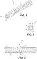
- FIG. 6 shows an exemplary electrical contact 120 that includes fewer wires 126 than the electrical contact 20 shown in Figs. 1-5 .
- the electrical contact 120 includes two wires 126 formed in helical configurations, and the wires 126 are generally ribbon-like and have a relatively flatter cross-section.
- the two helical wires 126 remain parallel to each other as they extend along the length of the tubular body 24.
- the two helical wires 126 are approximately 180 degrees out of phase with respect to each other.
- multiple helical wires may be provided in a criss-cross configuration (e.g., contacting each other at one or more locations) or a braided configuration.
- the electrical contact may include a single wire (e.g., in a helical or mesh configuration, etc.) or other substantially continuous wire configuration.
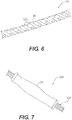
- Fig. 7 shows an exemplary electrical contact 220 that includes more wires 226 than the electrical contact 20 shown in Figs. 1-5 .
- the electrical contact 220 includes a plurality of wires 226 that extend generally longitudinally (axially) and are relatively straight and generally parallel to the longitudinal axis and to each other.
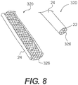
- Figs. 8-10 show an exemplary electrical contact 320 that includes wires 326 provided in a braided or criss-cross configuration.
- the wires 326 may be attached or joined together (e.g., joined with adhesive, formed continuously, etc.), or may be braided together at the locations where the wires 326 cross.
- Fig. 8 shows the electrical contact 320 cut open for illustrative purposes only. With the braided configuration, certain portions or wires 326 of the braided configuration may be embedded in the tubular body 24, and certain portions or wires 326 of the braided configuration may not be embedded in the tubular body 24.
- the portions or wires 326 that are not embedded in the tubular body 24 may be connected to the tubular body 24 by the portions or wires 326 that are embedded in the tubular body 24, which are braided or criss-crossed with the non-embedded portions or wires 326.
- other configurations of wires may be provided, such as a mesh.
- the configuration of the wires 26, 126, 226, 326 may be selected based on various factors, such as a desired amount of exposed surface area that may contact the pin or other conductive structure inserted into the channel 22.
- the wires 26 may be embedded within the tubular body 24.
- the wires 26 may retain their positioning with respect to the tubular body 24 as a pin or other conductive structure (e.g., from the receptacle connector) is inserted into and/or removed from the channel 22.
- the wires 26 are substantially prevented from obstructing the channel 22, so that the pin or other conductive structure (e.g., from the receptacle connector) may enter the channel 22.
- each wire 26 may be embedded within the tubular body 24, as shown in Figs. 3-5 .
- less than a majority (e.g., less than 50%, etc.) of each wire 26 may be embedded within the tubular body 24.
- the remaining portion of each wire 26 (or the surface thereof) is exposed within the channel 22.
- the pin or other conductive structure may contact and form an electrical connection with the exposed portions of the wires 26 when inserted into the channel 22.
- each electrical contact 20 may provide a separate electrical connection between the wires 26 and the pin or other conductive structure inserted into the channel 22 in the respective electrical contact 20.
- the dimension of the channel 22 (e.g., the diameter of the inner surfaces of the wires 26) may be slightly smaller than the dimensions of the pin or other conductive structure (e.g., the diameter of the outer surface configured to contact the wires 26).
- the polymeric and/or elastomeric material of the tubular body 24 may expand when the pin or other conductive structure is inserted into the channel 22.
- the polymeric and/or elastomeric material of the tubular body 24 may also provide sufficient radial pressure or force when the pin or other conductive structure is inserted into the channel 22 such that the wires 26 may be maintained in contact with the pin or other conductive structure (e.g., to prevent the pin or other conductive structure from inadvertently slipping out of the channel 22 as well as to provide sufficient normal force to ensure an uninterrupted connection having low resistance).
- the dimensions of the tubular body 24 may be selected to ensure that sufficient radial pressure is applied to the pin or other conductive structure when inserted into the channel 22.
- the wires 26 may be pre-biased in the inward radial direction, which may result in an improved amount of surface area contact with the pin or other conductive structure when it is inserted. This may also result in an improved electrical connection between the electrical contact 20 and the pin. Moreover, having a plurality of such wires 26 may increase the amount of surface area contact with the pin.
- the tubular body 24 and the wires 26 may be formed using various methods.
- the tubular body 24 and the wires 26 may be formed such that the tubular body 24 and the wires 26 are seamless and continuous.
- the tubular body 24 may be continuously tubular and may have a constant cross-section, and the wires 26 may extend continuously along the length (or axis) of the tubular body 24 without any cuts along the cross-sections of the wires 26.
- the wires 26 may be braided, wound, or otherwise positioned over a wire core (not shown), which may be, for example, a cylindrical member.
- the subassembly formed by the wires 26 positioned on the wire core may be run through an extruder to form the tubular body 24 over the wires 26 such that the wires 26 are embedded into the tubular body 24 as shown in Figs. 1-5 .
- the wire core may be removed to produce a continuous and seamless length of the tubular body 24 with the wires 26 embedded therein, which may be divided or cut into multiple individual electrical contacts 20.
- the individual electrical contacts 20 may then be continuous and seamless.
- multiple subassemblies including the wires 26 positioned on the respective wire cores
- the wires 26 may be braided, wound, or otherwise positioned over the wire core, and a tube formed of the material for forming the tubular body 24 (e.g., a polymer or other material capable of softening when heated, or other similar material) may be slipped over the subassembly formed by the wires 26 positioned on the wire core.
- a shrink tube (not shown) may be slipped over the polymer tube.
- the assembly including the shrink tube, the polymer tube, the wires 26, and the wire core, may be heated, which may cause the shrink tube to shrink and apply radial pressure against the polymer tube while the polymer tube softens.
- the shrink tube and the wire core may be removed to produce a continuous and seamless length of the tubular body 24 with the wires 26 embedded therein, which may be divided or cut into multiple individual electrical contacts 20.
- the individual electrical contacts 20 may then be continuous and seamless.
- the lengths of the individual electrical contacts 20 may be determined based on the intended applications. For example, in certain applications, the lengths of the electrical contacts 20 may range from approximately 12 millimeters (0.5 inches) to approximately 305 millimeters (12 inches). Since the electrical contacts 20 may be divided or cut from a continuous and seamless length of the tubular body 24 with the wires 26 embedded therein, manufacturing and assembling the electrical contacts 20 may be easier and less expensive.
- the dimensions of the electrical contact 20 may be scaled up or down relatively easily.
- the electrical contact 20 may be relatively inexpensive to manufacture and may require minimal assembly. Minimal tooling (e.g., an extrusion die) may be required to form the electrical contact 20.
- the housing 30 shown in Figs. 1 and 2 may be omitted, replaced, or substituted by other carrier devices that may be attached to the ends of one or more of the electrical contacts 20 to form a contact assembly and/or an electrical connector.
- Various exemplary electrical connections provided by the electrical contacts 20, 320 will now be described.
- an electrical connection may be formed by connecting the electrical contact 20 to an insulated conductor 40 (e.g., an insulated wire) or other termination device that is at least partially inserted into the electrical contact 20.
- the conductor 40 may include a conductive inner portion 42 and an insulative outer portion 44 surrounding the inner portion 42 along at least a portion of the length of the inner portion 42, with an end of the inner portion 42 extending outward from the outer portion 44.
- the inner portion 42 may be formed from an electrically conductive material, such as any of the materials described above for forming the wires 26.
- the outer portion 44 may be electrically insulative.
- the entire conductor 40 may be formed of a conductive material.
- the inner portion 42 may be electrically connected to the wires 26 of the electrical contact 20.
- a pin or other conductive structure e.g., of a receptacle connector
- the pin 80 of Fig. 31 may be inserted into the channel 22 of the electrical contact 20 to electrically connect to the inner portion 42, thereby establishing an electrical connection with the conductor 40 and the electrical contact 20.
- Fig. 11 shows a contact assembly 410 formed by soldering the conductor 40 to the electrical contact 20, according to an exemplary embodiment.
- the electrical contact 20 Before soldering the conductor 40 to the electrical contact 20, the electrical contact 20 may be prepared. For example, a portion of the electrical contact 20 may be cut away to form a solder cup 28 at the end of the electrical contact 20, when the electrical contact 20 is positioned horizontally, as shown in Fig. 11 .
- the exposed end of the inner portion 42 of the conductor 40 may be sized to be received in the portion of the channel 22 in the solder cup 28. After inserting the exposed end of the inner portion 42 in the solder cup 28, solder may be applied to the solder cup 28 to solder the wires 26 in the solder cup 28 to the exposed end of the inner portion 42.
- the inner portion 42 may be electrically connected to the wires 26 of the electrical contact 20.
- a shrink tube or ferrule 46 ( Figs. 14 and 15 ) may be provided to cover and support the connection between the conductor 40 and the electrical contact 20 (e.g., the solder cup 28). Accordingly, an electrical connection may be provided between the conductor 40 and the electrical contact 20.
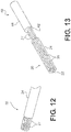
- Figs. 12-15 show a contact assembly 412 formed by soldering or crimping the electrical contact 20 to the conductor 40, according to an exemplary embodiment.
- the electrical contact 20 Before soldering or crimping the conductor 40 to the electrical contact 20, the electrical contact 20 may be prepared. For example, as shown in Fig. 12 , a portion of the tubular body 24 of the electrical contact 20 may be cut away to expose ends 27 of the wires 26, e.g., using a wire strip tool. As shown in Fig. 13 , the exposed end of the inner portion 42 of the conductor 40 may be placed between the exposed ends 27 of the wires 26. The exposed ends 27 of the wires 26 may be soldered to the exposed end of the inner portion 42 of the conductor 40. As shown in Figs.
- a shrink tube or ferrule 46 (e.g., a crimp ferrule) may be provided to cover and support the connection between the conductor 40 and the electrical contact 20.
- the exposed ends 27 of the wires 26 may be crimped to the exposed end of the inner portion 42 of the conductor 40 using the ferrule 46 (e.g., a crimp ferrule).
- the inner portion 42 may be electrically connected to the wires 26 of the electrical contact 20.
- the end of the electrical contact 20 may be crimped onto the exposed end of the inner portion 42 of the conductor 40 using the crimp ferrule 46. Accordingly, an electrical connection may be provided between the conductor 40 and the electrical contact 20.
- a contact assembly may be formed by connecting another type of termination device, such as an end cap 50, to the electrical contact 20.
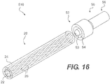
- Figs. 16 and 17 show a contact assembly 510 formed by connecting the end cap 50 to the electrical contact 20, according to an exemplary embodiment.
- the end cap 50 may be formed at least partially from an electrically conductive material, such as any of the materials described above for forming the wires 26.
- the end cap 50 may include a first end 52 for connecting to the electrical contact 20.
- the first end 52 may include a protrusion 53 formed by an annular gap 54. As shown in Fig.
- the annular gap 54 may be sized to receive an end of the electrical contact 20, and the protrusion 53 may be sized to be inserted into the channel 22 of the electrical contact 20.
- the end of the electrical contact 20 may be press fit into the annular gap 54 in the end cap 50, thereby simplifying the connection of the end cap 50 to the electrical contact 20.
- the contact assembly 510 may be configured to provide an electrical connection between the end cap 50 and the electrical contact 20.
- the end cap 50 may also include a second end 56 configured to provide an interface for attaching to other connectors or components. As a result, the end cap 50 may provide an electrical connection between those connectors or components and the electrical contact 20.
- the end cap 50 shown in Figs. 16 and 17 may include a crimp barrel 57 or other opening or cavity sized for inserting, e.g., a stranded wire or other conductive structure, thereby establishing an electrical connection between the stranded wire and the electrical contact 20 via the end cap 50.
- the end cap 50 may include other types of attachment structures, such as a solder cup, a printed circuit board (PCB) tail, or other conventional attachment structures.
- PCB printed circuit board
- the electrical contacts and/or contact assemblies described above may be connected to a housing (e.g., housing 30 described in connection with Figs. 1 and 2 , or other housing) to form an electrical connector.
- a housing e.g., housing 30 described in connection with Figs. 1 and 2 , or other housing
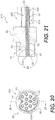
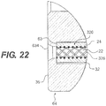
- Figs. 18-22 show an electrical plug (or socket) connector 610 formed by connecting a plurality of the electrical contacts 320 to a housing 60, according to another exemplary embodiment.
- the housing 60 may be generally similar to the housing 30 shown in Figs. 1 and 2 , and may also include a base portion 62 connected to a plug portion 64 for inserting into a receptacle portion 72 ( Figs. 23-30 , 32 , and 33 ) in an electrical receptacle connector 700 ( Figs.
- the housing 60 may include eleven cavities 32 extending through the axial length of the housing 60, e.g., through the base and plug portions 62, 64, as shown in Fig. 21 .
- the housing 60 may include eleven cavities 32, but alternatively, fewer or more than eleven cavities 32 may be provided, e.g., depending on the application.
- the cavities 32 may form openings 634 in the face 36 of the plug portion 64 of the housing 60.
- the openings 634 may be slightly narrower than a remaining portion of the cavities 32 such that a surface 63 may be formed against which the ends of the electrical contacts 320 may abut when inserted into the cavities 32 in the housing 60.
- the openings 634 may include chamfers that widen the openings 634 towards the face 36.
- the housing 60 may be formed of polyetherimide (PEI), other polymers, or other similar materials.
- the diameter of the cavities 32 may be approximately 0.68 to 0.70 millimeters (0.027 to 0.028 inches) and the diameter of the openings 634 may be approximately 0.36 millimeters (0.014 inches).
- the housing 60 may be approximately 4.9 millimeters (0.193 inches) long, the plug portion 64 may have an outer diameter of approximately 3.27 millimeters (0.129 inches), and the base portion 62 may have an outer diameter of approximately 3.89 millimeters (0.153 inches).
- a plurality of the electrical contacts 320 may be inserted through the respective cavities 32 in the housing 60.
- the electrical contacts 320 may be permanently attached to the inner surfaces of the respective cavities 32, e.g., using an adhesive.
- the electrical contacts 320 may be attached to the inner surfaces of the respective cavities 32, e.g., using a cable connector or cable gland, such as a threaded connection, such that the electrical contacts 320 may be removed.
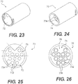
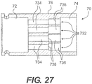
- Figs. 23-27 show a housing 70 of the receptacle connector 700 ( Figs. 28-30 , 32 , and 33 ) for connecting to the plug connector 610 shown in Figs. 18-22 , according to an exemplary embodiment.
- the housing 70 may include a first receptacle portion 72 at a first end and a second receptacle portion 74 at the second, opposite end.
- the first and second receptacle portions 72, 74 are joined by an intermediate portion 76 of the housing 70.
- the intermediate portion 76 includes one or more cavities 732 extending through the axial length of the intermediate portion 76.
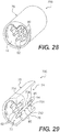
- Figs. 28-30 show the receptacle connector 700 for connecting to the plug connector 610 shown in Figs. 18-22 , according to an exemplary embodiment.
- the receptacle connector 700 may include the housing 70 shown in Figs. 23-27 .
- the housing 70 may include eleven cavities 732 (corresponding to the eleven cavities 32 in the housing 60 of the plug connector 610), but alternatively, fewer or more than eleven cavities 732 may be provided, e.g., depending on the application.
- the cavities 732 in the housing 70 may be sized to each receive a pin 80.
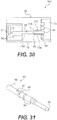
- Fig. 31 shows the pin 80, according to an exemplary embodiment.
- the pin 80 may include a tip portion 82 and a tail portion 84, which may include a flange or shoulder 86.
- the tip portion 82 may include a bullet nose serving as a mating lead-in.
- the pin 80 may also include one or more press-fit barbs 83 to assist in retention of the pin 80 when the pin 80 is press fit into the housing 70.
- the tail portion 84 may include a crimp barrel 85, as shown in Figs. 29 and 30 , which may receive a stranded wire (not shown) and may be crimped to connect to the wire.
- the tail portion 84 may also include a hole 87, as shown in Fig. 31 , to facilitate plating.
- Each cavity 732 in the housing 70 may include a first portion 734 configured to receive the tip portion 82 of the corresponding pin 80 and a second portion 736 configured to receive the tail portion 84 of the corresponding pin 80.
- the second portions 736 may be slightly wider than the first portions 734 such that a surface 738 may be formed against which the flanges 86 of the pins 80 may abut when inserted into the cavities 732 in the housing 70, as shown in Figs. 29 and 30 .
- the flanges 86 may serve as positive stops for the pins 80 during installation of the pins 80 in the housing 70.
- the tip portions 82 of the pins 80 may extend into the first receptacle portion 72 of the housing 70 and the tail portions 84 of the pins 80 may extend into the second receptacle portion 74 of the housing 70, as shown in Figs. 29 and 30 .
- the pins 80 may be attached to the housing 70 by potting (filling) or over-molding the end of the housing 70 that includes the second receptacle portion 74 after the wires (not shown) are connected to the tail portions 84 of the pins 80, e.g., via the crimp barrels 85.
- the pins 80 may be permanently attached to the inner surfaces of the respective first portions 734 and/or second portions 736 of the cavities 732, e.g., using an adhesive.
- the pins 80 may be attached to the inner surfaces of the cavities 732, e.g., using a cable connector or cable gland, such as a threaded connection, such that the pins 80 may be removed.
- Figs. 32 and 33 show the plug connector 610 connected to the receptacle connector 700, according to an exemplary embodiment.
- the plug portion 64 may be inserted into the receptacle portion 72 of the receptacle connector 700 and the pins 80 in the receptacle connector 700 may be inserted through the openings 634 in the face 36 of the housing 60 of the plug connector 610.
- the pins 80 may be received within the channels 22 in the electrical contacts 320 disposed within the cavities 32 in the housing 60 of the plug connector 610.
- an electrical connection is formed between the wires 326 in the electrical contacts 320 and the pins 80.
- the fit between the electrical contacts 320 and the housing 60 within the cavities 32 may leave little room for radial expansion of the electrical contacts 320 when the pins 80 are inserted into the electrical contacts 320.
- the electrical contacts 320 may be compressed against the surface of the cavities 32 in the housing 60, thereby providing radial pressure or force on the pins 80 such that the wires 326 in the electrical contacts 320 may be maintained in contact with the pins 80 (e.g., to prevent the pins 80 from inadvertently slipping out of the channels 22 as well as to provide sufficient normal force to ensure an uninterrupted connection having low resistance).
- the first portions 734 of the cavities 732 may have a diameter of approximately 0.48 millimeters (0.0189 inches) and a length of approximately 1.87 millimeters (0.074 inches)
- the second portions 736 of the cavities 732 may have a diameter of approximately 0.66 millimeters (0.026 inches)
- the total length of the cavities 732 may be approximately 3.00 millimeters (0.118 inches)
- the housing 70 may have an outer diameter of approximately 3.89 millimeters (0.153 inches) and a length of approximately 7.00 millimeters (0.276 inches)
- the first receptacle portion 72 may have an inner diameter of approximately 3.33 millimeters (0.131 inches) and length of approximately 2.50 millimeters (0.098 inches)
- the second receptacle portion 74 may have an inner diameter of approximately 3.33 millimeters (0.131 inches).
- the housing 70 may be formed of polyetherimide (PEI), other polymers, or other similar materials.
- termination devices, housings, carrier devices, and other components for connecting to the electrical contacts 20 are described above, e.g., the housings 30, 60, the conductors 40, the end caps 50, the pins 80, etc., to form a contact assembly and/or an electrical connector.
- the termination devices, housings, carrier devices, and other components may be provided interchangeably.
- One type of termination device, housing, carrier device, or other component may be attached to one end of the electrical contact(s) 20 and another type of termination device, housing, carrier device, or other component may be attached to the opposite end of the electrical contact(s) 20.
- Fig. 34 shows the electrical contact 20 for directly connecting to two of the pins 80 of Fig. 31 , e.g., without including a separate termination device, housing, carrier device, or other component.
- the respective pins 80 may be received within the channel 22 of the electrical contact 20 at opposite ends of the electrical contact 20 to form a contact assembly.
- the electrical contact 20 may serve as a flexible socket for the pins 80.
- the pins 80 may have a greater outer diameter (or other dimension) than the inner diameter (or other dimension) of the wire(s) 26 and/or the tubular body 24 forming the channel 22.
- the elasticity of the electrical contact 20 may limit the radial expansion of the electrical contact 20 when the pins 80 are inserted into the electrical contact 20.
- the electrical contact 20 may provide a compressive radial pressure or force on the pins 80 such that the wire(s) 26 in the electrical contact 20 may be maintained in contact with the pins 80 (e.g., to prevent the pins 80 from inadvertently slipping out of the channel 22 as well as to provide sufficient normal force to ensure an uninterrupted connection having low resistance).
- the ends of the electrical contact 20 may receive other types of conductive structures other than the pins 80 for electrical connections between the electrical contact 20 and the conductive structures.
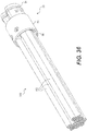
- the electrical contact 20 may be formed in various configurations.
- the electrical contact 20 may include more than one channel 22 such that the electrical contact 20 is formed with a multi-lumen configuration.
- Fig. 35 shows an electrical contact 420 including a seamless and continuous tubular body 424 with wires 26 embedded into the tubular body 424 to form multiple channels 22 extending substantially longitudinally through the tubular body 424.
- the electrical contact 420 includes three channels 22, but alternatively, fewer or more than three channels 22 may be provided, e.g., depending on the application.
- the tubular body 424 may be extruded or otherwise formed over the wires 26 of the multiple channels 22 simultaneously.
- Figs. 36-40 show another embodiment of an electrical plug (or socket) connector 900 formed by inserting a plurality of the electrical contacts 320 into a housing 90.
- the housing 90 may include a base portion 92 connected to a plug portion 94 for insertion into the receptacle portion 72 in the electrical receptacle connector 700 ( Figs. 23-30 , 32 , and 33 ), as shown in Fig. 40 and as will be described below.
- the housing 90 may include eleven cavities 95 extending through at least a portion of the axial length of the housing 90, e.g., through at least a portion of the base portion 92 and at least a portion of the plug portion 94 as shown in Fig. 37 , or alternatively through at least a portion of the plug portion 94 only.
- eleven cavities 95 may be provided, but alternatively, fewer or more than eleven cavities 95 may be provided, e.g., depending on the application.
- the plurality of cavities 95 connect to an opening 96 that extends from the face of the base portion 92 of the housing 90 and at least partially through the base portion 92 as shown in Fig. 37 .
- the opening 96 may extend through at least a portion of the base portion 92 and at least a portion of the plug portion 94.
- the cavities 95 may form plug-side openings 934 in the face of the plug portion 94 of the housing 90.
- the plug-side openings 934 may be slightly narrower than a remaining portion of the cavities 95 such that a surface 93 may be formed against which the ends of the electrical contacts 320 may abut when inserted into the cavities 95 in the housing 90.
- the plug-side openings 934 may include chamfers that widen the plug-side openings 934 towards the face of the plug portion 94 of the housing 90.
- the housing 90 may be formed of similar materials as described above in connection with the other housings and carrier devices. Also, the dimensions of the housing 90, the plug portion 94, the base portion 92, the cavities 95, and/or the openings 934 may be similar to the dimensions described above in connection with the similar features of other housings and carrier devices.
- a plurality of the electrical contacts 320 may be inserted through the opening 96 and into the respective cavities 95 in the housing 90.
- the electrical contacts 320 may be permanently or removably attached to the inner surfaces of the respective cavities 95, e.g., using an adhesive, a threaded connection, etc.
- a gasket 100 may also be inserted into the opening 96 of the housing 90.
- the gasket 100 may be formed of, for example, a rubber or elastomeric material or other material used for forming seals, and may be attached to the housing 90, e.g., using an adhesive.
- the gasket 100 may include a base portion 102 and a plurality of protrusions 104 (e.g., eleven protrusions 104 or other number corresponding to the number of cavities 95 in the housing 90) extending from the base portion 102.
- the protrusions 104 are positioned on the base portion 102 so that, when the gasket 100 is inserted into the opening 96 of the housing 90, the protrusions 104 may be inserted at least partially into the respective cavities 95.
- a face of the base portion 102 of the gasket 100 from which the protrusions 104 extend may be positioned flush against a corresponding inner surface of the housing 90 defining the opening 96, as shown in Figs. 37 and 40
- the gasket 100 may include a plurality of cavities 105 (e.g., eleven cavities 105 or other number corresponding to the number of cavities 95 in the housing 90). Each cavity 105 in the gasket 100 may be sized to receive one of the pins 80 ( Fig. 31 ) or other type of pin, as shown in Figs. 37-40 . Each cavity 105 may include a first portion 106 configured to receive a portion of the tip portion 82 of the corresponding pin 80 and a second portion 107 configured to receive at least a portion of the tail portion 84 of the corresponding pin 80.
- the second portions 107 may be slightly wider than the first portions 106 such that a surface may be formed against which the flanges 86 of the pins 80 may abut when inserted into the cavities 105 in the gasket 100, as shown in Figs. 37 , 39 , and 40 .
- the flanges 86 may serve as positive stops for the pins 80 during installation of the pins 80 in the gasket 100.
- the tip portions 82 of the pins 80 may extend into the channels 22 of the respective electrical contacts 320 positioned in the cavities 95 in the housing 90.
- the tip portions 82 may be press fit into the channels 22 of the respective electrical contacts 320.
- the tail portions 84 of the pins 80 may extend into the opening 96 of the housing 90, as shown in Figs. 37 and 40 .
- Insulated wires 110 or other conductive structures may be connected to the tail portions 84 of the respective pins 80.
- a wire portion of the insulated wires 110 may be connected to the respective tail portions 84 of the pins 80 (e.g., the crimp barrels 85).
- the tail portions 84 of the pins 80 may be connected to other types of connection structures, such as PCB terminations or tails, etc.
- Assembly of the electrical plug connector 900 may include the steps of inserting the electrical contacts 320 into the respective cavities 95 of the housing 90 and then pressing the gasket 100 into the opening 96 of the housing 90.
- the gasket 100 may be pressed into the opening 96 until the protrusions 104 are inserted at least partially into the respective cavities 95 to push the electrical contacts 320 until the electrical contacts 320 contact the surface 93.
- the pins 80 e.g., separate or connected to the insulated wires 110, PCB tails, etc.
- the pins 80 may be pressed into the respective cavities 105 in the gasket 100.
- the flanges 86 of the pins 80 may serve as retention barbs to lock the pins 80 in place with respect to the gasket 100 and to lock the gasket 100 in place with respect to the housing 90 by expanding out the gasket 100 when the flanges 86 are inserted into the gasket 100.
- the expansion of the gasket 100 assists in providing the press fit connection of the gasket 100 to the housing 90.
- the press fit connection of the pins 80 to the gasket 100 and the press fit connection of the gasket 100 to the housing 90 may serve to lock the pins 80 and the gasket 100 in place with respect to the housing 90.
- epoxy or other thermosetting polymer or other material
- potting compound or over-molding may be applied to the assembled components to hold one or more of the components of the assembled electrical plug connector 900 together, to provide strain relief for the wires 110, to improve ergonomics, to improve appearance, etc.
- the gasket 100 may serve as a seal to prevent water and other undesirable elements outside the housing 90 from reaching the electrical contacts 320.
- the gasket 100 may be dimensioned such that the outer peripheral surface of the gasket 100 tightly seals against the inner surface of the opening 96 of the housing 90 and against an outer surface of the pins 80.
- the gasket 100 may be compressed when inserted into the opening 96 of the housing 90 in order to form the seal (e.g., like a stopper or plug). As a result, the gasket 100 may press against the pins 80 and the housing 90 to form the seal between the pins 80 and the housing 90.
- the electrical contacts 320 are relatively shorter, and may be contained substantially or entirely within the housing 90.
- the electrical contacts 320 may be contained substantially or entirely within the cavities 95 in the housing 90, and the gasket 100 may position and retain the electrical contacts 320 inside the cavities 95 of the housing 90.
- the gasket 100 may ensure that the electrical contacts 320 are pushed forward in the housing 90, e.g., to contact the surface 93 ( Fig. 39 ) of the housing 90. As a result, a more stable and secure electrical connection may be obtained, depending on the application.
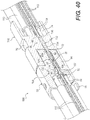
- Fig. 40 shows the plug connector 900 connected to the receptacle connector 700 of Figs. 23-30 , 32 , and 33 , according to an exemplary embodiment.
- the plug portion 94 may be inserted into the receptacle portion 72 of the receptacle connector 700 and the pins 80 in the receptacle connector 700 may be inserted through the openings 934 in the face of the housing 90 of the plug connector 900.
- the pins 80 in the receptacle connector 700 may be received within the channels 22 in the electrical contacts 320 disposed within the cavities 95 in the housing 90 of the plug connector 900.
- the fit between the electrical contacts 320 and the housing 90 within the cavities 95 may leave little room for radial expansion of the electrical contacts 320 when the pins 80 (from the plug connector 900 and/or the receptacle connector 700) are inserted into the electrical contacts 320.
- the electrical contacts 320 may be compressed against the surface of the cavities 95 in the housing 90, thereby providing radial pressure or force on the pins 80 such that the wires 326 in the electrical contacts 320 may be maintained in contact with the pins 80 (e.g., to prevent the pins 80 from inadvertently slipping out of the channels 22 as well as to provide sufficient normal force to ensure an uninterrupted connection having low resistance).
- the pins 80 provided in the plug connector 900 may differ in structure and/or dimensions from the pins 80 provided in the receptacle connector 700. In certain embodiments, the pins 80 provided in the plug connector 900 may be intended for fewer engagement cycles. For example, the plug connector 900 may be formed by inserting the pins 80 into the gasket 100 and the electrical contacts 320 once (a single engagement cycle). Therefore, the pins in the plug connector 900 may have a relatively larger outer dimension (e.g., outer diameter) than the pins 80 provided in the receptacle connector 700 to assist in ensuring a stable connection.
- outer dimension e.g., outer diameter
- the pins 80 provided in the receptacle connector 700 may be intended for more frequent insertion and removal from the electrical contacts 320 (a higher number of engagement cycles) as the plug connector 900 is connected to and disconnected from the receptacle connector 700. Therefore, the pins in the receptacle connector 700 may have a relatively smaller outer dimension (e.g., outer diameter) to reduce wear on the pins of the receptacle connector 700 and/or the electrical contacts 320.
- the disclosed electrical connectors may replace conventional electrical connectors, and may be used for a variety of applications, such as aerospace, defense, and commercial applications.
- the disclosed electrical connectors may replace electrical connectors having wires that form a hyperboloid.
- the disclosed electrical connectors may retain some of the benefits of such connectors, such as providing a reliable electrical connection, but may also have a smaller size (e.g., diameter), be less expensive, and/or be less difficult to manufacture.
Description
- The present disclosure relates generally to an electrical contact, and more particularly, to materials, components, and methods directed to the fabrication and use of an electrical contact with embedded wiring.
- A conventional electrical connector may include a flexible pin member that is received within a tubular receiving connector member to form an electrical connection. For example,
U.S. Patent No. 4,437,726 to Lambert ("the '726 patent") discloses a flexible pin member for inserting into a tubular receiving connector. The flexible pin member includes a pair of fingers that curve away from each other and then toward each other along the lengths of the fingers. As the fingers are inserted into a tubular receiving connector, the relatively wider portion of the pin member (formed where the fingers curve away from each other) is compressed and slides against an inner surface of the tubular receiving connector, thereby resulting in an electrical connection between the flexible pin member and the tubular receiving connector. - The electrical connector of the '726 patent, however, includes components, such as the fingers, that may be complex to manufacture. For example, due to the size and/or shape of the fingers, the fingers may generally be expensive and difficult to manufacture. Also, for applications that may need smaller electrical connectors, it may be difficult to decrease the size of the fingers without significantly increasing the cost and difficulty in manufacturing.
- Other electrical connectors may include wires that form a hyperboloid. There may generally be a limit to how small such connectors may be made. Also, due to their manufacturing complexity and number of components, such connectors may generally be expensive.
- The disclosed embodiments are directed to overcoming one or more of the problems set forth above.
-
US 5 350 318 discloses a two component leadwire system for electrical connection between biomedical electrodes and electrical equipment for diagnostic or therapeutic use. One leadwire component has a bayonet terminus and a second leadwire is an inexpensively-made receptacle for making electrical contact with the bayonet. The receptable has a socket for receiving the bayonet and an electrical conductor surrounded by a resilient, insulative sheath. When the bayonet is inserted into the socket, the sheath resiliently grips the bayonet and holds the bayonet in electrical contact with the conductor. -
US 4 416 498 discloses a socket-type connector used for making electric connection between two circuit units in which at least a part of the socket is made of an electrically insulating and elastically resilient material so that a pin plug inserted into the socket is held firmly and in good reliable contact with the contacting element. - The present invention is defined by the claims.
- In accordance with a further embodiment, a method of forming an electrical connector includes forming at least one wire partially embedded into a tubular body. The tubular body is formed of a flexible and insulative material. The at least one wire is formed of a conductive material. The tubular body includes an inner surface. At least a portion of the at least one wire is exposed within the inner surface of the tubular body so that at least a portion of the inner surface of the tubular body and at least the exposed portion of the at least one wire forms a channel.
- Additional embodiments and advantages will be set forth in part in the description which follows, and in part will be obvious from the description, or may be learned by practice of the disclosure. The embodiments and advantages will be realized and attained by means of the elements and combinations particularly pointed out below.
- It is to be understood that both the foregoing general description and the following detailed description are exemplary and explanatory only and are not restrictive of the disclosure.
- The accompanying drawings, which are incorporated in and constitute a part of this specification, illustrate several embodiments and together with the description, serve to explain the principles of the disclosure.
-
Fig. 1 is a perspective view of an electrical connector, according to an exemplary embodiment; -
Fig. 2 is a cross-sectional view of the electrical connector ofFig. 1 ; -
Fig. 3 is a perspective view of an electrical contact of the electrical connector ofFigs. 1 and2 having wires in a helical configuration; -
Fig. 4 is a front view of the electrical contact ofFig. 3 ; -
Fig. 5 is a cross-sectional side view of the electrical contact ofFig. 3 ; -
Fig. 6 is a perspective view of an electrical contact having wires in a helical configuration, according to an alternative embodiment; -
Fig. 7 is a perspective view of an electrical contact having wires in a generally straight configuration, according to another alternative embodiment; -
Fig. 8 is a perspective view of electrical contacts having wires in a braided configuration, according to a further alternative embodiment; -
Fig. 9 is a front view of one of the electrical contacts ofFig. 8 ; -
Fig. 10 is a cross-sectional side view of one of the electrical contacts ofFig. 8 ; -
Fig. 11 is a perspective view of a contact assembly including a conductor and an electrical contact, according to an exemplary embodiment; -
Fig. 12 is a perspective view of an electrical contact having embedded wires with exposed ends, according to an exemplary embodiment; -
Fig. 13 is a perspective view of a contact assembly including a conductor and the electrical contact ofFig. 12 ; -
Fig. 14 is a perspective view of the contact assembly ofFig. 13 including a crimp ferrule; -
Fig. 15 is a cross-sectional perspective view of the contact assembly ofFig. 14 ; -
Fig. 16 is a perspective view of an end cap and an electrical contact, according to an exemplary embodiment; -
Fig. 17 is a cross-sectional perspective view of a contact assembly formed by attaching the end cap and the electrical contact ofFig. 16 ; -
Fig. 18 is a perspective view of a first end of a plug connector, according to an exemplary embodiment; -
Fig. 19 is a perspective view of a second end of the plug connector ofFig. 18 ; -
Fig. 20 is a front view of the plug connector ofFig. 18 ; -
Fig. 21 is a cross-sectional side view of the plug connector ofFig. 18 ; -
Fig. 22 is a partial cross-sectional side view of the plug connector ofFig. 18 ; -
Fig. 23 is a perspective view of a first end of a housing for a receptacle connector, according to another exemplary embodiment; -
Fig. 24 is a perspective view of a second end of the housing ofFig. 23 ; -
Fig. 25 is a front view of the housing ofFig. 23 ; -
Fig. 26 is a rear view of the housing ofFig. 23 ; -
Fig. 27 is a cross-sectional side view of the housing ofFig. 23 ; -
Fig. 28 is a perspective view of a receptacle connector including the housing ofFig. 23 and a plurality of pins, according to an exemplary embodiment; -
Fig. 29 is a cross-sectional perspective view of the receptacle connector ofFig. 28 ; -
Fig. 30 is a cross-sectional side view of the receptacle connector ofFig. 28 ; -
Fig. 31 is a perspective view of the pin ofFig. 28 ; -
Fig. 32 is a cross-sectional side view of the plug connector ofFig. 18 and the receptacle connector ofFig. 28 ; -
Fig. 33 is a cross-sectional side view of the plug connector ofFig. 18 mated to the receptacle connector ofFig. 28 ; -
Fig. 34 is a perspective view of a contact assembly including the electrical contact ofFigs. 1-5 connected to two of the pins ofFig. 31 ; -
Fig. 35 is a perspective view of a multi-lumen electrical contact, according to an exemplary embodiment; -
Fig. 36 is a perspective view of a plug connector, according to an exemplary embodiment; -
Fig. 37 is a cross-sectional perspective view of the plug connector ofFig. 36 ; -
Fig. 38 is an exploded view of the plug connector ofFig. 36 ; -
Fig. 39 is a cross-sectional exploded view of the plug connector ofFig. 36 ; and -
Fig. 40 is a cross-sectional perspective view of the plug connector ofFig. 36 mated to a receptacle connector. - Reference will now be made in detail to exemplary embodiments, examples of which are illustrated in the accompanying drawings. Wherever possible, the same reference numbers will be used throughout the drawings to refer to the same or like parts.
-
Figs. 1 and2 show anelectrical connector 10, according to an exemplary embodiment. In the exemplary embodiment, theelectrical connector 10 is a plug (or socket) connector that is configured to contact and connect with a receptacle connector (not shown). Theelectrical connector 10 includes one or more electrical contacts (or sockets) 20. As shown inFigs. 3-5 , eachelectrical contact 20 may include achannel 22 for receiving a pin or other conductive structure (e.g., thepin 80 ofFig. 31 ), as will be described bellow in further detail. The term "channel" is used to describe any type of opening or passage extending through theelectrical contact 20, such as the opening or passage shown in the figures, or any other opening or passage that permits entrance of the pin or other conductive structure. The length of theelectrical contact 20 may vary depending on the application. - As shown in
Figs. 1 and2 , theelectrical connector 10 may also include ahousing 30 or other carrier device for receiving theelectrical contact 20. Thehousing 30 or other carrier device may be connected to ends of theelectrical contacts 20. For example, thehousing 30 or other carrier device may permit theelectrical contact 20 to be removably or permanently attached to another component (e.g., a component including a pin or other conductive structure (e.g., thepin 80 ofFig. 31 )) to form an electrical connection with that component, as will be described bellow. Thehousing 30 may be formed of polyetherimide (PEI), liquid crystal polymer (LCP), other polymers, or other similar materials. In certain embodiments, thehousing 30 may also be formed, partially or entirely, from a metal or other conductive materials. - The
housing 30 may include one ormore cavities 32 extending through the axial length of thehousing 30, which formopenings 34 in aface 36 of thehousing 30. The term "cavity" is used to describe any type of opening or passage extending through thehousing 30, such as the opening or passage shown in the figures, or any other opening or passage that permits entrance of theelectrical contact 20. In the embodiment shown inFigs. 1 and2 , thehousing 30 includes sixcavities 32, but alternatively, fewer or more than sixcavities 32 may be provided, e.g., depending on the application. - The
electrical contacts 20 may be inserted at least partially through thecavities 32. As shown inFig. 2 , theelectrical contacts 20 extend through substantially the entire length of thecavities 32. Theelectrical contacts 20 may be permanently attached to the inner surfaces of therespective cavities 32 by a variety of methods, for example, by use of an adhesive. Alternatively, theelectrical contacts 20 may be attached to the inner surfaces of therespective cavities 32 by, e.g., using a cable connector or cable gland, such as a threaded connection, such that theelectrical contacts 20 may be removable. - When a receptacle connector (not shown) is connected to the
electrical plug connector 10, pins (e.g., thepin 80 ofFig. 31 ) in the receptacle connector may be inserted through theopenings 34 in theface 36 of thehousing 30 such that the pins are received by thechannels 22 in theelectrical contacts 20 disposed within thecavities 32 of thehousing 30. When the pins are inserted into thechannels 22 in theelectrical contacts 20, an electrical connection may be formed between the pins of the receptacle connector and theelectrical contacts 20, as will be described below in detail. -
Figs. 3-5 show theelectrical contact 20, according to an exemplary embodiment. Theelectrical contact 20 includes a generallytubular body 24. Thetubular body 24 may be formed from a flexible, insulative material, such as rubber, plastic, thermoplastic, polyurethane, other elastomeric polymers, or other similar polymeric and/or elastomeric materials. Thus, since thetubular body 24 may be formed from an insulative material, thehousing 30 may be formed, partially or entirely, from a conductive material, as described above. Thetubular body 24 may be generally cylindrical, or may have a tubular cross-section of other shapes, such as rectangular, square, oval, etc. In an embodiment, the outer surface of thetubular body 24 may be approximately 0.61 millimeters (0.024 inches) in diameter and the inner surface of thetubular body 24 may be approximately 0.25 millimeters (0.010 inches) in diameter. - One or
more conducting wires 26 may be embedded into the surface of thetubular body 24 so that the exposed portions of thewires 26 and the inner surface of thetubular body 24 between the exposed portions of thewires 26 may form thechannel 22. For example, as shown inFigs. 4 and9 , the exposed portions of the wires 26 (or 326) may form an inner diameter (or other dimension) that is smaller than an inner diameter (or other dimension) of thetubular body 24 so that the exposed portions of the wires 26 (or 326) protrude radially inward from an inner surface of thetubular body 24. Alternatively, the wires 26 (or 326) may form an inner diameter (or other dimension) that is generally similar to the inner diameter (or other dimension) of thetubular body 24. - The
channel 22 may extend at least partially through the structure formed by thetubular body 24 and the exposed portions of thewires 26. For example, as shown inFigs. 3 and 5 , thechannel 22 may extend generally between and through the ends of thetubular body 24, and substantially longitudinally (axially) within thetubular body 24. Thewires 26 may extend substantially longitudinally (axially) along the surface of thetubular body 24, and generally between the ends of thetubular body 24. Thewires 26 may be gold-plated (such as gold-plated beryllium copper) and/or may be made of a variety of materials including, but not limited to, brass, beryllium, copper, and/or any conventional conductive material used for electrical connectors. The possible types of conductive materials may range from materials having relatively lower electrical conductivity (e.g., titanium, stainless steel, etc.), for example, for implantable applications, to materials having relatively higher electrical conductivity. Thewires 26 may have a cross-section that is generally circular, oval, or square, or may have another shape. In an embodiment, thewires 26 may be approximately 0.069 millimeters (0.0027 inches) in diameter. Thewires 26 may be positioned in various configurations. In the exemplary embodiment shown inFigs 1-5 , eightwires 26 with generally circular cross-section are provided, and eachwire 26 is formed in spiral or helical configuration. Alternatively, fewer or more than eightwires 26 may be provided. For example, theelectrical contact 20 may include three, five, ormore wires 26. - Alternative exemplary electrical contacts having different numbers and configurations of wires are shown in
Figs. 6-10 .Fig. 6 shows an exemplaryelectrical contact 120 that includesfewer wires 126 than theelectrical contact 20 shown inFigs. 1-5 . As shown inFig. 6 , theelectrical contact 120 includes twowires 126 formed in helical configurations, and thewires 126 are generally ribbon-like and have a relatively flatter cross-section. In the exemplary embodiment shown inFig. 6 , the twohelical wires 126 remain parallel to each other as they extend along the length of thetubular body 24. Also, in the exemplary embodiment shown inFig. 6 , the twohelical wires 126 are approximately 180 degrees out of phase with respect to each other. Alternatively, multiple helical wires may be provided in a criss-cross configuration (e.g., contacting each other at one or more locations) or a braided configuration. As another alternative, the electrical contact may include a single wire (e.g., in a helical or mesh configuration, etc.) or other substantially continuous wire configuration. -
Fig. 7 shows an exemplaryelectrical contact 220 that includesmore wires 226 than theelectrical contact 20 shown inFigs. 1-5 . As shown inFig. 7 , theelectrical contact 220 includes a plurality ofwires 226 that extend generally longitudinally (axially) and are relatively straight and generally parallel to the longitudinal axis and to each other. -
Figs. 8-10 show an exemplaryelectrical contact 320 that includeswires 326 provided in a braided or criss-cross configuration. Thewires 326 may be attached or joined together (e.g., joined with adhesive, formed continuously, etc.), or may be braided together at the locations where thewires 326 cross.Fig. 8 shows theelectrical contact 320 cut open for illustrative purposes only. With the braided configuration, certain portions orwires 326 of the braided configuration may be embedded in thetubular body 24, and certain portions orwires 326 of the braided configuration may not be embedded in thetubular body 24. The portions orwires 326 that are not embedded in thetubular body 24 may be connected to thetubular body 24 by the portions orwires 326 that are embedded in thetubular body 24, which are braided or criss-crossed with the non-embedded portions orwires 326. Alternatively, other configurations of wires may be provided, such as a mesh. The configuration of thewires channel 22. - The following disclosure refers to the exemplary
electrical contact 20 shown inFigs. 1-5 or theelectrical contact 320 shown inFigs. 8-10 , but it is understood that any of the electrical contacts set forth herein may be substituted for theelectrical contacts - Referring back to the
electrical contact 20 shown inFigs. 1-5 , at least a portion of thewires 26 may be embedded within thetubular body 24. As a result, thewires 26 may retain their positioning with respect to thetubular body 24 as a pin or other conductive structure (e.g., from the receptacle connector) is inserted into and/or removed from thechannel 22. Also, thewires 26 are substantially prevented from obstructing thechannel 22, so that the pin or other conductive structure (e.g., from the receptacle connector) may enter thechannel 22. In an exemplary embodiment, at least a majority (e.g., greater than 50%, 75%, 95%, etc.) of each wire 26 (e.g., a volume or a surface thereof) may be embedded within thetubular body 24, as shown inFigs. 3-5 . Alternatively, less than a majority (e.g., less than 50%, etc.) of each wire 26 (e.g., a volume or a surface thereof) may be embedded within thetubular body 24. The remaining portion of each wire 26 (or the surface thereof) is exposed within thechannel 22. As a result, the pin or other conductive structure may contact and form an electrical connection with the exposed portions of thewires 26 when inserted into thechannel 22. - The
tubular body 24 has sufficient thickness to electrically insulate thewires 26 from an outer surface of thetubular body 24. As a result, eachelectrical contact 20 may provide a separate electrical connection between thewires 26 and the pin or other conductive structure inserted into thechannel 22 in the respectiveelectrical contact 20. - The dimension of the channel 22 (e.g., the diameter of the inner surfaces of the wires 26) may be slightly smaller than the dimensions of the pin or other conductive structure (e.g., the diameter of the outer surface configured to contact the wires 26). Thus, the polymeric and/or elastomeric material of the
tubular body 24 may expand when the pin or other conductive structure is inserted into thechannel 22. The polymeric and/or elastomeric material of thetubular body 24 may also provide sufficient radial pressure or force when the pin or other conductive structure is inserted into thechannel 22 such that thewires 26 may be maintained in contact with the pin or other conductive structure (e.g., to prevent the pin or other conductive structure from inadvertently slipping out of thechannel 22 as well as to provide sufficient normal force to ensure an uninterrupted connection having low resistance). The dimensions of the tubular body 24 (e.g., the diameter of the inner surface of thetubular body 24, the thickness of thetubular body 24, etc.) and/or the pin or other conductive structure (e.g., the diameter of its outer surface configured to contact the wires 26), the configuration (e.g., helical, braided, straight, etc.) and/or dimensions (e.g., the cross-sectional thickness, the size of the exposed portions forming thechannel 22, etc.) of thewires 26, and/or the polymeric and/or elastomeric material used to form the tubular body 24 (e.g., the flexibility of the material) may be selected to ensure that sufficient radial pressure is applied to the pin or other conductive structure when inserted into thechannel 22. As a result, due to the flexibility of thetubular body 24, it may not be necessary to size the components of theelectrical contact 20 and/or the pin or other conductive structure to within as narrow a tolerance when manufacturing the respective components. With the above configuration, thewires 26 may be pre-biased in the inward radial direction, which may result in an improved amount of surface area contact with the pin or other conductive structure when it is inserted. This may also result in an improved electrical connection between theelectrical contact 20 and the pin. Moreover, having a plurality ofsuch wires 26 may increase the amount of surface area contact with the pin. - The
tubular body 24 and thewires 26 may be formed using various methods. In an exemplary embodiment, thetubular body 24 and thewires 26 may be formed such that thetubular body 24 and thewires 26 are seamless and continuous. Thetubular body 24 may be continuously tubular and may have a constant cross-section, and thewires 26 may extend continuously along the length (or axis) of thetubular body 24 without any cuts along the cross-sections of thewires 26. - In an exemplary embodiment, the
wires 26 may be braided, wound, or otherwise positioned over a wire core (not shown), which may be, for example, a cylindrical member. The subassembly formed by thewires 26 positioned on the wire core may be run through an extruder to form thetubular body 24 over thewires 26 such that thewires 26 are embedded into thetubular body 24 as shown inFigs. 1-5 . Then, the wire core may be removed to produce a continuous and seamless length of thetubular body 24 with thewires 26 embedded therein, which may be divided or cut into multiple individualelectrical contacts 20. The individualelectrical contacts 20 may then be continuous and seamless. Alternatively, when forming multipleelectrical contacts 20, multiple subassemblies (including thewires 26 positioned on the respective wire cores) may be formed and may be run together through a single extruder to form the respectivetubular bodies 24 simultaneously. Accordingly, multiple individualelectrical contacts 20 may be extruded together in a single bundle. - In another exemplary embodiment, the
wires 26 may be braided, wound, or otherwise positioned over the wire core, and a tube formed of the material for forming the tubular body 24 (e.g., a polymer or other material capable of softening when heated, or other similar material) may be slipped over the subassembly formed by thewires 26 positioned on the wire core. A shrink tube (not shown) may be slipped over the polymer tube. The assembly including the shrink tube, the polymer tube, thewires 26, and the wire core, may be heated, which may cause the shrink tube to shrink and apply radial pressure against the polymer tube while the polymer tube softens. Then, the shrink tube and the wire core may be removed to produce a continuous and seamless length of thetubular body 24 with thewires 26 embedded therein, which may be divided or cut into multiple individualelectrical contacts 20. The individualelectrical contacts 20 may then be continuous and seamless. - The lengths of the individual
electrical contacts 20 may be determined based on the intended applications. For example, in certain applications, the lengths of theelectrical contacts 20 may range from approximately 12 millimeters (0.5 inches) to approximately 305 millimeters (12 inches). Since theelectrical contacts 20 may be divided or cut from a continuous and seamless length of thetubular body 24 with thewires 26 embedded therein, manufacturing and assembling theelectrical contacts 20 may be easier and less expensive. - Accordingly, the dimensions of the
electrical contact 20 may be scaled up or down relatively easily. Theelectrical contact 20 may be relatively inexpensive to manufacture and may require minimal assembly. Minimal tooling (e.g., an extrusion die) may be required to form theelectrical contact 20. - The
housing 30 shown inFigs. 1 and2 may be omitted, replaced, or substituted by other carrier devices that may be attached to the ends of one or more of theelectrical contacts 20 to form a contact assembly and/or an electrical connector. Various exemplary electrical connections provided by theelectrical contacts - In certain embodiments, an electrical connection may be formed by connecting the
electrical contact 20 to an insulated conductor 40 (e.g., an insulated wire) or other termination device that is at least partially inserted into theelectrical contact 20. As shown inFigs. 11-15 , theconductor 40 may include a conductiveinner portion 42 and an insulativeouter portion 44 surrounding theinner portion 42 along at least a portion of the length of theinner portion 42, with an end of theinner portion 42 extending outward from theouter portion 44. Theinner portion 42 may be formed from an electrically conductive material, such as any of the materials described above for forming thewires 26. Theouter portion 44 may be electrically insulative. Alternatively, theentire conductor 40 may be formed of a conductive material. As described below, theinner portion 42 may be electrically connected to thewires 26 of theelectrical contact 20. In an embodiment, a pin or other conductive structure (e.g., of a receptacle connector) (e.g., thepin 80 ofFig. 31 ) or other termination device may be inserted into thechannel 22 of theelectrical contact 20 to electrically connect to theinner portion 42, thereby establishing an electrical connection with theconductor 40 and theelectrical contact 20. -
Fig. 11 shows acontact assembly 410 formed by soldering theconductor 40 to theelectrical contact 20, according to an exemplary embodiment. Before soldering theconductor 40 to theelectrical contact 20, theelectrical contact 20 may be prepared. For example, a portion of theelectrical contact 20 may be cut away to form asolder cup 28 at the end of theelectrical contact 20, when theelectrical contact 20 is positioned horizontally, as shown inFig. 11 . The exposed end of theinner portion 42 of theconductor 40 may be sized to be received in the portion of thechannel 22 in thesolder cup 28. After inserting the exposed end of theinner portion 42 in thesolder cup 28, solder may be applied to thesolder cup 28 to solder thewires 26 in thesolder cup 28 to the exposed end of theinner portion 42. As a result, theinner portion 42 may be electrically connected to thewires 26 of theelectrical contact 20. A shrink tube or ferrule 46 (Figs. 14 and 15 ) may be provided to cover and support the connection between theconductor 40 and the electrical contact 20 (e.g., the solder cup 28). Accordingly, an electrical connection may be provided between theconductor 40 and theelectrical contact 20. -
Figs. 12-15 show acontact assembly 412 formed by soldering or crimping theelectrical contact 20 to theconductor 40, according to an exemplary embodiment. Before soldering or crimping theconductor 40 to theelectrical contact 20, theelectrical contact 20 may be prepared. For example, as shown inFig. 12 , a portion of thetubular body 24 of theelectrical contact 20 may be cut away to expose ends 27 of thewires 26, e.g., using a wire strip tool. As shown inFig. 13 , the exposed end of theinner portion 42 of theconductor 40 may be placed between the exposed ends 27 of thewires 26. The exposed ends 27 of thewires 26 may be soldered to the exposed end of theinner portion 42 of theconductor 40. As shown inFigs. 14 and 15 , a shrink tube or ferrule 46 (e.g., a crimp ferrule) may be provided to cover and support the connection between theconductor 40 and theelectrical contact 20. Alternatively, the exposed ends 27 of thewires 26 may be crimped to the exposed end of theinner portion 42 of theconductor 40 using the ferrule 46 (e.g., a crimp ferrule). As a result, theinner portion 42 may be electrically connected to thewires 26 of theelectrical contact 20. Alternatively, instead of stripping away a portion of thetubular body 24 to expose theends 27 of thewires 26, the end of the electrical contact 20 (including thewires 26 and the tubular body 24) may be crimped onto the exposed end of theinner portion 42 of theconductor 40 using thecrimp ferrule 46. Accordingly, an electrical connection may be provided between theconductor 40 and theelectrical contact 20. - According to another embodiment, a contact assembly may be formed by connecting another type of termination device, such as an
end cap 50, to theelectrical contact 20. For example,Figs. 16 and17 show acontact assembly 510 formed by connecting theend cap 50 to theelectrical contact 20, according to an exemplary embodiment. Theend cap 50 may be formed at least partially from an electrically conductive material, such as any of the materials described above for forming thewires 26. Theend cap 50 may include afirst end 52 for connecting to theelectrical contact 20. Thefirst end 52 may include aprotrusion 53 formed by anannular gap 54. As shown inFig. 17 , theannular gap 54 may be sized to receive an end of theelectrical contact 20, and theprotrusion 53 may be sized to be inserted into thechannel 22 of theelectrical contact 20. The end of theelectrical contact 20 may be press fit into theannular gap 54 in theend cap 50, thereby simplifying the connection of theend cap 50 to theelectrical contact 20. Accordingly, thecontact assembly 510 may be configured to provide an electrical connection between theend cap 50 and theelectrical contact 20. - The
end cap 50 may also include asecond end 56 configured to provide an interface for attaching to other connectors or components. As a result, theend cap 50 may provide an electrical connection between those connectors or components and theelectrical contact 20. For example, theend cap 50 shown inFigs. 16 and17 may include acrimp barrel 57 or other opening or cavity sized for inserting, e.g., a stranded wire or other conductive structure, thereby establishing an electrical connection between the stranded wire and theelectrical contact 20 via theend cap 50. Alternatively, theend cap 50 may include other types of attachment structures, such as a solder cup, a printed circuit board (PCB) tail, or other conventional attachment structures. - In certain embodiments, the electrical contacts and/or contact assemblies described above may be connected to a housing (e.g.,
housing 30 described in connection withFigs. 1 and2 , or other housing) to form an electrical connector. For example,Figs. 18-22 show an electrical plug (or socket)connector 610 formed by connecting a plurality of theelectrical contacts 320 to ahousing 60, according to another exemplary embodiment. Thehousing 60 may be generally similar to thehousing 30 shown inFigs. 1 and2 , and may also include abase portion 62 connected to aplug portion 64 for inserting into a receptacle portion 72 (Figs. 23-30 ,32 , and33 ) in an electrical receptacle connector 700 (Figs. 28-30 ,32 , and33 ), as will be described bellow. Thehousing 60 may include elevencavities 32 extending through the axial length of thehousing 60, e.g., through the base and plugportions Fig. 21 . In the embodiment shown inFigs. 18-22 , thehousing 60 may include elevencavities 32, but alternatively, fewer or more than elevencavities 32 may be provided, e.g., depending on the application. - The
cavities 32 may formopenings 634 in theface 36 of theplug portion 64 of thehousing 60. As shown inFigs. 21 and22 , theopenings 634 may be slightly narrower than a remaining portion of thecavities 32 such that asurface 63 may be formed against which the ends of theelectrical contacts 320 may abut when inserted into thecavities 32 in thehousing 60. Also, as shown inFigs. 21 and22 , theopenings 634 may include chamfers that widen theopenings 634 towards theface 36. - The
housing 60 may be formed of polyetherimide (PEI), other polymers, or other similar materials. In an embodiment, the diameter of the cavities 32 (excluding the openings 634) may be approximately 0.68 to 0.70 millimeters (0.027 to 0.028 inches) and the diameter of theopenings 634 may be approximately 0.36 millimeters (0.014 inches). Thehousing 60 may be approximately 4.9 millimeters (0.193 inches) long, theplug portion 64 may have an outer diameter of approximately 3.27 millimeters (0.129 inches), and thebase portion 62 may have an outer diameter of approximately 3.89 millimeters (0.153 inches). - As shown in
Figs. 21 and22 , a plurality of theelectrical contacts 320 may be inserted through therespective cavities 32 in thehousing 60. Theelectrical contacts 320 may be permanently attached to the inner surfaces of therespective cavities 32, e.g., using an adhesive. Alternatively, theelectrical contacts 320 may be attached to the inner surfaces of therespective cavities 32, e.g., using a cable connector or cable gland, such as a threaded connection, such that theelectrical contacts 320 may be removed. -
Figs. 23-27 show ahousing 70 of the receptacle connector 700 (Figs. 28-30 ,32 , and33 ) for connecting to theplug connector 610 shown inFigs. 18-22 , according to an exemplary embodiment. Thehousing 70 may include afirst receptacle portion 72 at a first end and asecond receptacle portion 74 at the second, opposite end. The first andsecond receptacle portions intermediate portion 76 of thehousing 70. Theintermediate portion 76 includes one ormore cavities 732 extending through the axial length of theintermediate portion 76. -
Figs. 28-30 show thereceptacle connector 700 for connecting to theplug connector 610 shown inFigs. 18-22 , according to an exemplary embodiment. Thereceptacle connector 700 may include thehousing 70 shown inFigs. 23-27 . In the exemplary embodiment, thehousing 70 may include eleven cavities 732 (corresponding to the elevencavities 32 in thehousing 60 of the plug connector 610), but alternatively, fewer or more than elevencavities 732 may be provided, e.g., depending on the application. - The
cavities 732 in thehousing 70 may be sized to each receive apin 80.Fig. 31 shows thepin 80, according to an exemplary embodiment. Thepin 80 may include atip portion 82 and atail portion 84, which may include a flange orshoulder 86. Thetip portion 82 may include a bullet nose serving as a mating lead-in. Optionally, thepin 80 may also include one or more press-fit barbs 83 to assist in retention of thepin 80 when thepin 80 is press fit into thehousing 70. Thetail portion 84 may include acrimp barrel 85, as shown inFigs. 29 and30 , which may receive a stranded wire (not shown) and may be crimped to connect to the wire. Thetail portion 84 may also include ahole 87, as shown inFig. 31 , to facilitate plating. - Each
cavity 732 in thehousing 70 may include afirst portion 734 configured to receive thetip portion 82 of thecorresponding pin 80 and asecond portion 736 configured to receive thetail portion 84 of thecorresponding pin 80. Thesecond portions 736 may be slightly wider than thefirst portions 734 such that asurface 738 may be formed against which theflanges 86 of thepins 80 may abut when inserted into thecavities 732 in thehousing 70, as shown inFigs. 29 and30 . As a result, theflanges 86 may serve as positive stops for thepins 80 during installation of thepins 80 in thehousing 70. Also, when thepins 80 are inserted into thecavities 732 in thehousing 70, thetip portions 82 of thepins 80 may extend into thefirst receptacle portion 72 of thehousing 70 and thetail portions 84 of thepins 80 may extend into thesecond receptacle portion 74 of thehousing 70, as shown inFigs. 29 and30 . - In an exemplary embodiment, the
pins 80 may be attached to thehousing 70 by potting (filling) or over-molding the end of thehousing 70 that includes thesecond receptacle portion 74 after the wires (not shown) are connected to thetail portions 84 of thepins 80, e.g., via the crimp barrels 85. Alternatively, thepins 80 may be permanently attached to the inner surfaces of the respectivefirst portions 734 and/orsecond portions 736 of thecavities 732, e.g., using an adhesive. As another alternative, thepins 80 may be attached to the inner surfaces of thecavities 732, e.g., using a cable connector or cable gland, such as a threaded connection, such that thepins 80 may be removed. -
Figs. 32 and33 show theplug connector 610 connected to thereceptacle connector 700, according to an exemplary embodiment. When thereceptacle connector 700 is connected to theplug connector 610, theplug portion 64 may be inserted into thereceptacle portion 72 of thereceptacle connector 700 and thepins 80 in thereceptacle connector 700 may be inserted through theopenings 634 in theface 36 of thehousing 60 of theplug connector 610. Thepins 80 may be received within thechannels 22 in theelectrical contacts 320 disposed within thecavities 32 in thehousing 60 of theplug connector 610. When thepins 80 are inserted into thechannels 22 in theelectrical contacts 320, an electrical connection is formed between thewires 326 in theelectrical contacts 320 and thepins 80. - As shown in
Figs. 32 and33 , when theelectrical contacts 320 are inserted into thehousing 60, the fit between theelectrical contacts 320 and thehousing 60 within thecavities 32 may leave little room for radial expansion of theelectrical contacts 320 when thepins 80 are inserted into theelectrical contacts 320. Thus, theelectrical contacts 320 may be compressed against the surface of thecavities 32 in thehousing 60, thereby providing radial pressure or force on thepins 80 such that thewires 326 in theelectrical contacts 320 may be maintained in contact with the pins 80 (e.g., to prevent thepins 80 from inadvertently slipping out of thechannels 22 as well as to provide sufficient normal force to ensure an uninterrupted connection having low resistance). - In an embodiment, the
first portions 734 of thecavities 732 may have a diameter of approximately 0.48 millimeters (0.0189 inches) and a length of approximately 1.87 millimeters (0.074 inches), thesecond portions 736 of thecavities 732 may have a diameter of approximately 0.66 millimeters (0.026 inches), the total length of thecavities 732 may be approximately 3.00 millimeters (0.118 inches), thehousing 70 may have an outer diameter of approximately 3.89 millimeters (0.153 inches) and a length of approximately 7.00 millimeters (0.276 inches), thefirst receptacle portion 72 may have an inner diameter of approximately 3.33 millimeters (0.131 inches) and length of approximately 2.50 millimeters (0.098 inches), and thesecond receptacle portion 74 may have an inner diameter of approximately 3.33 millimeters (0.131 inches). Thehousing 70 may be formed of polyetherimide (PEI), other polymers, or other similar materials. - Various types of termination devices, housings, carrier devices, and other components for connecting to the
electrical contacts 20 are described above, e.g., thehousings conductors 40, the end caps 50, thepins 80, etc., to form a contact assembly and/or an electrical connector. The termination devices, housings, carrier devices, and other components may be provided interchangeably. One type of termination device, housing, carrier device, or other component may be attached to one end of the electrical contact(s) 20 and another type of termination device, housing, carrier device, or other component may be attached to the opposite end of the electrical contact(s) 20. -
Fig. 34 shows theelectrical contact 20 for directly connecting to two of thepins 80 ofFig. 31 , e.g., without including a separate termination device, housing, carrier device, or other component. The respective pins 80 may be received within thechannel 22 of theelectrical contact 20 at opposite ends of theelectrical contact 20 to form a contact assembly. As a result, theelectrical contact 20 may serve as a flexible socket for thepins 80. Thepins 80 may have a greater outer diameter (or other dimension) than the inner diameter (or other dimension) of the wire(s) 26 and/or thetubular body 24 forming thechannel 22. The elasticity of the electrical contact 20 (e.g., thetubular body 24 and/or the wire(s) 26) may limit the radial expansion of theelectrical contact 20 when thepins 80 are inserted into theelectrical contact 20. Thus, theelectrical contact 20 may provide a compressive radial pressure or force on thepins 80 such that the wire(s) 26 in theelectrical contact 20 may be maintained in contact with the pins 80 (e.g., to prevent thepins 80 from inadvertently slipping out of thechannel 22 as well as to provide sufficient normal force to ensure an uninterrupted connection having low resistance). Alternatively, the ends of theelectrical contact 20 may receive other types of conductive structures other than thepins 80 for electrical connections between theelectrical contact 20 and the conductive structures. - The
electrical contact 20 may be formed in various configurations. For example, theelectrical contact 20 may include more than onechannel 22 such that theelectrical contact 20 is formed with a multi-lumen configuration.Fig. 35 shows anelectrical contact 420 including a seamless and continuoustubular body 424 withwires 26 embedded into thetubular body 424 to formmultiple channels 22 extending substantially longitudinally through thetubular body 424. In the exemplary embodiment shown inFig. 35 , theelectrical contact 420 includes threechannels 22, but alternatively, fewer or more than threechannels 22 may be provided, e.g., depending on the application. When forming theelectrical contact 420, thetubular body 424 may be extruded or otherwise formed over thewires 26 of themultiple channels 22 simultaneously. -
Figs. 36-40 show another embodiment of an electrical plug (or socket)connector 900 formed by inserting a plurality of theelectrical contacts 320 into ahousing 90. As shown inFig. 36 , thehousing 90 may include abase portion 92 connected to aplug portion 94 for insertion into thereceptacle portion 72 in the electrical receptacle connector 700 (Figs. 23-30 ,32 , and33 ), as shown inFig. 40 and as will be described below. - As shown in
Fig. 37 , thehousing 90 may include elevencavities 95 extending through at least a portion of the axial length of thehousing 90, e.g., through at least a portion of thebase portion 92 and at least a portion of theplug portion 94 as shown inFig. 37 , or alternatively through at least a portion of theplug portion 94 only. In the embodiment shown inFigs. 36-40 , elevencavities 95 may be provided, but alternatively, fewer or more than elevencavities 95 may be provided, e.g., depending on the application. The plurality ofcavities 95 connect to anopening 96 that extends from the face of thebase portion 92 of thehousing 90 and at least partially through thebase portion 92 as shown inFig. 37 . Alternatively, theopening 96 may extend through at least a portion of thebase portion 92 and at least a portion of theplug portion 94. - The
cavities 95 may form plug-side openings 934 in the face of theplug portion 94 of thehousing 90. As shown inFigs. 37 and39 , the plug-side openings 934 may be slightly narrower than a remaining portion of thecavities 95 such that asurface 93 may be formed against which the ends of theelectrical contacts 320 may abut when inserted into thecavities 95 in thehousing 90. The plug-side openings 934 may include chamfers that widen the plug-side openings 934 towards the face of theplug portion 94 of thehousing 90. - The
housing 90 may be formed of similar materials as described above in connection with the other housings and carrier devices. Also, the dimensions of thehousing 90, theplug portion 94, thebase portion 92, thecavities 95, and/or theopenings 934 may be similar to the dimensions described above in connection with the similar features of other housings and carrier devices. - As shown in
Figs. 37-40 , a plurality of the electrical contacts 320 (e.g., eleven electrical contacts 320) may be inserted through theopening 96 and into therespective cavities 95 in thehousing 90. Theelectrical contacts 320 may be permanently or removably attached to the inner surfaces of therespective cavities 95, e.g., using an adhesive, a threaded connection, etc. - A
gasket 100 may also be inserted into theopening 96 of thehousing 90. Thegasket 100 may be formed of, for example, a rubber or elastomeric material or other material used for forming seals, and may be attached to thehousing 90, e.g., using an adhesive. Thegasket 100 may include abase portion 102 and a plurality of protrusions 104 (e.g., elevenprotrusions 104 or other number corresponding to the number ofcavities 95 in the housing 90) extending from thebase portion 102. Theprotrusions 104 are positioned on thebase portion 102 so that, when thegasket 100 is inserted into theopening 96 of thehousing 90, theprotrusions 104 may be inserted at least partially into therespective cavities 95. A face of thebase portion 102 of thegasket 100 from which theprotrusions 104 extend may be positioned flush against a corresponding inner surface of thehousing 90 defining theopening 96, as shown inFigs. 37 and40 . - In the exemplary embodiment, the
gasket 100 may include a plurality of cavities 105 (e.g., elevencavities 105 or other number corresponding to the number ofcavities 95 in the housing 90). Eachcavity 105 in thegasket 100 may be sized to receive one of the pins 80 (Fig. 31 ) or other type of pin, as shown inFigs. 37-40 . Eachcavity 105 may include afirst portion 106 configured to receive a portion of thetip portion 82 of thecorresponding pin 80 and asecond portion 107 configured to receive at least a portion of thetail portion 84 of thecorresponding pin 80. Thesecond portions 107 may be slightly wider than thefirst portions 106 such that a surface may be formed against which theflanges 86 of thepins 80 may abut when inserted into thecavities 105 in thegasket 100, as shown inFigs. 37 ,39 , and40 . As a result, theflanges 86 may serve as positive stops for thepins 80 during installation of thepins 80 in thegasket 100. - When the
pins 80 are inserted into thecavities 105 in thegasket 100, thetip portions 82 of thepins 80 may extend into thechannels 22 of the respectiveelectrical contacts 320 positioned in thecavities 95 in thehousing 90. Thetip portions 82 may be press fit into thechannels 22 of the respectiveelectrical contacts 320. - Also, when the
pins 80 are inserted into thecavities 105 in thegasket 100, thetail portions 84 of thepins 80 may extend into theopening 96 of thehousing 90, as shown inFigs. 37 and40 .Insulated wires 110 or other conductive structures may be connected to thetail portions 84 of the respective pins 80. As shown inFigs. 37 and40 , a wire portion of theinsulated wires 110 may be connected to therespective tail portions 84 of the pins 80 (e.g., the crimp barrels 85). Alternatively, thetail portions 84 of thepins 80 may be connected to other types of connection structures, such as PCB terminations or tails, etc. - Assembly of the
electrical plug connector 900 may include the steps of inserting theelectrical contacts 320 into therespective cavities 95 of thehousing 90 and then pressing thegasket 100 into theopening 96 of thehousing 90. Thegasket 100 may be pressed into theopening 96 until theprotrusions 104 are inserted at least partially into therespective cavities 95 to push theelectrical contacts 320 until theelectrical contacts 320 contact thesurface 93. Then, the pins 80 (e.g., separate or connected to theinsulated wires 110, PCB tails, etc.) may be pressed into therespective cavities 105 in thegasket 100. Theflanges 86 of thepins 80 may serve as retention barbs to lock thepins 80 in place with respect to thegasket 100 and to lock thegasket 100 in place with respect to thehousing 90 by expanding out thegasket 100 when theflanges 86 are inserted into thegasket 100. The expansion of thegasket 100 assists in providing the press fit connection of thegasket 100 to thehousing 90. Also, the press fit connection of thepins 80 to thegasket 100 and the press fit connection of thegasket 100 to thehousing 90 may serve to lock thepins 80 and thegasket 100 in place with respect to thehousing 90. Optionally, epoxy (or other thermosetting polymer or other material), potting compound, and/or over-molding may be applied to the assembled components to hold one or more of the components of the assembledelectrical plug connector 900 together, to provide strain relief for thewires 110, to improve ergonomics, to improve appearance, etc. - The
gasket 100 may serve as a seal to prevent water and other undesirable elements outside thehousing 90 from reaching theelectrical contacts 320. For example, thegasket 100 may be dimensioned such that the outer peripheral surface of thegasket 100 tightly seals against the inner surface of theopening 96 of thehousing 90 and against an outer surface of thepins 80. Thegasket 100 may be compressed when inserted into theopening 96 of thehousing 90 in order to form the seal (e.g., like a stopper or plug). As a result, thegasket 100 may press against thepins 80 and thehousing 90 to form the seal between thepins 80 and thehousing 90. - In the embodiment shown in
Figs. 36-40 , theelectrical contacts 320 are relatively shorter, and may be contained substantially or entirely within thehousing 90. In the exemplary embodiment, theelectrical contacts 320 may be contained substantially or entirely within thecavities 95 in thehousing 90, and thegasket 100 may position and retain theelectrical contacts 320 inside thecavities 95 of thehousing 90. Thegasket 100 may ensure that theelectrical contacts 320 are pushed forward in thehousing 90, e.g., to contact the surface 93 (Fig. 39 ) of thehousing 90. As a result, a more stable and secure electrical connection may be obtained, depending on the application. -
Fig. 40 shows theplug connector 900 connected to thereceptacle connector 700 ofFigs. 23-30 ,32 , and33 , according to an exemplary embodiment. When thereceptacle connector 700 is connected to theplug connector 900, theplug portion 94 may be inserted into thereceptacle portion 72 of thereceptacle connector 700 and thepins 80 in thereceptacle connector 700 may be inserted through theopenings 934 in the face of thehousing 90 of theplug connector 900. Thepins 80 in thereceptacle connector 700 may be received within thechannels 22 in theelectrical contacts 320 disposed within thecavities 95 in thehousing 90 of theplug connector 900. When thepins 80 in thereceptacle connector 700 are inserted into thechannels 22 in theelectrical contacts 320, an electrical connection is formed between thewires 326 in theelectrical contacts 320, thepins 80 in theplug connector 900, and thepins 80 in thereceptacle connector 700. As a result, an electrical connection is also formed between theinsulated wires 110 connected to thepins 80 of theplug connector 900 and theinsulated wires 110 connected to thepins 80 of thereceptacle connector 700. - The fit between the
electrical contacts 320 and thehousing 90 within thecavities 95 may leave little room for radial expansion of theelectrical contacts 320 when the pins 80 (from theplug connector 900 and/or the receptacle connector 700) are inserted into theelectrical contacts 320. Thus, theelectrical contacts 320 may be compressed against the surface of thecavities 95 in thehousing 90, thereby providing radial pressure or force on thepins 80 such that thewires 326 in theelectrical contacts 320 may be maintained in contact with the pins 80 (e.g., to prevent thepins 80 from inadvertently slipping out of thechannels 22 as well as to provide sufficient normal force to ensure an uninterrupted connection having low resistance). - In certain embodiments, the
pins 80 provided in theplug connector 900 may differ in structure and/or dimensions from thepins 80 provided in thereceptacle connector 700. In certain embodiments, thepins 80 provided in theplug connector 900 may be intended for fewer engagement cycles. For example, theplug connector 900 may be formed by inserting thepins 80 into thegasket 100 and theelectrical contacts 320 once (a single engagement cycle). Therefore, the pins in theplug connector 900 may have a relatively larger outer dimension (e.g., outer diameter) than thepins 80 provided in thereceptacle connector 700 to assist in ensuring a stable connection. On the other hand, thepins 80 provided in thereceptacle connector 700 may be intended for more frequent insertion and removal from the electrical contacts 320 (a higher number of engagement cycles) as theplug connector 900 is connected to and disconnected from thereceptacle connector 700. Therefore, the pins in thereceptacle connector 700 may have a relatively smaller outer dimension (e.g., outer diameter) to reduce wear on the pins of thereceptacle connector 700 and/or theelectrical contacts 320. - The disclosed electrical connectors may replace conventional electrical connectors, and may be used for a variety of applications, such as aerospace, defense, and commercial applications. For example, the disclosed electrical connectors may replace electrical connectors having wires that form a hyperboloid. The disclosed electrical connectors may retain some of the benefits of such connectors, such as providing a reliable electrical connection, but may also have a smaller size (e.g., diameter), be less expensive, and/or be less difficult to manufacture.
- It will be apparent to those skilled in the art that various modifications and variations can be made in the disclosed systems and processes without departing from the scope of the disclosure. That is, other embodiments will be apparent to those skilled in the art from consideration of the specification and practice of the disclosure. It is intended that the specification and examples be considered as exemplary only, with a true scope being indicated by the following claims and their equivalents.
Claims (12)
- An electrical contact (20) comprising:a tubular body (24) formed of a flexible and insulative material and including an inner surface;a plurality of wires (26), each being partially embedded and fixed in the tubular body (24) and having a portion of the wire (26) exposed within the inner surface of the tubular body (24); anda channel (22) formed from at least a portion of the inner surface of the tubular body (24) and the exposed portions of the plurality of wires (26)characterized in that the wires are each formed in a spiral or helical configuration.
- The electrical contact (20) of claim 1, wherein the channel (22) is configured to receive a conductive structure, and each of the plurality of wires (26) is configured to form an electrical connection with the conductive structure when the conductive structure is inserted into the channel (22).
- The electrical contact (20) of claim 1 or 2, wherein a majority of each of the plurality of wires (26) is embedded into the tubular body.
- The electrical contact (20) of any one of the preceding claims, wherein each of the plurality of wires (26) is formed of a conductive material.
- The electrical contact (20) of any one of the preceding claims, wherein the plurality of wires (26) are not exposed on an outer surface of the tubular body (24).
- An electrical connector (10) comprising:an electrical contact (20) including:a tubular body (24) formed of at least one of a polymeric material or an elastomeric material, the tubular body (24) being flexible and including an inner surface,a plurality of wires (26) each being partially embedded into the tubular body (24) so that at least a portion of each of the plurality of wires (26) is exposed within the inner surface of the tubular body (24), anda channel (22) formed from at least a portion of the inner surface of the tubular body (24) and at least the exposed portion of each of the plurality of wires (26); anda termination device including:a conductive portion attached to the plurality of wires (26) of the electrical contact (20), anda cavity configured to receive a conductive structure of another electrical connector to form an electrical connection between the other electrical connector and the electrical contact (20)characterized in that the wires each have a spiral or helical configuration.
- The electrical connector (10) of claim 6, further comprising a housing (30, 60, 90) that includes a plurality of cavities (32), wherein the electrical contact is provided in each cavity (32) of the plurality of cavities included in the housing (30,60,90)
- The electrical connector (10) of claim 6 or 7, further comprising:a housing (30, 60, 90) including at least one cavity (32); andwherein the electrical contact (20) is at least partially disposed within the at least one cavity (32) of the housing (30, 60, 90); wherein the channel (22) of the electrical contact (20) is configured to receive the conductive structure of the other electrical connector; andwherein the plurality of wires (26) is configured to form an electrical connection with the conductive structure when the conductive structure is received within the channel (22) of the electrical contact (20).
- The electrical connector (10) of claim 8, wherein the at least one cavity (32) in the housing (30, 60, 90) connects to a receptacle portion, and the electrical connector (10) further comprises:a gasket (100) inserted into the receptacle portion and at least partially into the at least one cavity in the housing (30, 60, 90) and at least a portion of the conductive structure being inserted in the gasket so that the gasket forms a seal between the conductive structure and the housing (30, 60, 90).
- A method of forming an electrical connector (10), the method comprising:forming a plurality of wires (26) each being partially embedded into a tubular body (24) to form an electrical contact (20), the tubular body (24) being formed of a flexible and insulative material, each of the plurality of wires (26) being formed of a conductive material, the tubular body (24) including an inner surface, at least a portion of each of the plurality of wires (26) being exposed within the inner surface of the tubular body (24) so that at least a portion of the inner surface of the tubular body (24) and at least the exposed portion of each of the plurality of wires (26) forms a channel (22);attaching a conductive portion of a termination device to the plurality of wires (26) to form an electrical connection between the termination device and the electrical contact (20); andinserting a conductive structure of another electrical connector into a cavity (32) of the termination device to form an electrical connection between the other electrical connector and the electrical contact (20)characterized in that the wires each have a spiral or helical configuration.
- The method of claim 10, further comprising cutting off a desired length from the continuous length of the tubular body (24) to form a seamless electrical contact.
- The method of claim 11, further comprising:inserting the conductive portion of the termination device into the channel (22) of the electrical contact (20) to form the electrical connection between the electrical contact (20) and the termination device.
Applications Claiming Priority (2)
| Application Number | Priority Date | Filing Date | Title |
|---|---|---|---|
| US201161430723P | 2011-01-07 | 2011-01-07 | |
| US13/328,986 US8636551B2 (en) | 2011-01-07 | 2011-12-16 | Electrical contact with embedded wiring |
Publications (3)
| Publication Number | Publication Date |
|---|---|
| EP2475047A2 EP2475047A2 (en) | 2012-07-11 |
| EP2475047A3 EP2475047A3 (en) | 2014-10-29 |
| EP2475047B1 true EP2475047B1 (en) | 2018-02-14 |
Family
ID=45375244
Family Applications (1)
| Application Number | Title | Priority Date | Filing Date |
|---|---|---|---|
| EP11196120.7A Active EP2475047B1 (en) | 2011-01-07 | 2011-12-29 | Electrical contact with embedded wiring |
Country Status (6)
| Country | Link |
|---|---|
| US (1) | US8636551B2 (en) |
| EP (1) | EP2475047B1 (en) |
| JP (1) | JP5785102B2 (en) |
| CN (1) | CN102593637B (en) |
| CA (1) | CA2762761C (en) |
| IL (1) | IL217138A (en) |
Families Citing this family (12)
| Publication number | Priority date | Publication date | Assignee | Title |
|---|---|---|---|---|
| JP5714516B2 (en) * | 2012-01-23 | 2015-05-07 | サンコール株式会社 | Electrical connector |
| DE102012111646B4 (en) | 2012-11-30 | 2016-08-18 | HARTING Electronics GmbH | Insulating body with integrated screen element |
| USD787448S1 (en) | 2014-08-18 | 2017-05-23 | Interlemo Holding S.A. | Electrical connector |
| US9666966B2 (en) * | 2014-07-01 | 2017-05-30 | Te Connectivity Corporation | Electrical connector having electrical contacts that engage mating contacts |
| US9991762B2 (en) * | 2014-07-01 | 2018-06-05 | Ingersoll-Rand Company | Electric motor connections for power tools |
| US20160104957A1 (en) * | 2014-10-10 | 2016-04-14 | Tyco Electronics Amp Korea Ltd | Connector Assembly |
| USD863221S1 (en) | 2015-09-04 | 2019-10-15 | Interlemo Holding Sa | Illuminable female connector |
| US9923288B2 (en) * | 2016-05-24 | 2018-03-20 | Garmin Switzerland Gmbh | Ethernet cable connector |
| USD853220S1 (en) * | 2016-11-14 | 2019-07-09 | Accedian Networks Inc. | Cable retainer |
| USD873116S1 (en) * | 2017-01-30 | 2020-01-21 | Tokyo Rope Manufacturing Co., Ltd. | Cable clamp shaped with a wave form |
| CN110753976B (en) * | 2017-06-12 | 2021-06-08 | 3M创新有限公司 | Stretchable conductor |
| US10181687B1 (en) * | 2017-12-06 | 2019-01-15 | F Time Technology Industrial Co., Ltd. | Connector module |
Citations (2)
| Publication number | Priority date | Publication date | Assignee | Title |
|---|---|---|---|---|
| US4416498A (en) * | 1979-03-20 | 1983-11-22 | Shin-Etsu Polymer Co., Ltd. | Socket-type connectors for electric connectors |
| US5350318A (en) * | 1991-02-27 | 1994-09-27 | Minnesota Mining And Manufacturing Company | Biomedical electrical connector using a socket receptacle having a resilient sheath |
Family Cites Families (47)
| Publication number | Priority date | Publication date | Assignee | Title |
|---|---|---|---|---|
| US2881364A (en) | 1954-11-12 | 1959-04-07 | Ibm | Electrical assembly housing |
| NL236529A (en) | 1958-02-28 | |||
| US3557428A (en) * | 1965-06-23 | 1971-01-26 | Connectronics Corp | Machines for manufacturing electric connector sockets |
| FR1456535A (en) | 1965-06-23 | 1966-07-08 | Improvements in electrical contact sockets with inclined elastic wires, and in processes and machines for their manufacture | |
| US3873889A (en) | 1973-08-08 | 1975-03-25 | Sperry Rand Corp | Indicator module and method of manufacturing same |
| US3865118A (en) * | 1973-12-27 | 1975-02-11 | Univ California | Transvenous coaxial catheter |
| FR2415889A1 (en) | 1978-01-25 | 1979-08-24 | Bonhomme F R | IMPROVEMENTS MADE TO SOCKETS, FOR ELECTRICAL CONTACT DEVICES WITH PLUG AND SOCKET, AND TO THEIR MANUFACTURING PROCESSES |
| DE3267086D1 (en) | 1981-03-16 | 1985-12-05 | Connei Spa | A socket member for an electrical connector and a method for making same |
| US4411277A (en) * | 1981-04-28 | 1983-10-25 | Medtronic, Inc. | Implantable connector |
| US4437726A (en) | 1982-06-14 | 1984-03-20 | Omnetics, Inc. | Flexible pin |
| US4720157A (en) | 1986-10-30 | 1988-01-19 | General Motors Corporation | Electrical connector having resilient contact means |
| JPS6466990A (en) | 1987-09-08 | 1989-03-13 | Furukawa Electric Co Ltd | Molded circuit board |
| US4811165A (en) | 1987-12-07 | 1989-03-07 | Motorola, Inc. | Assembly for circuit modules |
| US4922199A (en) | 1988-05-27 | 1990-05-01 | Enprotech Corp. | Rotary position transducer having hinged circuit boards |
| US6142992A (en) | 1993-05-10 | 2000-11-07 | Arthrocare Corporation | Power supply for limiting power in electrosurgery |
| US5300070A (en) | 1992-03-17 | 1994-04-05 | Conmed Corporation | Electrosurgical trocar assembly with bi-polar electrode |
| US5324321A (en) * | 1992-12-22 | 1994-06-28 | Medtronic, Inc. | Medical electrical lead having sigmoidal conductors and non-circular lumens |
| US5326289A (en) | 1993-07-12 | 1994-07-05 | Leisey Donald R | Female hyperboloid electrical connector and the method for fabricating same |
| US5555618A (en) * | 1993-10-12 | 1996-09-17 | Arrow International Investment Corp. | Method of making electrode-carrying catheter |
| JP3740748B2 (en) | 1996-06-18 | 2006-02-01 | 松下電器産業株式会社 | Optical fiber module |
| US5920750A (en) | 1997-03-28 | 1999-07-06 | Xerox Corporation | Connection between a compact electrical circuit and a segmented electrode development roll |
| US6102907A (en) | 1997-08-15 | 2000-08-15 | Somnus Medical Technologies, Inc. | Apparatus and device for use therein and method for ablation of tissue |
| DE19741047C2 (en) | 1997-09-18 | 2002-11-14 | Conti Temic Microelectronic | Electronic ignition lock for motor vehicles |
| WO1999017672A1 (en) | 1997-10-06 | 1999-04-15 | Somnus Medical Technologies, Inc. | Electro-surgical instrument with a graphical user interface |
| US6296066B1 (en) | 1997-10-27 | 2001-10-02 | Halliburton Energy Services, Inc. | Well system |
| AU2016399A (en) | 1998-12-29 | 2000-07-31 | Teledyne Industries, Inc. | A device having a flexible circuit disposed within a conductive tube and method of making same |
| US6102746A (en) * | 1999-04-30 | 2000-08-15 | Hypertronics Corporation | Coaxial electrical connector with resilient conductive wires |
| DE19955603C1 (en) | 1999-11-18 | 2001-02-15 | Siemens Ag | Integrated control device for motor vehicle especially for automatic transmission |
| US6264476B1 (en) | 1999-12-09 | 2001-07-24 | High Connection Density, Inc. | Wire segment based interposer for high frequency electrical connection |
| GB0010282D0 (en) | 2000-04-27 | 2000-06-14 | Oxley Dev Co Ltd | Electrical connector |
| US6511478B1 (en) | 2000-06-30 | 2003-01-28 | Scimed Life Systems, Inc. | Medical probe with reduced number of temperature sensor wires |
| US6546625B1 (en) * | 2001-03-06 | 2003-04-15 | High Connection Density, Inc. | Method of forming a contact member cable |
| US6617518B2 (en) | 2001-11-02 | 2003-09-09 | Jds Uniphase Corporaton | Enhanced flex cable |
| US6767260B2 (en) | 2002-02-28 | 2004-07-27 | Qa Technology Company, Inc. | Hyperboloid electrical contact |
| US6849074B2 (en) | 2002-06-17 | 2005-02-01 | Medconx, Inc. | Disposable surgical devices |
| US6712620B1 (en) | 2002-09-12 | 2004-03-30 | High Connection Density, Inc. | Coaxial elastomeric connector system |
| WO2004079304A2 (en) | 2003-03-03 | 2004-09-16 | Daniel Sabatino | Liquid level sending unit with flexible sensor board |
| US6848922B2 (en) * | 2003-03-10 | 2005-02-01 | Hypertronics Corporation | Socket contact with integrally formed arc arresting portion |
| US7040902B2 (en) | 2003-03-24 | 2006-05-09 | Che-Yu Li & Company, Llc | Electrical contact |
| JP2006040552A (en) | 2004-07-22 | 2006-02-09 | Yazaki Corp | Shield connector |
| CN1855639A (en) * | 2005-04-28 | 2006-11-01 | 赏广鸣 | Mono-walled wire spring hole |
| US7347746B1 (en) * | 2006-10-27 | 2008-03-25 | Boston Scientific Neuromodulation Corporation | Receptacle connector assembly |
| US7517226B2 (en) | 2007-07-26 | 2009-04-14 | Eli Kawam | Helical contact connector system |
| US7805838B2 (en) * | 2007-08-02 | 2010-10-05 | Hypertronics Corporation | Method of forming an electrical connector |
| CA2697698C (en) | 2007-08-27 | 2015-02-17 | Qa Technology Company, Inc. | Hyperboloid electrical contact |
| WO2009105784A2 (en) | 2008-02-21 | 2009-08-27 | Melni Mark L | Electrical connectors and methods of manufacturing and using same |
| US20100234872A1 (en) | 2009-03-13 | 2010-09-16 | Boston Scientific Scimed, Inc. | Electrical contact for occlusive device delivery system |
-
2011
- 2011-12-16 US US13/328,986 patent/US8636551B2/en active Active
- 2011-12-22 IL IL217138A patent/IL217138A/en active IP Right Grant
- 2011-12-29 EP EP11196120.7A patent/EP2475047B1/en active Active
- 2011-12-29 CA CA2762761A patent/CA2762761C/en active Active
-
2012
- 2012-01-06 CN CN201210005402.1A patent/CN102593637B/en active Active
- 2012-01-06 JP JP2012001181A patent/JP5785102B2/en active Active
Patent Citations (2)
| Publication number | Priority date | Publication date | Assignee | Title |
|---|---|---|---|---|
| US4416498A (en) * | 1979-03-20 | 1983-11-22 | Shin-Etsu Polymer Co., Ltd. | Socket-type connectors for electric connectors |
| US5350318A (en) * | 1991-02-27 | 1994-09-27 | Minnesota Mining And Manufacturing Company | Biomedical electrical connector using a socket receptacle having a resilient sheath |
Also Published As
| Publication number | Publication date |
|---|---|
| CN102593637B (en) | 2015-12-16 |
| JP5785102B2 (en) | 2015-09-24 |
| US8636551B2 (en) | 2014-01-28 |
| JP2012199223A (en) | 2012-10-18 |
| EP2475047A2 (en) | 2012-07-11 |
| US20120178317A1 (en) | 2012-07-12 |
| CA2762761A1 (en) | 2012-07-07 |
| CN102593637A (en) | 2012-07-18 |
| CA2762761C (en) | 2017-03-21 |
| IL217138A0 (en) | 2012-06-28 |
| EP2475047A3 (en) | 2014-10-29 |
| IL217138A (en) | 2016-06-30 |
Similar Documents
| Publication | Publication Date | Title |
|---|---|---|
| EP2475047B1 (en) | Electrical contact with embedded wiring | |
| JP7146544B2 (en) | Methods of assembling electrical contact devices, electrical connection units and electrical cables | |
| US6809265B1 (en) | Terminal assembly for a coaxial cable | |
| US6386913B1 (en) | Electrical connector for micro co-axial conductors | |
| EP3167512B1 (en) | Electrical connector for high-speed transmission using twisted-pair cable | |
| EP3220483A1 (en) | Electric connection device, method of assembling an electrical cable and assembled electrical coaxial cable | |
| JP2018026323A (en) | Radio frequency co-axial connector assembly and manufacturing method of the assembly | |
| US7070440B1 (en) | Coaxial cable insulation displacement connector | |
| KR101697721B1 (en) | Terminal connection comprising an hf conductor, in particular for a coaxial cable, and method for producing said terminal connection | |
| US10992087B2 (en) | Contact member for electrical connector | |
| US6283793B1 (en) | Electrical connector system | |
| US6960097B2 (en) | Pressure connection structure with coaxial cable | |
| CN111834774A (en) | Connector, impedance improving member, connecting assembly, and method of improving impedance of connector | |
| US20120071031A1 (en) | Crimp contacts and electrical connector assemblies including the same | |
| KR101286898B1 (en) | Bnc connector with good stability of signal transmission | |
| CN214124168U (en) | Connector with a locking member | |
| CN110391559B (en) | Connector with a locking member | |
| CN212162266U (en) | Cable connector for coaxial cable and coaxial cable assembly | |
| CN209929531U (en) | Easily assemble electric connection terminal | |
| CN220306557U (en) | Female connector | |
| EP3826117A1 (en) | Replacement contact-tip for an electrical contact of a connector | |
| JP6687166B2 (en) | Coaxial connector and coaxial connector with coaxial cable | |
| JP4898295B2 (en) | Connecting member | |
| JP4813973B2 (en) | Connecting member | |
| CN113922167A (en) | Cable connector for coaxial cable, coaxial cable assembly and manufacturing method thereof |
Legal Events
| Date | Code | Title | Description |
|---|---|---|---|
| PUAI | Public reference made under article 153(3) epc to a published international application that has entered the european phase |
Free format text: ORIGINAL CODE: 0009012 |
|
| AK | Designated contracting states |
Kind code of ref document: A2 Designated state(s): AL AT BE BG CH CY CZ DE DK EE ES FI FR GB GR HR HU IE IS IT LI LT LU LV MC MK MT NL NO PL PT RO RS SE SI SK SM TR |
|
| AX | Request for extension of the european patent |
Extension state: BA ME |
|
| PUAL | Search report despatched |
Free format text: ORIGINAL CODE: 0009013 |
|
| AK | Designated contracting states |
Kind code of ref document: A3 Designated state(s): AL AT BE BG CH CY CZ DE DK EE ES FI FR GB GR HR HU IE IS IT LI LT LU LV MC MK MT NL NO PL PT RO RS SE SI SK SM TR |
|
| AX | Request for extension of the european patent |
Extension state: BA ME |
|
| RIC1 | Information provided on ipc code assigned before grant |
Ipc: H01R 13/02 20060101AFI20140919BHEP |
|
| 17P | Request for examination filed |
Effective date: 20150427 |
|
| RBV | Designated contracting states (corrected) |
Designated state(s): AL AT BE BG CH CY CZ DE DK EE ES FI FR GB GR HR HU IE IS IT LI LT LU LV MC MK MT NL NO PL PT RO RS SE SI SK SM TR |
|
| 17Q | First examination report despatched |
Effective date: 20150918 |
|
| GRAP | Despatch of communication of intention to grant a patent |
Free format text: ORIGINAL CODE: EPIDOSNIGR1 |
|
| INTG | Intention to grant announced |
Effective date: 20170313 |
|
| GRAS | Grant fee paid |
Free format text: ORIGINAL CODE: EPIDOSNIGR3 |
|
| GRAJ | Information related to disapproval of communication of intention to grant by the applicant or resumption of examination proceedings by the epo deleted |
Free format text: ORIGINAL CODE: EPIDOSDIGR1 |
|
| GRAL | Information related to payment of fee for publishing/printing deleted |
Free format text: ORIGINAL CODE: EPIDOSDIGR3 |
|
| INTC | Intention to grant announced (deleted) | ||
| GRAP | Despatch of communication of intention to grant a patent |
Free format text: ORIGINAL CODE: EPIDOSNIGR1 |
|
| INTG | Intention to grant announced |
Effective date: 20170908 |
|
| GRAA | (expected) grant |
Free format text: ORIGINAL CODE: 0009210 |
|
| AK | Designated contracting states |
Kind code of ref document: B1 Designated state(s): AL AT BE BG CH CY CZ DE DK EE ES FI FR GB GR HR HU IE IS IT LI LT LU LV MC MK MT NL NO PL PT RO RS SE SI SK SM TR |
|
| REG | Reference to a national code |
Ref country code: GB Ref legal event code: FG4D |
|
| REG | Reference to a national code |
Ref country code: CH Ref legal event code: EP |
|
| REG | Reference to a national code |
Ref country code: IE Ref legal event code: FG4D |
|
| REG | Reference to a national code |
Ref country code: DE Ref legal event code: R096 Ref document number: 602011045605 Country of ref document: DE Ref country code: AT Ref legal event code: REF Ref document number: 970439 Country of ref document: AT Kind code of ref document: T Effective date: 20180315 |
|
| REG | Reference to a national code |
Ref country code: NL Ref legal event code: MP Effective date: 20180214 |
|
| REG | Reference to a national code |
Ref country code: AT Ref legal event code: MK05 Ref document number: 970439 Country of ref document: AT Kind code of ref document: T Effective date: 20180214 |
|
| PG25 | Lapsed in a contracting state [announced via postgrant information from national office to epo] |
Ref country code: NO Free format text: LAPSE BECAUSE OF FAILURE TO SUBMIT A TRANSLATION OF THE DESCRIPTION OR TO PAY THE FEE WITHIN THE PRESCRIBED TIME-LIMIT Effective date: 20180514 Ref country code: LT Free format text: LAPSE BECAUSE OF FAILURE TO SUBMIT A TRANSLATION OF THE DESCRIPTION OR TO PAY THE FEE WITHIN THE PRESCRIBED TIME-LIMIT Effective date: 20180214 Ref country code: CY Free format text: LAPSE BECAUSE OF FAILURE TO SUBMIT A TRANSLATION OF THE DESCRIPTION OR TO PAY THE FEE WITHIN THE PRESCRIBED TIME-LIMIT Effective date: 20180214 Ref country code: NL Free format text: LAPSE BECAUSE OF FAILURE TO SUBMIT A TRANSLATION OF THE DESCRIPTION OR TO PAY THE FEE WITHIN THE PRESCRIBED TIME-LIMIT Effective date: 20180214 Ref country code: ES Free format text: LAPSE BECAUSE OF FAILURE TO SUBMIT A TRANSLATION OF THE DESCRIPTION OR TO PAY THE FEE WITHIN THE PRESCRIBED TIME-LIMIT Effective date: 20180214 Ref country code: HR Free format text: LAPSE BECAUSE OF FAILURE TO SUBMIT A TRANSLATION OF THE DESCRIPTION OR TO PAY THE FEE WITHIN THE PRESCRIBED TIME-LIMIT Effective date: 20180214 Ref country code: FI Free format text: LAPSE BECAUSE OF FAILURE TO SUBMIT A TRANSLATION OF THE DESCRIPTION OR TO PAY THE FEE WITHIN THE PRESCRIBED TIME-LIMIT Effective date: 20180214 |
|
| PG25 | Lapsed in a contracting state [announced via postgrant information from national office to epo] |
Ref country code: GR Free format text: LAPSE BECAUSE OF FAILURE TO SUBMIT A TRANSLATION OF THE DESCRIPTION OR TO PAY THE FEE WITHIN THE PRESCRIBED TIME-LIMIT Effective date: 20180515 Ref country code: AT Free format text: LAPSE BECAUSE OF FAILURE TO SUBMIT A TRANSLATION OF THE DESCRIPTION OR TO PAY THE FEE WITHIN THE PRESCRIBED TIME-LIMIT Effective date: 20180214 Ref country code: RS Free format text: LAPSE BECAUSE OF FAILURE TO SUBMIT A TRANSLATION OF THE DESCRIPTION OR TO PAY THE FEE WITHIN THE PRESCRIBED TIME-LIMIT Effective date: 20180214 Ref country code: LV Free format text: LAPSE BECAUSE OF FAILURE TO SUBMIT A TRANSLATION OF THE DESCRIPTION OR TO PAY THE FEE WITHIN THE PRESCRIBED TIME-LIMIT Effective date: 20180214 Ref country code: SE Free format text: LAPSE BECAUSE OF FAILURE TO SUBMIT A TRANSLATION OF THE DESCRIPTION OR TO PAY THE FEE WITHIN THE PRESCRIBED TIME-LIMIT Effective date: 20180214 Ref country code: BG Free format text: LAPSE BECAUSE OF FAILURE TO SUBMIT A TRANSLATION OF THE DESCRIPTION OR TO PAY THE FEE WITHIN THE PRESCRIBED TIME-LIMIT Effective date: 20180514 |
|
| PG25 | Lapsed in a contracting state [announced via postgrant information from national office to epo] |
Ref country code: AL Free format text: LAPSE BECAUSE OF FAILURE TO SUBMIT A TRANSLATION OF THE DESCRIPTION OR TO PAY THE FEE WITHIN THE PRESCRIBED TIME-LIMIT Effective date: 20180214 Ref country code: PL Free format text: LAPSE BECAUSE OF FAILURE TO SUBMIT A TRANSLATION OF THE DESCRIPTION OR TO PAY THE FEE WITHIN THE PRESCRIBED TIME-LIMIT Effective date: 20180214 Ref country code: RO Free format text: LAPSE BECAUSE OF FAILURE TO SUBMIT A TRANSLATION OF THE DESCRIPTION OR TO PAY THE FEE WITHIN THE PRESCRIBED TIME-LIMIT Effective date: 20180214 Ref country code: IT Free format text: LAPSE BECAUSE OF FAILURE TO SUBMIT A TRANSLATION OF THE DESCRIPTION OR TO PAY THE FEE WITHIN THE PRESCRIBED TIME-LIMIT Effective date: 20180214 Ref country code: EE Free format text: LAPSE BECAUSE OF FAILURE TO SUBMIT A TRANSLATION OF THE DESCRIPTION OR TO PAY THE FEE WITHIN THE PRESCRIBED TIME-LIMIT Effective date: 20180214 |
|
| REG | Reference to a national code |
Ref country code: DE Ref legal event code: R097 Ref document number: 602011045605 Country of ref document: DE |
|
| PG25 | Lapsed in a contracting state [announced via postgrant information from national office to epo] |
Ref country code: CZ Free format text: LAPSE BECAUSE OF FAILURE TO SUBMIT A TRANSLATION OF THE DESCRIPTION OR TO PAY THE FEE WITHIN THE PRESCRIBED TIME-LIMIT Effective date: 20180214 Ref country code: SM Free format text: LAPSE BECAUSE OF FAILURE TO SUBMIT A TRANSLATION OF THE DESCRIPTION OR TO PAY THE FEE WITHIN THE PRESCRIBED TIME-LIMIT Effective date: 20180214 Ref country code: DK Free format text: LAPSE BECAUSE OF FAILURE TO SUBMIT A TRANSLATION OF THE DESCRIPTION OR TO PAY THE FEE WITHIN THE PRESCRIBED TIME-LIMIT Effective date: 20180214 Ref country code: SK Free format text: LAPSE BECAUSE OF FAILURE TO SUBMIT A TRANSLATION OF THE DESCRIPTION OR TO PAY THE FEE WITHIN THE PRESCRIBED TIME-LIMIT Effective date: 20180214 |
|
| PLBE | No opposition filed within time limit |
Free format text: ORIGINAL CODE: 0009261 |
|
| STAA | Information on the status of an ep patent application or granted ep patent |
Free format text: STATUS: NO OPPOSITION FILED WITHIN TIME LIMIT |
|
| 26N | No opposition filed |
Effective date: 20181115 |
|
| PG25 | Lapsed in a contracting state [announced via postgrant information from national office to epo] |
Ref country code: SI Free format text: LAPSE BECAUSE OF FAILURE TO SUBMIT A TRANSLATION OF THE DESCRIPTION OR TO PAY THE FEE WITHIN THE PRESCRIBED TIME-LIMIT Effective date: 20180214 |
|
| REG | Reference to a national code |
Ref country code: CH Ref legal event code: PL |
|
| PG25 | Lapsed in a contracting state [announced via postgrant information from national office to epo] |
Ref country code: MC Free format text: LAPSE BECAUSE OF FAILURE TO SUBMIT A TRANSLATION OF THE DESCRIPTION OR TO PAY THE FEE WITHIN THE PRESCRIBED TIME-LIMIT Effective date: 20180214 Ref country code: LU Free format text: LAPSE BECAUSE OF NON-PAYMENT OF DUE FEES Effective date: 20181229 |
|
| REG | Reference to a national code |
Ref country code: IE Ref legal event code: MM4A |
|
| REG | Reference to a national code |
Ref country code: BE Ref legal event code: MM Effective date: 20181231 |
|
| PG25 | Lapsed in a contracting state [announced via postgrant information from national office to epo] |
Ref country code: IE Free format text: LAPSE BECAUSE OF NON-PAYMENT OF DUE FEES Effective date: 20181229 |
|
| PG25 | Lapsed in a contracting state [announced via postgrant information from national office to epo] |
Ref country code: BE Free format text: LAPSE BECAUSE OF NON-PAYMENT OF DUE FEES Effective date: 20181231 |
|
| PG25 | Lapsed in a contracting state [announced via postgrant information from national office to epo] |
Ref country code: CH Free format text: LAPSE BECAUSE OF NON-PAYMENT OF DUE FEES Effective date: 20181231 Ref country code: LI Free format text: LAPSE BECAUSE OF NON-PAYMENT OF DUE FEES Effective date: 20181231 |
|
| PG25 | Lapsed in a contracting state [announced via postgrant information from national office to epo] |
Ref country code: MT Free format text: LAPSE BECAUSE OF NON-PAYMENT OF DUE FEES Effective date: 20181229 |
|
| PG25 | Lapsed in a contracting state [announced via postgrant information from national office to epo] |
Ref country code: TR Free format text: LAPSE BECAUSE OF FAILURE TO SUBMIT A TRANSLATION OF THE DESCRIPTION OR TO PAY THE FEE WITHIN THE PRESCRIBED TIME-LIMIT Effective date: 20180214 |
|
| PG25 | Lapsed in a contracting state [announced via postgrant information from national office to epo] |
Ref country code: PT Free format text: LAPSE BECAUSE OF FAILURE TO SUBMIT A TRANSLATION OF THE DESCRIPTION OR TO PAY THE FEE WITHIN THE PRESCRIBED TIME-LIMIT Effective date: 20180214 |
|
| PG25 | Lapsed in a contracting state [announced via postgrant information from national office to epo] |
Ref country code: HU Free format text: LAPSE BECAUSE OF FAILURE TO SUBMIT A TRANSLATION OF THE DESCRIPTION OR TO PAY THE FEE WITHIN THE PRESCRIBED TIME-LIMIT; INVALID AB INITIO Effective date: 20111229 Ref country code: MK Free format text: LAPSE BECAUSE OF NON-PAYMENT OF DUE FEES Effective date: 20180214 |
|
| PG25 | Lapsed in a contracting state [announced via postgrant information from national office to epo] |
Ref country code: IS Free format text: LAPSE BECAUSE OF FAILURE TO SUBMIT A TRANSLATION OF THE DESCRIPTION OR TO PAY THE FEE WITHIN THE PRESCRIBED TIME-LIMIT Effective date: 20180614 |
|
| P01 | Opt-out of the competence of the unified patent court (upc) registered |
Effective date: 20230528 |
|
| PGFP | Annual fee paid to national office [announced via postgrant information from national office to epo] |
Ref country code: GB Payment date: 20231109 Year of fee payment: 13 |
|
| PGFP | Annual fee paid to national office [announced via postgrant information from national office to epo] |
Ref country code: FR Payment date: 20231108 Year of fee payment: 13 Ref country code: DE Payment date: 20231031 Year of fee payment: 13 |