US4437726A - Flexible pin - Google Patents
Flexible pin Download PDFInfo
- Publication number
- US4437726A US4437726A US06/387,969 US38796982A US4437726A US 4437726 A US4437726 A US 4437726A US 38796982 A US38796982 A US 38796982A US 4437726 A US4437726 A US 4437726A
- Authority
- US
- United States
- Prior art keywords
- finger
- set forth
- fingers
- radius
- barrel
- Prior art date
- Legal status (The legal status is an assumption and is not a legal conclusion. Google has not performed a legal analysis and makes no representation as to the accuracy of the status listed.)
- Expired - Lifetime
Links
Images
Classifications
-
- H—ELECTRICITY
- H01—ELECTRIC ELEMENTS
- H01R—ELECTRICALLY-CONDUCTIVE CONNECTIONS; STRUCTURAL ASSOCIATIONS OF A PLURALITY OF MUTUALLY-INSULATED ELECTRICAL CONNECTING ELEMENTS; COUPLING DEVICES; CURRENT COLLECTORS
- H01R13/00—Details of coupling devices of the kinds covered by groups H01R12/70 or H01R24/00 - H01R33/00
- H01R13/02—Contact members
- H01R13/04—Pins or blades for co-operation with sockets
- H01R13/05—Resilient pins or blades
- H01R13/052—Resilient pins or blades co-operating with sockets having a circular transverse section
Definitions
- This invention relates to the field of electrical connectors and more particularly to the field of a flexible pin used in connection with a tubular receiving connector member.
- the prior pin construction is such that the leaves or leaf members are first bent towards each other and then away from each other until reaching approximately one-half the length dimension of the leaf where they are again directed towards each other.
- the total contact area is generally the four corners of the most extended portion of the leaves.
- the most extended portion of the leaves are made so that they have an effective separation that includes a diameter smaller than the one piece stamped construction forming the barrel of the device.
- U.S. Pat. No. 3,924,291 is directed to a pin having an end which folds back upon itself to give a contact under tension when inserted into a tubular member.
- This prior art disclosure also discloses a band or strap of metal that has all of the pin members connected to the same during the manufacturing process.
- the flexible pin is made from a reel of beryllium copper having a thickness of 0.0045 inches of one-quarter (1/4) hard temper and subsequently heat treated for greater strength.
- the blades of the pin have an upstanding portion where each leaf is 0.005 inches beyond the diameter of the barrel of the pin. That is, diameter of 0.200 inches which will allow for a minimum gap to be present between the rolled portions of the pin member.
- the pin member extends from its base with the leaves depressed about an inside curve of 0.322 inches radius, the leaves being separated by 0.004 inches. At the largest separation of the two leaves, a curvature of 0.181 inches is maintained as a radius.
- the above configuration permits the maximum separation of the leaves to be 0.0365 inches, as opposed from each other.
- Each of the edges has a coin edge having a radius of 0.0015-0.003 inches in which the coin edge area encompasses approximately 60 degrees of the corner section when measured from a vertical taken through the two leaves.
- the width of the pin leaf is 0.016 inches plus or minus 0.0005 inches with the pin being reduced in width at the location of the first bend of the fingers where it is flexed the least and the width is 0.0125 inches.
- the overall length of the base and the pin is 0.308 inches, the pin being scored at the very edge of the base so that it may be broken from the reel of material.
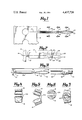
- FIG. 1 is a side elevational view of a formed flexible pin of a plurality, attached to a strip of material used as a base for forming said pins;
- FIG. 2 is a side elevational view of an unformed flexible pin attached to a strip of material that is scored for breaking;
- FIG. 3 is a side elevational view of a formed flexible pin and its mating receptacle used therewith;
- FIG. 4 is a sectional view of the fingers of said pin taken along lines 4--4 of FIG. 1;
- FIG. 5 is a sectional view of the fingers of said pin formed with a larger but usable diameter
- FIG. 6 is a sectional view of the fingers of said pin taken along lines 6--6 of FIG. 1;
- FIG. 7 is a sectional view of the pin barrel taken along lines 7--7 of FIG. 1.
- FIG. 2 there is shown a band of beryllium copper material 10 that includes a plurality of struts 11 to which is secured a first portion 12 that is rolled into a barrel shape 12A.
- a score line 13 is impressed in the material to approximately one-half the thickness to aid in breaking the strut 11 from barrel 12A.
- Extending parallel to a longitudinal axis 14 are a pair of fingers 15 and 16 that are cantilevered and integrally formed from the first portion 12.
- the overall length from the score line to the tip end of fingers 15 and 16 is 0.308 inches. Fingers 15 and 16 have reduced width portions 17 and 18 that appear 0.190 inches from the score line 13.
- the reduced width is located at a point of minimal bending stress allowing clearance between the edge of the fingers 15 and 16, and the interior of the mating tubular member, allowing increased accommodation of nonparallelism of the axis of the barrel and the mating tubular member.
- the tip ends 20 and 21 of fingers 15 and 16 are formed with a 0.005 inch radius where the remaining portion of the tip is formed with a 0.030 inch radius.
- each of fingers 15 and 16 extending from the reduced portion to the tip ends 20 and 21, are a pair of coined edges 22 and 23 on finger 15 and 23 and 24 on finger 16.
- the transverse projection of the fingers extend 0.005 inches beyond the edge of the diameter of barrel 12A and the separation between the two fingers or leaves is 0.004 inches as disclosed in FIG. 6.
- the pin structure is formed to be inserted into a tubular receiving connector member 30 that has an inside diameter of 0.0225 inches and is shown broken away in FIG. 3.
- the connecting wire 31 is crimped at 32, to complete the connection for use with the flexible pin members.
- the most desirable condition obtainable is that the tips of the fingers touch each other to give the greatest flexibility of fingers 15 and 16 and to assure the easiest insertion into the tubular receiving connector member 30.
- barrel 12A may be curved until it assumes a circular cross section having a diameter of 0.215 inches such as disclosed in FIG. 4.
- the pin may be desirable to have the pin with a larger radius such as disclosed in FIG. 5 where the barrel diameter is 0.0265 plus or minus 0.0005 inches.
- the lateral edges of the first band 12 are curved towards each other to form a gap 33 with the two edges.
- the minimum gap permits the diameter of barrel 12A to have a diameter of 0.020 inches and the fingers 15 and 16 assume the configuration disclosed in FIG. 7.
- the entire reel of pins is gold plated to produce the necessary electrical characteristics.
- the electrical characteristics of the pin are enhanced through the coined edges that have at least the corners which are formed in a typically smooth configuration to permit all four edges to contact the inner barrel of tubular receiving connector member 30 and produce a smooth wiping electrical contact which is also achieved through flexing of blades 15 and 16. That is, blades 15 and 16 maybe somewhat askew with each other and through the reduced width portions 17 and 18, the fingers are brought into what may be generally considered to be parallel alignment as shown in FIG. 4.
- the pins may take on various forms in being secured to a printed circuit board or may become a portion of a connector in which a plurality of the pins are secured side by side.
Landscapes
- Manufacturing Of Electrical Connectors (AREA)
Abstract
Description
Claims (12)
Priority Applications (1)
| Application Number | Priority Date | Filing Date | Title |
|---|---|---|---|
| US06/387,969 US4437726A (en) | 1982-06-14 | 1982-06-14 | Flexible pin |
Applications Claiming Priority (1)
| Application Number | Priority Date | Filing Date | Title |
|---|---|---|---|
| US06/387,969 US4437726A (en) | 1982-06-14 | 1982-06-14 | Flexible pin |
Publications (1)
| Publication Number | Publication Date |
|---|---|
| US4437726A true US4437726A (en) | 1984-03-20 |
Family
ID=23532071
Family Applications (1)
| Application Number | Title | Priority Date | Filing Date |
|---|---|---|---|
| US06/387,969 Expired - Lifetime US4437726A (en) | 1982-06-14 | 1982-06-14 | Flexible pin |
Country Status (1)
| Country | Link |
|---|---|
| US (1) | US4437726A (en) |
Cited By (18)
| Publication number | Priority date | Publication date | Assignee | Title |
|---|---|---|---|---|
| US4687279A (en) * | 1985-12-20 | 1987-08-18 | Storm Products Co. | High frequency coaxial connector adaptor |
| US4797113A (en) * | 1987-02-05 | 1989-01-10 | Lambert Roger T | Board to board flexible pin |
| US4820207A (en) * | 1985-12-31 | 1989-04-11 | Labinal Components And Systems, Inc. | Electrical contact |
| US4842536A (en) * | 1987-02-09 | 1989-06-27 | Nivarox-Far S.A. | Miniature connector and method for the manufacture thereof |
| US5004438A (en) * | 1990-07-03 | 1991-04-02 | Precision Interconnect Corporation | Flexible pin type contact |
| WO1996037012A1 (en) * | 1995-05-15 | 1996-11-21 | Berg Technology, Inc. | Electrical connector including means for terminating wires |
| US6000973A (en) * | 1992-01-22 | 1999-12-14 | Berg Technology, Inc. | Electrical connector with plug contact elements of plate material |
| EP1182733A3 (en) * | 2000-08-18 | 2002-06-26 | Tyco Electronics AMP GmbH | Electrical contact system |
| US20040093927A1 (en) * | 2002-11-18 | 2004-05-20 | The Boeing Company | Adjustable corrugation apparatus and method |
| US20080040926A1 (en) * | 2006-08-15 | 2008-02-21 | The Boeing Company | Apparatus and Method for Forming Corrugated Members |
| US20090029580A1 (en) * | 2007-07-26 | 2009-01-29 | Northrop Grumman Systems Corporation | Helical contact connector system |
| US20090197479A1 (en) * | 2008-01-31 | 2009-08-06 | Fci Americas Technology, Inc. | Electrical Connector |
| DE202010008456U1 (en) * | 2010-09-06 | 2011-12-07 | Walter Söhner GmbH & Co. KG | connector |
| EP2475047A2 (en) | 2011-01-07 | 2012-07-11 | Hypertronics Corporation | Electrical contact with embedded wiring |
| US9285119B2 (en) | 2010-06-30 | 2016-03-15 | Sabaf S.P.A. | Electrical connection for connecting a thermocouple to the magnet assembly of a safety cock for gas supply |
| US20170086673A1 (en) * | 2015-09-30 | 2017-03-30 | Signal Solutions, Llc | Stimulation System Based on Mechanical Vibration for Modification and Characterization of Sleep and Behavior in Rodents |
| USD787448S1 (en) | 2014-08-18 | 2017-05-23 | Interlemo Holding S.A. | Electrical connector |
| USD863221S1 (en) | 2015-09-04 | 2019-10-15 | Interlemo Holding Sa | Illuminable female connector |
Citations (17)
| Publication number | Priority date | Publication date | Assignee | Title |
|---|---|---|---|---|
| US538423A (en) | 1895-04-30 | Electrical coupling | ||
| US2517677A (en) | 1948-03-15 | 1950-08-08 | Kjell-Berger Bo Gustaf Kjeil | Connecting plug |
| US3008118A (en) | 1959-03-25 | 1961-11-07 | Amp Inc | Plug contactor |
| US3098687A (en) | 1960-12-05 | 1963-07-23 | United Carr Fastener Corp | Electrical connector |
| US3123427A (en) | 1964-03-03 | Electrical connectors | ||
| FR1406969A (en) | 1964-06-05 | 1965-07-23 | United Carr Inc | improved element constituting an electrical contact |
| US3252127A (en) | 1963-10-03 | 1966-05-17 | United Carr Inc | Plug contact |
| US3286671A (en) | 1963-06-10 | 1966-11-22 | Amp Inc | Pin and socket connector assembly |
| US3545080A (en) | 1967-05-16 | 1970-12-08 | Amp Inc | Method of making resilient pins |
| US3581272A (en) | 1968-12-23 | 1971-05-25 | Bunker Ramo | Miniature connector |
| US3693140A (en) | 1970-01-20 | 1972-09-19 | Bunker Ramo | Miniature electrical connector contacts |
| US3697931A (en) | 1971-01-04 | 1972-10-10 | Illinois Tool Works | Electrical plug contact |
| US3786558A (en) | 1971-11-16 | 1974-01-22 | L Mccarthy | Method of making a hollow electrical contact |
| US3808588A (en) | 1972-02-16 | 1974-04-30 | Electrix Corp | Terminal clip for circuit boards |
| US3924921A (en) | 1971-12-23 | 1975-12-09 | New Twist Connector Corp | Electrical-pin-and-socket connector |
| US4168878A (en) | 1978-05-22 | 1979-09-25 | Amp Incorporated | Pin and socket type electrical terminals |
| US4169654A (en) | 1977-05-19 | 1979-10-02 | General Motors Corporation | Pin type electrical contact terminal |
-
1982
- 1982-06-14 US US06/387,969 patent/US4437726A/en not_active Expired - Lifetime
Patent Citations (17)
| Publication number | Priority date | Publication date | Assignee | Title |
|---|---|---|---|---|
| US538423A (en) | 1895-04-30 | Electrical coupling | ||
| US3123427A (en) | 1964-03-03 | Electrical connectors | ||
| US2517677A (en) | 1948-03-15 | 1950-08-08 | Kjell-Berger Bo Gustaf Kjeil | Connecting plug |
| US3008118A (en) | 1959-03-25 | 1961-11-07 | Amp Inc | Plug contactor |
| US3098687A (en) | 1960-12-05 | 1963-07-23 | United Carr Fastener Corp | Electrical connector |
| US3286671A (en) | 1963-06-10 | 1966-11-22 | Amp Inc | Pin and socket connector assembly |
| US3252127A (en) | 1963-10-03 | 1966-05-17 | United Carr Inc | Plug contact |
| FR1406969A (en) | 1964-06-05 | 1965-07-23 | United Carr Inc | improved element constituting an electrical contact |
| US3545080A (en) | 1967-05-16 | 1970-12-08 | Amp Inc | Method of making resilient pins |
| US3581272A (en) | 1968-12-23 | 1971-05-25 | Bunker Ramo | Miniature connector |
| US3693140A (en) | 1970-01-20 | 1972-09-19 | Bunker Ramo | Miniature electrical connector contacts |
| US3697931A (en) | 1971-01-04 | 1972-10-10 | Illinois Tool Works | Electrical plug contact |
| US3786558A (en) | 1971-11-16 | 1974-01-22 | L Mccarthy | Method of making a hollow electrical contact |
| US3924921A (en) | 1971-12-23 | 1975-12-09 | New Twist Connector Corp | Electrical-pin-and-socket connector |
| US3808588A (en) | 1972-02-16 | 1974-04-30 | Electrix Corp | Terminal clip for circuit boards |
| US4169654A (en) | 1977-05-19 | 1979-10-02 | General Motors Corporation | Pin type electrical contact terminal |
| US4168878A (en) | 1978-05-22 | 1979-09-25 | Amp Incorporated | Pin and socket type electrical terminals |
Cited By (29)
| Publication number | Priority date | Publication date | Assignee | Title |
|---|---|---|---|---|
| US4687279A (en) * | 1985-12-20 | 1987-08-18 | Storm Products Co. | High frequency coaxial connector adaptor |
| US4820207A (en) * | 1985-12-31 | 1989-04-11 | Labinal Components And Systems, Inc. | Electrical contact |
| US4797113A (en) * | 1987-02-05 | 1989-01-10 | Lambert Roger T | Board to board flexible pin |
| US4842536A (en) * | 1987-02-09 | 1989-06-27 | Nivarox-Far S.A. | Miniature connector and method for the manufacture thereof |
| US5004438A (en) * | 1990-07-03 | 1991-04-02 | Precision Interconnect Corporation | Flexible pin type contact |
| US6000973A (en) * | 1992-01-22 | 1999-12-14 | Berg Technology, Inc. | Electrical connector with plug contact elements of plate material |
| US5639258A (en) * | 1995-05-15 | 1997-06-17 | Berg Technology, Inc. | Electrical connector including means for terminating wires |
| US5746620A (en) * | 1995-05-15 | 1998-05-05 | Berg Technology, Inc. | Electrical connector including means for terminating wires |
| WO1996037012A1 (en) * | 1995-05-15 | 1996-11-21 | Berg Technology, Inc. | Electrical connector including means for terminating wires |
| EP1182733A3 (en) * | 2000-08-18 | 2002-06-26 | Tyco Electronics AMP GmbH | Electrical contact system |
| US20040093927A1 (en) * | 2002-11-18 | 2004-05-20 | The Boeing Company | Adjustable corrugation apparatus and method |
| US6834525B2 (en) * | 2002-11-18 | 2004-12-28 | The Boeing Company | Adjustable corrugation apparatus and method |
| US20080040926A1 (en) * | 2006-08-15 | 2008-02-21 | The Boeing Company | Apparatus and Method for Forming Corrugated Members |
| US7642481B2 (en) | 2006-08-15 | 2010-01-05 | The Boeing Company | Apparatus and method for forming corrugated members |
| US7517226B2 (en) | 2007-07-26 | 2009-04-14 | Eli Kawam | Helical contact connector system |
| US20090029580A1 (en) * | 2007-07-26 | 2009-01-29 | Northrop Grumman Systems Corporation | Helical contact connector system |
| US20090197479A1 (en) * | 2008-01-31 | 2009-08-06 | Fci Americas Technology, Inc. | Electrical Connector |
| US7845992B2 (en) | 2008-01-31 | 2010-12-07 | Fci Americas Technology, Inc. | Electrical connector with contact arm preloading |
| EP2589117B1 (en) * | 2010-06-30 | 2017-11-08 | SABAF S.p.A. | Electrical connection for connecting a thermocouple to the magnet assembly of a safety cock for gas supply" |
| US9285119B2 (en) | 2010-06-30 | 2016-03-15 | Sabaf S.P.A. | Electrical connection for connecting a thermocouple to the magnet assembly of a safety cock for gas supply |
| DE202010008456U1 (en) * | 2010-09-06 | 2011-12-07 | Walter Söhner GmbH & Co. KG | connector |
| EP2475047A3 (en) * | 2011-01-07 | 2014-10-29 | Hypertronics Corporation | Electrical contact with embedded wiring |
| US8636551B2 (en) | 2011-01-07 | 2014-01-28 | Hypertronics Corporation | Electrical contact with embedded wiring |
| EP2475047A2 (en) | 2011-01-07 | 2012-07-11 | Hypertronics Corporation | Electrical contact with embedded wiring |
| USD810029S1 (en) | 2014-02-18 | 2018-02-13 | Interlemo Holding Sa | Electrical connector |
| USD787448S1 (en) | 2014-08-18 | 2017-05-23 | Interlemo Holding S.A. | Electrical connector |
| USD863221S1 (en) | 2015-09-04 | 2019-10-15 | Interlemo Holding Sa | Illuminable female connector |
| US20170086673A1 (en) * | 2015-09-30 | 2017-03-30 | Signal Solutions, Llc | Stimulation System Based on Mechanical Vibration for Modification and Characterization of Sleep and Behavior in Rodents |
| US9681808B2 (en) * | 2015-09-30 | 2017-06-20 | Signal Solutions, Llc | Stimulation system based on mechanical vibration for modification and characterization of sleep and behavior in rodents |
Similar Documents
| Publication | Publication Date | Title |
|---|---|---|
| US4437726A (en) | Flexible pin | |
| US3363224A (en) | Electrical connector | |
| US7074096B2 (en) | Electrical contact with plural arch-shaped elements | |
| US5588884A (en) | Stamped and formed contacts for a power connector | |
| US4591230A (en) | Electrical connector receptacle | |
| JP5831509B2 (en) | Press-fit connector terminal and manufacturing method thereof | |
| EP0505646A2 (en) | Electrical contact system with cantilever mating beams | |
| US4857019A (en) | Terminal pin with s-shaped complaint portion | |
| US3781770A (en) | Circuit board socket | |
| US3233208A (en) | Contact for direct reception of printed circuit board | |
| JP2562926B2 (en) | Flexible push-fit pin | |
| US2866172A (en) | Electrical connector | |
| US2674725A (en) | Electrical connector | |
| JP2876146B2 (en) | Receptacle type contact | |
| JPS6217967A (en) | Electric contact and manufacture thereof | |
| US4753617A (en) | Electrical device having flexible electrical contacts | |
| US4712850A (en) | Terminal strip with attached support and method of manufacture | |
| KR101520976B1 (en) | contact carrier | |
| JP6996117B2 (en) | Press-fit terminal | |
| US3012221A (en) | Electrical socket contacts | |
| DE4416888C1 (en) | Contact element for electrical plug connector | |
| JP5979279B2 (en) | Press-fit connector terminal and manufacturing method thereof | |
| EP0261839A2 (en) | Spring contact electrical connector assembly | |
| GB1576387A (en) | Box terminal for use in telecommunications systems and the like | |
| JPS588112B2 (en) | Contact spring for connector |
Legal Events
| Date | Code | Title | Description |
|---|---|---|---|
| AS | Assignment |
Owner name: OMNETICS, INC., 917 19TH AVE., NE, MINNEAPOLIS, MN Free format text: ASSIGNMENT OF ASSIGNORS INTEREST.;ASSIGNOR:LAMBERT, ROGER T.;REEL/FRAME:004022/0478 Effective date: 19820610 Owner name: OMNETICS, INC., A CORP OF, MINNESOTA Free format text: ASSIGNMENT OF ASSIGNORS INTEREST;ASSIGNOR:LAMBERT, ROGER T.;REEL/FRAME:004022/0478 Effective date: 19820610 |
|
| STCF | Information on status: patent grant |
Free format text: PATENTED CASE |
|
| MAFP | Maintenance fee payment |
Free format text: PAYMENT OF MAINTENANCE FEE, 4TH YEAR, PL 96-517 (ORIGINAL EVENT CODE: M170); ENTITY STATUS OF PATENT OWNER: SMALL ENTITY Year of fee payment: 4 |
|
| MAFP | Maintenance fee payment |
Free format text: PAYMENT OF MAINTENANCE FEE, 8TH YEAR, PL 96-517 (ORIGINAL EVENT CODE: M171); ENTITY STATUS OF PATENT OWNER: SMALL ENTITY Year of fee payment: 8 |
|
| FEPP | Fee payment procedure |
Free format text: MAINTENANCE FEE REMINDER MAILED (ORIGINAL EVENT CODE: REM.); ENTITY STATUS OF PATENT OWNER: SMALL ENTITY |
|
| FEPP | Fee payment procedure |
Free format text: SURCHARGE FOR LATE PAYMENT, SMALL ENTITY (ORIGINAL EVENT CODE: M286); ENTITY STATUS OF PATENT OWNER: SMALL ENTITY |
|
| MAFP | Maintenance fee payment |
Free format text: PAYMENT OF MAINTENANCE FEE, 12TH YR, SMALL ENTITY (ORIGINAL EVENT CODE: M285); ENTITY STATUS OF PATENT OWNER: SMALL ENTITY Year of fee payment: 12 |