WO2018179701A1 - 気体圧縮機 - Google Patents
気体圧縮機 Download PDFInfo
- Publication number
- WO2018179701A1 WO2018179701A1 PCT/JP2018/001358 JP2018001358W WO2018179701A1 WO 2018179701 A1 WO2018179701 A1 WO 2018179701A1 JP 2018001358 W JP2018001358 W JP 2018001358W WO 2018179701 A1 WO2018179701 A1 WO 2018179701A1
- Authority
- WO
- WIPO (PCT)
- Prior art keywords
- peripheral surface
- curve
- rotor
- closest
- stroke
- Prior art date
- Legal status (The legal status is an assumption and is not a legal conclusion. Google has not performed a legal analysis and makes no representation as to the accuracy of the status listed.)
- Ceased
Links
Images

Classifications
-
- F—MECHANICAL ENGINEERING; LIGHTING; HEATING; WEAPONS; BLASTING
- F04—POSITIVE - DISPLACEMENT MACHINES FOR LIQUIDS; PUMPS FOR LIQUIDS OR ELASTIC FLUIDS
- F04C—ROTARY-PISTON, OR OSCILLATING-PISTON, POSITIVE-DISPLACEMENT MACHINES FOR LIQUIDS; ROTARY-PISTON, OR OSCILLATING-PISTON, POSITIVE-DISPLACEMENT PUMPS
- F04C18/00—Rotary-piston pumps specially adapted for elastic fluids
- F04C18/30—Rotary-piston pumps specially adapted for elastic fluids having the characteristics covered by two or more of groups F04C18/02, F04C18/08, F04C18/22, F04C18/24, F04C18/48, or having the characteristics covered by one of these groups together with some other type of movement between co-operating members
- F04C18/34—Rotary-piston pumps specially adapted for elastic fluids having the characteristics covered by two or more of groups F04C18/02, F04C18/08, F04C18/22, F04C18/24, F04C18/48, or having the characteristics covered by one of these groups together with some other type of movement between co-operating members having the movement defined in group F04C18/08 or F04C18/22 and relative reciprocation between the co-operating members
- F04C18/344—Rotary-piston pumps specially adapted for elastic fluids having the characteristics covered by two or more of groups F04C18/02, F04C18/08, F04C18/22, F04C18/24, F04C18/48, or having the characteristics covered by one of these groups together with some other type of movement between co-operating members having the movement defined in group F04C18/08 or F04C18/22 and relative reciprocation between the co-operating members with vanes reciprocating with respect to the inner member
Definitions
- the present invention relates to a gas compressor.
- vane rotary type gas compressor of an air conditioning system mounted on a vehicle or the like.
- This vane rotary type gas compressor has a so-called two-cycle type in which the steps of gas suction, compression, and discharge are performed twice during one rotation of the rotor.
- the cross-sectional contour shape of the inner peripheral surface of the cylinder is an ellipse (see, for example, Patent Document 1).
- the compression period is short because the gas is sucked, compressed, and discharged while the rotor rotates 180 degrees, and the pressure in the compression chamber becomes higher than the specified pressure. Is likely to occur. Therefore, in order to lengthen the compression stroke, the elliptical shape of the cross-sectional contour shape of the inner peripheral surface of the cylinder is sucked into the position of the major axis of the ellipse (the remotest part where the inner peripheral surface of the cylinder and the outer peripheral surface of the rotor are farthest apart). The shape may be biased toward the stroke side (upstream side in the rotational direction of the rotor).
- the position of the major axis is biased to the suction stroke side in this way, the position of the ellipse minor axis (the closest part where the inner peripheral surface of the cylinder is closest to the outer peripheral surface of the rotor) is downstream in the rotational direction of the rotor.
- the vane protruding from the rotor cannot follow the change in the contour shape and the tip of the vane is easily separated from the inner peripheral surface of the cylinder.
- the position of the major axis cannot be largely biased toward the suction stroke, and the effect of preventing or suppressing overcompression cannot be sufficiently exhibited.
- This invention is made in view of the said situation, Comprising: It aims at providing the gas compressor which can prevent that a vane cannot fully follow, preventing or suppressing overcompression.
- the present invention is provided in a cylinder having an inner peripheral surface, a rotor disposed on the inner side surrounded by the inner peripheral surface, rotating about a central axis, and having an outer peripheral surface having a circular cross-sectional contour shape, and the rotor.
- a plurality of vanes that project from the outer peripheral surface in accordance with the rotation of the rotor and that move while contacting the inner peripheral surface to form a suction stroke, a compression stroke, and a discharge stroke.
- the cross-sectional contour shape of the peripheral surface is (1) having a closest part closest to the rotor and a remotest part farthest from the rotor; (2) The farthest portion is formed biased upstream in the rotational direction of the rotor such that the compression stroke and the discharge stroke are longer than the suction stroke. (3) At least a portion from the closest portion corresponding to the suction stroke to the remotest portion on the downstream side in the rotation direction is kept in contact with the tip of the vane due to the vane jumping out as the rotor rotates. A first curve and a second curve different from the first curve, wherein a distance from the central axis is changed to smoothly connect an end of the first curve and the remotest part, respectively It is a gas compressor containing.
- the vane it is possible to prevent the vane from being able to follow up while preventing or suppressing overcompression.
- FIG. 1 is a cross-sectional view of a compression mechanism 60 in a compressor 100 according to an embodiment of the present invention.
- the compressor 100 is of the vane rotary type, and the cross-sectional contour shape of the inner peripheral surface 41 of the cylinder 40 with which the tip 58a of the vane 58 protruding from the rotor 50 contacts is downstream of the rotation direction R of the rotor 50 from the closest portion.
- the most remote part is formed by two different curves.
- the compressor 100 is configured as a part of an air conditioning system (hereinafter simply referred to as an air conditioning system) mounted on a vehicle, and cools together with other components such as a condenser, an expansion valve, and an evaporator. It is provided on the circulation path of the medium.
- the compressor 100 compresses the refrigerant gas G (gas) as a gaseous cooling medium taken from the evaporator of the air conditioning system, and supplies the compressed refrigerant gas G to the condenser of the air conditioning system.
- the compressor 100 includes a compression mechanism 60 that sucks low-pressure refrigerant gas G into the housing, compresses the drawn refrigerant gas G to high pressure, and discharges the refrigerant gas G to the outside. .
- the compression mechanism unit 60 includes a rotating shaft 59, a rotor 50, a vane 58, a cylinder 40, and two side blocks 20 and 30.
- the cylinder 40 has an inner peripheral surface 41 having a contour shape (cross-sectional contour shape) in the cross section shown in FIG.
- the rotor 50 is formed in a cylindrical shape having an outer peripheral surface with a circular cross-sectional profile.
- the rotor 50 is disposed on the inner side surrounded by the inner peripheral surface 41 of the cylinder 40.
- the rotor 50 rotates in the clockwise direction R in FIG. 1 around the central axis C integrally with the rotary shaft 59 fitted in the center thereof.
- the vane 58 is provided on the rotor 50 so as to protrude from the outer peripheral surface 51.
- a plurality of vanes 58 are provided at equal angular intervals around the central axis C (for example, five at an angle of 72 degrees).
- Each vane 58 is disposed inside a vane groove formed in the rotor 50.
- Each vane 58 receives a load directed outward from the outer peripheral surface 51 of the rotor 50 due to the centrifugal force generated by the rotation of the rotor 50 and the hydraulic pressure acting on the back pressure chamber 52 formed on the innermost side of the vane groove. It is provided so that it can protrude from the outer peripheral surface 51 along the vane groove.
- the two side blocks 20 and 30 are arranged so as to cover the end faces of the cylinder 40 and the end face of the rotor 50 so as to cover these end faces, and the rotary shaft 59 protruding from each end face of the rotor 50 is rotatable. I support it.
- One side block (front side block) 20 covers the end surface of the compressor 100 near the suction chamber (not shown) through which the low-pressure refrigerant gas G introduced from the outside is guided, and the other side block (rear side block).
- (Block) 30 covers an end face on the side close to a discharge chamber (not shown) through which high-pressure refrigerant gas G discharged to the outside is guided.
- the rear side block 30 is arrange
- the front side block 20 is arranged on the front side of the cylinder 40 and the rotor 50, so that it is not visually recognized as an entity, but is indicated by parenthesized symbols to indicate that it exists on the front side. ing.
- the inside of the compression mechanism portion 60 includes two cylinders having a substantially crescent-shaped cross section by the inner peripheral surface 41 of the cylinder 40, the outer peripheral surface 51 of the rotor 50, and the inner side surfaces of both side blocks 20, 30. Chambers 53 and 54 are formed. These two cylinder chambers 53 and 54 are formed to be rotationally symmetric with respect to the central axis C.
- the cylinder chambers 53 and 54 are partitioned into a plurality of spaces by vanes 58 protruding from the outer peripheral surface 51 of the rotor 50. That is, the rotor 50 rotates in the clockwise direction R while the tip 58a of the protruding vane 58 is pressed against and contacted with the inner peripheral surface 41 of the cylinder 40.
- Each space partitioned by the vanes 58 is a compression chamber 55 whose volume changes as the rotor 50 rotates in the clockwise direction R.
- the compression chamber 55 increases in volume to form a suction stroke for sucking low-pressure refrigerant gas G into the interior, and decreases in volume to form a compression stroke in which the refrigerant gas G is compressed to high pressure. Then, the discharge volume is further reduced to approach zero, and a discharge stroke for discharging the refrigerant gas G to the outside is formed.
- the refrigerant gas G is sucked into the compression chamber 55 through the suction port 21 formed in the front side block 20 and the suction passage 48 formed in the cylinder 40 in the suction stroke.
- the refrigerant gas G compressed to a high pressure in the compression chamber 55 is discharged to the outside through a discharge port (not shown) formed in the cylinder 40.
- the compression mechanism 60 uses the in-vehicle engine as a power source, or if the compressor 100 itself has an electric motor, the electric motor as the power source, and the rotation shaft 59 around the central axis C
- the rotor 50 is rotated by rotating in the clockwise direction R of 1.
- the compression chamber 55 formed in the upper cylinder chamber 53 and the compression chamber 55 formed in the lower cylinder chamber 54 in FIG. 1 are a series of suction stroke, compression stroke, and discharge stroke, respectively. Cycle.
- each compression chamber 55 performs a series of cycles of a suction stroke, a compression stroke, and a discharge stroke twice (one time on the cylinder chamber 53 side and once on the cylinder chamber 54 side) while the rotor 50 rotates once. ) Is configured to do.
- the two suction strokes, the two compression strokes, and the two discharge strokes are set in a rotationally symmetric range that is shifted by a rotation angle of 180 degrees with respect to the central axis C of the rotation shaft 59.
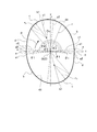
- FIG. 2 is a diagram showing only the cross-sectional contour shape of the inner peripheral surface 41 of FIG. Next, details of the cross-sectional contour shape of the inner peripheral surface 41 of the cylinder 40 of the compressor 100 will be described with reference to FIG.
- the cross-sectional contour shape of the inner peripheral surface 41 is set as follows. First, as shown in FIG. 2, the central axis C is the origin O (0, 0) of the xy orthogonal coordinate system, and the cross-sectional contour shape of the inner peripheral surface 41 is represented by a distance r from the origin O in the xy orthogonal coordinates.
- the x-axis is, for example, the circumference at the closest portion (the portion a formed over a predetermined angular range 2 ⁇ ⁇ 1) where the inner peripheral surface 41 of the cylinder 40 and the outer peripheral surface 51 of the rotor 50 are closest. It was set as a straight line connecting the center along the direction and the central axis C.
- ⁇ be the angle around the origin O when going from the positive direction of the x-axis to the positive direction of the y-axis (the direction opposite to the rotational direction R of the rotor 50).
- the cross-sectional contour shape in the positive range of the y-axis and the cross-sectional contour shape in the negative range of the y-axis are rotationally symmetric with respect to the origin O.
- the curve of the equation (1) is an equation showing an ellipse having a minor axis P and a major axis P + Q.
- S in Expression (1) is a positive number smaller than 1
- the portion a1 where the short axis x1 intersects the inner peripheral surface 41 is a part of the above-mentioned closest portion, and the portion b1 where the long axis y1 intersects the inner peripheral surface 41 is the inner peripheral surface 41 of the cylinder 40. Is the most remote part farthest from the outer peripheral surface 51 of the rotor 50. Unlike the closest portion, the remotest portion is not formed over a predetermined angle range, but only two points that are symmetrical to each other on the inner peripheral surface 41.
- the major axis y1 of the ellipse is the angular position of the minor axis x1 of the ellipse of Expression (1).
- the major axis y1 is not orthogonal to the minor axis x1, but is biased upstream in the rotational direction R of the rotor 50.
- the long axis y1 is biased in the negative direction of the x axis, the farthest portion is biased upstream in the rotational direction R of the rotor 50 so that the compression stroke and the discharge stroke are longer than the suction stroke. Is formed.
- the condition of S in the above formula (1) is not limited to S ⁇ 1. That is, in the formula (1), S ⁇ 90 / (90 ⁇ 1) may be used. Even under this condition, the elliptical long axis y1 of the formula (1) is an angular position that is biased toward the negative direction of the x-axis, that is, upstream of the rotational direction R of the rotor 50 (the suction stroke side). The compression stroke and the discharge stroke are biased toward the upstream side in the rotation direction R of the rotor 50 so that the compression stroke and the discharge stroke are longer than the suction stroke.
- the curve of the equation (2) is an equation showing an ellipse having a minor axis of P and a major axis of P + T.
- the short axis x2 and the long axis y2 are orthogonal to each other.
- a portion a2 where the short axis x2 intersects the inner peripheral surface 41 is a part of the closest portion described above.
- T in Formula (2) is a positive number larger than Q in Formula (1)
- the major axis (P + T) of the elliptic shape represented by Formula (2) is larger than the major axis (P + Q) of the elliptical shape represented by Formula (1).
- the portion d of the angle range ( ⁇ 3 ⁇ ⁇ ⁇ ⁇ 4) does not include the portion of the major axis y2.
- This circular arc has a center Oc on the elliptical long axis y1 of the formula (1) forming the part b of the angular range ( ⁇ 1 ⁇ ⁇ ⁇ ⁇ 2), and is formed with a radius r A ( ⁇ P + Q). ing.
- the slope of the tangent line coincides with the portion d forming the elliptical arc of the formula (2) so as to be smoothly connected.
- the cross-sectional contour shape of the inner peripheral surface 41 shown in FIG. 2 is defined by the following (i) to (v).
- the portion c of the angular range ( ⁇ 2 ⁇ ⁇ ⁇ ⁇ 3) is on the elliptical long axis y1 represented by the equation (1) (the central axis C and the remote part (the long axis y1 is the inner peripheral surface 41). It is formed by an arc of a radius r a with a center Oc to the straight line) which connects the portions b1) and crossing (one example of the second curve).
- the oval shape of the formula (2) that defines the portion d in the angle range ( ⁇ 3 ⁇ ⁇ ⁇ ⁇ 4) has a shape in which the tip 58a of the vane 58 keeps in contact with the inner peripheral surface 41 due to the vane 58 jumping out as the rotor 50 rotates. It has become.
- the vane 58 projects by receiving the centrifugal force generated by the rotation of the rotor 50 and the hydraulic pressure acting on the back pressure chamber 52.
- the distance r from the origin O which is the cross-sectional contour shape of the inner peripheral surface 41 of the cylinder 40, is a shape that increases sharply with respect to the rotation angle of the rotor 50, the protrusion of the vane 58 cannot sufficiently follow.
- the tip 58a of the vane 58 may be separated from the inner peripheral surface 41. In particular, immediately after the start of rotation from the state in which the rotor 50 is stopped, the centrifugal force and the hydraulic pressure acting on the back pressure chamber 52 are small, so that the protrusion of the vane 58 is a severe condition.
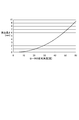
- FIG. 3 is a graph showing an example of a correspondence relationship between the rotation angle [degree] of the rotor 50 and the protrusion length [mm] of the vane 58 (no constraint by the inner peripheral surface 41) under such severe conditions. .
- the rotation angle of the rotor 50 on the horizontal axis in the graph is 0 [degrees] when the tip 58a of the vane 58 is aligned with the negative direction of the x axis shown in FIG. 2, and the rotation in the rotation direction R proceeds. It is assumed that the rotation angle increases in the direction. Therefore, the rotation angle of the rotor 50 in FIG. 3 differs from the angle ⁇ shown in FIG. 2 in a reference position and an increasing direction.
- the vane The protrusion length of 58 is relatively small. Therefore, in this portion d, the tip 58 a of the vane 58 tends to be easily separated from the inner peripheral surface 41. Accordingly, the range (r) of the formula (2) that defines this portion d can be followed by the range in which the protrusion length of the vane 58 at the rotation angle of the corresponding rotor 50 can be followed, that is, the tip 58a is kept in contact with the inner peripheral surface 41. 2) is set.
- the cross-sectional contour shape of the inner peripheral surface 41 is an ellipse as a whole, and the short diameter (nearest portion) having the shortest distance r from the origin O is expressed by the equation (1).
- the state of arcs such as parts a and e And formed over a predetermined angle range.
- the longest diameter (remote portion) having the longest distance r from the origin O is the portion where the elliptical long axis y1 defined by the equation (1) intersects (in the cross-sectional contour shape). 2 points) Only b1.
- the portion in the angular range from the portion a2 at the end of the closest portion to the portion b1 that is the most remote portion on the downstream side in the rotation direction R of the rotor 50 is expressed by the formula (2 ) Of an elliptical arc (part d) and an arc (part c).
- the compressor 100 of the present embodiment configured as described above, it is possible to prevent the vane 58 from being able to follow up while preventing or suppressing overcompression in the compression chamber 55. That is, for the portion b corresponding to the compression stroke, by applying the elliptical arc of the formula (1) in which the long axis y1 is biased toward the suction stroke, the compression stroke is reduced as compared with the non-biased one. Can be long. When the compression stroke is lengthened, the volume change rate is relaxed, and the occurrence of overcompression can be suppressed.
- the parts d and c corresponding to the suction stroke are defined by an elliptical arc of the same formula (2) as the part b, the protrusion of the vane 58 is caused. It becomes difficult to follow.
- the parts d and c corresponding to the suction stroke are different curves from the part b corresponding to the compression stroke, and another expression (2) in the range that the vane 58 can follow. Therefore, even when the protrusion of the vane 58 is severe, it is possible to prevent or suppress the tip 58a of the vane 58 from being separated from the inner peripheral surface 41 of the cylinder 40.
- the elliptical arc of the suction stroke equation (2) and the compression stroke equation (1) The elliptical arc is not smoothly connected or difficult to connect smoothly.
- the portion d on the side closer to the minor axis is set as an elliptical arc of another formula (2) within a range in which the vane 58 can follow.
- the distance r from the origin O changes according to the angle ⁇ in both the part b and the part c, and is connected to the long axis y1. Since the portion b1 is the most remote portion, the portion where the tip 58a of the vane 58 contacts is compared with the portion where the distance r from the origin O is constant regardless of the angle ⁇ in a certain angular range including the major axis y1. This also has the effect of suppressing the acceleration of wear caused by the movement of a certain portion and the contact of certain portions.
- the arc in the portion c it therefore the center Oc is on the long axis y1, that while smoothly connecting the portions b and portions c to connect on the long axis y1, to adjust the radius r A of the arc Therefore, it is easy to perform adjustment for smoothly connecting the part d.
- the radius r A is shorter than the major axis (P + Q) of the long axis y1 (part b), preventing the protruding length of the vanes 58 at the portion c suddenly increases or Can be suppressed.
- the elliptical arc of the formula (2) which is an example of the first curve corresponding to the suction stroke portion d, is changed from the major axis y1 to the rotation direction R of the rotor 50.
- the tip 58a of the vane 58 in the portion d is difficult to separate because it is formed by an arc of another elliptical shape different from the elliptical shape of the formula (1) that forms the cross-sectional contour shape up to the short axis x1 directed toward the downstream side. It is easy to select the shape inner peripheral surface 41.
- the compressor 100 applies an elliptical arc as the first curve and an arc as the second curve with respect to the cross-sectional contour shape of the inner peripheral surface 41 of the cylinder 40.
- the gas compressor is not limited to this form. That is, the first curve in the contour shape of the inner peripheral surface of the cylinder according to the present invention may be another curve that is not an elliptical arc that protrudes outward, and the second curve is also outward. It may be a curve other than the convex arc.
- a curve forming a section b having a cross-sectional contour shape from the remotest part b1 to the closest part a1 corresponding to the compression stroke and the discharge process has the longest remote part b1 as the major axis and the closest part a1. It is assumed that it is defined by a specific first elliptic formula (for example, a formula in which constants B1 and B2 are set to appropriate values in the following formula (3)) having a minor axis.
- r A + B1 ⁇ sin n ⁇ B2 ⁇ ( ⁇ 1) ⁇ (where ⁇ 1 may be 0 (zero)) (3)
- the closest part a2 has a short diameter
- the remotest part b1 has a long diameter
- the remotest part b1 has a specific first
- the first curve is
- the portion d may be a curve formed inside the cylinder chambers 53 and 54 (the dimension from the central axis C is short).
- r A + B1 ⁇ sin n ⁇ B3 ⁇ ( ⁇ 180 + ⁇ 1) ⁇ (where ⁇ 1 may be 0 (zero)) (4)
- the constant B1 in the elliptic equation (4) corresponding to the first curve is the constant in the specific second elliptic equation (4). If the constant B3 in the elliptic equation (4) corresponding to the first curve is larger than B1 and greater than the constant B3 in the specific second elliptic equation (4), the first curve Compared to the curve defined by the elliptic equation (4) of FIG. 2, in the portion d, it is possible to make the curve closer to the graph formed inside the cylinder chambers 53 and 54 and shown in FIG.
- the constant B1 in the elliptic equation (4) corresponding to the first curve is the constant in the specific second elliptic equation (4).
- the constant B3 in the elliptic equation (4) corresponding to the first curve is smaller than B1 and smaller than the constant B3 in the specific second elliptic equation (4), the first curve also has a specific first Compared with the curve defined by the elliptic formula (4) of FIG. 2, the curve can be formed in the portion d inside the cylinder chambers 53 and 54 and closer to the graph of FIG.
- the second curve besides a circular arc, for example, a cubic Bezier curve or a curve defined by a cubic equation that protrudes outward can be applied.
- the compressor 100 according to the present embodiment is such that the cross-sectional contour shape of the portion in the angle range from the closest part to the remotest part downstream in the rotational direction R of the rotor 50 is formed by two different curves.
- the cross-sectional contour shape of the portion in this angular range is not limited to those formed by two curves, and those formed by three curves or four or more curves. It may be formed.
- the inner peripheral surface 41 is formed with a large number of curved surfaces, the manufacturing effort increases, so that it is preferable that the number is small from the viewpoint of manufacturing cost.
- the compressor 100 of the present embodiment has a single elliptical cross-sectional contour shape in a portion (compression stroke and discharge stroke) in an angle range from the most remote portion to the closest portion downstream in the rotation direction R of the rotor 50.
- the gas compressor according to the present invention is formed in a shape, the cross-sectional contour shape of the portion in this angular range is not limited to that in this embodiment, and is formed by two or more curves. May be.
Landscapes
- Engineering & Computer Science (AREA)
- Mechanical Engineering (AREA)
- General Engineering & Computer Science (AREA)
- Rotary Pumps (AREA)
- Applications Or Details Of Rotary Compressors (AREA)
Abstract
気体圧縮機において、過圧縮を防止又は抑制しつつ、ベーンが追従しきれなくなるのを防止するために、コンプレッサ(100)は、シリンダ(40)の内周面(41)の断面輪郭形状が、 (1)ロータ(50)の外周面(51)に最も近い最近接部(部分(a))と、外周面(51)から最も離れた最遠隔部(部分(b1))とを有し、 (2)最遠隔部は、圧縮行程及び吐出行程が吸入行程よりも長くなるように、ロータ(50)の回転方向(R)の上流側に偏って形成され、 (3)最近接部から回転方向(R)の下流側の最遠隔部までの角度範囲の部分(d),(c)が、ベーン(58)の先端(58a)が接し続ける楕円形の弧(第1の曲線)と、中心軸(C)からの距離(r)が変化して、その楕円形の弧の端と最遠隔部とを滑らかに接続する円弧(第2の曲線)とを含む。
Description
本発明は、気体圧縮機に関する。
車両等に搭載されている空気調和システム(以下、空調システムという。)の気体圧縮機として、ベーンロータリ形式のものがある。このベーンロータリ形式の気体圧縮機は、ロータの1回転の間に、気体の吸入、圧縮及び吐出の行程を2回行う、いわゆる2サイクルのものがある。このような2サイクルのベーンロータリ形式の気体圧縮機は、シリンダの内周面の断面輪郭形状が楕円形で形成されている(例えば、特許文献1参照)。
ところで、2サイクルの気体圧縮機は、ロータが180[度]回転する間に気体の吸入、圧縮及び吐出の行程を行うため圧縮期間が短く、圧縮室内の圧力が規定圧力よりも高くなる過圧縮が起こり易い。そこで、圧縮行程を長くするため、シリンダの内周面の断面輪郭形状の楕円形状を、楕円の長径の位置(シリンダの内周面とロータの外周面とが最も離れた最遠隔部)を吸入行程の側(ロータの回転方向の上流側)に偏らせた形状にすることがある。
しかし、このように長径の位置を吸入行程側に偏らせるにしたがって、楕円の短径の位置(シリンダの内周面がロータの外周面に最も近い最近接部)からロータの回転方向の下流側の長径の位置までの輪郭形状の変化が大きくなって、ロータの回転に伴ってロータから突出するベーンがその輪郭形状の変化に追従しきれなくなり、ベーンの先端がシリンダの内周面から離れ易くなるという問題がある。このため、長径の位置を、吸入行程の側に大きく偏らせることができず、過圧縮を防止又は抑制する効果を十分に発揮させることができない。
本発明は上記事情に鑑みなされたものであって、過圧縮を防止又は抑制しつつ、ベーンが追従しきれなくなるのを防止することができる気体圧縮機を提供することを目的とする。
本発明は、内周面を有するシリンダと、前記内周面で囲まれた内側に配置され、中心軸回りに回転する、断面輪郭形状が円形の外周面を有するロータと、前記ロータに設けられ、前記ロータの回転にしたがって、前記外周面から突出し、先端が前記内周面に接しながら移動することで、吸入行程と圧縮行程及び吐出行程とを形成する複数のベーンと、を備え、前記内周面の断面輪郭形状は、
(1)前記ロータに最も近い最近接部と、前記ロータから最も離れた最遠隔部とを有し、
(2)前記最遠隔部は、前記圧縮行程及び前記吐出行程が前記吸入行程よりも長くなるように、前記ロータの回転方向の上流側に偏って形成され、
(3)前記吸入行程に対応した前記最近接部から前記回転方向の下流側の前記最遠隔部までの部分が、少なくとも、前記ロータの回転に伴う前記ベーンの飛び出しにより前記ベーンの先端が接し続ける第1の曲線と、前記中心軸からの距離が変化して、前記第1の曲線の端と前記最遠隔部とをそれぞれ滑らかに接続する、前記第1の曲線とは異なる第2の曲線とを含んでいる気体圧縮機である。
(1)前記ロータに最も近い最近接部と、前記ロータから最も離れた最遠隔部とを有し、
(2)前記最遠隔部は、前記圧縮行程及び前記吐出行程が前記吸入行程よりも長くなるように、前記ロータの回転方向の上流側に偏って形成され、
(3)前記吸入行程に対応した前記最近接部から前記回転方向の下流側の前記最遠隔部までの部分が、少なくとも、前記ロータの回転に伴う前記ベーンの飛び出しにより前記ベーンの先端が接し続ける第1の曲線と、前記中心軸からの距離が変化して、前記第1の曲線の端と前記最遠隔部とをそれぞれ滑らかに接続する、前記第1の曲線とは異なる第2の曲線とを含んでいる気体圧縮機である。
本発明に係る気体圧縮機によれば、過圧縮を防止又は抑制しつつ、ベーンが追従しきれなくなるのを防止することができる。
以下、本発明に係る気体圧縮機の実施形態について、図面を参照して説明する。図1は本発明の一実施形態であるコンプレッサ100における圧縮機構部60の断面図である。
<概要>
コンプレッサ100は、ベーンロータリ形式のもので、ロータ50から突出するベーン58の先端58aが接するシリンダ40の内周面41の断面輪郭形状について、最近接部からロータ50の回転方向Rの下流側の最遠隔部までを互いに異なる2つの曲線で形成したものである。
コンプレッサ100は、ベーンロータリ形式のもので、ロータ50から突出するベーン58の先端58aが接するシリンダ40の内周面41の断面輪郭形状について、最近接部からロータ50の回転方向Rの下流側の最遠隔部までを互いに異なる2つの曲線で形成したものである。
<コンプレッサ>
コンプレッサ100は、車両に搭載された空気調和システム(以下、単に空調システムという。)の一部として構成され、この空調システムの他の構成要素である凝縮器、膨張弁、蒸発器等とともに、冷却媒体の循環経路上に設けられている。コンプレッサ100は、空調システムの蒸発器から取り入れた気体状の冷却媒体としての冷媒ガスG(気体)を圧縮し、この圧縮された冷媒ガスGを空調システムの凝縮器に供給する。コンプレッサ100は、ハウジングの内部に、図1に示すように、低圧の冷媒ガスGを内部に吸入し、吸入した冷媒ガスGを高圧に圧縮して外部に吐出する圧縮機構部60を備えている。
コンプレッサ100は、車両に搭載された空気調和システム(以下、単に空調システムという。)の一部として構成され、この空調システムの他の構成要素である凝縮器、膨張弁、蒸発器等とともに、冷却媒体の循環経路上に設けられている。コンプレッサ100は、空調システムの蒸発器から取り入れた気体状の冷却媒体としての冷媒ガスG(気体)を圧縮し、この圧縮された冷媒ガスGを空調システムの凝縮器に供給する。コンプレッサ100は、ハウジングの内部に、図1に示すように、低圧の冷媒ガスGを内部に吸入し、吸入した冷媒ガスGを高圧に圧縮して外部に吐出する圧縮機構部60を備えている。
圧縮機構部60は、図1に示すように、回転軸59と、ロータ50と、ベーン58と、シリンダ40と、2つのサイドブロック20,30と、を備えている。シリンダ40は、図1に示した断面における輪郭形状(断面輪郭形状)の内周面41を有している。ロータ50は、断面輪郭形状が円形の外周面を有する円柱状に形成されている。ロータ50は、シリンダ40の内周面41で囲まれた内側に配置されている。ロータ50は、その中心部に嵌め合わされた回転軸59と一体的に、中心軸C回りに、図1において時計回り方向Rに回転する。
ベーン58は、ロータ50に、外周面51から突出可能に設けられている。ベーン58は、中心軸C回りの等角度間隔で複数枚(例えば角度72[度]間隔で5枚)設けられている。各ベーン58はロータ50に形成されたベーン溝の内部に配置されている。各ベーン58は、ロータ50の回転によって生じる遠心力と、ベーン溝の最内側に形成された背圧室52に作用する油圧とにより、ロータ50の外周面51から外側に向かう荷重を受けることで、ベーン溝に沿って、外周面51から突出可能に設けられている。
2つのサイドブロック20,30は、シリンダ40の端面とロータ50の端面とに跨って、これらの各端面を覆うように配置され、また、ロータ50の各端面から突出した回転軸59を回転自在に支持している。一方のサイドブロック(フロントサイドブロック)20は、外部から導入された低圧の冷媒ガスGが導かれる、コンプレッサ100の吸入室(図示せず)に近い側の端面を覆い、他方のサイドブロック(リアサイドブロック)30は、外部に吐出された高圧の冷媒ガスGが導かれる吐出室(図示せず)に近い側の端面を覆っている。
なお、図1において、リアサイドブロック30は、シリンダ40及びロータ50の奥側に配置されているため、実体として視認される。一方、フロントサイドブロック20は、図1において、シリンダ40及びロータ50の手前側に配置されているため、実体として視認されないが、手前側に存在することを示すためにカッコ付の符号で表記している。
このように、圧縮機構部60の内部は、シリンダ40の内周面41とロータ50の外周面51と両サイドブロック20,30の内側面とによって、断面輪郭が概略三日月状である2つのシリンダ室53,54を形成している。これら2つのシリンダ室53,54は、中心軸Cに対して回転対称に形成されている。
各シリンダ室53,54は、ロータ50の外周面51から突出したベーン58によって複数の空間に仕切られる。すなわち、突出したベーン58の先端58aがシリンダ40の内周面41に押し付けられて接しながら、ロータ50が時計回り方向Rに回転する。そして、ベーン58によって仕切られた各空間は、ロータ50の時計回り方向Rへの回転にしたがって、容積が変化する圧縮室55である。
圧縮室55は、ロータ50の回転にしたがって、容積が増大して低圧の冷媒ガスGを内部に吸入する吸入行程を形成し、容積が減少して冷媒ガスGを高圧に圧縮する圧縮行程を形成し、容積がさらに減少してゼロに近づいて冷媒ガスGを外部に吐出する吐出行程を形成している。
なお、冷媒ガスGは、吸入行程で、フロントサイドブロック20に形成された吸入口21及びシリンダ40に形成された吸入通路48を通じて、圧縮室55の内部に吸入される。一方、圧縮室55で高圧に圧縮された冷媒ガスGは、シリンダ40に形成された吐出口(図示せず)を通じて外部に吐出される。
このように、圧縮機構部60は、車載のエンジンを動力源として、又はコンプレッサ100自体が電動モータを有するものであればその電動モータを動力源として、回転軸59を中心軸C回りに、図1の時計回り方向Rに回転させることで、ロータ50を回転させる。そして、圧縮機構部60は、図1の上側のシリンダ室53に形成された圧縮室55と下側のシリンダ室54に形成された圧縮室55とがそれぞれ吸入行程、圧縮行程、吐出行程という一連のサイクルを行う。
したがって、各圧縮室55は、ロータ50が1回転する間に、吸入行程、圧縮行程、吐出行程という一連のサイクルを2回(シリンダ室53の側で1回、シリンダ室54の側で1回)行うように構成されている。2つの吸入行程、2つの圧縮行程、2つの吐出行程は、回転軸59の中心軸Cを挟んで回転角度180[度]だけずれた回転対称の範囲に設定されている。
<シリンダの内周面の断面輪郭形状>
図2は、図1の内周面41の断面輪郭形状だけを示した図である。次に、このコンプレッサ100のシリンダ40の内周面41の断面輪郭形状の詳細について、図2を参照して説明する。
図2は、図1の内周面41の断面輪郭形状だけを示した図である。次に、このコンプレッサ100のシリンダ40の内周面41の断面輪郭形状の詳細について、図2を参照して説明する。
内周面41の断面輪郭形状は、以下のように設定されている。まず、図2に示すように、中心軸Cをxy直交座標系の原点O(0,0)として、内周面41の断面輪郭形状をxy直交座標における原点Oからの距離rで表す。ここで、x軸は、例えば、シリンダ40の内周面41とロータ50の外周面51とが最も近い最近接部(所定の角度範囲2×θ1に亘って形成されている部分a)における周方向に沿った中央と中心軸Cとを結ぶ直線として設定した。
また、x軸の正方向からy軸の正方向に向かうとき(ロータ50の回転方向Rとは反対の向き)の原点O回りの角度をθとする。y軸の正の範囲における断面輪郭形状とy軸の負の範囲における断面輪郭形状は原点Oに対して回転対称である。
ここで、図2に示すように、断面輪郭形状のうちx軸の正方向(θ=0)と交差する部分を含む所定の角度範囲(0≦θ[度]≦θ1;θ1は90[度]未満の角度で、例えば10[度]以下の角度)の部分aは最近接部であり、原点Oを中心とする半径Pの円弧(r=P)で形成されている。なお、x軸の正方向に対して角度θが負となる所定の角度範囲(-θ1≦θ≦0)の部分eも、同様に最近接部であり、原点Oを中心とする半径Pの円弧(r=P)で形成されている。
y軸の正の範囲における断面輪郭形状とy軸の負の範囲における断面輪郭形状は原点Oに対して回転対称であるため、x軸の正方向に対して角度θが負となる所定の角度範囲(-90<-θ1≦θ≦0)の部分eと回転対称となる角度範囲(90<θ4≦θ≦180;ただし、θ4=180-θ1)の部分eについても、原点Oを中心とする半径Pの円弧(r=P)で形成されている。
また、断面輪郭形状のうち、x軸の正方向からの角度θが、角度θ1以上の角度範囲(θ1≦θ≦θ2)の部分bは、一例として下記式(1)の距離rで規定される曲線で形成されている。
r=P+Qsin2{S(θ-θ1)}(ただし、0<P,0<Q,0<S<1) (1)
r=P+Qsin2{S(θ-θ1)}(ただし、0<P,0<Q,0<S<1) (1)
この式(1)の曲線は、短径がP、長径がP+Qの楕円形を示す式である。そして、式(1)のSが1より小さい正数であるため、式(1)が表す楕円形は、短軸x1がx軸の正方向から角度θ1だけy軸の正方向(θ=90[度])に傾いた角度位置にあり、長軸y1がy軸の正方向から角度(θ1+90/S-90)[度]だけx軸の負方向(θ=180)に傾いた角度位置にある。
なお、短軸x1が内周面41と交差する部分a1は、前述した最近接部の一部であり、長軸y1が内周面41と交差する部分b1は、シリンダ40の内周面41がロータ50の外周面51から最も離れた最遠隔部である。最遠隔部は最近接部とは異なり、所定の角度範囲に亘って形成されたものではなく、内周面41において互いに対称となる2点のみである。
ここで、S<1の場合、角度(90/S)[度]は角度90[度]より大きいため、この楕円形の長軸y1は式(1)の楕円形の短軸x1の角度位置(θ=θ1)に直交する方向(θ=θ1+90)よりも、x軸の負方向すなわちロータ50の回転方向Rの上流側(吸入行程側)に角度Δθ(=90/S-90)だけ偏った角度位置となっている。つまり、長軸y1は、短軸x1と直交せずに、ロータ50の回転方向Rの上流側に偏っている。なお、長軸y1がx軸の負方向に偏っていることで、最遠隔部は、圧縮行程及び吐出行程が吸入行程よりも長くなるように、ロータ50の回転方向Rの上流側に偏って形成されている。
上述した式(1)におけるSの条件は、S<1に限定されるものではない。すなわち、式(1)において、S<90/(90-θ1)でもよい。この条件であっても、式(1)の楕円形の長軸y1はx軸の負方向すなわちロータ50の回転方向Rの上流側(吸入行程側)に偏った角度位置となり、最遠隔部は、圧縮行程及び吐出行程が吸入行程よりも長くなるように、ロータ50の回転方向Rの上流側に偏って形成される。
また、式(1)の楕円形は、短軸x1の角度位置(θ=θ1)において、角度範囲(0≦θ≦θ1)において円弧を形成している部分aと、接線の傾きが一致して滑らかに接続するように設定されている。
なお、角度範囲(θ1≦θ≦θ2)の部分bの端である角度θ=θ2の位置は、式(1)の楕円形の長軸y1の角度位置として設定されている(θ2=θ1+90/S)。したがって、角度範囲(θ1≦θ≦θ2)の部分bは、ロータ50の回転方向Rに対応させると、式(1)の断面輪郭形状で長軸y1の角度位置(θ=θ2)から短軸x1の角度位置(θ=θ1)に向かう断面輪郭形状であるため、圧縮室55の容積が小さくなる範囲であり、圧縮室55の圧縮行程及び吐出行程に対応している。
断面輪郭形状のうち、x軸の負方向からy軸の正方向に向かう所定の角度範囲(θ4≦θ≦180)の部分eについては、前述したとおり、原点Oを中心とする半径Pの円弧(r=P)で形成されている。したがって、この部分eも最近接部である。
断面輪郭形状のうち、x軸の正方向からの角度θが、式(1)の楕円形の長軸y1の角度位置(θ=θ2)よりもx軸の負方向の側の位置である角度θ3以上の所定の角度範囲(θ2<θ3≦θ≦θ4<180)の部分dは、一例として下記式(2)の、距離rで規定される曲線(第1の曲線の一例)で形成されている。
r=P+Tsin2(θ+θ4)(ただし、Q<T)(2)
r=P+Tsin2(θ+θ4)(ただし、Q<T)(2)
この式(2)の曲線は、短径がP、長径がP+Tの楕円形を示す式であり、この楕円形の短軸x2はx軸の負方向(θ=180)からy軸の正方向(θ=90)に角度θ1(=180-θ4)だけ傾いた角度位置にあり、式(2)の楕円形の長軸y2はy軸の正方向からx軸の正方向に角度θ1だけ傾いた角度位置(θ=90-θ1)方向に存在する。したがって、角度範囲(θ3≦θ≦θ4)の部分dは、短軸x2と長軸y2とは直交する。なお、短軸x2が内周面41と交差する部分a2は、前述した最近接部の一部である。
式(2)のTは式(1)のQより大きい正数であるため、式(2)が表す楕円形状の長径(P+T)は式(1)が表す楕円形状の長径(P+Q)よりも長いが、角度範囲(θ3≦θ≦θ4)の部分dには、長軸y2の部分を含まない。
角度範囲(θ3≦θ≦θ4)の部分dは、ロータ50の回転方向Rに対応させると、式(2)の断面輪郭形状で短軸x2の角度位置(θ=θ4)から長軸y2の角度位置に向かう断面輪郭形状であるため、圧縮室55の容積が大きくなる範囲であり、圧縮室55の吸入行程に対応している。
また、式(2)の楕円形は、短軸x2の角度位置(θ=θ4)において、角度範囲(θ4≦θ≦180)において円弧を形成している部分eと、接線の傾きが一致して滑らかに接続するように設定されている。
断面輪郭形状のうち、x軸の正方向からの角度θが、式(1)の楕円形の部分bの長軸y1の角度位置(θ=θ2)から式(2)の楕円形の部分dの端の角度位置(θ=θ3)までの所定の角度範囲(θ2≦θ≦θ3)の部分cは、円弧(第2の曲線の一例)で形成されている。この円弧は、角度範囲(θ1≦θ≦θ2)の部分bを形成している式(1)の楕円形の長軸y1上に中心Ocを有し、半径rA(<P+Q)で形成されている。
また、この円弧は、角度位置(θ=θ2)において、式(1)の楕円形の弧を形成している部分bと接線の傾きが一致するように滑らかに接続され、角度位置(θ=θ3)において式(2)の楕円形の弧を形成している部分dと接線の傾きが一致して滑らかに接続されるように設定されている。
以上をまとめると、図2に示した内周面41の断面輪郭形状は、以下の(i)~(v)で規定される。
(i)角度範囲(0≦θ≦θ1)の部分aは、原点Oを中心とする半径Pの円弧(r=P)で形成されている。この部分aは、全体が最近接部であり、式(1)の楕円形の短軸x1と交差する部分(角度位置(θ=θ1)の部分)を含んでいる。
(ii)角度範囲(θ1≦θ≦θ2)の部分bは、式(1)で表される楕円形の、短軸x1が交差する部分a1から、y軸よりもロータ50の回転方向Rの上流側に偏って形成された長軸y1が交差する部分b1までの弧で形成されている。角度位置(θ=θ1)では部分aと滑らかに接続されている。
(iii)角度範囲(θ4≦θ≦180)の部分eは、全体が最近接部であり、原点Oを中心とする半径Pの円弧(r=P)で形成されている。この部分eは、後述する式(2)の楕円形の短軸x2と交差する部分(角度位置(θ=θ4)の部分)a2を含んでいる。
(iv)角度範囲(θ2≦θ≦θ3)の部分cは、式(1)で表される楕円形の長軸y1上(中心軸Cと最遠隔部(長軸y1が内周面41と交差する部分b1)とを結んだ直線上)に中心Ocを有する半径rAの円弧(第2の曲線の一例)で形成されている。この円弧は、原点O(中心軸C)からの距離rが変化する曲線であり、角度位置(θ=θ2)では部分bと滑らかに接続され、角度位置(θ=θ3)では部分dと滑らかに接続されている。
(v)角度範囲(θ3≦θ≦θ4)の部分dは、式(2)で表される楕円形の、短軸x2が交差する部分からの弧(第1の曲線の一例)で形成されている。角度位置(θ=θ4)では部分eと滑らかに接続されている。
(i)角度範囲(0≦θ≦θ1)の部分aは、原点Oを中心とする半径Pの円弧(r=P)で形成されている。この部分aは、全体が最近接部であり、式(1)の楕円形の短軸x1と交差する部分(角度位置(θ=θ1)の部分)を含んでいる。
(ii)角度範囲(θ1≦θ≦θ2)の部分bは、式(1)で表される楕円形の、短軸x1が交差する部分a1から、y軸よりもロータ50の回転方向Rの上流側に偏って形成された長軸y1が交差する部分b1までの弧で形成されている。角度位置(θ=θ1)では部分aと滑らかに接続されている。
(iii)角度範囲(θ4≦θ≦180)の部分eは、全体が最近接部であり、原点Oを中心とする半径Pの円弧(r=P)で形成されている。この部分eは、後述する式(2)の楕円形の短軸x2と交差する部分(角度位置(θ=θ4)の部分)a2を含んでいる。
(iv)角度範囲(θ2≦θ≦θ3)の部分cは、式(1)で表される楕円形の長軸y1上(中心軸Cと最遠隔部(長軸y1が内周面41と交差する部分b1)とを結んだ直線上)に中心Ocを有する半径rAの円弧(第2の曲線の一例)で形成されている。この円弧は、原点O(中心軸C)からの距離rが変化する曲線であり、角度位置(θ=θ2)では部分bと滑らかに接続され、角度位置(θ=θ3)では部分dと滑らかに接続されている。
(v)角度範囲(θ3≦θ≦θ4)の部分dは、式(2)で表される楕円形の、短軸x2が交差する部分からの弧(第1の曲線の一例)で形成されている。角度位置(θ=θ4)では部分eと滑らかに接続されている。
角度範囲(θ3≦θ≦θ4)の部分dを規定する式(2)の楕円形は、ロータ50の回転に伴うベーン58の飛び出しによりベーン58の先端58aが内周面41に接し続ける形状となっている。
ベーン58は、前述したように、ロータ50の回転によって生じる遠心力と背圧室52に作用する油圧とを受けて突出する。しかし、シリンダ40の内周面41の断面輪郭形状である原点Oからの距離rが、ロータ50の回転角度に対して急激に大きくなる形状であると、ベーン58の突出が十分に追従できず、ベーン58の先端58aが内周面41から離れてしまうことが起こり得る。特に、ロータ50が停止している状態から回転を開始する起動直後は、遠心力も背圧室52に作用する油圧も小さいため、ベーン58の突出には厳しい条件となる。
図3は、このような厳しい条件での、ロータ50の回転角度[度]とベーン58の突出長さ[mm](内周面41による拘束無し)との対応関係の一例を示すグラフである。なお、グラフにおける横軸のロータ50の回転角度は、ベーン58の先端58aを図2に示したx軸の負方向に一致させた状態を0[度]とし、回転方向Rへの回転が進む方向で回転角度が増大するものとする。したがって、図3におけるロータ50の回転角度は、図2に示した角度θとは、基準となる位置及び増大する向きが異なる。
図3に示すように、ロータ50の回転角度が小さい範囲、すなわち、ベーン58が、吸入行程に対応した、図2の角度範囲(θ3≦θ≦θ4)の部分dを通過するときは、ベーン58の突出長さが比較的少ない。したがって、この部分dにおいては、ベーン58の先端58aが内周面41から離れ易い傾向がある。したがって、この部分dを規定する式(2)のrを、対応するロータ50の回転角度におけるベーン58の突出長さで追従できる範囲つまり先端58aが内周面41に接し続けるように、式(2)が設定されている。
また、本実施形態のコンプレッサ100は、内周面41の断面輪郭形状が、全体としては、楕円形であり、原点Oからの距離rが最も短い短径(最近接部)は、式(1)で規定される楕円形の短軸x1が交差する部分a1や式(2)で規定される楕円形の短軸x2が交差する部分a2だけでなく、部分a,eというように円弧の状態で所定の角度範囲に亘って形成されている。一方、本実施形態のコンプレッサ100は、原点Oからの距離rが最も長い長径(最遠隔部)は、式(1)で規定される楕円形の長軸y1が交差する部分(断面輪郭形状において2点)b1だけである。
そして、内周面41の断面輪郭形状のうち、最近接部の端の部分a2からロータ50の回転方向Rの下流側の最遠隔部である部分b1までの角度範囲の部分が、式(2)の楕円形の弧(部分d)と円弧(部分c)との2つの曲線を含んで形成されている。
以上のように構成された本実施形態のコンプレッサ100によれば、圧縮室55での過圧縮を防止又は抑制しつつ、ベーン58が追従しきれなくなるのを防止することができる。すなわち、圧縮行程に対応した部分bについて、長軸y1を吸入行程の方に偏らせた式(1)の楕円形の弧を適用したことで、偏らせていないものに比べて、圧縮行程を長くすることができる。圧縮行程を長くすると、体積変化速度が緩和されて、過圧縮の発生を抑制することができる。
また、部分bの長軸y1を吸入側に偏らせた場合、吸入行程に対応した部分d,cを、部分bと同じ式(2)の楕円形の弧で規定すると、ベーン58の突出が追従し難くなる。しかし、本実施形態のコンプレッサ100は、吸入行程に対応した部分d,cを、圧縮行程に対応した部分bとは異なる曲線であって、ベーン58の追従し得る範囲の別の式(2)の楕円形の弧で規定しているため、ベーン58の突出が厳しい条件においても、ベーン58の先端58aがシリンダ40の内周面41から離れるのを防止又は抑制することができる。
さらに、吸入行程に対応した部分d,cを、圧縮行程に対応した部分bとは異なる曲線に設定すると、この吸入行程の式(2)の楕円形の弧と圧縮行程の式(1)の楕円形の弧とが、滑らかに接続されないか、又は滑らかに接続され難い。しかし、本実施形態のコンプレッサ100は、吸入行程に対応した部分d,cに関して、短径に近い側の部分dをベーン58の追従し得る範囲の別の式(2)の楕円形の弧とし、長径(部分b)に近い側の部分cを式(2)の楕円形の弧と式(1)の楕円形の弧とにそれぞれ滑らかに接続される別の曲線(第2の曲線)の一例である円弧としたことで、ベーン58の追従性を確保しつつ、ベーン58の急激な挙動変化を防止又は抑制することができる。
また、本実施形態のコンプレッサ100によれば、内周面41の断面輪郭形状のうち、部分bも部分cも角度θに応じて原点Oからの距離rが変化し、長軸y1に接続される部分b1だけが最遠隔部となるため、長軸y1を含む一定の角度範囲において角度θに拘わらず原点Oからの距離rが一定となるものに比べて、ベーン58の先端58aの接する部分が移動し、一定の部分が接触し続けることで生じる摩耗の促進を抑制する効果もある。
なお、部分cにおける円弧は、その中心Ocが長軸y1上にあるため、長軸y1上で接続する部分bと部分cとを滑らかに接続しつつ、その円弧の半径rAを調整することにより、部分dと滑らかに接続するための調整を行い易い。また、部分cにおける円弧は、その半径rAが、長軸y1(部分b)の長径(P+Q)よりも短いため、部分cでのベーン58の突出長さが急激に増大するのを防止又は抑制することができる。
また、本実施形態のコンプレッサ100によれば、吸入行程の部分dに対応した第1の曲線の一例である式(2)の楕円形の弧を、長軸y1からロータ50の回転方向Rの下流側に向けた短軸x1までの断面輪郭形状を形成する式(1)の楕円形とは異なる別の楕円形の弧で形成しているため、部分dにおけるベーン58の先端58aが離れ難い形状の内周面41を選定し易い。
本実施形態のコンプレッサ100は、シリンダ40の内周面41の断面輪郭形状に関して、第1の曲線として楕円形の弧、第2の曲線として円弧をそれぞれ適用したものであるが、本発明に係る気体圧縮機は、この形態に限定されるものではない。すなわち、本発明におけるシリンダの内周面の輪郭形状における第1の曲線は、外側に凸となる楕円形の弧ではない他の曲線であってもよく、また、第2の曲線も、外側に凸となる円弧以外の他の曲線であってもよい。
具体的には、圧縮行程及び吐出行程に対応した最遠隔部b1から最近接部a1までの断面輪郭形状の部分bを形成する曲線が、最遠隔部b1を長径とし、かつ最近接部a1を短径とする特定の第1の楕円式(例えば、下記式(3)において定数B1,B2を適当な値に設定した式)で定義されているものとする。
r=A+B1×sinn{B2×(θ-θ1)}(ただし、θ1は0(ゼロ)でもよい)(3)
r=A+B1×sinn{B2×(θ-θ1)}(ただし、θ1は0(ゼロ)でもよい)(3)
このとき、吸入行程に対応した最近接部a2から最遠隔部b1までを、最近接部a2を短径とし、かつ最遠隔部b1を長径とするとともに、最遠隔部b1において特定の第1の楕円式(式(3))で定義された曲線と滑らかに接続する、特定の第2の楕円式(例えば、次下記式(4))で定義された曲線に対して、第1の曲線は、部分dにおいては、シリンダ室53,54の内側(中心軸Cからの寸法が短い)に形成される曲線であればよい。
r=A+B1×sinn{B3×(θ-180+θ1)}(ただし、θ1は0(ゼロ)でもよい)(4)
r=A+B1×sinn{B3×(θ-180+θ1)}(ただし、θ1は0(ゼロ)でもよい)(4)
つまり、第1の曲線を特定の第2の楕円式(4)で定義したとき、第1の曲線に対応した楕円式(4)における定数B1が特定の第2の楕円式(4)における定数B1よりも大きく、かつ、第1の曲線に対応した楕円式(4)おける定数B3が特定の第2の楕円式(4)における定数B3よりも大きい場合は、第1の曲線は特定の第2の楕円式(4)で定義された曲線に比べて、部分dにおいて、シリンダ室53,54の内側に形成され、かつ図3に示したグラフに、より近い曲線とすることができる。
また、第1の曲線を特定の第2の楕円式(4)で定義したとき、第1の曲線に対応した楕円式(4)における定数B1が特定の第2の楕円式(4)における定数B1よりも小さく、かつ、第1の曲線に対応した楕円式(4)おける定数B3が特定の第2の楕円式(4)における定数B3よりも小さい場合も、第1の曲線は特定の第2の楕円式(4)で定義された曲線に比べて、部分dにおいて、シリンダ室53,54の内側に形成され、かつ図3のグラフにより近い曲線とすることができる。
第2の曲線としては、円弧の他として、例えば、外側に凸となる三次ベジェ曲線又は三次方程式で定義される曲線も適用することができる。
また、本実施形態のコンプレッサ100は、最近接部からロータ50の回転方向Rの下流側の最遠隔部までの角度範囲の部分の断面輪郭形状を、互いに異なる2つの曲線で形成したものであるが、本発明に係る気体圧縮機は、この角度範囲の部分の断面輪郭形状は、2つの曲線で形成されるものに限定されず、3つの曲線で形成したものや、4つ以上の曲線で形成したものであってもよい。ただし、内周面41が、多数の曲面で形成されると、製造の労力が増大するため、製造コストの観点では少数であるほうが好ましい。
また、本実施形態のコンプレッサ100は、最遠隔部からロータ50の回転方向Rの下流側の最近接部までの角度範囲の部分(圧縮行程及び吐出行程)の断面輪郭形状を、単一の楕円形で形成したものであるが、本発明に係る気体圧縮機は、この角度範囲の部分の断面輪郭形状は、この実施形態のものに限定されず、2つ以上の曲線で形成したものであってもよい。
本出願は、2017年3月27日に日本国特許庁に出願された特願2017-061747及び2017年12月22日に日本国特許庁に出願された特願2017-246693に基づいて優先権を主張し、その全ての開示は完全に本明細書で参照により組み込まれる。
Claims (6)
- 内周面を有するシリンダと、
前記内周面で囲まれた内側に配置され、中心軸回りに回転する、断面輪郭形状が円形の外周面を有するロータと、
前記ロータに設けられ、前記ロータの回転にしたがって、前記外周面から突出し、先端が前記内周面に接しながら移動することで、吸入行程と圧縮行程及び吐出行程とを形成する複数のベーンと、を備え、
前記内周面の断面輪郭形状は、
(1)前記外周面に最も近い最近接部と、前記外周面から最も離れた最遠隔部とを有し、
(2)前記最遠隔部は、前記圧縮行程及び前記吐出行程が前記吸入行程よりも長くなるように、前記ロータの回転方向の上流側に偏って形成され、
(3)前記吸入行程に対応した前記最近接部から前記回転方向の下流側の前記最遠隔部までが、少なくとも、前記ロータの回転に伴う前記ベーンの飛び出しにより前記ベーンの先端が接し続ける第1の曲線と、前記中心軸からの距離が変化して、前記第1の曲線の端と前記最遠隔部とをそれぞれ滑らかに接続する、前記第1の曲線とは異なる第2の曲線とを含んでいる気体圧縮機。 - 前記第1の曲線は、前記最遠隔部から前記ロータの回転方向の下流側の前記最近接部までの前記断面輪郭形状を形成する曲線とは異なる楕円形の弧である請求項1に記載の気体圧縮機。
- 前記圧縮行程及び前記吐出行程に対応した前記最遠隔部から前記最近接部までの前記断面輪郭形状を形成する曲線が、前記最遠隔部を長径とし、かつ前記最近接部を短径とする特定の第1の楕円式で定義され、
前記吸入行程に対応した前記最近接部から前記最遠隔部までを、前記最近接部を短径とし、かつ前記最遠隔部を長径とするとともに、前記最遠隔部において前記特定の第1の楕円式で定義された曲線と滑らかに接続する、特定の第2の楕円式で定義された曲線に対して、前記第1の曲線は、シリンダ室の内側に形成されている請求項1又は2に記載の気体圧縮機。 - 前記第2の曲線は円弧である請求項1から3のうちいずれか1項に記載の気体圧縮機。
- 前記円弧は、中心が前記中心軸と前記最遠隔部とを結んだ直線上に設定されている請求項4に記載の気体圧縮機。
- 前記第2の曲線は三次ベジェ曲線である請求項1から3のうちいずれか1項に記載の気体圧縮機。
Priority Applications (1)
| Application Number | Priority Date | Filing Date | Title |
|---|---|---|---|
| CN201880022624.XA CN110546385B (zh) | 2017-03-27 | 2018-01-18 | 气体压缩机 |
Applications Claiming Priority (4)
| Application Number | Priority Date | Filing Date | Title |
|---|---|---|---|
| JP2017-061747 | 2017-03-27 | ||
| JP2017061747 | 2017-03-27 | ||
| JP2017-246693 | 2017-12-22 | ||
| JP2017246693A JP6479951B2 (ja) | 2017-03-27 | 2017-12-22 | 気体圧縮機 |
Publications (1)
| Publication Number | Publication Date |
|---|---|
| WO2018179701A1 true WO2018179701A1 (ja) | 2018-10-04 |
Family
ID=63674632
Family Applications (1)
| Application Number | Title | Priority Date | Filing Date |
|---|---|---|---|
| PCT/JP2018/001358 Ceased WO2018179701A1 (ja) | 2017-03-27 | 2018-01-18 | 気体圧縮機 |
Country Status (1)
| Country | Link |
|---|---|
| WO (1) | WO2018179701A1 (ja) |
Cited By (2)
| Publication number | Priority date | Publication date | Assignee | Title |
|---|---|---|---|---|
| CN111207079A (zh) * | 2020-01-10 | 2020-05-29 | 中国石油大学(华东) | 一种气缸型线不对称的两级压缩滑片式真空泵 |
| CN114810596A (zh) * | 2022-05-23 | 2022-07-29 | 常州康普瑞汽车空调有限公司 | 一种旋叶式压缩机缸体及其型线设计方法 |
Citations (6)
| Publication number | Priority date | Publication date | Assignee | Title |
|---|---|---|---|---|
| JPS6060291A (ja) * | 1983-09-08 | 1985-04-06 | Toyoda Autom Loom Works Ltd | ベ−ンの追随性の良好なベ−ン圧縮機 |
| JPS62195482A (ja) * | 1986-02-21 | 1987-08-28 | Atsugi Motor Parts Co Ltd | ベ−ン型回転圧縮機 |
| JPS63230979A (ja) * | 1987-03-19 | 1988-09-27 | Diesel Kiki Co Ltd | ベ−ン型圧縮機 |
| JPS648378A (en) * | 1987-06-30 | 1989-01-12 | Jidosha Kiki Co | Vane pump |
| JPH01163488A (ja) * | 1987-12-21 | 1989-06-27 | Seiko Seiki Co Ltd | 気体圧縮機 |
| JP2002161882A (ja) * | 2000-11-28 | 2002-06-07 | Seiko Instruments Inc | 気体圧縮機 |
-
2018
- 2018-01-18 WO PCT/JP2018/001358 patent/WO2018179701A1/ja not_active Ceased
Patent Citations (6)
| Publication number | Priority date | Publication date | Assignee | Title |
|---|---|---|---|---|
| JPS6060291A (ja) * | 1983-09-08 | 1985-04-06 | Toyoda Autom Loom Works Ltd | ベ−ンの追随性の良好なベ−ン圧縮機 |
| JPS62195482A (ja) * | 1986-02-21 | 1987-08-28 | Atsugi Motor Parts Co Ltd | ベ−ン型回転圧縮機 |
| JPS63230979A (ja) * | 1987-03-19 | 1988-09-27 | Diesel Kiki Co Ltd | ベ−ン型圧縮機 |
| JPS648378A (en) * | 1987-06-30 | 1989-01-12 | Jidosha Kiki Co | Vane pump |
| JPH01163488A (ja) * | 1987-12-21 | 1989-06-27 | Seiko Seiki Co Ltd | 気体圧縮機 |
| JP2002161882A (ja) * | 2000-11-28 | 2002-06-07 | Seiko Instruments Inc | 気体圧縮機 |
Cited By (2)
| Publication number | Priority date | Publication date | Assignee | Title |
|---|---|---|---|---|
| CN111207079A (zh) * | 2020-01-10 | 2020-05-29 | 中国石油大学(华东) | 一种气缸型线不对称的两级压缩滑片式真空泵 |
| CN114810596A (zh) * | 2022-05-23 | 2022-07-29 | 常州康普瑞汽车空调有限公司 | 一种旋叶式压缩机缸体及其型线设计方法 |
Similar Documents
| Publication | Publication Date | Title |
|---|---|---|
| US20150198161A1 (en) | Scroll type compressor | |
| WO2013172144A1 (ja) | 気体圧縮機 | |
| US7320579B2 (en) | Roots type fluid machine | |
| JPH0456155B2 (ja) | ||
| KR20190025246A (ko) | 스크롤 압축기 | |
| CN105074216B (zh) | 可变容量式叶片泵 | |
| JP6479951B2 (ja) | 気体圧縮機 | |
| JP2011052592A (ja) | 回転式圧縮機 | |
| WO2018179701A1 (ja) | 気体圧縮機 | |
| CN108953142B (zh) | 用于交通工具空调设施的涡旋式压缩机 | |
| US6257855B1 (en) | Screw fluid machine | |
| JP2008133763A (ja) | スクリュー流体機械 | |
| JPS61268894A (ja) | ベ−ン型圧縮機 | |
| KR20220077944A (ko) | 스크롤 압축기 | |
| JP2018162777A (ja) | 気体圧縮機 | |
| US12031536B2 (en) | Screw compressor and screw rotor | |
| US11493044B2 (en) | Rotary compressor with a vane discharge-sided groove and a vane suction-sided groove | |
| CN106536934A (zh) | 回转式压缩机 | |
| KR100313895B1 (ko) | 스크롤 압축기 | |
| JP2673431B2 (ja) | 気体圧縮機 | |
| EP1365153B1 (en) | Gas compressor | |
| JPH0231240B2 (ja) | ||
| CN113685352B (zh) | 滚动转子式压缩机气缸及压缩机 | |
| JP2004138056A (ja) | スクロール式流体機械 | |
| JP2008150981A (ja) | ベーンロータリー圧縮機 |
Legal Events
| Date | Code | Title | Description |
|---|---|---|---|
| 121 | Ep: the epo has been informed by wipo that ep was designated in this application |
Ref document number: 18776857 Country of ref document: EP Kind code of ref document: A1 |
|
| DPE1 | Request for preliminary examination filed after expiration of 19th month from priority date (pct application filed from 20040101) | ||
| NENP | Non-entry into the national phase |
Ref country code: DE |
|
| 122 | Ep: pct application non-entry in european phase |
Ref document number: 18776857 Country of ref document: EP Kind code of ref document: A1 |