WO2018179643A1 - ポンプ用回転羽根部材および排水ポンプ - Google Patents
ポンプ用回転羽根部材および排水ポンプ Download PDFInfo
- Publication number
- WO2018179643A1 WO2018179643A1 PCT/JP2017/046552 JP2017046552W WO2018179643A1 WO 2018179643 A1 WO2018179643 A1 WO 2018179643A1 JP 2017046552 W JP2017046552 W JP 2017046552W WO 2018179643 A1 WO2018179643 A1 WO 2018179643A1
- Authority
- WO
- WIPO (PCT)
- Prior art keywords
- plate
- diameter
- pump
- rotary blade
- blade member
- Prior art date
- Legal status (The legal status is an assumption and is not a legal conclusion. Google has not performed a legal analysis and makes no representation as to the accuracy of the status listed.)
- Ceased
Links
Images






Classifications
-
- F—MECHANICAL ENGINEERING; LIGHTING; HEATING; WEAPONS; BLASTING
- F04—POSITIVE - DISPLACEMENT MACHINES FOR LIQUIDS; PUMPS FOR LIQUIDS OR ELASTIC FLUIDS
- F04D—NON-POSITIVE-DISPLACEMENT PUMPS
- F04D1/00—Radial-flow pumps, e.g. centrifugal pumps; Helico-centrifugal pumps
- F04D1/14—Pumps raising fluids by centrifugal force within a conical rotary bowl with vertical axis
Definitions
- the present invention relates to a rotary blade member for a pump and a drainage pump.
- the drain pump is used to draw in (suction) liquid and to discharge the drawn liquid out of the pump.
- the drainage pump uses a rotary blade member for a pump for rotating and sucking liquid.
- Patent Document 1 discloses a drainage pump for draining drain water condensed by an air conditioner.
- the drainage pump described in Patent Document 1 has been filed by the applicant of the present patent application, and includes rotating blades for sucking and discharging drain water.
- the rotary vane connects a large-diameter vane, a small-diameter vane, a disk-shaped member provided between the large-diameter vane and the small-diameter vane and an opening (hole) in the center, and an outer peripheral edge of the large-diameter vane.
- a wall member is a wall member.
- the drainage pump described in Patent Document 1 includes a wall member that connects the outer peripheral edges of the large-diameter blades. For this reason, all the water pulled up by the rotary blade is discharged from the upper portion of the rotary blade, and water is not discharged from the side portion of the rotary blade. In the drainage pump described in Patent Document 1, water is not discharged from the side of the rotary blade, so that the centrifugal force applied to the water is relatively small. As a result, it cannot be said that the drain pump has a high ability to lift water.
- an object of the present invention is to provide a rotary blade member for a pump and a drainage pump having a high ability to pull up a liquid such as water.
- a rotary blade member for a pump includes a plurality of plate members including an upper plate and a lower plate, and a large-diameter blade disposed between the upper plate and the lower plate. And a small-diameter blade disposed below the lower plate. A side opening is formed between the upper plate and the lower plate.
- the upper plate includes a first hole through which a fluid can pass.
- the lower plate includes a second hole through which fluid can pass.
- the diameter of the imaginary circle connecting the outer ends of the large-diameter blades may be the same as or different from the diameter of the upper plate and / or the lower plate.
- the plurality of plate members may further include an intermediate plate disposed between the upper plate and the lower plate.
- the intermediate plate includes a third hole through which fluid can pass.
- the diameter of the middle plate may be the same as or different from the diameter of the upper plate and / or the lower plate.
- each of the plurality of plate members may have a ring shape.
- each of the plurality of plate members may be an inclined surface.
- the outer edge of the small-diameter blade may be disposed inside the inner edge of the lower plate in a bottom view.
- the pump rotary blade member may further include a rotary shaft arranged to pass through the first hole. Moreover, the said large diameter blade
- a drainage pump includes a pump rotary blade member according to any one of the above paragraphs, a pump case having a pump chamber that houses the pump rotary blade member, and a motor that rotationally drives the pump rotary blade member. And a motor support member for supporting the motor.
- the present invention it is possible to provide a rotary blade member for a pump and a drainage pump having a high ability to pull up a liquid such as water.
- the diameter of the pump rotary blade member can be reduced.
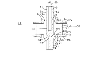
- FIG. 1 is a schematic perspective view of a rotary blade member in the first embodiment.
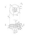
- FIG. 2 is a schematic two-view diagram illustrating a plan view and a front view of the rotary blade member in the first embodiment.
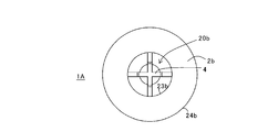
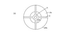
- FIG. 3 is a bottom view of the rotary blade member according to the first embodiment.
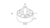
- FIG. 4A is a schematic perspective view of a rotary blade member in a comparative example.
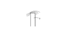
- FIG. 4B is a schematic diagram illustrating how water moves over the large-diameter blades.
- FIG. 7 is a cross-sectional view taken along the line BB in FIG. 8 is a cross-sectional view taken along the line CC of FIG.
- FIG. 9 is a schematic perspective view of a rotary blade member in the second embodiment.
- FIG. 10 is a schematic two-plane view showing a plan view and a front view of the rotary blade member in the second embodiment.
- 11 is a cross-sectional view taken along the line DD in FIG. 12 is a cross-sectional view taken along the line EE of FIG.
- FIG. 13 is a partially cutaway side view of the drainage pump in the third embodiment.
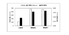
- FIG. 14 is a graph showing the relationship between each rotary blade member and the amount of water discharged from the drainage pump, and the relationship between each rotary blade member and the dead end.
- the rotary blade member for a pump and the drainage pump in the embodiment will be described with reference to the drawings.
- portions and members having the same function are denoted by the same reference numerals, and repeated descriptions of the portions and members having the same reference numerals are omitted.
- the liquid pulled up by the pump rotary blade member is “water”
- the liquid pulled up by the pump rotary blade member is not limited to water and is arbitrary.
- FIG. 1 is a schematic perspective view of a rotary blade member 1A according to the first embodiment.
- FIG. 2 is a schematic two-side view of the rotary blade member 1A in the first embodiment. 2 is a plan view and the lower side of FIG. 2 is a side view.
- FIG. 3 is a bottom view of the rotary blade member 1A in the first embodiment.
- the rotary blade member 1A for a pump in the first embodiment includes a plurality of plate members 2, a large diameter blade 3, and a small diameter blade 4.
- the plurality of plate members 2 include an upper plate 2a and a lower plate 2b, and each outer shape is circular.
- the upper plate 2 a covers at least a part of the upper end of the large-diameter blade 3.
- the large-diameter blade 3 is disposed between the upper plate 2a and the lower plate 2b.
- wing 3) between the upper board 2a and the lower board 2b is a rotary blade for pumps rather than the outer edge 41 of the blade
- the rotary blade member 1A includes the side opening OP (for example, FIG. 1).
- the effect of the example described in (1) will be described.
- FIG. 4A when the large diameter blade 3 rotates around the rotation center axis AX, centrifugal force is applied to the water that collides with the large diameter blade 3.
- the water given centrifugal force collides with the inner surface of the peripheral wall 92, and the momentum of the water decreases.
- the ability of the rotary blade member 90 to pull up the water decreases.
- a side opening OP is formed between the upper plate 2a and the lower plate 2b.
- the water to which the centrifugal force is applied is discharged from the rotary blade member 1A through the side opening OP while maintaining the momentum.
- the rotary blade member 1A in the first embodiment has a higher water pulling ability than the rotary blade member 90 in the comparative example.
- the small diameter blade 4 is disposed below the lower plate 2b.
- the small-diameter blade 4 pulls up water such as drain water that contacts the small-diameter blade 4 when the small-diameter blade 4 rotates about the rotation center axis AX.
- the upper plate 2a includes a circular first hole 20a through which a liquid (eg, drain water) or a gas (ie, fluid) such as air can pass.
- a liquid eg, drain water
- a gas ie, fluid
- the first hole 20 a is formed in the central portion of the upper plate 2 a. Further, the center of the upper plate 2a and the first hole 20a are on the rotation center axis AX.
- the lower plate 2b includes a second hole 20b through which a liquid such as drain water or a gas such as air can pass.
- the second hole 20b is formed in the central portion of the lower plate 2b. Further, the center of the lower plate 2b and the center of the second hole 20b are on the rotation center axis AX.
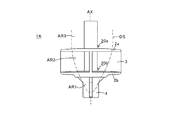
- the gas-liquid boundary surface DS extends from the area AR1 below the lower plate 2b to the area above the upper plate 2a. It is formed across AR3. For this reason, the ability to pull up water by the rotary blade member 1A is high.
- the first hole 20a through which the liquid can pass is not provided in the upper plate 2a, the gas does not enter the lower portion of the upper plate 2a, so that the water pulling ability by the rotary blade member 1A is reduced.
- the rotary blade member 1 ⁇ / b> A in the first embodiment includes the upper plate 2 a that covers at least a part of the upper end of the large-diameter blade 3. For this reason, mixing of water and air is suppressed, and the generation of noise is suppressed.
- 1 A of rotary blade members in 1st Embodiment are provided with side part opening OP between the upper board 2a and the lower board 2b. Then, in a state where the momentum of water is maintained, water is discharged to the outside of the rotary blade member 1A through the side opening OP. For this reason, the ability of the rotary blade member 1A to pull up water is high.
- the upper board 2a is provided with the 1st hole 20a, and the lower board 2b is provided with the 2nd hole 20b.
- the gas-liquid boundary surface DS is formed extensively.
- the ability of the rotary blade member 1A to pull up water is high.
- the upper plate 2a, the lower plate 2b, the large-diameter blade 3 disposed between the upper plate 2a and the lower plate 2b, and the lower plate 2b are disposed below.
- the small-diameter blade 4 By combining the small-diameter blade 4, the first hole 20a provided in the upper plate 2a, and the second hole 20b provided in the lower plate 2b, it is possible to reduce noise generation and improve water lifting ability. Two effects are produced synergistically. Moreover, the water pulling ability is synergistically improved by maintaining the momentum of water and forming the gas-liquid interface DS extensively.
- 6 is a cross-sectional view taken along the line AA in FIG. 2
- FIG. 7 is a cross-sectional view taken along the line BB in FIG. 2
- FIG. 8 is a cross-sectional view taken along the line CC in FIG. .
- the upper plate 2a has a ring shape (annular shape with the same width having a circular hole in the center).
- the upper plate 2a suppresses / prevents drain water sucked up during rotation of the rotary blade member 1A from exceeding above the large-diameter blade 3.
- the lower plate 2 b has a ring shape.
- the lower plate 2b suppresses / prevents the drain water sucked up during rotation of the rotary blade member 1A from passing below the large-diameter blade 3. As a result, bubbles are less likely to be mixed into the discharged drain water, noise during driving of the drain pump can be reduced, and drainage drainage efficiency is improved.
- the upper surface 22a of the upper plate 2a is an inclined surface.
- the water remains on the upper surface 22a of the upper plate 2a when the rotary blade member 1A is stopped.
- the water remaining on the upper surface 22a of the upper plate 2a evaporates and the like, so that a solid component is deposited, and the precipitated solid component may be deposited on the upper surface 22a of the upper plate 2a.
- the upper surface 22a of the upper plate 2a is an inclined surface, water hardly stays on the upper surface 22a of the upper plate 2a when the rotary blade member 1A is stopped. For this reason, it is difficult for solid components to deposit on the upper surface 22a of the upper plate 2a.
- the upper surface 22a of the upper plate 2a is preferably an inclined surface whose position in the vertical direction gradually decreases from the inner edge 23a of the upper plate toward the outer edge 24a of the upper plate.
- the upper surface 22a of the upper plate 2a may be an inclined surface whose position in the vertical direction gradually increases from the inner edge 23a of the upper plate toward the outer edge 24a of the upper plate.
- “the upper surface is an inclined surface” means that at least 50% or more of the area of the upper surface is an inclined surface. Therefore, a part of the upper surface (area less than 50%) may be a horizontal plane.
- the upper surface 22b of the lower plate 2b is an inclined surface.
- the upper surface 22b of the lower plate 2b is an inclined surface, it is difficult for water to stay on the upper surface 22b of the lower plate 2b when the rotary blade member 1A is stopped. For this reason, it is difficult for solid components to deposit on the upper surface 22b of the lower plate 2b.
- the upper surface 22b of the lower plate 2b is preferably an inclined surface whose position in the vertical direction gradually decreases from the inner edge 23b of the lower plate toward the outer edge 24b of the lower plate.
- the upper surface 22b of the lower plate 2b may be an inclined surface whose position in the vertical direction gradually increases from the inner edge 23b of the lower plate toward the outer edge 24b of the lower plate.
- the upper end 30a of the large diameter blade 3 is connected to the lower surface of the upper plate 2a, and the lower end 30b of the large diameter blade 3 is connected to the upper surface of the lower plate 2b. Therefore, the strength of the structure constituted by the upper plate 2a, the large-diameter blade 3 and the lower plate 2b is high. Moreover, since the structural strength of the structure is high, the upper plate 2a, the large-diameter blade 3 and the lower plate 2b can be thinned.
- the outer edge 41 of the small-diameter blade 4 is disposed inside the inner edge 23b of the lower plate 2b in the bottom view. For this reason, most of the water lifted obliquely upward (upward and radially outward) by the small-diameter blades 4 is smoothly guided to the space above the lower plate 2b through the second hole 20b.
- the number of large-diameter blades 3 is four, and the large-diameter blades 3 are arranged at intervals of 90 degrees around the rotation center axis AX.
- the number of the small diameter blades 4 is four, and the small diameter blades 4 are arranged at intervals of 90 degrees around the rotation center axis AX.
- the number of large-diameter blades 3 and the number of small-diameter blades 4 are not limited to four and are arbitrary.
- the inner edges 33 of all the large-diameter blades 3 are directly connected to the rotating shaft 5 described later.
- the inner edge 33 of at least one large-diameter blade 3, the rotating shaft 5, May not be directly connected.
- the number of large diameter blades 3 is N (N is a natural number of 2 or more)
- the number of side openings OP formed between the upper plate 2a and the lower plate 2b is N.
- the side opening OP is an opening defined by the upper plate 2a, the lower plate 2b, and the two large-diameter blades 3.
- the distance L1 between the rotation center axis AX and the outer edge 31 of the large-diameter blade 3 is, for example, 10 mm or more and 20 mm or less. Since the rotary blade member 1A in the first embodiment has a high water pulling ability, it is possible to reduce the diameter of the rotary blade member as compared with the conventional rotary blade member.
- the distance L2 between the upper surface 22a of the upper plate and the lower surface 25b of the lower plate is, for example, not less than 5 mm and not more than 15 mm.
- the outer edge 31 of the large-diameter blade 3 and the outer edge 41 of the small-diameter blade 4 are the lower end 30b of the large-diameter blade 3.
- one large-diameter blade 3 and one small-diameter blade 4 constitute a single plate, and there is a step portion between the large-diameter blade 3 and the small-diameter blade 4.
- the step portion corresponds to the lower end 30 b of the large-diameter blade 3.
- the distance between the inner edge 33 of the large-diameter blade 3 and the rotation center axis AX is smaller than the distance between the inner edge 23a of the upper plate 2a and the rotation center axis AX.
- the inner portion of the large-diameter blade 3 protrudes inward from the upper plate 2a.
- a part of the upper surface of the large-diameter blade 3 (exposed portion 3c) is exposed to the first hole 20a. For this reason, when 1 A of rotary blade members rotate, a part of water may get over the exposed part 3c (mixing of water and air may occur).
- the exposed portion 3c is basically in the region of gas (air). To position. Therefore, water and air are not mixed in the exposed portion 3c when the rotating blade member 1A is rotating in a steady state.
- the upper end of the outer portion of the large-diameter blade 3 is connected to the upper plate 2a. For this reason, water does not move over the upper end of the large-diameter blade 3 in a region outside the gas-liquid interface DS (liquid region).
- the rotary blade member 1 ⁇ / b> A includes a rotary shaft 5.
- the rotating shaft 5 is arrange
- the gap between the outer peripheral surface 5a of the rotating shaft 5 and the inner edge 23a of the upper plate 2a functions as a gap G through which air or the like can pass.
- the rotary shaft 5 and the inner edge 33 of the large-diameter blade 3 are directly connected.
- the large-diameter blade 3 is supported from three directions by the upper plate 2a, the lower plate 2b, and the rotating shaft 5. For this reason, the structural strength of the structure including the large-diameter blade 3, the upper plate 2a, the lower plate 2b, and the rotating shaft 5 is high.
- the rotating shaft 5 includes a shaft hole 50 that receives the output shaft of the motor.
- the engagement between the rotary shaft 5 and the output shaft of the motor is not limited to the press contact between the shaft hole 50 and the output shaft (the output shaft is press-fitted into the shaft hole), and is arbitrary.
- the upper part 51 of the rotating shaft 5 is a part connected to the output shaft of the motor.
- the intermediate portion 52 of the rotating shaft 5 functions as a support portion for the large-diameter blade 3, and the large-diameter blade 3 extends radially from the intermediate portion 52.
- the lower portion 53 of the rotating shaft 5 passes through the second hole 20b of the lower plate 2b.
- wing 4 is extended from the lower part 53 of the rotating shaft 5 radially.
- the lower part 53 of the rotating shaft 5 may be provided with the diameter reducing part 54 from which an outer diameter reduces as it goes below from the upper direction. Due to the presence of the reduced diameter portion 54, the water pulled up by the small diameter blade 4 is smoothly guided toward the large diameter blade 3.
- the small-diameter blade 4 includes an upper part 46, an intermediate part 47, and a lower part 48.
- the distance between the outer edge of the upper part 46 and the rotation center axis AX is larger than the distance between the outer edge of the lower part 48 and the rotation center axis AX.
- the outer edge of the intermediate portion 47 is an inclined surface in which the distance from the rotation center axis AX becomes smaller from the upper side toward the lower side.
- the outer edge of the upper portion 46 and the outer edge of the lower portion 48 are connected via the outer edge of the intermediate portion 47.
- the distance between the outer edge of the small-diameter blade 4 and the rotation center axis AX increases from the lower side to the upper side. For this reason, the water pulled up by the small-diameter blades 4 is smoothly guided toward the large-diameter blades 3.
- the outer edge of the upper portion 46 of the small-diameter blade 4 may be connected to the inner edge 23b of the lower plate 2b.
- the material of each of the upper plate 2a, the large-diameter blade 3, the lower plate 2b, the small-diameter blade 4, and the rotating shaft 5 is resin.
- the upper plate 2a, the large-diameter blade 3, the lower plate 2b, the small-diameter blade 4, and the rotating shaft 5 are integrally formed.
- the upper plate 2a, the large-diameter blade 3, the lower plate 2b, the small-diameter blade 4, and the rotating shaft 5 may be formed by two or more members, and the two or more members may be fixed to each other.
- the diameter of the upper plate 2a and the lower plate 2b and the diameter of the virtual circle connecting the outer edges 31 of the large-diameter blades 3 are all the same, but the embodiment is It is not limited to this, The diameter of the virtual circle which connects the outer edge 31 of the large diameter blade
- the diameter of the imaginary circle connecting the outer edges 31 of the large-diameter blade 3 is smaller than the diameters of the upper plate 2a and the lower plate 2b, the upper portion of the large-diameter blade 3 is the same as in the above-described embodiments.
- the diameter of the upper plate 2a may be different from the diameter of the lower plate 2b.
- FIG. 9 is a schematic perspective view of the rotary blade member 1B according to the second embodiment.
- FIG. 10 is a schematic two-side view of the rotary blade member 1B according to the second embodiment. A plan view is shown on the upper side of FIG. 10, and a side view is shown on the lower side of FIG. 11 is a cross-sectional view taken along the line DD in FIG. 12 is a cross-sectional view taken along the line EE of FIG.
- the pump rotary blade member 1B in the second embodiment is provided with an intermediate plate 2c disposed between the upper plate 2a and the lower plate 2b, and the pump rotary blade member 1A in the first embodiment. Is different. In other respects, the rotary blade member 1B for the pump in the second embodiment is the same as the rotary blade member 1A for the pump in the first embodiment. Therefore, in 2nd Embodiment, it demonstrates centering on the intermediate
- the intermediate plate 2c includes a third hole 20c through which a liquid such as drain water or a gas such as air can pass.
- the third hole 20c is formed in the center of the intermediate plate 2c.
- the center of the intermediate plate 2c and the center of the third hole 20c are on the rotation center axis AX.
- the large-diameter blade 3 has an upper large-diameter blade 3a disposed between the upper plate 2a and the middle plate 2c, and a lower large plate disposed between the middle plate 2c and the lower plate 2b. And a radial blade 3b.
- An upper side opening OP1 is formed between the upper plate 2a and the middle plate 2c, and a lower side opening OP2 is formed between the middle plate 2c and the lower plate 2b. .
- the upper plate 2a When the distance between the upper plate 2a and the lower plate 2b is large and the middle plate 2c is not disposed between the upper plate 2a and the lower plate 2b, the upper plate 2a There is a possibility that the momentum in the vertical direction of water existing between the lower plate 2b and the lower plate 2b increases. Further, due to the large distance between the upper plate 2a and the lower plate 2b, the moving direction of water existing between the upper plate 2a and the lower plate 2b may vary greatly. As a result, water between the upper plate 2a and the lower plate 2b may collide with the upper plate 2a, the lower plate 2b, etc., and noise may be generated.
- the middle plate 2c when the middle plate 2c is disposed between the upper plate 2a and the lower plate 2b, the momentum in the vertical direction of water existing between the upper plate 2a and the lower plate 2b is limited. Moreover, since the distance between the upper plate 2a and the middle plate 2c and the distance between the middle plate 2c and the lower plate 2b are relatively small, variation in the direction of movement of water is reduced. As a result, noise is reduced.
- the second embodiment has the same effects as the first embodiment.
- the rotary blade member 1B in the second embodiment includes an intermediate plate 2c. For this reason, noise is further reduced.
- the intermediate plate 2c has a ring shape.
- the middle plate 2c restricts the upward and downward movement of the drain water sucked up when the rotary blade member 1B is rotated (the movement in the space between the upper plate 2a and the lower plate 2b is substantially restricted at the intermediate portion thereof), Air bubbles are less likely to be mixed with the drain water, and noise during driving of the drain pump is further reduced.
- the upper surface 22c of the intermediate plate 2c is an inclined surface.
- the upper surface 22c of the intermediate plate 2c is preferably an inclined surface whose position in the vertical direction gradually decreases from the inner edge 23c of the intermediate plate toward the outer edge 24c of the intermediate plate.
- the upper surface 22c of the intermediate plate 2c may be an inclined surface whose position in the vertical direction gradually increases from the inner edge 23c of the intermediate plate toward the outer edge 24c of the intermediate plate.
- the upper end 30a of the upper large-diameter blade 3a is connected to the lower surface of the upper plate 2a, and the lower end of the upper large-diameter blade 3a is connected to the upper surface of the middle plate 2c.
- the upper end of the lower large-diameter blade 3b is connected to the lower surface of the middle plate 2c, and the lower end 30b of the lower large-diameter blade 3b is connected to the upper surface of the lower plate 2b.
- the strength of the structure constituted by the upper plate 2a, the upper large-diameter blade 3a, the middle plate 2c, the lower large-diameter blade 3b, and the lower plate 2b is high.
- the structural strength of the structure is high, the upper plate 2a, the upper large-diameter blade 3a, the middle plate 2c, the lower large-diameter blade 3b, and the lower plate 2b can be thinned.
- one upper large-diameter blade 3 a, one lower large-diameter blade 3 b, and one small-diameter blade 4 constitute a single plate. That is, the inner portion of the upper large-diameter blade 3a and the inner portion of the lower large-diameter blade 3b are connected via the connecting portion 38, and the lower end of the lower large-diameter blade 3b and the upper end of the small-diameter blade 4 are also connected. ing.
- the material of the upper plate 2a, the upper large-diameter blade 3a, the middle plate 2c, the lower large-diameter blade 3b, the lower plate 2b, the small-diameter blade 4, and the rotary shaft 5 is resin.
- the upper plate 2a, the upper large-diameter blade 3a, the middle plate 2c, the lower large-diameter blade 3b, the lower plate 2b, the small-diameter blade 4 and the rotating shaft 5 are integrally formed.
- the upper plate 2a, the upper large-diameter blade 3a, the middle plate 2c, the lower large-diameter blade 3b, the lower plate 2b, the small-diameter blade 4 and the rotating shaft 5 are formed by two or more members, and two or more These members may be fixed to each other.
- the number of the upper large-diameter blades 3a is four, and the upper large-diameter blades 3a are arranged at intervals of 90 degrees around the rotation center axis AX.
- the number of the lower large-diameter blades 3b is four, and the lower large-diameter blades 3b are arranged at intervals of 90 degrees around the rotation center axis AX.
- the number of the upper large-diameter blades 3a and the number of the lower large-diameter blades 3b are not limited to four and are arbitrary. In the example shown in FIG.
- the inner edges 33 of all the upper large-diameter blades 3a are directly connected to the rotating shaft 5, but the inner edge 33 of at least one upper large-diameter blade 3a, the rotating shaft 5, May not be directly connected.
- the inner edges 33 of all the lower large-diameter blades 3b may be directly connected to the rotating shaft 5, or the inner edge 33 of at least one lower large-diameter blade 3b and the rotating shaft 5 are directly connected. It does not have to be.
- the upper large-diameter blades 3a and the number of the lower large-diameter blades 3b are N (N is a natural number of 2 or more)
- the upper large-diameter blades 3a are formed between the upper plate 2a and the lower plate 2b.
- the number of side openings OP is 2N.
- the upper side opening OP1 is an opening defined by the upper plate 2a, the middle plate 2c, and the two upper large-diameter blades 3a
- the lower side opening OP2 is the middle plate 2c.
- the opening is defined by the lower plate 2b and the two lower large-diameter blades 3b.
- the number of the intermediate plates 2c is one has been described.
- the number of middle plates 2c disposed between the upper plate 2a and the lower plate 2b may be two or more.
- the embodiment is not limited to this, and as in the first embodiment, the diameter of the virtual circle connecting the outer edges 31 of the large-diameter blades 3, the upper plate 2a, and the middle plate The dimensions may be different from the diameters of 2c and lower plate 2b.
- the diameters of the upper plate 2a, the middle plate 2c, and the lower plate 2b may be such that at least one of them is different from the other diameters.
- the middle plate 2c since the middle plate 2c only restricts the movement of fluid between the upper plate 2a and the lower plate 2b, if the diameter of the middle plate 2c is made smaller than the diameter of the upper plate 2a and the lower plate 2b, It is possible to obtain both the effect of suppressing the weight increase (or weight reduction) and the quietness due to the provision of the plate 2c.
- FIG. 13 is a partially cutaway side view of the drainage pump 100 according to the third embodiment.
- the pump case 110 and a part of the motor support member 130 are notched so that the inside can be visually recognized.
- the drainage pump 100 in the third embodiment includes a rotary blade member 1A in the first embodiment or a rotary blade member 1B in the second embodiment, a pump case 110 having a pump chamber that houses the rotary blade member, and a motor. 120, a motor support member 130 for supporting the motor 120, and a motor output shaft 140 connected to the rotary blade member.
- a rotary blade member is the rotary blade member 1B in the second embodiment
- the rotary blade member may be the rotary blade member 1A in the first embodiment.
- the pump case 110 includes a lower housing 111 that defines the pump chamber SP, a lid member 113 that is connected to the lower housing 111 and covers the upper portion of the lower housing 111, a suction pipe 115 that defines the suction port 115a, and a discharge port 116a. And a discharge pipe 116 to be defined.
- the lower housing 111 integrally includes a suction pipe 115 and a discharge pipe 116, but the lower housing 111, the suction pipe 115, and the discharge pipe 116 are prepared as separate bodies, These may be joined together. A part of the small-diameter blade 4 of the rotary blade member 1B is inserted into the suction pipe 115.
- the discharge pipe 116 extends horizontally from the side wall of the pump case 110 toward the outside.
- the height of the discharge port 116a (that is, the boundary between the pump chamber SP and the internal flow path of the discharge pipe 116) is lower than the height of the upper plate 2a and higher than the height of the lower plate 2b. More specifically, the upper end of the discharge port 116a is lower than the height of the upper plate 2a, and the lower end of the discharge port 116a is higher than the height of the lower plate 2b.
- the pump chamber SP has an upper large-diameter space and an inverted frustoconical space that is disposed below the large-diameter space and decreases in diameter toward the lower side.
- the upper part of the large-diameter space is connected to the through hole 113a of the lid member 113, and the inverted frustoconical space is connected to the internal flow path of the suction pipe 115.
- the lid member 113 has a through hole 113a in the center. And the above-mentioned rotation shaft 5 or the motor output shaft 140 connected with the above-mentioned rotation shaft 5 is inserted in the through-hole 113a.
- a seal member 113 b such as an O-ring is disposed between the lid member 113 and the lower housing 111.
- the shape and structure of the pump case 110 and the shape of the pump chamber SP are not limited to the example shown in FIG. 13 and are arbitrary.
- a motor support member 130 that supports the motor 120 is disposed above the pump case 110.
- the motor support member 130 includes a mounting bracket 131 at the top.
- the motor support member 130 includes an upper member 133 and a lower member 135, and the upper member 133 and the lower member 135 are configured to be detachable via an engagement member 137. ing.
- the motor 120 transmits power to the motor output shaft 140.
- the rotary blade member 1B connected to the motor output shaft 140 rotates.
- the small-diameter blade 4 pulls up the water in the suction pipe 115 toward the upper space by centrifugal force. Centrifugal force is applied to the water pulled up in the space between the lower plate 2 b and the upper plate 2 a by the large-diameter blade 3. As a result, water is discharged toward the flow path in the discharge pipe 116.
- the drainage pump 100 is excellent in silence. Further, a hole is provided in the center of the upper plate 2a and the center of the lower plate 2b (in the example shown in FIG. 13, the center of the upper plate 2a, the center of the middle plate 2c, and the lower plate 2b There is a hole in the center). For this reason, in the example shown in FIG. 13, the gas-liquid interface is formed extensively during the operation of the drainage pump 100. As a result, the water pumping capacity of the drainage pump 100 is high. Further, the rotary blade member 1B includes a side opening OP. Therefore, the water to which the centrifugal force is applied is discharged as it is toward the discharge pipe 116. For this reason, the water pulling capacity of the drainage pump 100 is high.
- FIG. 14 is a graph showing the relationship between each rotary blade member and the amount of water discharged from the drainage pump 100, and the relationship between each rotary blade member and the dead end.
- the discharge amount is that when the lifting height is 1200 mm
- the deadline lifting height means the suction height.
- the comparative example shows the result of applying the rotary blade member 90 shown in FIG. 4A to the drainage pump 100
- Example 2 shows the result of applying the rotary blade member 1B in the second embodiment to the drainage pump 100
- Example 1 shows the result of applying the rotary blade member 1 ⁇ / b> A in the first embodiment to the drainage pump 100.
- Example 1 and Example 2 it was found that the amount of water discharged from the drainage pump 100 was dramatically increased as compared with the comparative example (about 4 times). It was found that the amount of water discharged can be realized). Moreover, in Example 1 and Example 2, it turned out that the deadline lift is also increasing compared with the comparative example.
- the present invention is not limited to the above-described embodiment.
- the above-described embodiments can be freely combined, or any component of each embodiment can be modified, or any component can be omitted in each embodiment.
- Rotating blade member 1B Rotating blade member 2a: Upper plate 2b: Lower plate 2c: Middle plate 3: Large blade 3a: Upper large blade 3b: Lower large blade 3c: Exposed portion 4: Small blade 5 : Rotating shaft 5a: outer peripheral surface 20a: first hole 20b: second hole 20c: third holes 22a, 22b, 22c: upper surface 23a, 23b, 23c: inner edge 24a, 24b, 24c: outer edge 25b: lower surface 30a: upper end 30b : Lower end 31: Outer edge 33: Inner edge 38: Connection part 41: Outer edge 46: Upper part 47: Intermediate part 48: Lower part 50: Shaft hole 51: Upper part 52: Intermediate part 53: Lower part 54: Reduced diameter part 90: Rotary blade member 92 : Peripheral wall 100: drainage pump 110: pump case 111: lower housing 11 3: lid member 113a: through hole 113b: seal member 115: suction pipe 115a: suction port 116: discharge pipe 116a: discharge port
Landscapes
- Engineering & Computer Science (AREA)
- Mechanical Engineering (AREA)
- General Engineering & Computer Science (AREA)
- Structures Of Non-Positive Displacement Pumps (AREA)
Abstract
本発明は、水等の液体の引き上げ能力の高いポンプ用回転羽根部材および排水ポンプを提供することを目的としている。 上記の目的を達成するため、本発明のポンプ用回転羽根部材は、上板と下板とを含む複数の板部材と、上板と下板との間に配置された大径羽根と、下板の下方に配置された小径羽根とを具備する。上板と下板との間には側部開口が形成されている。上板は、流体が通過可能な第1孔を備え、下板は、流体が通過可能な第2孔を備える。
Description
本発明は、ポンプ用回転羽根部材および排水ポンプに関する。
排水ポンプは液体を引き込み(吸込み)、引き込まれた液体をポンプ外に排出するために使用される。この排水ポンプには、回転して液体を吸い込むためのポンプ用回転羽根部材が用いられる。
関連する技術として、特許文献1には、空調装置で凝縮されたドレン水などを排水するための排水ポンプが開示されている。特許文献1に記載の排水ポンプは、本特許出願人により出願されたものであり、ドレン水を吸い上げ、排出させる為の回転羽根を備える。回転羽根は、大径羽根と、小径羽根と、大径羽根と小径羽根との間に設けられ中央に開口部(孔)を備えた円盤状の部材と、大径羽根の外周縁を連結する壁部材とを備える。特許文献1に記載の排水ポンプでは、排水ポンプの停止時に、吐出口側から吸入口側に流れる戻り水は、大径羽根の外周縁を連結する壁部材に突き当たって緩衝され、スムーズに落下する。したがって、戻り水がポンプハウジングの上部から噴出することがなくなり、また当該排水ポンプの駆動時における騒音も低減する。
特許文献1に記載の排水ポンプでは、大径羽根の外周縁を連結する壁部材を備える。このため、回転羽根によって引き上げられた水は、すべて、回転羽根の上部から放出され、回転羽根の側部から水が放出されることはない。特許文献1に記載の排水ポンプでは、回転羽根の側部から水が放出されないため、水に付与される遠心力が相対的に小さい。その結果、排水ポンプの水の引き上げ能力が高いとはいえない。
そこで、本発明の目的は、水等の液体の引き上げ能力の高いポンプ用回転羽根部材および排水ポンプを提供することにある。あるいは、本発明の目的は、ポンプ用回転羽根部材の小径化を可能とするポンプ用回転羽根部材および排水ポンプを提供することにある。
上記目的を達成するために、本発明によるポンプ用回転羽根部材は、上板と下板とを含む複数の板部材と、前記上板と前記下板との間に配置された大径羽根と、前記下板の下方に配置された小径羽根とを具備する。前記上板と前記下板との間には側部開口が形成されている。前記上板は、流体が通過可能な第1孔を備える。また、前記下板は、流体が通過可能な第2孔を備える。
前記大径羽根の外端を結ぶ仮想円の直径を、前記上板及び/又は前記下板の直径と同一又は異なるようにしても良い。
また、上記ポンプ用回転羽根部材において、前記複数の板部材は、前記上板と前記下板との間に配置された中板を更に具備していてもよい。前記中板は、流体が通過可能な第3孔を備える。
また、前記中板の直径は、前記上板及び/又は前記下板の直径と同一又は異なるようにしても良い。
また、上記ポンプ用回転羽根部材において、前記複数の板部材は、前記上板と前記下板との間に配置された中板を更に具備していてもよい。前記中板は、流体が通過可能な第3孔を備える。
また、前記中板の直径は、前記上板及び/又は前記下板の直径と同一又は異なるようにしても良い。
上記ポンプ用回転羽根部材において、前記複数の板部材の各々は、リング形状を有していてもよい。
上記ポンプ用回転羽根部材において、前記複数の板部材の各々の上面は、傾斜面であってもよい。
上記ポンプ用回転羽根部材において、前記小径羽根の外縁は、底面視で、前記下板の内縁の内側に配置されていてもよい。
上記ポンプ用回転羽根部材において、前記第1孔を通過するように配置された回転シャフトを更に具備していてもよい。また、前記上板と前記下板との間に配置された前記大径羽根は、前記回転シャフトに直接接続されていてもよい。
本発明による排水ポンプは、上述のいずれかの段落に記載のポンプ用回転羽根部材と、前記ポンプ用回転羽根部材を収容するポンプ室を有するポンプケースと、ポンプ用回転羽根部材を回転駆動するモータと、前記モータを支持するモータ支持部材とを具備する。
本発明により、水等の液体の引き上げ能力の高いポンプ用回転羽根部材および排水ポンプを提供することができる。あるいは、本発明により、ポンプ用回転羽根部材を小径化することができる。
以下、図面を参照して、実施形態におけるポンプ用回転羽根部材および排水ポンプについて説明する。なお、以下の実施形態の説明において、同一の機能を有する部位、部材については同一の符号を付し、同一の符号が付された部位、部材についての繰り返しとなる説明は省略する。なお、以下の実施形態において、ポンプ用回転羽根部材が引き上げる液体が「水」である例について説明する。しかし、ポンプ用回転羽根部材が引き上げる液体は、水に限定されず任意である。
(第1の実施形態)
図1乃至図3を参照して、第1の実施形態におけるポンプ用の回転羽根部材1Aについて説明する。図1は、第1の実施形態における回転羽根部材1Aの概略斜視図である。図2は、第1の実施形態における回転羽根部材1Aの概略2面図である。図2の上側には、平面図が記載され、図2の下側には、側面図が記載されている。図3は、第1の実施形態における回転羽根部材1Aの底面図である。
図1乃至図3を参照して、第1の実施形態におけるポンプ用の回転羽根部材1Aについて説明する。図1は、第1の実施形態における回転羽根部材1Aの概略斜視図である。図2は、第1の実施形態における回転羽根部材1Aの概略2面図である。図2の上側には、平面図が記載され、図2の下側には、側面図が記載されている。図3は、第1の実施形態における回転羽根部材1Aの底面図である。
第1の実施形態におけるポンプ用の回転羽根部材1Aは、複数の板部材2と、大径羽根3と、小径羽根4とを具備する。
図1に記載の例では、複数の板部材2は、上板2aと下板2bとを含み、それぞれの外形形状は円形である。上板2aは、大径羽根3の上端の少なくとも一部を覆う。
図4Aに記載された比較例(ポンプ用の回転羽根部材90が、上板を備えない場合の例)を参照しつつ、ポンプ用の回転羽根部材1Aが上板2aを備える場合(例えば、図1に記載の例)の効果について説明する。図4Aおよび図4Bに示されるように、水が大径羽根3を乗り越えて移動する場合を想定する。水が大径羽根3を乗り越えて移動すると、水が空気と混合され、水に多くの気泡が巻き込まれる。多くの気泡を含む水が排水ポンプの壁面等に衝突すると、騒音が発生する。これに対し、第1の実施形態におけるポンプ用の回転羽根部材1Aは、上板2aを含む。このため、水が大径羽根3を乗り越えて移動することがない。あるいは、大径羽根3(より具体的には、後述の露出部3c)を乗り越えて移動する水が少ない。こうして、水と空気との混合が抑制され、水に含まれる気泡の量が低減される。その結果、水が排水ポンプの壁面等に衝突することに起因して発生する騒音が低減される。
図1を参照して、大径羽根3は、上板2aと下板2bとの間に配置される。また、上板2aと下板2bとの間にある羽根(大径羽根3)の外縁31は、下板2bの下方にある羽根(小径羽根4)の外縁41よりも、ポンプ用の回転羽根部材の回転中心軸AXから遠い位置にある。このため、本明細書では、上板2aと下板2bとの間にある羽根のことを「大径羽根」と呼び、下板2bの下方にある羽根のことを「小径羽根」と呼ぶ。
図4Aに記載された比較例(大径羽根3の外縁部の全体が周壁92によって囲まれている例)を参照しつつ、回転羽根部材1Aが側部開口OPを備える場合(例えば、図1に記載の例)の効果について説明する。図4Aに記載の例において、大径羽根3が回転中心軸AXまわりを回転すると、大径羽根3に衝突する水には遠心力が付与される。遠心力を付与された水は、周壁92の内面に衝突し、水の運動量が低下する。水の運動量が低下する結果、回転羽根部材90の水の引き上げ能力が低下する。これに対し、第1の実施形態における回転羽根部材1Aでは、上板2aと下板2bとの間に、側部開口OPが形成されている。このため、遠心力を付与された水は、運動量を維持した状態で、回転羽根部材1Aから、側部開口OPを介して、放出される。このため、第1の実施形態における回転羽根部材1Aは、比較例における回転羽根部材90と比較して、水の引き上げ能力が高い。
小径羽根4は、下板2bの下方に配置される。小径羽根4は、小径羽根4が回転中心軸AXまわりを回転することにより、小径羽根4に接触するドレン水等の水を上方に引き上げる。
図2に示されるように、上板2aは、ドレン水などの液体や空気などの気体(すなわち流体)が通過可能な円形の第1孔20aを備える。図1に記載の例では、第1孔20aは、上板2aの中央部に形成されている。また、上板2aの中心、および、第1孔20aは、回転中心軸AX上にある。
図3に示されるように、下板2bは、ドレン水などの液体や空気などの気体が通過可能な第2孔20bを備える。図3に記載の例では、第2孔20bは、下板2bの中央部に形成されている。また、下板2bの中心、および、第2孔20bの中心は、回転中心軸AX上にある。
上板2aが第1孔20aを備え、下板2bが第2孔20bを備えることによる効果について説明する。図5を参照して、回転羽根部材1Aが回転中心軸AXまわりを回転するとき、回転羽根部材1Aに衝突する水には遠心力が付与される。その結果、排水ポンプのポンプ室内には、気液境界面DSが形成される。気液境界面DSの外側には液体(水)が存在し、気液境界面DSの内側には気体(空気)が存在する。
上板2aが第1孔20aを備え、下板2bが第2孔20bを備える場合には、当該気液境界面DSが、下板2bの下方の領域AR1から、上板2aの上方の領域AR3に跨って形成される。このため、回転羽根部材1Aによる水の引き上げ能力が高い。これに対し、上板2aに液体が通過可能な第1孔20aが設けられない場合には、上板2aの下方に気体が入らないため、回転羽根部材1Aによる水の引き上げ能力が低下する。また、下板2bに液体が通過可能な第2孔20bが設けられない場合には、下板2bの下方に気体が入らないため、小径羽根4による水の引き上げ(吸い上げ)能力が低下する。
以上のとおり、第1の実施形態における回転羽根部材1Aは、大径羽根3の上端の少なくとも一部を覆う上板2aを備える。このため、水と空気との混合が抑制され、騒音の発生が抑制される。また、第1の実施形態における回転羽根部材1Aは、上板2aと下板2bとの間に側部開口OPを備える。そして、水の運動量が維持された状態で、水が、側部開口OPを通って、回転羽根部材1Aの外部に放出される。このため、回転羽根部材1Aの水の引き上げ能力が高い。さらに、第1の実施形態では、上板2aが第1孔20aを備え、下板2bが第2孔20bを備える。このため、広範に気液境界面DSが形成される。その結果、回転羽根部材1Aの水の引き上げ能力が高い。
第1の実施形態における回転羽根部材1Aでは、上板2aと、下板2bと、上板2aと下板2bとの間に配置された大径羽根3と、下板2bの下方に配置された小径羽根4と、上板2aに設けられた第1孔20aと、下板2bに設けられた第2孔20bとが組み合わせられることにより、騒音発生の低減と、水の引き上げ能力の向上という2つの効果が相乗的に奏される。また、水の引き上げ能力は、水の運動量が維持されることと、気液境界面DSが広範に形成されることとによって、相乗的に向上する。
(第1の実施形態のより詳細な説明)
図1乃至図3、および、図6乃至図8を参照して、第1の実施形態の一例についてより詳細に説明する。図6は、図2のA-A矢視断面図であり、図7は、図2のB-B矢視断面図であり、図8は、図2のC-C矢視断面図である。
図1乃至図3、および、図6乃至図8を参照して、第1の実施形態の一例についてより詳細に説明する。図6は、図2のA-A矢視断面図であり、図7は、図2のB-B矢視断面図であり、図8は、図2のC-C矢視断面図である。
図2に記載の例では、上板2aは、リング形状(中央に円形孔を有する同一幅の環状形状)を有する。上板2aは、当該回転羽根部材1Aの回転時に吸い上げられたドレン水が大径羽根3の上方を越えるのを抑制・防止する。この結果、吐き出されるドレン水に気泡が混じりにくくなり、当該排水ポンプの駆動時の騒音を低減することができる。また、図3に記載の例では、下板2bは、リング形状を有する。下板2bは、当該回転羽根部材1Aの回転時に吸い上げられたドレン水が大径羽根3の下方を通過するのを抑制・防止する。この結果、吐き出されるドレン水に気泡が混じりにくくなり、当該排水ポンプの駆動時の騒音を低減することができると共に、ドレン水の排水効率が向上する。
図2に記載の例では、上板2aの上面22aは、傾斜面である。上板2aの上面22aが、水平面である場合には、回転羽根部材1Aの停止時に、水が上板2aの上面22aに留まる。この場合、上板2aの上面22aに留まる水が蒸発等することにより固形成分が析出し、析出した固形成分が上板2aの上面22aに堆積する可能性がある。これに対し、上板2aの上面22aが傾斜面である場合には、回転羽根部材1Aの停止時に、水が上板2aの上面22aに留まりにくい。このため、上板2aの上面22aに固形成分が堆積しにくい。
なお、上板2aの上面22aは、上板の内縁23aから上板の外縁24aに向けて、鉛直方向の位置が徐々に下がる傾斜面であることが好ましい。しかし、上板2aの上面22aは、上板の内縁23aから上板の外縁24aに向けて、鉛直方向の位置が徐々に上がる傾斜面であっても構わない。なお、本明細書において、「上面が傾斜面である」とは、上面の面積のうちの少なくとも50%以上が傾斜面であることを意味する。よって、上面の一部(50%未満の面積)が、水平面であっても構わない。
同様に、図1に記載の例では、下板2bの上面22bは、傾斜面である。下板2bの上面22bが傾斜面である場合には、回転羽根部材1Aの停止時に、水が下板2bの上面22bに留まりにくい。このため、下板2bの上面22bに固形成分が堆積しにくい。
なお、下板2bの上面22bは、下板の内縁23bから下板の外縁24bに向けて、鉛直方向の位置が徐々に下がる傾斜面であることが好ましい。しかし、下板2bの上面22bは、下板の内縁23bから下板の外縁24bに向けて、鉛直方向の位置が徐々に上がる傾斜面であっても構わない。
図2に記載の例では、大径羽根3の上端30aが上板2aの下面に連結され、大径羽根3の下端30bが下板2bの上面に連結されている。よって、上板2aと、大径羽根3と、下板2bとによって構成される構造体の強度が高い。また、構造体の構造強度が高いため、上板2a、大径羽根3、下板2bの薄肉化が可能である。
図2および図3に記載の例では、小径羽根4の外縁41は、底面視で、下板2bの内縁23bの内側に配置されている。このため、小径羽根4によって斜め上方(上方かつ径外方向)に向けて持ち上げられる水の大部分が、第2孔20bを介して、下板2bの上方の空間にスムーズに案内される。
図2および図3に記載の例では、大径羽根3の数は4個であり、大径羽根3は、回転中心軸AXまわりに、90度間隔で配置されている。また、小径羽根4の数は4個であり、小径羽根4は、回転中心軸AXまわりに、90度間隔で配置されている。しかし、大径羽根3の数、および、小径羽根4の数の各々は、4個に限定されず、任意である。また、図2に記載の例では、すべての大径羽根3の内縁33が、後述の回転シャフト5に直接接続されているが、少なくとも1つの大径羽根3の内縁33と、回転シャフト5とは、直接接続されていなくてもよい。なお、大径羽根3の数が、N個(Nは、2以上の自然数)である時、上板2aと下板2bとの間に形成される側部開口OPの数は、N個となる。なお、側部開口OPは、上板2aと、下板2bと、2個の大径羽根3とによって規定される開口である。
図6(図2のA-A矢視断面図)を参照して、回転中心軸AXと大径羽根3の外縁31との間の距離L1は、例えば、10mm以上20mm以下である。第1の実施形態における回転羽根部材1Aは、水の引き上げ能力が高いため、従来の回転羽根部材と比較して、回転羽根部材を小径化することが可能である。なお、上板の上面22aと下板の下面25bとの間の距離L2は、例えば、5mm以上15mm以下である。
図6、および、図7(図2のB-B矢視断面図)に記載の例では、大径羽根3の外縁31と、小径羽根4の外縁41とは、大径羽根3の下端30bを介して繋がっている。換言すれば、1個の大径羽根3と1個の小径羽根4とによって一枚の板が構成され、当該大径羽根3と小径羽根4との間には段差部がある。当該段差部は、大径羽根3の下端30bに対応する。
図7に記載の例では、大径羽根3の内縁33と回転中心軸AXとの間の距離は、上板2aの内縁23aと回転中心軸AXとの間の距離よりも小さい。換言すれば、大径羽根3の内側部分が、上板2aよりも内方に突出している。この場合、大径羽根3の上面の一部(露出部3c)は、第1孔20aに露出することとなる。このため、回転羽根部材1Aが回転するとき、水の一部が露出部3cを乗り越える可能性がある(水と空気との混合が起こる可能性がある)。しかし、回転羽根部材1Aが定常回転している時に、気液境界面DSは、露出部3cよりも外側に位置するため、露出部3cは、基本的には、気体(空気)の領域内に位置する。よって、回転羽根部材1Aが定常回転している時に、露出部3cにおいて、水と空気とが混合されることはない。
図7に記載の例では、大径羽根3の外側部分の上端が、上板2aに接続されている。このため、気液境界面DSよりもの外側の領域(液体の領域)において、水が、大径羽根3の上端を乗り越えるように移動することはない。
図7に記載の例では、回転羽根部材1Aは、回転シャフト5を備える。そして、回転シャフト5は、上板2aの第1孔20aを通過するように配置されている。このため、回転シャフト5の外周面5aと、上板2aの内縁23aとの間の隙間が、空気などが通過可能な隙間Gとして機能する。
また、図7に記載の例では、回転シャフト5と大径羽根3の内縁33とは、直接接続されている。そして、大径羽根3は、上板2aと下板2bと回転シャフト5とによって、3方から支持されている。このため、大径羽根3と、上板2aと、下板2bと、回転シャフト5とを含む構造体の構造強度が高い。
図7に記載の例では、回転シャフト5は、モータの出力軸を受け入れる軸穴50を備える。なお、回転シャフト5とモータの出力軸との間の係合は、軸穴50と、出力軸との間の圧接(出力軸が軸穴に圧入されること)に限定されず任意である。
図7に記載の例では、回転シャフト5の上部51は、モータの出力軸に連結される部分である。また、回転シャフト5の中間部52は、大径羽根3の支持部として機能し、中間部52から、大径羽根3が放射状に延びている。回転シャフト5の下部53は、下板2bの第2孔20bを通過している。そして、回転シャフト5の下部53からは、小径羽根4が、放射状に延びている。なお、回転シャフト5の下部53は、上方から下方に向かうにつれて外径が減少する縮径部54を備えていてもよい。縮径部54の存在により、小径羽根4によって引き上げられた水が、大径羽根3に向けてスムーズに案内される。
図7に記載の例では、小径羽根4は、上部46と、中間部47と、下部48とを備える。上部46の外縁と回転中心軸AXとの間の距離は、下部48の外縁と回転中心軸AXとの間の距離よりも大きい。また、中間部47の外縁は、上方から下方に向かうにつれて、回転中心軸AXとの間の距離が小さくなる傾斜面である。そして、上部46の外縁と下部48の外縁とは、中間部47の外縁を介して繋がっている。
図7に記載の例では、小径羽根4の外縁と回転中心軸AXとの間の距離は、下方から上方に向かうにつれ、大きくなる。このため、小径羽根4によって引き上げられた水が、大径羽根3に向けてスムーズに案内される。図7に記載の例では、小径羽根4の上部46の外縁と、下板2bの内縁23bとの間には隙間がある。代替的に、小径羽根4の上部46の外縁は、下板2bの内縁23bに接続されていてもよい。
図7に記載の例では、上板2a、大径羽根3、下板2b、小径羽根4、回転シャフト5の各々の材質は、樹脂である。また、上板2a、大径羽根3、下板2b、小径羽根4、および、回転シャフト5は、一体成形されている。代替的に、上板2a、大径羽根3、下板2b、小径羽根4、および、回転シャフト5が2個以上の部材によって形成され、2個以上の部材が互いに固着されてもよい。
なお、各図に示された第1の実施形態においては、上板2a及び下板2bの直径、並びに大径羽根3の外縁31を結ぶ仮想円の直径は全て同一であるが、実施形態はこれに限定されることはなく、大径羽根3の外縁31を結ぶ仮想円の直径と、上板2a及び下板2bの直径とは異なる寸法であっても良い。大径羽根3の外縁31を結ぶ仮想円の直径が、上板2a及び下板2bの直径よりも小さい場合には、上述の各図に示された実施形態と同様、大径羽根3の上方及び下方にドレン水が移動することが良好に抑制・防止され、この結果、吐き出されるドレン水に気泡が混じりにくくなり、当該排水ポンプの駆動時の騒音を低減することができると共に、ドレン水の排水効率が向上する。
また、上板2aの直径と下板2bの直径とを、異なるようにしても良いことは当然である。
なお、各図に示された第1の実施形態においては、上板2a及び下板2bの直径、並びに大径羽根3の外縁31を結ぶ仮想円の直径は全て同一であるが、実施形態はこれに限定されることはなく、大径羽根3の外縁31を結ぶ仮想円の直径と、上板2a及び下板2bの直径とは異なる寸法であっても良い。大径羽根3の外縁31を結ぶ仮想円の直径が、上板2a及び下板2bの直径よりも小さい場合には、上述の各図に示された実施形態と同様、大径羽根3の上方及び下方にドレン水が移動することが良好に抑制・防止され、この結果、吐き出されるドレン水に気泡が混じりにくくなり、当該排水ポンプの駆動時の騒音を低減することができると共に、ドレン水の排水効率が向上する。
また、上板2aの直径と下板2bの直径とを、異なるようにしても良いことは当然である。
(第2の実施形態)
図9乃至図12を参照して、第2の実施形態におけるポンプ用の回転羽根部材1Bについて説明する。図9は、第2の実施形態における回転羽根部材1Bの概略斜視図である。図10は、第2の実施形態における回転羽根部材1Bの概略2面図である。図10の上側には、平面図が記載され、図10の下側には、側面図が記載されている。図11は、図10のD-D矢視断面図である。図12は、図10のE-E矢視断面図である。
図9乃至図12を参照して、第2の実施形態におけるポンプ用の回転羽根部材1Bについて説明する。図9は、第2の実施形態における回転羽根部材1Bの概略斜視図である。図10は、第2の実施形態における回転羽根部材1Bの概略2面図である。図10の上側には、平面図が記載され、図10の下側には、側面図が記載されている。図11は、図10のD-D矢視断面図である。図12は、図10のE-E矢視断面図である。
第2の実施形態におけるポンプ用の回転羽根部材1Bは、上板2aと下板2bとの間に配置された中板2cを備える点において、第1の実施形態におけるポンプ用の回転羽根部材1Aとは異なる。その他の点では、第2の実施形態におけるポンプ用の回転羽根部材1Bは、第1の実施形態におけるポンプ用の回転羽根部材1Aと同様である。よって、第2の実施形態では、中板2cを中心に説明し、その他の構成についての繰り返しとなる説明は省略する。
図12に示されるように、中板2cは、ドレン水などの液体や空気などの気体が通過可能な第3孔20cを備える。図12に記載の例では、第3孔20cは、中板2cの中央部に形成されている。また、中板2cの中心、および、第3孔20cの中心は、回転中心軸AX上にある。
図9を参照して、大径羽根3は、上板2aと中板2cとの間に配置された上部大径羽根3aと、中板2cと下板2bとの間に配置された下部大径羽根3bとを備える。そして、上板2aと中板2cとの間には、上側の側部開口OP1が形成され、中板2cと下板2bとの間には、下側の側部開口OP2が形成されている。
上板2aと下板2bとの間の距離が大きく、かつ、上板2aと下板2bとの間に中板2cが配置されない場合には、回転羽根部材の回転に伴い、上板2aと下板2bとの間に存在する水の上下方向の運動量が大きくなる可能性がある。また、上板2aと下板2bとの間の距離が大きいことに起因して、上板2aと下板2bとの間に存在する水の移動方向が、大きくばらつく可能性がある。その結果、上板2aと下板2bとの間の水が、上板2aまたは下板2b等に衝突し、騒音が発生する可能性がある。これに対し、上板2aと下板2bとの間に、中板2cが配置される場合には、上板2aと下板2bとの間に存在する水の上下方向の運動量が制限される。また、上板2aと中板2cとの間の距離、および、中板2cと下板2bとの間の距離が、相対的に小さいため、水の移動方向のばらつきが低減される。その結果、騒音が低減される。
第2の実施形態は、第1の実施形態と同様の効果を奏する。加えて、第2の実施形態における回転羽根部材1Bは、中板2cを備える。このため、騒音がより一層低減される。
(第2の実施形態のより詳細な説明)
図9乃至図12を参照して、第2の実施形態の一例についてより詳細に説明する。
図9乃至図12を参照して、第2の実施形態の一例についてより詳細に説明する。
図12に記載の例では、中板2cは、リング形状を有する。中板2cは、当該回転羽根部材1Bの回転時に吸い上げられたドレン水の上下の移動を制限(上板2aと下板2bとの間の空間内の移動をほぼその中間部において制限)し、該ドレン水に気泡を混じりにくくし、当該排水ポンプの駆動時の騒音をさらに低減する。
図11(図10のD-D矢視断面図)に記載の例では、中板2cの上面22cは、傾斜面である。中板2cの上面22cが傾斜面である場合には、回転羽根部材1Bの停止時に、水が中板2cの上面22cに留まりにくい。このため、中板2cの上面22cに固形成分が堆積しにくい。なお、中板2cの上面22cは、中板の内縁23cから中板の外縁24cに向けて、鉛直方向の位置が徐々に下がる傾斜面であることが好ましい。しかし、中板2cの上面22cは、中板の内縁23cから中板の外縁24cに向けて、鉛直方向の位置が徐々に上がる傾斜面であっても構わない。
図11に記載の例では、上部大径羽根3aの上端30aが上板2aの下面に連結され、上部大径羽根3aの下端が中板2cの上面に連結されている。また、下部大径羽根3bの上端が中板2cの下面に連結され、下部大径羽根3bの下端30bが下板2bの上面に連結されている。このため、上板2aと、上部大径羽根3aと、中板2cと、下部大径羽根3bと、下板2bとによって構成される構造体の強度が高い。また、構造体の構造強度が高いため、上板2a、上部大径羽根3a、中板2c、下部大径羽根3b、下板2bの薄肉化が可能である。
図11に記載の例では、1個の上部大径羽根3aと、1個の下部大径羽根3bと、1個の小径羽根4とによって一枚の板が構成されている。すなわち、上部大径羽根3aの内側部分と、下部大径羽根3bの内側部分とは、連結部分38を介して接続されており、下部大径羽根3bの下端と小径羽根4の上端も接続されている。
また、図11に記載の例では、上板2a、上部大径羽根3a、中板2c、下部大径羽根3b、下板2b、小径羽根4、回転シャフト5の各々の材質は、樹脂である。また、上板2a、上部大径羽根3a、中板2c、下部大径羽根3b、下板2b、小径羽根4、および、回転シャフト5は、一体成形されている。代替的に、上板2a、上部大径羽根3a、中板2c、下部大径羽根3b、下板2b、小径羽根4、および、回転シャフト5が2個以上の部材によって形成され、2個以上の部材が互いに固着されてもよい。
図9に記載の例では、上部大径羽根3aの数は4個であり、上部大径羽根3aは、回転中心軸AXまわりに、90度間隔で配置されている。また、下部大径羽根3bの数は4個であり、下部大径羽根3bは、回転中心軸AXまわりに、90度間隔で配置されている。しかし、上部大径羽根3aの数、および、下部大径羽根3bの数の各々は、4個に限定されず、任意である。また、図9に記載の例では、すべての上部大径羽根3aの内縁33が、回転シャフト5に直接接続されているが、少なくとも1つの上部大径羽根3aの内縁33と、回転シャフト5とは、直接接続されていなくてもよい。同様に、すべての下部大径羽根3bの内縁33が、回転シャフト5に直接接続されていてもよいし、少なくとも1つの下部大径羽根3bの内縁33と、回転シャフト5とが、直接接続されていなくてもよい。なお、上部大径羽根3aの数および下部大径羽根3bの数の各々が、N個(Nは、2以上の自然数)である時、上板2aと下板2bとの間に形成される側部開口OPの数は、2N個となる。なお、上側の側部開口OP1は、上板2aと、中板2cと、2個の上部大径羽根3aとによって規定される開口であり、下側の側部開口OP2は、中板2cと、下板2bと、2個の下部大径羽根3bとによって規定される開口である。
第2の実施形態では、中板2cの数が1個である例について説明された。代替的に、上板2aと下板2bとの間に配置される中板2cの数は、2個以上であってもよい。
また、図9~図12に示された第2の実施形態においては、上板2a、中板2c及び下板2bの直径、並びに大径羽根3(3a、3b)の外縁31を結ぶ仮想円の直径は全て同一であるが、実施形態はこれに限定されることはなく、第1の実施形態と同様、大径羽根3の外縁31を結ぶ仮想円の直径と、上板2a、中板2c及び下板2bの直径とは異なる寸法であっても良い。
また、上板2a、中板2c及び下板2bの直径も、それらの少なくとも1つの直径を他の直径と異なるようにしても良い。特に、中板2cは、上板2a及び下板2bの間の流体の移動を制限するだけなので、この中板2cの直径を、上板2a及び下板2bの直径よりも小さくすれば、中板2cを設けたことによる重量増加の抑制(あるいは軽量化)と静音性の双方の効果を得ることができる。
また、図9~図12に示された第2の実施形態においては、上板2a、中板2c及び下板2bの直径、並びに大径羽根3(3a、3b)の外縁31を結ぶ仮想円の直径は全て同一であるが、実施形態はこれに限定されることはなく、第1の実施形態と同様、大径羽根3の外縁31を結ぶ仮想円の直径と、上板2a、中板2c及び下板2bの直径とは異なる寸法であっても良い。
また、上板2a、中板2c及び下板2bの直径も、それらの少なくとも1つの直径を他の直径と異なるようにしても良い。特に、中板2cは、上板2a及び下板2bの間の流体の移動を制限するだけなので、この中板2cの直径を、上板2a及び下板2bの直径よりも小さくすれば、中板2cを設けたことによる重量増加の抑制(あるいは軽量化)と静音性の双方の効果を得ることができる。
(第3の実施形態)
図13を参照して、第3の実施形態における排水ポンプ100について説明する。図13は、第3の実施形態における排水ポンプ100の一部切り欠き側面図である。図13において、ポンプケース110、および、モータ支持部材130の一部は、内部が視認できるように、切り欠かれている。
図13を参照して、第3の実施形態における排水ポンプ100について説明する。図13は、第3の実施形態における排水ポンプ100の一部切り欠き側面図である。図13において、ポンプケース110、および、モータ支持部材130の一部は、内部が視認できるように、切り欠かれている。
第3の実施形態における排水ポンプ100は、第1の実施形態における回転羽根部材1Aまたは第2の実施形態における回転羽根部材1Bと、回転羽根部材を収容するポンプ室を有するポンプケース110と、モータ120と、モータ120を支持するモータ支持部材130と、回転羽根部材に接続されるモータ出力軸140とを具備する。以下の説明では、回転羽根部材が、第2の実施形態における回転羽根部材1Bである例について説明するが、回転羽根部材は、第1の実施形態における回転羽根部材1Aであってもよい。
ポンプケース110は、ポンプ室SPを規定する下部ハウジング111と、下部ハウジング111に連結され、下部ハウジング111の上部を覆う蓋部材113と、吸込口115aを規定する吸込管115と、吐出口116aを規定する吐出管116とを備える。
図13に記載の例では、下部ハウジング111が、吸込管115と吐出管116とを一体的に備えるが、下部ハウジング111と、吸込管115と、吐出管116とは、別体として準備され、これらが互いに接合されてもよい。吸込管115の内部には、回転羽根部材1Bの小径羽根4の一部が挿入されている。
吐出管116は、ポンプケース110の側壁から外側に向かって水平方向に延びている。吐出口116a(すなわち、ポンプ室SPと吐出管116の内部流路との境界)の高さは、上板2aの高さより低く、下板2bの高さよりも高い。更により詳細には、吐出口116aの上端は、上板2aの高さよりも低く、吐出口116aの下端は、下板2bの高さよりも高い。
図13に記載の例では、ポンプ室SPは、上側の大径空間と、大径空間の下方に配置され、下方に向かうにつれて径が小さくなる逆円錐台形状の空間とを有する。大径空間の上方は、蓋部材113の貫通孔113aに連なっており、逆円錐台形状の空間は、吸込管115の内部流路に連なっている。
蓋部材113は、中央部に、貫通孔113aを有する。そして、貫通孔113aには、上述の回転シャフト5、または、上述の回転シャフト5に連結されるモータ出力軸140が挿通される。なお、図13に記載の例では、蓋部材113と下部ハウジング111との間にOリング等のシール部材113bが配置されている。
なお、ポンプケース110の形状および構造、ポンプ室SPの形状は、図13に記載の例に限定されず任意である。
ポンプケース110の上方には、モータ120を支持するモータ支持部材130が配置されている。図13に記載の例では、モータ支持部材130は、上部に取り付けブラケット131を備えている。また、図13に記載の例では、モータ支持部材130は、上側部材133と下側部材135とを備え、上側部材133と下側部材135とが係合部材137を介して着脱自在に構成されている。
モータ120は、モータ出力軸140に動力を伝達する。モータ出力軸140が回転すると、モータ出力軸140に連結された回転羽根部材1Bが回転する。こうして、大径羽根3および小径羽根4が回転する。小径羽根4は、吸込管115内の水を遠心力で上方空間に向けて引き上げる。下板2bと上板2aとの間の空間に引き上げられた水には、大径羽根3によって、遠心力が付与される。その結果、水は、吐出管116内の流路に向かって放出される。
図13に記載の例では、大径羽根3が、上板2aと下板2bとの間に挟まれているため、水と空気との混合が起こりにくい。このため、排水ポンプ100は静音性に優れている。また、上板2aの中央、および、下板2bの中央には孔が設けられている(図13に記載の例では、上板2aの中央、中板2cの中央、および、下板2bの中央には孔が設けられている)。このため、図13に記載の例では、排水ポンプ100の作動中に、広範に気液境界面が形成される。その結果、排水ポンプ100の水の引き上げ能力が高い。さらに、回転羽根部材1Bは、側部開口OPを備える。よって、遠心力を付与された水が、そのまま、吐出管116に向けて放出される。このため、排水ポンプ100の水の引き上げ能力が高い。
(実験結果)
図14を参照して、実験結果について説明する。図14は、各回転羽根部材と、排水ポンプ100からの水の吐出し量との関係、および、各回転羽根部材と締切揚程との関係を示すグラフである。なお、グラフ中、吐出し量は揚程1200mm時のときのものであり、締切揚程は吸上げ高さを意味する。
図14を参照して、実験結果について説明する。図14は、各回転羽根部材と、排水ポンプ100からの水の吐出し量との関係、および、各回転羽根部材と締切揚程との関係を示すグラフである。なお、グラフ中、吐出し量は揚程1200mm時のときのものであり、締切揚程は吸上げ高さを意味する。
比較例は、図4Aに記載の回転羽根部材90を排水ポンプ100に適用した結果を示し、実施例2は、第2の実施形態における回転羽根部材1Bを排水ポンプ100に適用した結果を示し、実施例1は、第1の実施形態における回転羽根部材1Aを排水ポンプ100に適用した結果を示す。
図14から把握されるように、実施例1および実施例2では、比較例と比べて、排水ポンプ100からの水の吐出し量が飛躍的に増加していることがわかった(約4倍の水の吐出し量が実現できることがわかった)。また、実施例1および実施例2では、比較例と比べて、締切揚程もかなり増加していることがわかった。
本発明は、上述の実施形態に限定されない。本発明の範囲内において、上述の各実施の形態の自由な組み合わせ、あるいは各実施の形態の任意の構成要素の変形、もしくは各実施の形態において任意の構成要素の省略が可能である。
1A、1B :回転羽根部材
1B :回転羽根部材
2a :上板
2b :下板
2c :中板
3 :大径羽根
3a :上部大径羽根
3b :下部大径羽根
3c :露出部
4 :小径羽根
5 :回転シャフト
5a :外周面
20a :第1孔
20b :第2孔
20c :第3孔
22a、22b、22c:上面
23a、23b、23c:内縁
24a、24b、24c:外縁
25b :下面
30a :上端
30b :下端
31 :外縁
33 :内縁
38 :連結部分
41 :外縁
46 :上部
47 :中間部
48 :下部
50 :軸穴
51 :上部
52 :中間部
53 :下部
54 :縮径部
90 :回転羽根部材
92 :周壁
100 :排水ポンプ
110 :ポンプケース
111 :下部ハウジング
113 :蓋部材
113a :貫通孔
113b :シール部材
115 :吸込管
115a :吸込口
116 :吐出管
116a :吐出口
120 :モータ
130 :モータ支持部材
131 :取り付けブラケット
133 :上側部材
135 :下側部材
137 :係合部材
140 :モータ出力軸
AX :回転中心軸
DS :気液境界面
G :隙間
OP、OP1、OP2:側部開口
SP :ポンプ室
1B :回転羽根部材
2a :上板
2b :下板
2c :中板
3 :大径羽根
3a :上部大径羽根
3b :下部大径羽根
3c :露出部
4 :小径羽根
5 :回転シャフト
5a :外周面
20a :第1孔
20b :第2孔
20c :第3孔
22a、22b、22c:上面
23a、23b、23c:内縁
24a、24b、24c:外縁
25b :下面
30a :上端
30b :下端
31 :外縁
33 :内縁
38 :連結部分
41 :外縁
46 :上部
47 :中間部
48 :下部
50 :軸穴
51 :上部
52 :中間部
53 :下部
54 :縮径部
90 :回転羽根部材
92 :周壁
100 :排水ポンプ
110 :ポンプケース
111 :下部ハウジング
113 :蓋部材
113a :貫通孔
113b :シール部材
115 :吸込管
115a :吸込口
116 :吐出管
116a :吐出口
120 :モータ
130 :モータ支持部材
131 :取り付けブラケット
133 :上側部材
135 :下側部材
137 :係合部材
140 :モータ出力軸
AX :回転中心軸
DS :気液境界面
G :隙間
OP、OP1、OP2:側部開口
SP :ポンプ室
Claims (9)
- 上板と下板とを含む複数の板部材と、
前記上板と前記下板との間に配置された大径羽根と、
前記下板の下方に配置された小径羽根と
を具備し、
前記上板と前記下板との間には側部開口が形成され、
前記上板は、流体が通過可能な第1孔を備え、
前記下板は、流体が通過可能な第2孔を備えるポンプ用回転羽根部材。 - 前記大径羽根の外端を結ぶ仮想円の直径は、前記上板及び/又は前記下板の直径と同一又は異なる請求項1に記載のポンプ用回転羽根部材。
- 前記複数の板部材は、前記上板と前記下板との間に配置された中板を具備し、
前記中板は、流体が通過可能な第3孔を備える請求項1または2に記載のポンプ用回転羽根部材。 - 前記中板の直径は、前記上板及び/又は前記下板の直径と同一又は異なる請求項3記載のポンプ用回転羽根部材。
- 前記複数の板部材の各々は、リング形状を有する請求項1乃至4のいずれか一項に記載のポンプ用回転羽根部材。
- 前記複数の板部材の各々の上面は、傾斜面である請求項1乃至5のいずれか一項に記載のポンプ用回転羽根部材。
- 前記小径羽根の外縁は、底面視で、前記下板の内縁の内側に配置されている請求項1乃至6のいずれか一項に記載のポンプ用回転羽根部材。
- 前記第1孔を通過するように配置された回転シャフトを更に具備し、
前記上板と前記下板との間に配置された前記大径羽根は、前記回転シャフトに直接接続されている請求項1乃至7のいずれか一項に記載のポンプ用回転羽根部材。 - 請求項1乃至8のいずれか一項に記載のポンプ用回転羽根部材と、
前記ポンプ用回転羽根部材を収容するポンプ室を有するポンプケースと、
前記ポンプ用回転羽根部材を回転駆動するモータと、
前記モータを支持するモータ支持部材と、
を具備する排水ポンプ。
Priority Applications (1)
| Application Number | Priority Date | Filing Date | Title |
|---|---|---|---|
| CN201780087009.2A CN110462219A (zh) | 2017-03-31 | 2017-12-26 | 泵用旋转叶片部件以及排水泵 |
Applications Claiming Priority (2)
| Application Number | Priority Date | Filing Date | Title |
|---|---|---|---|
| JP2017070234A JP6694615B2 (ja) | 2017-03-31 | 2017-03-31 | ポンプ用回転羽根部材および排水ポンプ |
| JP2017-070234 | 2017-03-31 |
Publications (1)
| Publication Number | Publication Date |
|---|---|
| WO2018179643A1 true WO2018179643A1 (ja) | 2018-10-04 |
Family
ID=63677682
Family Applications (1)
| Application Number | Title | Priority Date | Filing Date |
|---|---|---|---|
| PCT/JP2017/046552 Ceased WO2018179643A1 (ja) | 2017-03-31 | 2017-12-26 | ポンプ用回転羽根部材および排水ポンプ |
Country Status (3)
| Country | Link |
|---|---|
| JP (1) | JP6694615B2 (ja) |
| CN (1) | CN110462219A (ja) |
| WO (1) | WO2018179643A1 (ja) |
Cited By (1)
| Publication number | Priority date | Publication date | Assignee | Title |
|---|---|---|---|---|
| CN109162966A (zh) * | 2018-10-25 | 2019-01-08 | 江苏泰丰泵业有限公司 | 一种高效潜水式抗洪抢险泵导叶 |
Families Citing this family (1)
| Publication number | Priority date | Publication date | Assignee | Title |
|---|---|---|---|---|
| JP7403792B2 (ja) * | 2019-10-29 | 2023-12-25 | 株式会社不二工機 | 排水ポンプ |
Citations (5)
| Publication number | Priority date | Publication date | Assignee | Title |
|---|---|---|---|---|
| US1919970A (en) * | 1933-02-07 | 1933-07-25 | Gen Electric | Impeller |
| JP2593986Y2 (ja) * | 1993-05-17 | 1999-04-19 | 株式会社鷺宮製作所 | 排水ポンプ用羽根 |
| JP3317808B2 (ja) * | 1995-01-12 | 2002-08-26 | 株式会社不二工機 | 排水ポンプ |
| JP2004245055A (ja) * | 2003-02-10 | 2004-09-02 | Saginomiya Seisakusho Inc | 排出ポンプおよびそれを備えた空気調和機 |
| JP2005188497A (ja) * | 2003-12-05 | 2005-07-14 | Daikin Ind Ltd | ドレンポンプ及びそれを備えた空気調和装置 |
Family Cites Families (8)
| Publication number | Priority date | Publication date | Assignee | Title |
|---|---|---|---|---|
| JPS59158398A (ja) * | 1983-02-28 | 1984-09-07 | Mitsubishi Heavy Ind Ltd | うず巻ポンプ |
| DE69511217T2 (de) * | 1994-11-25 | 1999-11-25 | Fujikoki Mfg. Co. Ltd., Tokio/Tokyo | Abflusspumpe |
| JP3647939B2 (ja) * | 1995-09-14 | 2005-05-18 | 株式会社不二工機 | 排水ポンプ |
| JP3576081B2 (ja) * | 2000-08-02 | 2004-10-13 | 太産工業株式会社 | 排水ポンプ |
| CN201246329Y (zh) * | 2008-08-22 | 2009-05-27 | 上海俊乐制冷自控元件有限公司 | 一种新型排水泵 |
| KR101601350B1 (ko) * | 2011-08-30 | 2016-03-08 | 가부시기가이샤 후지고오키 | 배수 펌프 |
| JP6374150B2 (ja) * | 2013-09-10 | 2018-08-15 | 株式会社鷺宮製作所 | 低揚程小型ドレンポンプ |
| CN106194824A (zh) * | 2016-08-30 | 2016-12-07 | 合肥凯泉电机电泵有限公司 | 一种适用于污水处理的高效无过载潜水排污泵叶轮 |
-
2017
- 2017-03-31 JP JP2017070234A patent/JP6694615B2/ja active Active
- 2017-12-26 WO PCT/JP2017/046552 patent/WO2018179643A1/ja not_active Ceased
- 2017-12-26 CN CN201780087009.2A patent/CN110462219A/zh active Pending
Patent Citations (5)
| Publication number | Priority date | Publication date | Assignee | Title |
|---|---|---|---|---|
| US1919970A (en) * | 1933-02-07 | 1933-07-25 | Gen Electric | Impeller |
| JP2593986Y2 (ja) * | 1993-05-17 | 1999-04-19 | 株式会社鷺宮製作所 | 排水ポンプ用羽根 |
| JP3317808B2 (ja) * | 1995-01-12 | 2002-08-26 | 株式会社不二工機 | 排水ポンプ |
| JP2004245055A (ja) * | 2003-02-10 | 2004-09-02 | Saginomiya Seisakusho Inc | 排出ポンプおよびそれを備えた空気調和機 |
| JP2005188497A (ja) * | 2003-12-05 | 2005-07-14 | Daikin Ind Ltd | ドレンポンプ及びそれを備えた空気調和装置 |
Cited By (2)
| Publication number | Priority date | Publication date | Assignee | Title |
|---|---|---|---|---|
| CN109162966A (zh) * | 2018-10-25 | 2019-01-08 | 江苏泰丰泵业有限公司 | 一种高效潜水式抗洪抢险泵导叶 |
| CN109162966B (zh) * | 2018-10-25 | 2020-07-31 | 江苏泰丰泵业有限公司 | 一种高效潜水式抗洪抢险泵导叶 |
Also Published As
| Publication number | Publication date |
|---|---|
| CN110462219A (zh) | 2019-11-15 |
| JP2018172992A (ja) | 2018-11-08 |
| JP6694615B2 (ja) | 2020-05-20 |
Similar Documents
| Publication | Publication Date | Title |
|---|---|---|
| KR101685205B1 (ko) | 배수펌프 | |
| KR101816672B1 (ko) | 개방형 물 펌프 | |
| JP6082348B2 (ja) | 自吸式遠心ポンプ装置 | |
| JP6022779B2 (ja) | 自吸式遠心ポンプ装置 | |
| WO2018179643A1 (ja) | ポンプ用回転羽根部材および排水ポンプ | |
| KR20200008815A (ko) | 원심형 혈액 펌프 | |
| JP2001123977A (ja) | ドレン排水ポンプ | |
| JP2005069048A (ja) | 立軸ポンプ及びその運転方法 | |
| CN100451342C (zh) | 立轴式离心泵及其转子和具有该离心泵的空调装置 | |
| KR102378637B1 (ko) | 배수 펌프 | |
| JP2019015283A (ja) | 排水ポンプ | |
| CN115182883B (zh) | 一种自吸泵 | |
| JP5227370B2 (ja) | ドレンポンプ | |
| JP4937313B2 (ja) | 排水ポンプ | |
| JP4267340B2 (ja) | 排出ポンプおよびそれを備えた空気調和機 | |
| JP2004245055A (ja) | 排出ポンプおよびそれを備えた空気調和機 | |
| JP2019100319A (ja) | 排水ポンプ用回転羽根およびそれを有する排水ポンプ | |
| JP4459706B2 (ja) | 排水ポンプ | |
| WO2019009122A1 (ja) | 排水ポンプ | |
| JP2013108451A (ja) | 自吸式遠心ポンプ装置 | |
| JP7515857B2 (ja) | 排水ポンプ | |
| CN206309660U (zh) | 一种可降低噪音的冷凝泵 | |
| JP2005002857A (ja) | 水中ポンプ用羽根車 | |
| WO2019106991A1 (ja) | 排水ポンプ | |
| JP2009074474A (ja) | ポンプ |
Legal Events
| Date | Code | Title | Description |
|---|---|---|---|
| 121 | Ep: the epo has been informed by wipo that ep was designated in this application |
Ref document number: 17903442 Country of ref document: EP Kind code of ref document: A1 |
|
| NENP | Non-entry into the national phase |
Ref country code: DE |
|
| 122 | Ep: pct application non-entry in european phase |
Ref document number: 17903442 Country of ref document: EP Kind code of ref document: A1 |