WO2018179268A1 - モータ制御システム、制御方法及びモータ制御装置 - Google Patents
モータ制御システム、制御方法及びモータ制御装置 Download PDFInfo
- Publication number
- WO2018179268A1 WO2018179268A1 PCT/JP2017/013359 JP2017013359W WO2018179268A1 WO 2018179268 A1 WO2018179268 A1 WO 2018179268A1 JP 2017013359 W JP2017013359 W JP 2017013359W WO 2018179268 A1 WO2018179268 A1 WO 2018179268A1
- Authority
- WO
- WIPO (PCT)
- Prior art keywords
- motor control
- encoder
- control device
- motor
- motors
- Prior art date
Links
Images


Classifications
-
- H—ELECTRICITY
- H02—GENERATION; CONVERSION OR DISTRIBUTION OF ELECTRIC POWER
- H02P—CONTROL OR REGULATION OF ELECTRIC MOTORS, ELECTRIC GENERATORS OR DYNAMO-ELECTRIC CONVERTERS; CONTROLLING TRANSFORMERS, REACTORS OR CHOKE COILS
- H02P23/00—Arrangements or methods for the control of AC motors characterised by a control method other than vector control
- H02P23/0077—Characterised by the use of a particular software algorithm
-
- G—PHYSICS
- G05—CONTROLLING; REGULATING
- G05B—CONTROL OR REGULATING SYSTEMS IN GENERAL; FUNCTIONAL ELEMENTS OF SUCH SYSTEMS; MONITORING OR TESTING ARRANGEMENTS FOR SUCH SYSTEMS OR ELEMENTS
- G05B19/00—Programme-control systems
- G05B19/02—Programme-control systems electric
- G05B19/18—Numerical control [NC], i.e. automatically operating machines, in particular machine tools, e.g. in a manufacturing environment, so as to execute positioning, movement or co-ordinated operations by means of programme data in numerical form
- G05B19/19—Numerical control [NC], i.e. automatically operating machines, in particular machine tools, e.g. in a manufacturing environment, so as to execute positioning, movement or co-ordinated operations by means of programme data in numerical form characterised by positioning or contouring control systems, e.g. to control position from one programmed point to another or to control movement along a programmed continuous path
- G05B19/21—Numerical control [NC], i.e. automatically operating machines, in particular machine tools, e.g. in a manufacturing environment, so as to execute positioning, movement or co-ordinated operations by means of programme data in numerical form characterised by positioning or contouring control systems, e.g. to control position from one programmed point to another or to control movement along a programmed continuous path using an incremental digital measuring device
-
- H—ELECTRICITY
- H02—GENERATION; CONVERSION OR DISTRIBUTION OF ELECTRIC POWER
- H02P—CONTROL OR REGULATION OF ELECTRIC MOTORS, ELECTRIC GENERATORS OR DYNAMO-ELECTRIC CONVERTERS; CONTROLLING TRANSFORMERS, REACTORS OR CHOKE COILS
- H02P5/00—Arrangements specially adapted for regulating or controlling the speed or torque of two or more electric motors
- H02P5/46—Arrangements specially adapted for regulating or controlling the speed or torque of two or more electric motors for speed regulation of two or more dynamo-electric motors in relation to one another
-
- H—ELECTRICITY
- H02—GENERATION; CONVERSION OR DISTRIBUTION OF ELECTRIC POWER
- H02P—CONTROL OR REGULATION OF ELECTRIC MOTORS, ELECTRIC GENERATORS OR DYNAMO-ELECTRIC CONVERTERS; CONTROLLING TRANSFORMERS, REACTORS OR CHOKE COILS
- H02P6/00—Arrangements for controlling synchronous motors or other dynamo-electric motors using electronic commutation dependent on the rotor position; Electronic commutators therefor
- H02P6/04—Arrangements for controlling or regulating the speed or torque of more than one motor
-
- G—PHYSICS
- G05—CONTROLLING; REGULATING
- G05B—CONTROL OR REGULATING SYSTEMS IN GENERAL; FUNCTIONAL ELEMENTS OF SUCH SYSTEMS; MONITORING OR TESTING ARRANGEMENTS FOR SUCH SYSTEMS OR ELEMENTS
- G05B2219/00—Program-control systems
- G05B2219/20—Pc systems
- G05B2219/22—Pc multi processor system
- G05B2219/2214—Multicontrollers, multimicrocomputers, multiprocessing
Definitions
- the present disclosure relates to a motor control system, a control method, and a motor control device.
- Patent Document 1 a plurality of sensors are connected to an interface unit through separate communication paths, and detection signals from each sensor are transmitted via a network connecting a host controller and a motor control device. A system is described that is transmitted to the motor controller.
- Patent Document 2 describes a system for connecting peripheral devices for setting and monitoring parameters of a motor control device via a communication unit in the motor control device.
- JP-A-8-241111 Japanese Patent Laid-Open No. 10-105206
- the present disclosure has been made in view of the above-described problems, and an object thereof is to provide a motor control system, a control method, and a motor control device that can reduce physical or processing costs.
- a first feature of the present disclosure is a motor control system configured to control a plurality of motors, each of which is configured to control at least one of the plurality of motors. And a plurality of position detectors configured to detect position information of one of the plurality of motors to which each corresponds, the plurality of motor control apparatuses
- the plurality of position detectors are all connected in series under the first motor control device included in the first motor control device, and the first motor control device is included in the plurality of motor control devices.
- the gist is that the position information of the plurality of motors read from the plurality of position detectors is transferred to another motor control device.
- a second feature of the present disclosure is a control method in a motor control system configured to control a plurality of motors, wherein each of the plurality of motor control devices is at least one of the plurality of motors.
- a plurality of position detectors each of which detects position information of one of the plurality of motors corresponding to the plurality of position detectors, and a first motor included in the plurality of motor control devices Position information of the plurality of motors read out from all of the plurality of position detectors connected in series under the control of another motor control device included in the plurality of motor control devices by the control device And a step of transferring the content.
- a third feature of the present disclosure is a motor control device used in a motor control system configured to control a plurality of motors, and configured to control at least one of the plurality of motors.
- a plurality of position detectors configured to detect position information of one of the plurality of corresponding motors are connected in series to each other, and the other The gist is that the position information of the plurality of motors read from the plurality of position detectors is transferred to the motor control device.
- FIG. 1 is a diagram for explaining an example of an overall schematic configuration of a motor control system according to an embodiment.
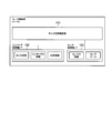
- Drawing 2 is a figure for explaining an example of a functional block of each motor control part of each motor control device which constitutes a motor control system concerning one embodiment.
- FIG. 3 is a diagram for explaining an example of each mapping table managed by the encoder / sensor communication transmission / reception management unit of each motor control device constituting the motor control system according to the embodiment.
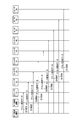
- FIG. 4 is a diagram for explaining an example of a flow of processing executed in the motor control system according to the embodiment.
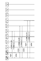
- FIG. 5 is a diagram for explaining an example of a flow of processing executed in the motor control system according to the embodiment.
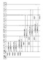
- FIG. 6 is a diagram for explaining an example of a flow of processing executed in the motor control system according to the embodiment.
- FIG. 7 is a diagram for explaining an example of a flow of processing executed in the motor control system according to the embodiment.
- the sensing of the operation status in the motor control system has become increasingly important in recent years.
- the physical cost such as the number of wires, the communication amount or Processing costs such as processing load increase.
- these costs tend to increase.
- a motor control system 1 is configured to control a plurality of motors # 1 to # 6. As illustrated in FIG. 1, as illustrated in FIG. # 1 to # 6, a mechanical device (not shown), encoders # 1 to # 6, and sensors # 7 to # 9.
- the motor control devices # 1 / # 2 are each configured to control at least one of the plurality of motors # 1 to # 6.
- the motor control device # 1 is configured to control the motors # 1 to # 3
- the motor control device # 2 is configured to control the motors # 4 to # 6.
- the present disclosure is not limited to such a case.
- the present invention can be applied to a case where the motor control device # 1 controls the motors # 1 to # 6.
- the motor control devices # 1 / # 2 are devices including computers that control amplifier units that output currents, voltages, and the like to the motors # 1 to # 3 / # 4 to # 6, respectively. That is, the motors # 1 to # 3 / # 4 to # 6 are configured to rotate in accordance with the voltage or current applied from the motor control devices # 1 / # 2, respectively.
- motor control devices # 1 / # 2 for controlling servo motors are called servo controllers or servo amplifiers.
- Motor controller # 1 / # 2 may be any device configured to control a motor, and may be an inverter, for example.
- the motor control device # 1 includes an amplifier unit (not shown), motor control units # 1 to # 3 for controlling the motors # 1 to # 3, encoders, Sensor communication transmission / reception management unit 10, transmission / reception unit # 1 / # 2, and repeater 20 are provided.
- the motor control device # 2 includes an amplifier unit (not shown), motor control units # 4 to # 6 for controlling the motors # 4 to # 6, encoder / sensor communication transmission / reception management unit 10, and transmission / reception. Part # 1 / # 2 and repeater 20 are provided.
- the amplifier unit is a power converter configured to supply currents / voltages based on torque commands from the motor control units # 1 to # 6 to the motors # 1 to # 6.
- each of the motor control devices # 1 / # 2 includes a motor control operation unit 101, an encoder logical axis interface 102, and a sensor logical axis interface 103.
- the motor control calculation unit 101 is configured to receive a command (position command or the like) from the host device and perform a calculation for controlling the position, speed, torque or the like of the motors # 1 to # 6.
- the encoder logical axis interface 102 corresponds to the motor control units # 1 to # 6 to which the encoder logical axis interface 102 belongs based on the mapping table # 1 / # 2 managed by the encoder / sensor communication transmission / reception management unit 10 in the constant reading procedure. At least one of the constants of the motors # 1 to # 6 and the identification information (encoder ID information) of the encoders # 1 to # 6 corresponding to the motors # 1 to # 6 is read.
- the encoder logical axis interface 102 in the position information reading procedure, based on the mapping table # 1 / # 2 managed by the encoder / sensor communication transmission / reception management unit 10, the motor control units # 1 to # 6 to which the encoder logical axis interface 102 belongs. The position information of the motors # 1 to # 6 corresponding to is acquired.
- the encoder logical axis interface 102 of the motor control unit # 1 receives the motor constant and position information of the motor # 1 and the encoder ID information of the encoder # 1 from the encoder / sensor communication transmission / reception management unit 10. Is configured to get.
- the encoder logical axis interface 102 of the motor control unit # 2 is configured to acquire the motor constant and position information of the motor # 2 and the encoder ID information of the encoder # 2 from the encoder / sensor communication transmission / reception management unit 10. Yes.
- the encoder logical axis interface 102 of the motor control unit # 3 is configured to acquire the motor constant and position information of the motor # 3 and the encoder ID information of the encoder # 3 from the encoder / sensor communication transmission / reception management unit 10. Yes.
- the encoder logical axis interface 102 of the motor control unit # 4 is configured to acquire the motor constant and position information of the motor # 4 and the encoder ID information of the encoder # 4 from the encoder / sensor communication transmission / reception management unit 10. Yes.
- the encoder logical axis interface 102 of the motor control unit # 5 is configured to acquire the motor constant and position information of the motor # 5 and the encoder ID information of the encoder # 5 from the encoder / sensor communication transmission / reception management unit 10. Yes.
- the encoder logical axis interface 102 of the motor control unit # 6 is configured to acquire the motor constant and position information of the motor # 6 and the encoder ID information of the encoder # 6 from the encoder / sensor communication transmission / reception management unit 10. Yes.
- the sensor logical axis interface 103 corresponds to the motor control units # 1 to # 6 to which the sensor logical axis interface 103 belongs based on the mapping table # 1 / # 2 managed by the encoder / sensor communication transmission / reception management unit 10 in the constant reading procedure.
- the identification information (sensor ID information) of the sensors # 7 to # 9 corresponding to the motors # 1 to # 6 is read out.
- the sensor logical axis interface 103 uses the motor control units # 1 to # 6 to which the sensor logical axis interface 103 belongs based on the mapping table # 1 / # 2 managed by the encoder / sensor communication transmission / reception management unit 10 in the position information reading procedure.
- the sensor data of the sensors # 7 to # 9 corresponding to the motors # 1 to # 6 corresponding to is read.
- the sensor data includes, for example, ON / OFF information of the sensor itself.
- Encoder / sensor communication transmission / reception management unit 10 is configured to manage communication with motors # 1 to # 6 and sensors # 7 to # 9.
- the encoder / sensor communication transmission / reception management unit 10 is configured to manage the mapping tables shown in FIGS. 3 (a) and 3 (b).
- FIG. 3A shows an example of a mapping table managed by the encoder / sensor communication transmission / reception management unit 10 of the motor control device # 2 in the present embodiment
- FIG. An example of the mapping table managed by the encoder / sensor communication transmission / reception management unit 10 of the motor control device # 1 is shown.
- the mapping table shown in FIG. 3A maps the encoder logical axis interface 102, the motor control device # 4, and the encoder # 4 (communication address of the encoder # 4), and the encoder logical axis interface 102 and the motor control device # 5. And encoder # 5 (communication address of encoder # 5) are mapped, and encoder logical axis interface 102, motor control device # 6, and encoder # 6 (communication address of encoder # 6) are mapped. .
- the mapping table shown in FIG. 3B maps the encoder logical axis interface 102, the motor controller # 1, and the encoder # 1 (communication address of the encoder # 1), and the sensor logical axis interface 103 and the motor controller.
- # 1 and sensor # 9 (communication address of sensor # 9) are mapped
- encoder logical axis interface 102, motor controller # 2 and encoder # 2 (communication address of encoder # 2) are mapped
- sensor logical axis interface 103, motor control device # 2, and sensor # 8 (communication address of sensor # 8) are mapped
- encoder logical axis interface 102, motor control device # 3, and encoder # 3 (communication address of encoder # 3) are mapped.
- Sensor logic axis interface 03 and the motor control device # 3 and the sensor # 7 is set so as to map the (communication address of the sensor # 7).
- mapping table is set in advance by the user, and such setting contents may be configured to be stored in a non-volatile memory (not shown) of the motor control devices # 1 / # 2.
- the encoder / sensor communication transmission / reception management unit 10 is configured to allocate unique communication addresses to the encoders # 1 to # 6 and the sensors # 7 to # 9 based on the above mapping table in the initial communication procedure. Has been.
- the encoder / sensor communication transmission / reception management unit 10 determines the constants of the motors # 1 to # 6, the identification information of the encoders # 1 to # 6, and the sensors # 7 to # 9 based on the mapping table in the constant reading procedure. Is transferred to the corresponding encoder logical axis interface 102 and sensor logical axis interface 103.
- the encoder / sensor communication transmission / reception management unit 10 applies the position information of the motors # 1 to # 6 and the sensor data of the sensors # 7 to # 9 based on the above mapping table in the position information reading procedure.
- the data is transferred to the encoder logical axis interface 102 and the sensor logical axis interface 103.
- the transmission / reception unit # 1 / # 2 is configured to perform data transmission / reception processing with devices (motor control device, encoder, sensor, etc.) other than the motor control device # 1 / # 2 to which the transmission / reception unit # 1 / # 2 belongs.
- the repeater 20 is configured to perform data transfer processing (repeat processing) between the transmission / reception unit # 1 and the transmission / reception unit # 2.
- the encoders # 1 to # 6 are position detectors configured to detect position information of one of the plurality of motors # 1 to # 6 to which the encoders # 1 to # 6 correspond.
- the encoders # 1 to # 6 may be, for example, optical encoders or magnetic encoders.
- the encoders # 1 to # 6 are configured to transmit the position information of the motors # 1 to # 6 to the motor control devices # 1 / # 2, respectively.
- encoders # 1 to # 6 are used as such position detectors
- the present disclosure describes a sensor that can detect position information of motors # 1 to # 6 (
- the present invention can be applied to a case using a resolver or the like.
- the encoders # 1 to # 6 may be linear scales (linear encoders) used when the motors # 1 to # 6 are direct acting motors (linear motors).
- the motors # 1 to # 6 may be rotary motors or linear motion motors (linear motors).
- the position information described above is a rotation angle
- the motors # 1 to # 6 are direct acting motors (linear motors)
- the position information is a linear movement position.
- the above-described mechanical device is configured to be driven by motors # 1 to # 6.
- a robot or the like corresponds to the mechanical device 10A.
- each of the motors # 1 to # 6 is configured to drive each of the axes 1 to 6 of a six-axis robot as a mechanical device.
- the sensors # 7 to # 9 detect information (sensor data) related to at least one of the mechanical devices configured to be driven by the motors # 1 to # 3 and the motors # 1 to # 3. It is configured.
- a temperature sensor a pressure sensor, a torque sensor, a vibration sensor, a limit switch sensor, a touch sensor, an I / O device, or the like is assumed.
- the case where the three sensors # 7 to # 9 are provided has been described as an example.
- the present disclosure includes a case where no sensor is provided or one sensor.
- the present invention can also be applied to a case having four or more sensors.
- FIG. 1 a case where two motor control devices # 1 / # 2 are connected is described as an example.
- the disclosure can also be applied to a case where three or more motor control devices are connected in series.
- the motor control device # 1 sends the motors # 1 to # 6 read from the encoders # 1 to # 6 to the motor control device # 2 (other motor control devices).
- the position information of # 6 is transferred.
- the motor control apparatus # 1 includes at least the motor constants of the motors # 1 to # 3 and the encoder # 1 from the encoders # 1 to # 3 respectively corresponding to the motors # 1 to # 3 controlled by the motor control apparatus # 1. Any one of the encoder ID information of # 3 to # 3 is read out.
- the motor control device # 1 is configured to read the identification information of the sensors # 7 to # 9 from the sensors # 7 to # 9 corresponding to the motors # 1 to # 3 controlled by the motor control device # 1. Has been.
- the motor control device # 2 receives at least the motors # 4 to # 6 from the encoders # 4 to # 6 corresponding to the motors # 4 to # 6 that it controls via the motor control device # 1.
- 6 is configured to read out one of the motor constants 6 and encoder ID information of encoders # 4 to # 6.
- the motor control device # 2 (one of the other motor control devices) operates as a master in the position information reading procedure, and sensors # 7 to # 9 are connected via the motor control device # 1. From this, the identification information (sensor ID information) of the sensors # 7 to # 9 is read out.
- the motor control device # 1 is configured to read the sensor data of the sensors # 7 to # 9 from the sensors # 7 to # 9 corresponding to the motors # 1 to # 3 controlled by the motor control device # 1. ing.
- the motor control device # 2 When sensors corresponding to the motors # 4 to # 6 controlled by the motor control device # 2 exist, the motor control device # 2 sends the sensor to the sensor via the motor control device # 1. The sensor ID information is read out.
- FIGS. 4 shows the flow of processing in the communication initialization procedure in the motor control system 1
- FIGS. 5 and 6 show the flow of processing in the constant reading procedure in the motor control system 1
- FIG. 7 shows the flow of processing in the motor control system 1.
- step S1001 the encoder / sensor communication transmission / reception management unit 10 of the motor control device # 2 performs the transmission / reception unit # 2 of the motor control device # 2, the transmission / reception unit # 1 of the motor control device # 1, and the motor.
- a unique communication address is assigned to encoder # 1 by transmitting address setting data to encoder # 1 via repeater 20 of control device # 1 and transmission / reception unit # 2 of motor control device # 2. .
- step S1002 the encoder / sensor communication transmission / reception management unit 10 of the motor control device # 2 performs the transmission / reception unit # 2 of the motor control device # 2, the transmission / reception unit # 1 of the motor control device # 1, and the repeater 20 of the motor control device # 1. Then, a unique communication address is assigned to the encoder # 2 by transmitting address setting data to the encoder # 2 via the transmission / reception unit # 2 and the encoder # 1 of the motor control device # 2.
- step S1003 the encoder / sensor communication transmission / reception management unit 10 of the motor control device # 2 performs the transmission / reception unit # 2 of the motor control device # 2, the transmission / reception unit # 1 of the motor control device # 1, and the repeater 20 of the motor control device # 1.
- the encoder / sensor communication transmission / reception management unit 10 of the motor control device # 2 performs the transmission / reception unit # 2 of the motor control device # 2, the transmission / reception unit # 1 of the motor control device # 1, and the repeater 20 of the motor control device # 1.
- step S1004 the encoder / sensor communication transmission / reception management unit 10 of the motor control device # 2 performs the transmission / reception unit # 2 of the motor control device # 2, the transmission / reception unit # 1 of the motor control device # 1, and the repeater 20 of the motor control device # 1.
- Unique to encoder # 4 by transmitting address setting data to encoder # 4 via transmission / reception unit # 2, encoder # 1, encoder # 2, and encoder # 3 of motor control device # 2 A valid communication address.
- step S1005 the encoder / sensor communication transmission / reception management unit 10 of the motor control device # 2 performs the transmission / reception unit # 2 of the motor control device # 2, the transmission / reception unit # 1 of the motor control device # 1, and the repeater 20 of the motor control device # 1.
- Encoder # 5 by transmitting address setting data to encoder # 5 via transmission / reception unit # 2, encoder # 1, encoder # 2, encoder # 3, and encoder # 4 of motor control device # 2 Assign a unique communication address.
- step S1006 the encoder / sensor communication transmission / reception management unit 10 of the motor control device # 2 performs the transmission / reception unit # 2 of the motor control device # 2, the transmission / reception unit # 1 of the motor control device # 1, and the repeater 20 of the motor control device # 1.
- address setting data By transmitting address setting data to encoder # 6 via transmission / reception unit # 2, encoder # 1, encoder # 2, encoder # 3, encoder # 4 and encoder # 5 of motor control device # 2 A unique communication address is assigned to encoder # 6.
- step S1007 the encoder / sensor communication transmission / reception management unit 10 of the motor control device # 2 performs the transmission / reception unit # 2 of the motor control device # 2, the transmission / reception unit # 1 of the motor control device # 1, and the repeater 20 of the motor control device # 1.
- Address setting data is sent to sensor # 7 via transmission / reception unit # 2, encoder # 1, encoder # 2, encoder # 3, encoder # 4, encoder # 5, and encoder # 6 of motor control device # 2.
- a unique communication address is assigned to sensor # 7.
- step S1008 the encoder / sensor communication transmission / reception management unit 10 of the motor control device # 2 performs the transmission / reception unit # 2 of the motor control device # 2, the transmission / reception unit # 1 of the motor control device # 1, and the repeater 20 of the motor control device # 1. And to the sensor # 8 via the transmitter / receiver # 2, the encoder # 1, the encoder # 2, the encoder # 3, the encoder # 4, the encoder # 5, the encoder # 6, and the sensor # 7. A unique communication address is assigned to the sensor # 8 by transmitting the address setting data.
- step S1009 the encoder / sensor communication transmission / reception management unit 10 of the motor control device # 2 performs the transmission / reception unit # 2 of the motor control device # 2, the transmission / reception unit # 1 of the motor control device # 1, and the repeater 20 of the motor control device # 1. And sensor # 2 of encoder # 1, encoder # 1, encoder # 2, encoder # 3, encoder # 4, encoder # 5, encoder # 6, sensor # 7, and sensor # 8 of motor control device # 2. By transmitting the address setting data to 9, a unique communication address is assigned to sensor # 9.
- step S2001 the motor control unit # 4 of the motor control device # 2 performs an encoder / sensor communication transmission / reception management unit 10 of the motor control device # 2 and a transmission / reception unit # 2 of the motor control device # 2.
- An ID / constant read request is transmitted to encoder # 4 via transmission / reception unit # 1 of motor control device # 1, repeater 20 of motor control device # 1, and transmission / reception unit # 2 of motor control device # 2.
- step S2002 the encoder # 4 receives the transmission / reception unit # 2 of the motor control device # 2, the repeater 20 of the motor control device # 1, the transmission / reception unit # 1 of the motor control device # 1, and the transmission / reception unit # 2 of the motor control device # 2.
- ID / constant read data (motor constant of motor # 4 and encoder # 4) to motor control unit # 4 of motor control device # 2 via encoder / sensor communication transmission / reception management unit 10 of motor control device # 2.
- Encoder ID information (motor constant of motor # 4 and encoder # 4)
- step S2003 the motor control unit # 5 of the motor control device # 2 transmits / receives the encoder / sensor communication transmission / reception management unit 10 of the motor control device # 2, the transmission / reception unit # 2 of the motor control device # 2, and the motor control device # 1.
- An ID / constant read request is transmitted to encoder # 5 via unit # 1, repeater 20 of motor control device # 1, transmission / reception unit # 2 of motor control device # 2, and encoder # 4.
- the encoder # 5 includes the encoder # 4, the transmission / reception unit # 2 of the motor control device # 2, the repeater 20 of the motor control device # 1, the transmission / reception unit # 1 of the motor control device # 1, and the motor control device # 2.
- ID / constant read data (motor constant of motor # 5) is transmitted to motor control unit # 5 of motor control device # 2 via transmission / reception unit # 2 and encoder / sensor communication transmission / reception management unit 10 of motor control device # 2. Or encoder ID information of encoder # 5).
- step S2005 the motor control unit # 6 of the motor control device # 2 transmits / receives the encoder / sensor communication transmission / reception management unit 10 of the motor control device # 2, the transmission / reception unit # 2 of the motor control device # 2, and the motor control device # 1.
- An ID / constant read request is transmitted to encoder # 6 via unit # 1, repeater 20 of motor control device # 1, transmission / reception unit # 2, motor # 4 and encoder # 5 of motor control device # 2. .
- encoder # 6 is encoder # 5, encoder # 4, transmitter / receiver # 2 of motor controller # 2, repeater 20 of motor controller # 1, transmitter / receiver # 1 of motor controller # 1, and motor control.
- ID / constant read data (motor #) is sent to the motor control unit # 6 of the motor control device # 2 via the transmission / reception unit # 2 of the device # 2 and the encoder / sensor communication transmission / reception management unit 10 of the motor control device # 2. 6 motor constants and encoder ID information of encoder # 6).
- step S3001 the motor control unit # 1 of the motor control device # 1 performs the encoder / sensor communication transmission / reception management unit 10 of the motor control device # 1 and the transmission / reception unit # 2 of the motor control device # 1. Then, an ID / constant read request is transmitted to encoder # 1.
- step S3002 the encoder # 1 is connected to the motor control unit # 1 of the motor control device # 1 via the transmission / reception unit # 2 of the motor control device # 1 and the encoder / sensor communication transmission / reception management unit 10 of the motor control device # 1.
- ID / constant read data (motor constants of motor # 1 and encoder ID information of encoder # 1) are transmitted to.
- step S3003 the motor control unit # 2 of the motor control device # 1 passes through the encoder / sensor communication transmission / reception management unit 10 of the motor control device # 1, the transmission / reception unit # 2 of the motor control device # 1, and the encoder # 1. Then, an ID / constant read request is transmitted to encoder # 2.
- step S3004 the encoder # 2 receives the motor of the motor control device # 1 via the encoder # 1, the transmission / reception unit # 2 of the motor control device # 1, and the encoder / sensor communication transmission / reception management unit 10 of the motor control device # 1.
- ID / constant read data (motor constant of motor # 2 and encoder ID information of encoder # 2) is transmitted to control unit # 2.
- step S3005 the motor control unit # 3 of the motor control device # 1 performs the encoder / sensor communication transmission / reception management unit 10 of the motor control device # 1, the transmission / reception unit # 2, the encoder # 1, and the encoder # 2 of the motor control device # 1. Then, an ID / constant read request is transmitted to encoder # 3.
- step S3006 the encoder # 3 is connected to the motor control device via the encoder # 2, the encoder # 1, the transmission / reception unit # 2 of the motor control device # 1, and the encoder / sensor communication transmission / reception management unit 10 of the motor control device # 1.
- ID / constant read data (motor constant of motor # 3 and encoder ID information of encoder # 3) is transmitted to motor control unit # 3 of # 1.
- step S3007 the motor control unit # 3 of the motor control device # 1 performs the encoder / sensor communication transmission / reception management unit 10 of the motor control device # 1, the transmission / reception unit # 2, the encoder # 1, and the encoder # 2 of the motor control device # 1. Then, an ID / constant read request is transmitted to sensor # 7 via encoder # 3, encoder # 4, encoder # 5, and encoder # 6.
- step S3008 the sensor # 7 receives the encoder # 6, the encoder # 5, the encoder # 4, the encoder # 3, the encoder # 2, the encoder # 1, the transmission / reception unit # 2 of the motor control device # 1, and the motor control device # 1.
- ID / constant read data (sensor ID information of sensor # 7) is transmitted to the motor control unit # 3 of the motor control device # 1 via the encoder / sensor communication transmission / reception management unit 10.
- step S3009 the motor control unit # 2 of the motor control device # 1 performs the encoder / sensor communication transmission / reception management unit 10 of the motor control device # 1, the transmission / reception unit # 2, the encoder # 1, and the encoder # 2 of the motor control device # 1.
- ID / constant read request is transmitted to sensor # 8 via encoder # 3, encoder # 4, encoder # 5, encoder # 6, and sensor # 7.
- the sensor # 8 includes the sensor # 7, the encoder # 6, the encoder # 5, the encoder # 4, the encoder # 3, the encoder # 2, the encoder # 1, the transmission / reception unit # 2 of the motor control device # 1, and the motor control.
- ID / constant read data (sensor ID information of sensor # 8) is transmitted to the motor control unit # 2 of the motor control device # 1 via the encoder / sensor communication transmission / reception management unit 10 of the device # 1.
- step S3011 the motor control unit # 1 of the motor control device # 1 performs the encoder / sensor communication transmission / reception management unit 10 of the motor control device # 1, the transmission / reception unit # 2, the encoder # 1, and the encoder # 2 of the motor control device # 1.
- ID / constant read request is transmitted to sensor # 9 via encoder # 3, encoder # 4, encoder # 5, encoder # 6, sensor # 7 and sensor # 8.
- sensor # 9 is a sensor # 8, sensor # 7, encoder # 6, encoder # 5, encoder # 4, encoder # 3, encoder # 2, encoder # 1, and transmission / reception unit # of motor control device # 1. 2 and ID / constant read data (sensor ID information of sensor # 9) to motor control unit # 1 of motor control device # 1 via encoder / sensor communication transmission / reception management unit 10 of motor control device # 1. Send.
- the motor control device # 1 becomes the master, and before such processing is started, the transmission / reception unit # of the motor control device # 1 is executed. 1 stops and the repeater 20 of the motor control device # 1 is turned OFF. During this period (until motor control device # 1 completes all constant reading procedures), motor control device # 2 is in a reception standby state for the position information of motors # 4 to # 6.
- the position information reading procedure (normal mode) in the motor control system 1 will be described.
- the motor control device # 2 becomes the master, and the motor control device # 1 is configured by the motor control device # 2 and the encoders # 1 to # 6.
- the monitor mode in which only data transmitted from the sensors # 7 to # 9 can be monitored is set, and the repeater 20 of the motor control device # 1 is turned on.
- step S4001 the encoder / sensor communication transmission / reception management unit 10 of the motor control device # 2 performs the transmission / reception unit # 2 of the motor control device # 2, the transmission / reception unit # 1 of the motor control device # 1, and the motor.
- a position information acquisition request is broadcast to encoders # 1 to # 6 and sensors # 7 to # 9 via repeater 20 of control device # 1 and transmission / reception unit # 2 of motor control device # 1.
- step S4002 encoder # 1 transmits / receives # 2 of motor controller # 1, repeater 20 of motor controller # 1, transmitter / receiver # 1 of motor controller # 1, and transmitter / receiver # 2 of motor controller # 2. And the position information of the motor # 1 is transmitted to the motor control unit # 1 via the encoder / sensor communication transmission / reception management unit 10 of the motor control device # 2.
- the motor control device # 1 refers to the mapping table # 1 (see FIG. 3B) managed by its encoder / sensor communication transmission / reception management unit 10, and the monitored data is Is the position information of the encoder # 1 corresponding to the motor # 1 to be controlled. Therefore, the position information of the encoder # 1 is fetched.
- the encoder # 2 includes the encoder # 1, the transmission / reception unit # 2 of the motor control device # 1, the repeater 20 of the motor control device # 1, the transmission / reception unit # 1 of the motor control device # 1, and the motor control device # 2.
- the position information of the motor # 2 is transmitted to the motor control unit # 2 via the transmission / reception unit # 2 and the encoder / sensor communication transmission / reception management unit 10 of the motor control device # 2.
- the motor control device # 1 refers to the mapping table # 1 (see FIG. 3B) managed by its encoder / sensor communication transmission / reception management unit 10, and the monitored data is Is the position information of the encoder # 2 corresponding to the motor # 2 to be controlled. Therefore, the position information of the encoder # 2 is fetched.
- encoder # 3 is encoder # 2, encoder 1, transmitter / receiver # 2 of motor controller # 1, repeater 20 of motor controller # 1, transmitter / receiver # 1 of motor controller # 1, and motor controller.
- the position information of the motor # 3 is transmitted to the motor control unit # 3 via the # 2 transmission / reception unit # 2 and the encoder / sensor communication transmission / reception management unit 10 of the motor control device # 2.
- the motor control device # 1 refers to the mapping table # 1 (see FIG. 3B) managed by its encoder / sensor communication transmission / reception management unit 10, and the monitored data is Is the position information of the encoder # 3 corresponding to the motor # 3 to be controlled, so the position information of the encoder # 3 is fetched.
- encoder # 4 is encoder # 3, encoder # 2, encoder 1, transmitter / receiver # 2 of motor controller # 1, repeater 20 of motor controller # 1, and transmitter / receiver # 1 of motor controller # 1.
- the position information of the motor # 4 is transmitted to the motor control unit # 4 via the transmission / reception unit # 2 of the motor control device # 2 and the encoder / sensor communication transmission / reception management unit 10 of the motor control device # 2.
- the encoder # 5 includes the encoder # 4, the encoder # 3, the encoder # 2, the encoder 1, the transmission / reception unit # 2 of the motor control device # 1, the repeater 20 of the motor control device # 1, and the motor control device # 1. Position information of the motor # 5 is transmitted to the motor control unit # 5 via the transmission / reception unit # 1, the transmission / reception unit # 2 of the motor control device # 2, and the encoder / sensor communication transmission / reception management unit 10 of the motor control device # 2. Send.
- encoder # 6 is encoder # 5, encoder # 4, encoder # 3, encoder # 2, encoder 1, transmitter / receiver # 2 of motor controller # 1, repeater 20 of motor controller # 1, and motor control.
- the motor # 6 is transmitted to the motor control unit # 6 via the transmission / reception unit # 1 of the device # 1, the transmission / reception unit # 2 of the motor control device # 2, and the encoder / sensor communication transmission / reception management unit 10 of the motor control device # 2.
- sensor # 7 includes encoder # 6, encoder # 5, encoder # 4, encoder # 3, encoder # 2, encoder 1, transmitter / receiver # 2 of motor controller # 1, and repeater of motor controller # 1. 20 to the motor control unit # 3 via the transmission / reception unit # 1 of the motor control device # 1, the transmission / reception unit # 2 of the motor control device # 2, and the encoder / sensor communication transmission / reception management unit 10 of the motor control device # 2. Sensor # 7 sensor data is transmitted.
- sensor # 8 includes sensor # 7, encoder # 6, encoder # 5, encoder # 4, encoder # 3, encoder # 2, encoder 1, transmission / reception unit # 2 of motor control device # 1, and motor control device.
- the motor control unit via the # 1 repeater 20, the transmission / reception unit # 1 of the motor control device # 1, the transmission / reception unit # 2 of the motor control device # 2, and the encoder / sensor communication transmission / reception management unit 10 of the motor control device # 2.
- the sensor data of sensor # 8 is transmitted to # 2.
- step S4010 sensor # 9 is sensor # 8, sensor # 7, encoder # 6, encoder # 5, encoder # 4, encoder # 3, encoder # 2, encoder 1, and transmission / reception unit # 2 of motor control device # 1. And repeater 20 of motor control device # 1, transmission / reception unit # 1 of motor control device # 1, transmission / reception unit # 2 of motor control device # 2, and encoder / sensor communication transmission / reception management unit 10 of motor control device # 2. Then, the sensor data of sensor # 9 is transmitted to motor control unit # 1.
- a plurality of encoders are connected in series under the control unit # 1 of the motor control device 20 so that the control unit # 1 and the control unit # 2 are connected. Even if it is comprised, the setting procedure of the motor control apparatus 20 can be implement
- the encoders # 1 to # 6 (and the mechanical devices driven by the motors # 1 to # 6) and the motor control device # 1 / # installed in the control panel.
- the processing load distribution of the motor control process # 1 / # 2 can be realized while reducing the number of wirings between the two.
Landscapes
- Engineering & Computer Science (AREA)
- Power Engineering (AREA)
- Human Computer Interaction (AREA)
- Manufacturing & Machinery (AREA)
- Physics & Mathematics (AREA)
- General Physics & Mathematics (AREA)
- Automation & Control Theory (AREA)
- Control Of Multiple Motors (AREA)
Priority Applications (5)
| Application Number | Priority Date | Filing Date | Title |
|---|---|---|---|
| PCT/JP2017/013359 WO2018179268A1 (ja) | 2017-03-30 | 2017-03-30 | モータ制御システム、制御方法及びモータ制御装置 |
| JP2017536035A JP6241578B1 (ja) | 2017-03-30 | 2017-03-30 | モータ制御システム、制御方法及びモータ制御装置 |
| CN201780089105.0A CN110495091B (zh) | 2017-03-30 | 2017-03-30 | 马达控制系统、控制方法以及马达控制装置 |
| EP17904022.5A EP3605827B1 (en) | 2017-03-30 | 2017-03-30 | Motor control system, control method, and motor control device |
| US16/587,061 US11181881B2 (en) | 2017-03-30 | 2019-09-30 | Motor control system, control method, and motor control apparatus |
Applications Claiming Priority (1)
| Application Number | Priority Date | Filing Date | Title |
|---|---|---|---|
| PCT/JP2017/013359 WO2018179268A1 (ja) | 2017-03-30 | 2017-03-30 | モータ制御システム、制御方法及びモータ制御装置 |
Related Child Applications (1)
| Application Number | Title | Priority Date | Filing Date |
|---|---|---|---|
| US16/587,061 Continuation US11181881B2 (en) | 2017-03-30 | 2019-09-30 | Motor control system, control method, and motor control apparatus |
Publications (1)
| Publication Number | Publication Date |
|---|---|
| WO2018179268A1 true WO2018179268A1 (ja) | 2018-10-04 |
Family
ID=60570285
Family Applications (1)
| Application Number | Title | Priority Date | Filing Date |
|---|---|---|---|
| PCT/JP2017/013359 WO2018179268A1 (ja) | 2017-03-30 | 2017-03-30 | モータ制御システム、制御方法及びモータ制御装置 |
Country Status (5)
| Country | Link |
|---|---|
| US (1) | US11181881B2 (zh) |
| EP (1) | EP3605827B1 (zh) |
| JP (1) | JP6241578B1 (zh) |
| CN (1) | CN110495091B (zh) |
| WO (1) | WO2018179268A1 (zh) |
Cited By (1)
| Publication number | Priority date | Publication date | Assignee | Title |
|---|---|---|---|---|
| WO2023189134A1 (ja) * | 2022-04-01 | 2023-10-05 | オムロン株式会社 | ドライブシステム |
Families Citing this family (1)
| Publication number | Priority date | Publication date | Assignee | Title |
|---|---|---|---|---|
| CN112894764A (zh) * | 2019-12-03 | 2021-06-04 | 台达电子工业股份有限公司 | 机械手臂系统及机械手臂控制方法 |
Citations (5)
| Publication number | Priority date | Publication date | Assignee | Title |
|---|---|---|---|---|
| JPH08241111A (ja) | 1995-03-03 | 1996-09-17 | Mitsubishi Electric Corp | 駆動制御システム |
| JPH10105206A (ja) | 1996-10-02 | 1998-04-24 | Mitsubishi Electric Corp | サーボモータの駆動制御装置およびサーボアンプ、周辺装置、サーボモータの位置検出器 |
| JP2007181340A (ja) * | 2005-12-28 | 2007-07-12 | Yaskawa Electric Corp | サーボシステムおよびサーボドライブ |
| JP2008090825A (ja) * | 2006-09-08 | 2008-04-17 | Yaskawa Electric Corp | 位置検出器をマルチドロップ接続した多軸制御システム |
| WO2016042636A1 (ja) * | 2014-09-18 | 2016-03-24 | 株式会社安川電機 | エンコーダシステム及びセンサシステム |
Family Cites Families (6)
| Publication number | Priority date | Publication date | Assignee | Title |
|---|---|---|---|---|
| JP2004280506A (ja) * | 2003-03-17 | 2004-10-07 | Fanuc Ltd | 数値制御装置 |
| KR100752049B1 (ko) * | 2006-08-26 | 2007-08-27 | (주)대봉기연 | 소재자동이송식 프레스 텐덤라인의 적응적 동기화 제어방법 |
| JP4853842B2 (ja) * | 2010-01-12 | 2012-01-11 | 株式会社安川電機 | 同期制御装置 |
| CN103609014B (zh) * | 2011-06-14 | 2016-06-15 | 株式会社安川电机 | 多轴马达驱动系统以及多轴马达驱动装置 |
| JP6313642B2 (ja) * | 2014-04-18 | 2018-04-18 | キヤノン株式会社 | リニアモータ制御装置及びリニアモータ制御システム |
| JP6165286B1 (ja) * | 2016-02-29 | 2017-07-19 | 株式会社安川電機 | モータ制御システム、ロボットシステム、及びモータ制御システムの通信方法 |
-
2017
- 2017-03-30 CN CN201780089105.0A patent/CN110495091B/zh active Active
- 2017-03-30 JP JP2017536035A patent/JP6241578B1/ja active Active
- 2017-03-30 EP EP17904022.5A patent/EP3605827B1/en active Active
- 2017-03-30 WO PCT/JP2017/013359 patent/WO2018179268A1/ja unknown
-
2019
- 2019-09-30 US US16/587,061 patent/US11181881B2/en active Active
Patent Citations (5)
| Publication number | Priority date | Publication date | Assignee | Title |
|---|---|---|---|---|
| JPH08241111A (ja) | 1995-03-03 | 1996-09-17 | Mitsubishi Electric Corp | 駆動制御システム |
| JPH10105206A (ja) | 1996-10-02 | 1998-04-24 | Mitsubishi Electric Corp | サーボモータの駆動制御装置およびサーボアンプ、周辺装置、サーボモータの位置検出器 |
| JP2007181340A (ja) * | 2005-12-28 | 2007-07-12 | Yaskawa Electric Corp | サーボシステムおよびサーボドライブ |
| JP2008090825A (ja) * | 2006-09-08 | 2008-04-17 | Yaskawa Electric Corp | 位置検出器をマルチドロップ接続した多軸制御システム |
| WO2016042636A1 (ja) * | 2014-09-18 | 2016-03-24 | 株式会社安川電機 | エンコーダシステム及びセンサシステム |
Non-Patent Citations (1)
| Title |
|---|
| See also references of EP3605827A4 |
Cited By (1)
| Publication number | Priority date | Publication date | Assignee | Title |
|---|---|---|---|---|
| WO2023189134A1 (ja) * | 2022-04-01 | 2023-10-05 | オムロン株式会社 | ドライブシステム |
Also Published As
| Publication number | Publication date |
|---|---|
| EP3605827A1 (en) | 2020-02-05 |
| EP3605827B1 (en) | 2023-05-03 |
| JPWO2018179268A1 (ja) | 2019-04-04 |
| US11181881B2 (en) | 2021-11-23 |
| CN110495091A (zh) | 2019-11-22 |
| EP3605827A4 (en) | 2020-11-25 |
| JP6241578B1 (ja) | 2017-12-06 |
| CN110495091B (zh) | 2023-01-20 |
| US20200089187A1 (en) | 2020-03-19 |
Similar Documents
| Publication | Publication Date | Title |
|---|---|---|
| CN101939220B (zh) | 分布式飞行控制系统 | |
| JP6241578B1 (ja) | モータ制御システム、制御方法及びモータ制御装置 | |
| CN102959853B (zh) | 交流旋转机控制设备 | |
| CN108569333A (zh) | 线控转向系统和用于在线控转向系统中的数据交换的方法 | |
| CN101421082B (zh) | 工业机器人系统的多输入控制 | |
| US20110213586A1 (en) | Device and Method for Transmitting Data Between a Position-Measuring Device and Sequential Electronics | |
| US10406682B2 (en) | Motor operation control system, multi-axis mechanical apparatus, and motor operation control method | |
| US11986961B2 (en) | Machine learning model operation management system and machine learning model operation management method | |
| JP2011113415A (ja) | 制御システム及びcpuユニット | |
| US6396030B1 (en) | Robot control device | |
| US20060168358A1 (en) | Storage control system | |
| US6522096B1 (en) | Control circuit for a robot power supply | |
| CN102402489B (zh) | 电子设备及其控制方法 | |
| US20160134475A1 (en) | Control system, master station, and remote station | |
| CN101826061A (zh) | 硬件装置的共享系统与管理方法 | |
| US8539122B2 (en) | Submodule and method for exchanging peripheral data | |
| EP1775686B1 (en) | Occupation monitoring system | |
| KR20140002254A (ko) | 피엘씨 통신 수행 장치 및 방법 | |
| KR101932480B1 (ko) | 차량용 can 통신 장치 | |
| WO2015081316A1 (en) | Enabling communication between devices using splitter cables | |
| JP5107153B2 (ja) | プログラマブルコントローラシステム | |
| US8874401B2 (en) | Process and device for the parameterization of measuring device | |
| JP5640941B2 (ja) | プロセスデータモニタシステム | |
| US11316461B2 (en) | Motor control apparatus, motor control method, and motor control system | |
| JP5910694B2 (ja) | 交流回転機の制御装置 |
Legal Events
| Date | Code | Title | Description |
|---|---|---|---|
| ENP | Entry into the national phase |
Ref document number: 2017536035 Country of ref document: JP Kind code of ref document: A |
|
| 121 | Ep: the epo has been informed by wipo that ep was designated in this application |
Ref document number: 17904022 Country of ref document: EP Kind code of ref document: A1 |
|
| NENP | Non-entry into the national phase |
Ref country code: DE |
|
| ENP | Entry into the national phase |
Ref document number: 2017904022 Country of ref document: EP Effective date: 20191030 |