WO2018179268A1 - モータ制御システム、制御方法及びモータ制御装置 - Google Patents
モータ制御システム、制御方法及びモータ制御装置 Download PDFInfo
- Publication number
- WO2018179268A1 WO2018179268A1 PCT/JP2017/013359 JP2017013359W WO2018179268A1 WO 2018179268 A1 WO2018179268 A1 WO 2018179268A1 JP 2017013359 W JP2017013359 W JP 2017013359W WO 2018179268 A1 WO2018179268 A1 WO 2018179268A1
- Authority
- WO
- WIPO (PCT)
- Prior art keywords
- motor control
- encoder
- control device
- motor
- motors
- Prior art date
Links
Images


Classifications
-
- H—ELECTRICITY
- H02—GENERATION; CONVERSION OR DISTRIBUTION OF ELECTRIC POWER
- H02P—CONTROL OR REGULATION OF ELECTRIC MOTORS, ELECTRIC GENERATORS OR DYNAMO-ELECTRIC CONVERTERS; CONTROLLING TRANSFORMERS, REACTORS OR CHOKE COILS
- H02P23/00—Arrangements or methods for the control of AC motors characterised by a control method other than vector control
- H02P23/0077—Characterised by the use of a particular software algorithm
-
- G—PHYSICS
- G05—CONTROLLING; REGULATING
- G05B—CONTROL OR REGULATING SYSTEMS IN GENERAL; FUNCTIONAL ELEMENTS OF SUCH SYSTEMS; MONITORING OR TESTING ARRANGEMENTS FOR SUCH SYSTEMS OR ELEMENTS
- G05B19/00—Programme-control systems
- G05B19/02—Programme-control systems electric
- G05B19/18—Numerical control [NC], i.e. automatically operating machines, in particular machine tools, e.g. in a manufacturing environment, so as to execute positioning, movement or co-ordinated operations by means of programme data in numerical form
- G05B19/19—Numerical control [NC], i.e. automatically operating machines, in particular machine tools, e.g. in a manufacturing environment, so as to execute positioning, movement or co-ordinated operations by means of programme data in numerical form characterised by positioning or contouring control systems, e.g. to control position from one programmed point to another or to control movement along a programmed continuous path
- G05B19/21—Numerical control [NC], i.e. automatically operating machines, in particular machine tools, e.g. in a manufacturing environment, so as to execute positioning, movement or co-ordinated operations by means of programme data in numerical form characterised by positioning or contouring control systems, e.g. to control position from one programmed point to another or to control movement along a programmed continuous path using an incremental digital measuring device
-
- H—ELECTRICITY
- H02—GENERATION; CONVERSION OR DISTRIBUTION OF ELECTRIC POWER
- H02P—CONTROL OR REGULATION OF ELECTRIC MOTORS, ELECTRIC GENERATORS OR DYNAMO-ELECTRIC CONVERTERS; CONTROLLING TRANSFORMERS, REACTORS OR CHOKE COILS
- H02P5/00—Arrangements specially adapted for regulating or controlling the speed or torque of two or more electric motors
- H02P5/46—Arrangements specially adapted for regulating or controlling the speed or torque of two or more electric motors for speed regulation of two or more dynamo-electric motors in relation to one another
-
- H—ELECTRICITY
- H02—GENERATION; CONVERSION OR DISTRIBUTION OF ELECTRIC POWER
- H02P—CONTROL OR REGULATION OF ELECTRIC MOTORS, ELECTRIC GENERATORS OR DYNAMO-ELECTRIC CONVERTERS; CONTROLLING TRANSFORMERS, REACTORS OR CHOKE COILS
- H02P6/00—Arrangements for controlling synchronous motors or other dynamo-electric motors using electronic commutation dependent on the rotor position; Electronic commutators therefor
- H02P6/04—Arrangements for controlling or regulating the speed or torque of more than one motor
-
- G—PHYSICS
- G05—CONTROLLING; REGULATING
- G05B—CONTROL OR REGULATING SYSTEMS IN GENERAL; FUNCTIONAL ELEMENTS OF SUCH SYSTEMS; MONITORING OR TESTING ARRANGEMENTS FOR SUCH SYSTEMS OR ELEMENTS
- G05B2219/00—Program-control systems
- G05B2219/20—Pc systems
- G05B2219/22—Pc multi processor system
- G05B2219/2214—Multicontrollers, multimicrocomputers, multiprocessing
Definitions
- the present disclosure relates to a motor control system, a control method, and a motor control device.
- Patent Document 1 a plurality of sensors are connected to an interface unit through separate communication paths, and detection signals from each sensor are transmitted via a network connecting a host controller and a motor control device. A system is described that is transmitted to the motor controller.
- Patent Document 2 describes a system for connecting peripheral devices for setting and monitoring parameters of a motor control device via a communication unit in the motor control device.
- JP-A-8-241111 Japanese Patent Laid-Open No. 10-105206
- the present disclosure has been made in view of the above-described problems, and an object thereof is to provide a motor control system, a control method, and a motor control device that can reduce physical or processing costs.
- a first feature of the present disclosure is a motor control system configured to control a plurality of motors, each of which is configured to control at least one of the plurality of motors. And a plurality of position detectors configured to detect position information of one of the plurality of motors to which each corresponds, the plurality of motor control apparatuses
- the plurality of position detectors are all connected in series under the first motor control device included in the first motor control device, and the first motor control device is included in the plurality of motor control devices.
- the gist is that the position information of the plurality of motors read from the plurality of position detectors is transferred to another motor control device.
- a second feature of the present disclosure is a control method in a motor control system configured to control a plurality of motors, wherein each of the plurality of motor control devices is at least one of the plurality of motors.
- a plurality of position detectors each of which detects position information of one of the plurality of motors corresponding to the plurality of position detectors, and a first motor included in the plurality of motor control devices Position information of the plurality of motors read out from all of the plurality of position detectors connected in series under the control of another motor control device included in the plurality of motor control devices by the control device And a step of transferring the content.
- a third feature of the present disclosure is a motor control device used in a motor control system configured to control a plurality of motors, and configured to control at least one of the plurality of motors.
- a plurality of position detectors configured to detect position information of one of the plurality of corresponding motors are connected in series to each other, and the other The gist is that the position information of the plurality of motors read from the plurality of position detectors is transferred to the motor control device.
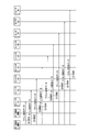
- FIG. 1 is a diagram for explaining an example of an overall schematic configuration of a motor control system according to an embodiment.
- Drawing 2 is a figure for explaining an example of a functional block of each motor control part of each motor control device which constitutes a motor control system concerning one embodiment.
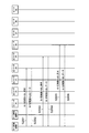
- FIG. 3 is a diagram for explaining an example of each mapping table managed by the encoder / sensor communication transmission / reception management unit of each motor control device constituting the motor control system according to the embodiment.
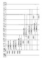
- FIG. 4 is a diagram for explaining an example of a flow of processing executed in the motor control system according to the embodiment.
- FIG. 5 is a diagram for explaining an example of a flow of processing executed in the motor control system according to the embodiment.
- FIG. 6 is a diagram for explaining an example of a flow of processing executed in the motor control system according to the embodiment.
- FIG. 7 is a diagram for explaining an example of a flow of processing executed in the motor control system according to the embodiment.
- the sensing of the operation status in the motor control system has become increasingly important in recent years.
- the physical cost such as the number of wires, the communication amount or Processing costs such as processing load increase.
- these costs tend to increase.
- a motor control system 1 is configured to control a plurality of motors # 1 to # 6. As illustrated in FIG. 1, as illustrated in FIG. # 1 to # 6, a mechanical device (not shown), encoders # 1 to # 6, and sensors # 7 to # 9.
- the motor control devices # 1 / # 2 are each configured to control at least one of the plurality of motors # 1 to # 6.
- the motor control device # 1 is configured to control the motors # 1 to # 3
- the motor control device # 2 is configured to control the motors # 4 to # 6.
- the present disclosure is not limited to such a case.
- the present invention can be applied to a case where the motor control device # 1 controls the motors # 1 to # 6.
- the motor control devices # 1 / # 2 are devices including computers that control amplifier units that output currents, voltages, and the like to the motors # 1 to # 3 / # 4 to # 6, respectively. That is, the motors # 1 to # 3 / # 4 to # 6 are configured to rotate in accordance with the voltage or current applied from the motor control devices # 1 / # 2, respectively.
- motor control devices # 1 / # 2 for controlling servo motors are called servo controllers or servo amplifiers.
- Motor controller # 1 / # 2 may be any device configured to control a motor, and may be an inverter, for example.
- the motor control device # 1 includes an amplifier unit (not shown), motor control units # 1 to # 3 for controlling the motors # 1 to # 3, encoders, Sensor communication transmission / reception management unit 10, transmission / reception unit # 1 / # 2, and repeater 20 are provided.
- the motor control device # 2 includes an amplifier unit (not shown), motor control units # 4 to # 6 for controlling the motors # 4 to # 6, encoder / sensor communication transmission / reception management unit 10, and transmission / reception. Part # 1 / # 2 and repeater 20 are provided.
- the amplifier unit is a power converter configured to supply currents / voltages based on torque commands from the motor control units # 1 to # 6 to the motors # 1 to # 6.
- each of the motor control devices # 1 / # 2 includes a motor control operation unit 101, an encoder logical axis interface 102, and a sensor logical axis interface 103.
- the motor control calculation unit 101 is configured to receive a command (position command or the like) from the host device and perform a calculation for controlling the position, speed, torque or the like of the motors # 1 to # 6.
- the encoder logical axis interface 102 corresponds to the motor control units # 1 to # 6 to which the encoder logical axis interface 102 belongs based on the mapping table # 1 / # 2 managed by the encoder / sensor communication transmission / reception management unit 10 in the constant reading procedure. At least one of the constants of the motors # 1 to # 6 and the identification information (encoder ID information) of the encoders # 1 to # 6 corresponding to the motors # 1 to # 6 is read.
- the encoder logical axis interface 102 in the position information reading procedure, based on the mapping table # 1 / # 2 managed by the encoder / sensor communication transmission / reception management unit 10, the motor control units # 1 to # 6 to which the encoder logical axis interface 102 belongs. The position information of the motors # 1 to # 6 corresponding to is acquired.
- the encoder logical axis interface 102 of the motor control unit # 1 receives the motor constant and position information of the motor # 1 and the encoder ID information of the encoder # 1 from the encoder / sensor communication transmission / reception management unit 10. Is configured to get.
- the encoder logical axis interface 102 of the motor control unit # 2 is configured to acquire the motor constant and position information of the motor # 2 and the encoder ID information of the encoder # 2 from the encoder / sensor communication transmission / reception management unit 10. Yes.
- the encoder logical axis interface 102 of the motor control unit # 3 is configured to acquire the motor constant and position information of the motor # 3 and the encoder ID information of the encoder # 3 from the encoder / sensor communication transmission / reception management unit 10. Yes.
- the encoder logical axis interface 102 of the motor control unit # 4 is configured to acquire the motor constant and position information of the motor # 4 and the encoder ID information of the encoder # 4 from the encoder / sensor communication transmission / reception management unit 10. Yes.
- the encoder logical axis interface 102 of the motor control unit # 5 is configured to acquire the motor constant and position information of the motor # 5 and the encoder ID information of the encoder # 5 from the encoder / sensor communication transmission / reception management unit 10. Yes.
- the encoder logical axis interface 102 of the motor control unit # 6 is configured to acquire the motor constant and position information of the motor # 6 and the encoder ID information of the encoder # 6 from the encoder / sensor communication transmission / reception management unit 10. Yes.
- the sensor logical axis interface 103 corresponds to the motor control units # 1 to # 6 to which the sensor logical axis interface 103 belongs based on the mapping table # 1 / # 2 managed by the encoder / sensor communication transmission / reception management unit 10 in the constant reading procedure.
- the identification information (sensor ID information) of the sensors # 7 to # 9 corresponding to the motors # 1 to # 6 is read out.
- the sensor logical axis interface 103 uses the motor control units # 1 to # 6 to which the sensor logical axis interface 103 belongs based on the mapping table # 1 / # 2 managed by the encoder / sensor communication transmission / reception management unit 10 in the position information reading procedure.
- the sensor data of the sensors # 7 to # 9 corresponding to the motors # 1 to # 6 corresponding to is read.
- the sensor data includes, for example, ON / OFF information of the sensor itself.
- Encoder / sensor communication transmission / reception management unit 10 is configured to manage communication with motors # 1 to # 6 and sensors # 7 to # 9.
- the encoder / sensor communication transmission / reception management unit 10 is configured to manage the mapping tables shown in FIGS. 3 (a) and 3 (b).
- FIG. 3A shows an example of a mapping table managed by the encoder / sensor communication transmission / reception management unit 10 of the motor control device # 2 in the present embodiment
- FIG. An example of the mapping table managed by the encoder / sensor communication transmission / reception management unit 10 of the motor control device # 1 is shown.
- the mapping table shown in FIG. 3A maps the encoder logical axis interface 102, the motor control device # 4, and the encoder # 4 (communication address of the encoder # 4), and the encoder logical axis interface 102 and the motor control device # 5. And encoder # 5 (communication address of encoder # 5) are mapped, and encoder logical axis interface 102, motor control device # 6, and encoder # 6 (communication address of encoder # 6) are mapped. .
- the mapping table shown in FIG. 3B maps the encoder logical axis interface 102, the motor controller # 1, and the encoder # 1 (communication address of the encoder # 1), and the sensor logical axis interface 103 and the motor controller.
- # 1 and sensor # 9 (communication address of sensor # 9) are mapped
- encoder logical axis interface 102, motor controller # 2 and encoder # 2 (communication address of encoder # 2) are mapped
- sensor logical axis interface 103, motor control device # 2, and sensor # 8 (communication address of sensor # 8) are mapped
- encoder logical axis interface 102, motor control device # 3, and encoder # 3 (communication address of encoder # 3) are mapped.
- Sensor logic axis interface 03 and the motor control device # 3 and the sensor # 7 is set so as to map the (communication address of the sensor # 7).
- mapping table is set in advance by the user, and such setting contents may be configured to be stored in a non-volatile memory (not shown) of the motor control devices # 1 / # 2.
- the encoder / sensor communication transmission / reception management unit 10 is configured to allocate unique communication addresses to the encoders # 1 to # 6 and the sensors # 7 to # 9 based on the above mapping table in the initial communication procedure. Has been.
- the encoder / sensor communication transmission / reception management unit 10 determines the constants of the motors # 1 to # 6, the identification information of the encoders # 1 to # 6, and the sensors # 7 to # 9 based on the mapping table in the constant reading procedure. Is transferred to the corresponding encoder logical axis interface 102 and sensor logical axis interface 103.
- the encoder / sensor communication transmission / reception management unit 10 applies the position information of the motors # 1 to # 6 and the sensor data of the sensors # 7 to # 9 based on the above mapping table in the position information reading procedure.
- the data is transferred to the encoder logical axis interface 102 and the sensor logical axis interface 103.
- the transmission / reception unit # 1 / # 2 is configured to perform data transmission / reception processing with devices (motor control device, encoder, sensor, etc.) other than the motor control device # 1 / # 2 to which the transmission / reception unit # 1 / # 2 belongs.
- the repeater 20 is configured to perform data transfer processing (repeat processing) between the transmission / reception unit # 1 and the transmission / reception unit # 2.
- the encoders # 1 to # 6 are position detectors configured to detect position information of one of the plurality of motors # 1 to # 6 to which the encoders # 1 to # 6 correspond.
- the encoders # 1 to # 6 may be, for example, optical encoders or magnetic encoders.
- the encoders # 1 to # 6 are configured to transmit the position information of the motors # 1 to # 6 to the motor control devices # 1 / # 2, respectively.
- encoders # 1 to # 6 are used as such position detectors
- the present disclosure describes a sensor that can detect position information of motors # 1 to # 6 (
- the present invention can be applied to a case using a resolver or the like.
- the encoders # 1 to # 6 may be linear scales (linear encoders) used when the motors # 1 to # 6 are direct acting motors (linear motors).
- the motors # 1 to # 6 may be rotary motors or linear motion motors (linear motors).
- the position information described above is a rotation angle
- the motors # 1 to # 6 are direct acting motors (linear motors)
- the position information is a linear movement position.
- the above-described mechanical device is configured to be driven by motors # 1 to # 6.
- a robot or the like corresponds to the mechanical device 10A.
- each of the motors # 1 to # 6 is configured to drive each of the axes 1 to 6 of a six-axis robot as a mechanical device.
- the sensors # 7 to # 9 detect information (sensor data) related to at least one of the mechanical devices configured to be driven by the motors # 1 to # 3 and the motors # 1 to # 3. It is configured.
- a temperature sensor a pressure sensor, a torque sensor, a vibration sensor, a limit switch sensor, a touch sensor, an I / O device, or the like is assumed.
- the case where the three sensors # 7 to # 9 are provided has been described as an example.
- the present disclosure includes a case where no sensor is provided or one sensor.
- the present invention can also be applied to a case having four or more sensors.
- FIG. 1 a case where two motor control devices # 1 / # 2 are connected is described as an example.
- the disclosure can also be applied to a case where three or more motor control devices are connected in series.
- the motor control device # 1 sends the motors # 1 to # 6 read from the encoders # 1 to # 6 to the motor control device # 2 (other motor control devices).
- the position information of # 6 is transferred.
- the motor control apparatus # 1 includes at least the motor constants of the motors # 1 to # 3 and the encoder # 1 from the encoders # 1 to # 3 respectively corresponding to the motors # 1 to # 3 controlled by the motor control apparatus # 1. Any one of the encoder ID information of # 3 to # 3 is read out.
- the motor control device # 1 is configured to read the identification information of the sensors # 7 to # 9 from the sensors # 7 to # 9 corresponding to the motors # 1 to # 3 controlled by the motor control device # 1. Has been.
- the motor control device # 2 receives at least the motors # 4 to # 6 from the encoders # 4 to # 6 corresponding to the motors # 4 to # 6 that it controls via the motor control device # 1.
- 6 is configured to read out one of the motor constants 6 and encoder ID information of encoders # 4 to # 6.
- the motor control device # 2 (one of the other motor control devices) operates as a master in the position information reading procedure, and sensors # 7 to # 9 are connected via the motor control device # 1. From this, the identification information (sensor ID information) of the sensors # 7 to # 9 is read out.
- the motor control device # 1 is configured to read the sensor data of the sensors # 7 to # 9 from the sensors # 7 to # 9 corresponding to the motors # 1 to # 3 controlled by the motor control device # 1. ing.
- the motor control device # 2 When sensors corresponding to the motors # 4 to # 6 controlled by the motor control device # 2 exist, the motor control device # 2 sends the sensor to the sensor via the motor control device # 1. The sensor ID information is read out.
- FIGS. 4 shows the flow of processing in the communication initialization procedure in the motor control system 1
- FIGS. 5 and 6 show the flow of processing in the constant reading procedure in the motor control system 1
- FIG. 7 shows the flow of processing in the motor control system 1.
- step S1001 the encoder / sensor communication transmission / reception management unit 10 of the motor control device # 2 performs the transmission / reception unit # 2 of the motor control device # 2, the transmission / reception unit # 1 of the motor control device # 1, and the motor.
- a unique communication address is assigned to encoder # 1 by transmitting address setting data to encoder # 1 via repeater 20 of control device # 1 and transmission / reception unit # 2 of motor control device # 2. .
- step S1002 the encoder / sensor communication transmission / reception management unit 10 of the motor control device # 2 performs the transmission / reception unit # 2 of the motor control device # 2, the transmission / reception unit # 1 of the motor control device # 1, and the repeater 20 of the motor control device # 1. Then, a unique communication address is assigned to the encoder # 2 by transmitting address setting data to the encoder # 2 via the transmission / reception unit # 2 and the encoder # 1 of the motor control device # 2.
- step S1003 the encoder / sensor communication transmission / reception management unit 10 of the motor control device # 2 performs the transmission / reception unit # 2 of the motor control device # 2, the transmission / reception unit # 1 of the motor control device # 1, and the repeater 20 of the motor control device # 1.
- the encoder / sensor communication transmission / reception management unit 10 of the motor control device # 2 performs the transmission / reception unit # 2 of the motor control device # 2, the transmission / reception unit # 1 of the motor control device # 1, and the repeater 20 of the motor control device # 1.
- step S1004 the encoder / sensor communication transmission / reception management unit 10 of the motor control device # 2 performs the transmission / reception unit # 2 of the motor control device # 2, the transmission / reception unit # 1 of the motor control device # 1, and the repeater 20 of the motor control device # 1.
- Unique to encoder # 4 by transmitting address setting data to encoder # 4 via transmission / reception unit # 2, encoder # 1, encoder # 2, and encoder # 3 of motor control device # 2 A valid communication address.
- step S1005 the encoder / sensor communication transmission / reception management unit 10 of the motor control device # 2 performs the transmission / reception unit # 2 of the motor control device # 2, the transmission / reception unit # 1 of the motor control device # 1, and the repeater 20 of the motor control device # 1.
- Encoder # 5 by transmitting address setting data to encoder # 5 via transmission / reception unit # 2, encoder # 1, encoder # 2, encoder # 3, and encoder # 4 of motor control device # 2 Assign a unique communication address.
- step S1006 the encoder / sensor communication transmission / reception management unit 10 of the motor control device # 2 performs the transmission / reception unit # 2 of the motor control device # 2, the transmission / reception unit # 1 of the motor control device # 1, and the repeater 20 of the motor control device # 1.
- address setting data By transmitting address setting data to encoder # 6 via transmission / reception unit # 2, encoder # 1, encoder # 2, encoder # 3, encoder # 4 and encoder # 5 of motor control device # 2 A unique communication address is assigned to encoder # 6.
- step S1007 the encoder / sensor communication transmission / reception management unit 10 of the motor control device # 2 performs the transmission / reception unit # 2 of the motor control device # 2, the transmission / reception unit # 1 of the motor control device # 1, and the repeater 20 of the motor control device # 1.
- Address setting data is sent to sensor # 7 via transmission / reception unit # 2, encoder # 1, encoder # 2, encoder # 3, encoder # 4, encoder # 5, and encoder # 6 of motor control device # 2.
- a unique communication address is assigned to sensor # 7.
- step S1008 the encoder / sensor communication transmission / reception management unit 10 of the motor control device # 2 performs the transmission / reception unit # 2 of the motor control device # 2, the transmission / reception unit # 1 of the motor control device # 1, and the repeater 20 of the motor control device # 1. And to the sensor # 8 via the transmitter / receiver # 2, the encoder # 1, the encoder # 2, the encoder # 3, the encoder # 4, the encoder # 5, the encoder # 6, and the sensor # 7. A unique communication address is assigned to the sensor # 8 by transmitting the address setting data.
- step S1009 the encoder / sensor communication transmission / reception management unit 10 of the motor control device # 2 performs the transmission / reception unit # 2 of the motor control device # 2, the transmission / reception unit # 1 of the motor control device # 1, and the repeater 20 of the motor control device # 1. And sensor # 2 of encoder # 1, encoder # 1, encoder # 2, encoder # 3, encoder # 4, encoder # 5, encoder # 6, sensor # 7, and sensor # 8 of motor control device # 2. By transmitting the address setting data to 9, a unique communication address is assigned to sensor # 9.
- step S2001 the motor control unit # 4 of the motor control device # 2 performs an encoder / sensor communication transmission / reception management unit 10 of the motor control device # 2 and a transmission / reception unit # 2 of the motor control device # 2.
- An ID / constant read request is transmitted to encoder # 4 via transmission / reception unit # 1 of motor control device # 1, repeater 20 of motor control device # 1, and transmission / reception unit # 2 of motor control device # 2.
- step S2002 the encoder # 4 receives the transmission / reception unit # 2 of the motor control device # 2, the repeater 20 of the motor control device # 1, the transmission / reception unit # 1 of the motor control device # 1, and the transmission / reception unit # 2 of the motor control device # 2.
- ID / constant read data (motor constant of motor # 4 and encoder # 4) to motor control unit # 4 of motor control device # 2 via encoder / sensor communication transmission / reception management unit 10 of motor control device # 2.
- Encoder ID information (motor constant of motor # 4 and encoder # 4)
- step S2003 the motor control unit # 5 of the motor control device # 2 transmits / receives the encoder / sensor communication transmission / reception management unit 10 of the motor control device # 2, the transmission / reception unit # 2 of the motor control device # 2, and the motor control device # 1.
- An ID / constant read request is transmitted to encoder # 5 via unit # 1, repeater 20 of motor control device # 1, transmission / reception unit # 2 of motor control device # 2, and encoder # 4.
- the encoder # 5 includes the encoder # 4, the transmission / reception unit # 2 of the motor control device # 2, the repeater 20 of the motor control device # 1, the transmission / reception unit # 1 of the motor control device # 1, and the motor control device # 2.
- ID / constant read data (motor constant of motor # 5) is transmitted to motor control unit # 5 of motor control device # 2 via transmission / reception unit # 2 and encoder / sensor communication transmission / reception management unit 10 of motor control device # 2. Or encoder ID information of encoder # 5).
- step S2005 the motor control unit # 6 of the motor control device # 2 transmits / receives the encoder / sensor communication transmission / reception management unit 10 of the motor control device # 2, the transmission / reception unit # 2 of the motor control device # 2, and the motor control device # 1.
- An ID / constant read request is transmitted to encoder # 6 via unit # 1, repeater 20 of motor control device # 1, transmission / reception unit # 2, motor # 4 and encoder # 5 of motor control device # 2. .
- encoder # 6 is encoder # 5, encoder # 4, transmitter / receiver # 2 of motor controller # 2, repeater 20 of motor controller # 1, transmitter / receiver # 1 of motor controller # 1, and motor control.
- ID / constant read data (motor #) is sent to the motor control unit # 6 of the motor control device # 2 via the transmission / reception unit # 2 of the device # 2 and the encoder / sensor communication transmission / reception management unit 10 of the motor control device # 2. 6 motor constants and encoder ID information of encoder # 6).
- step S3001 the motor control unit # 1 of the motor control device # 1 performs the encoder / sensor communication transmission / reception management unit 10 of the motor control device # 1 and the transmission / reception unit # 2 of the motor control device # 1. Then, an ID / constant read request is transmitted to encoder # 1.
- step S3002 the encoder # 1 is connected to the motor control unit # 1 of the motor control device # 1 via the transmission / reception unit # 2 of the motor control device # 1 and the encoder / sensor communication transmission / reception management unit 10 of the motor control device # 1.
- ID / constant read data (motor constants of motor # 1 and encoder ID information of encoder # 1) are transmitted to.
- step S3003 the motor control unit # 2 of the motor control device # 1 passes through the encoder / sensor communication transmission / reception management unit 10 of the motor control device # 1, the transmission / reception unit # 2 of the motor control device # 1, and the encoder # 1. Then, an ID / constant read request is transmitted to encoder # 2.
- step S3004 the encoder # 2 receives the motor of the motor control device # 1 via the encoder # 1, the transmission / reception unit # 2 of the motor control device # 1, and the encoder / sensor communication transmission / reception management unit 10 of the motor control device # 1.
- ID / constant read data (motor constant of motor # 2 and encoder ID information of encoder # 2) is transmitted to control unit # 2.
- step S3005 the motor control unit # 3 of the motor control device # 1 performs the encoder / sensor communication transmission / reception management unit 10 of the motor control device # 1, the transmission / reception unit # 2, the encoder # 1, and the encoder # 2 of the motor control device # 1. Then, an ID / constant read request is transmitted to encoder # 3.
- step S3006 the encoder # 3 is connected to the motor control device via the encoder # 2, the encoder # 1, the transmission / reception unit # 2 of the motor control device # 1, and the encoder / sensor communication transmission / reception management unit 10 of the motor control device # 1.
- ID / constant read data (motor constant of motor # 3 and encoder ID information of encoder # 3) is transmitted to motor control unit # 3 of # 1.
- step S3007 the motor control unit # 3 of the motor control device # 1 performs the encoder / sensor communication transmission / reception management unit 10 of the motor control device # 1, the transmission / reception unit # 2, the encoder # 1, and the encoder # 2 of the motor control device # 1. Then, an ID / constant read request is transmitted to sensor # 7 via encoder # 3, encoder # 4, encoder # 5, and encoder # 6.
- step S3008 the sensor # 7 receives the encoder # 6, the encoder # 5, the encoder # 4, the encoder # 3, the encoder # 2, the encoder # 1, the transmission / reception unit # 2 of the motor control device # 1, and the motor control device # 1.
- ID / constant read data (sensor ID information of sensor # 7) is transmitted to the motor control unit # 3 of the motor control device # 1 via the encoder / sensor communication transmission / reception management unit 10.
- step S3009 the motor control unit # 2 of the motor control device # 1 performs the encoder / sensor communication transmission / reception management unit 10 of the motor control device # 1, the transmission / reception unit # 2, the encoder # 1, and the encoder # 2 of the motor control device # 1.
- ID / constant read request is transmitted to sensor # 8 via encoder # 3, encoder # 4, encoder # 5, encoder # 6, and sensor # 7.
- the sensor # 8 includes the sensor # 7, the encoder # 6, the encoder # 5, the encoder # 4, the encoder # 3, the encoder # 2, the encoder # 1, the transmission / reception unit # 2 of the motor control device # 1, and the motor control.
- ID / constant read data (sensor ID information of sensor # 8) is transmitted to the motor control unit # 2 of the motor control device # 1 via the encoder / sensor communication transmission / reception management unit 10 of the device # 1.
- step S3011 the motor control unit # 1 of the motor control device # 1 performs the encoder / sensor communication transmission / reception management unit 10 of the motor control device # 1, the transmission / reception unit # 2, the encoder # 1, and the encoder # 2 of the motor control device # 1.
- ID / constant read request is transmitted to sensor # 9 via encoder # 3, encoder # 4, encoder # 5, encoder # 6, sensor # 7 and sensor # 8.
- sensor # 9 is a sensor # 8, sensor # 7, encoder # 6, encoder # 5, encoder # 4, encoder # 3, encoder # 2, encoder # 1, and transmission / reception unit # of motor control device # 1. 2 and ID / constant read data (sensor ID information of sensor # 9) to motor control unit # 1 of motor control device # 1 via encoder / sensor communication transmission / reception management unit 10 of motor control device # 1. Send.
- the motor control device # 1 becomes the master, and before such processing is started, the transmission / reception unit # of the motor control device # 1 is executed. 1 stops and the repeater 20 of the motor control device # 1 is turned OFF. During this period (until motor control device # 1 completes all constant reading procedures), motor control device # 2 is in a reception standby state for the position information of motors # 4 to # 6.
- the position information reading procedure (normal mode) in the motor control system 1 will be described.
- the motor control device # 2 becomes the master, and the motor control device # 1 is configured by the motor control device # 2 and the encoders # 1 to # 6.
- the monitor mode in which only data transmitted from the sensors # 7 to # 9 can be monitored is set, and the repeater 20 of the motor control device # 1 is turned on.
- step S4001 the encoder / sensor communication transmission / reception management unit 10 of the motor control device # 2 performs the transmission / reception unit # 2 of the motor control device # 2, the transmission / reception unit # 1 of the motor control device # 1, and the motor.
- a position information acquisition request is broadcast to encoders # 1 to # 6 and sensors # 7 to # 9 via repeater 20 of control device # 1 and transmission / reception unit # 2 of motor control device # 1.
- step S4002 encoder # 1 transmits / receives # 2 of motor controller # 1, repeater 20 of motor controller # 1, transmitter / receiver # 1 of motor controller # 1, and transmitter / receiver # 2 of motor controller # 2. And the position information of the motor # 1 is transmitted to the motor control unit # 1 via the encoder / sensor communication transmission / reception management unit 10 of the motor control device # 2.
- the motor control device # 1 refers to the mapping table # 1 (see FIG. 3B) managed by its encoder / sensor communication transmission / reception management unit 10, and the monitored data is Is the position information of the encoder # 1 corresponding to the motor # 1 to be controlled. Therefore, the position information of the encoder # 1 is fetched.
- the encoder # 2 includes the encoder # 1, the transmission / reception unit # 2 of the motor control device # 1, the repeater 20 of the motor control device # 1, the transmission / reception unit # 1 of the motor control device # 1, and the motor control device # 2.
- the position information of the motor # 2 is transmitted to the motor control unit # 2 via the transmission / reception unit # 2 and the encoder / sensor communication transmission / reception management unit 10 of the motor control device # 2.
- the motor control device # 1 refers to the mapping table # 1 (see FIG. 3B) managed by its encoder / sensor communication transmission / reception management unit 10, and the monitored data is Is the position information of the encoder # 2 corresponding to the motor # 2 to be controlled. Therefore, the position information of the encoder # 2 is fetched.
- encoder # 3 is encoder # 2, encoder 1, transmitter / receiver # 2 of motor controller # 1, repeater 20 of motor controller # 1, transmitter / receiver # 1 of motor controller # 1, and motor controller.
- the position information of the motor # 3 is transmitted to the motor control unit # 3 via the # 2 transmission / reception unit # 2 and the encoder / sensor communication transmission / reception management unit 10 of the motor control device # 2.
- the motor control device # 1 refers to the mapping table # 1 (see FIG. 3B) managed by its encoder / sensor communication transmission / reception management unit 10, and the monitored data is Is the position information of the encoder # 3 corresponding to the motor # 3 to be controlled, so the position information of the encoder # 3 is fetched.
- encoder # 4 is encoder # 3, encoder # 2, encoder 1, transmitter / receiver # 2 of motor controller # 1, repeater 20 of motor controller # 1, and transmitter / receiver # 1 of motor controller # 1.
- the position information of the motor # 4 is transmitted to the motor control unit # 4 via the transmission / reception unit # 2 of the motor control device # 2 and the encoder / sensor communication transmission / reception management unit 10 of the motor control device # 2.
- the encoder # 5 includes the encoder # 4, the encoder # 3, the encoder # 2, the encoder 1, the transmission / reception unit # 2 of the motor control device # 1, the repeater 20 of the motor control device # 1, and the motor control device # 1. Position information of the motor # 5 is transmitted to the motor control unit # 5 via the transmission / reception unit # 1, the transmission / reception unit # 2 of the motor control device # 2, and the encoder / sensor communication transmission / reception management unit 10 of the motor control device # 2. Send.
- encoder # 6 is encoder # 5, encoder # 4, encoder # 3, encoder # 2, encoder 1, transmitter / receiver # 2 of motor controller # 1, repeater 20 of motor controller # 1, and motor control.
- the motor # 6 is transmitted to the motor control unit # 6 via the transmission / reception unit # 1 of the device # 1, the transmission / reception unit # 2 of the motor control device # 2, and the encoder / sensor communication transmission / reception management unit 10 of the motor control device # 2.
- sensor # 7 includes encoder # 6, encoder # 5, encoder # 4, encoder # 3, encoder # 2, encoder 1, transmitter / receiver # 2 of motor controller # 1, and repeater of motor controller # 1. 20 to the motor control unit # 3 via the transmission / reception unit # 1 of the motor control device # 1, the transmission / reception unit # 2 of the motor control device # 2, and the encoder / sensor communication transmission / reception management unit 10 of the motor control device # 2. Sensor # 7 sensor data is transmitted.
- sensor # 8 includes sensor # 7, encoder # 6, encoder # 5, encoder # 4, encoder # 3, encoder # 2, encoder 1, transmission / reception unit # 2 of motor control device # 1, and motor control device.
- the motor control unit via the # 1 repeater 20, the transmission / reception unit # 1 of the motor control device # 1, the transmission / reception unit # 2 of the motor control device # 2, and the encoder / sensor communication transmission / reception management unit 10 of the motor control device # 2.
- the sensor data of sensor # 8 is transmitted to # 2.
- step S4010 sensor # 9 is sensor # 8, sensor # 7, encoder # 6, encoder # 5, encoder # 4, encoder # 3, encoder # 2, encoder 1, and transmission / reception unit # 2 of motor control device # 1. And repeater 20 of motor control device # 1, transmission / reception unit # 1 of motor control device # 1, transmission / reception unit # 2 of motor control device # 2, and encoder / sensor communication transmission / reception management unit 10 of motor control device # 2. Then, the sensor data of sensor # 9 is transmitted to motor control unit # 1.
- a plurality of encoders are connected in series under the control unit # 1 of the motor control device 20 so that the control unit # 1 and the control unit # 2 are connected. Even if it is comprised, the setting procedure of the motor control apparatus 20 can be implement
- the encoders # 1 to # 6 (and the mechanical devices driven by the motors # 1 to # 6) and the motor control device # 1 / # installed in the control panel.
- the processing load distribution of the motor control process # 1 / # 2 can be realized while reducing the number of wirings between the two.
Landscapes
- Engineering & Computer Science (AREA)
- Power Engineering (AREA)
- Human Computer Interaction (AREA)
- Manufacturing & Machinery (AREA)
- Physics & Mathematics (AREA)
- General Physics & Mathematics (AREA)
- Automation & Control Theory (AREA)
- Control Of Multiple Motors (AREA)
Abstract
本開示に係るモータ制御システム1は、各々が複数のモータ#1~#6のうちの少なくとも1つを制御するように構成されている複数のモータ制御装置#1/#2と、各々が対応する複数のモータ#1~#6のうちの1つのモータの位置情報を検出するように構成されている複数のエンコーダ#1~#6とを具備しており、モータ制御装置#1の配下に、複数のエンコーダ#1~#6の全てが直列に接続されるように構成されており、モータ制御装置#1は、モータ制御装置#2に対して、複数のエンコーダ#1~#6から読み出した複数のモータ#1~#6の位置情報を転送するように構成されている。
Description
本開示は、モータ制御システム、制御方法及びモータ制御装置に関する。
特許文献1には、複数のセンサが、それぞれ別個の通信路でインターフェイス部と接続されており、各センサの検出信号が、上位コントローラとモータ制御装置とを接続するネットワークを介して、上位コントローラやモータ制御装置に送信されるシステムが記載されている。
また、特許文献2には、モータ制御装置内の通信部を介して、モータ制御装置のパラメータを設定したりモニタしたりするための周辺機器を接続するシステムが記載されている。
しかしながら、従来のシステムでは、センサや周辺機器の各々がモータ制御装置に接続されているため、物理的又は処理的なコストが高くなる傾向にあるという課題があった。
そこで、本開示は、上述の課題に鑑みてなされたものであり、物理的又は処理的なコストを低減することができるモータ制御システム、制御方法及びモータ制御装置を提供することを目的とする。
本開示の第1の特徴は、複数のモータを制御するように構成されているモータ制御システムであって、各々が前記複数のモータのうちの少なくとも1つを制御するように構成されている複数のモータ制御装置と、各々が対応する前記複数のモータのうちの1つのモータの位置情報を検出するように構成されている複数の位置検出器とを具備しており、前記複数のモータ制御装置に含まれる第1モータ制御装置の配下に、前記複数の位置検出器の全てが直列に接続されるように構成されており、前記第1モータ制御装置は、前記複数のモータ制御装置に含まれる他のモータ制御装置に対して、前記複数の位置検出器から読み出した前記複数のモータの位置情報を転送するように構成されていることを要旨とする。
本開示の第2の特徴は、複数のモータを制御するように構成されているモータ制御システムにおける制御方法であって、複数のモータ制御装置の各々が、前記複数のモータのうちの少なくとも1つを制御する工程と、複数の位置検出器の各々が、自身が対応する前記複数のモータのうちの1つのモータの位置情報を検出する工程と、前記複数のモータ制御装置に含まれる第1モータ制御装置が、前記複数のモータ制御装置に含まれる他のモータ制御装置に対して、自身の配下に直列に接続されている前記複数の位置検出器の全てから読み出した前記複数のモータの位置情報を転送する工程とを有することを要旨とする。
本開示の第3の特徴は、複数のモータを制御するように構成されているモータ制御システムで用いられるモータ制御装置であって、前記複数のモータのうちの少なくとも1つを制御するように構成されており、自身の配下に、各々が対応する前記複数のモータのうちの1つのモータの位置情報を検出するように構成されている複数の位置検出器が直列に接続されており、他のモータ制御装置に対して、前記複数の位置検出器から読み出した前記複数のモータの位置情報を転送するように構成されていることを要旨とする。
本開示によれば、物理的又は処理的なコストを低減することができるモータ制御システム、制御方法及びモータ制御装置を提供することができる。
本発明の発明者の見地によれば、モータ制御システムにおける稼働状況のセンシングは、近年ますます重要度を増しているが、センサ数を増やすと、配線数等の物理的なコストや通信量又は処理負荷等の処理的なコストが増加してしまう。特に、リアルタイムでセンシングが行われる場合は、これらのコストが増大する傾向がある。
そこで、本発明の発明者は、モータ制御システムにおけるこれらのコストを軽減するために鋭意研究開発を行った結果、新規かつ独創的なモータ制御システムに想到した。以降、図1~図7を参照して、本実施形態に係るモータ制御システム1の一例について説明する。
本開示の一実施形態に係るモータ制御システム1は、複数のモータ#1~#6を制御するように構成されており、図1に示すように、モータ制御装置#1/#2と、モータ#1~#6と、機械装置(図示せず)と、エンコーダ#1~#6と、センサ#7~#9とを具備している。
モータ制御装置#1/#2は、各々が複数のモータ#1~#6のうちの少なくとも1つを制御するように構成されている。
本実施形態では、モータ制御装置#1がモータ#1~#3を制御するように構成されており、モータ制御装置#2がモータ#4~#6を制御するように構成されているケースを例に挙げて説明するが、本開示は、かかるケースに限定されない。例えば、モータ制御装置#1がモータ#1~#6を制御するケース等にも適用可能である。
また、本実施形態では、2個のモータ制御装置#1/#2が設けられるケースを例に挙げて説明するが、本開示は、3個以上のモータ制御装置が設けられているケース等にも適用可能である。
具体的には、モータ制御装置#1/#2は、それぞれモータ#1~#3/#4~#6へ電流や電圧等を出力するアンプ部を制御するコンピュータを含む装置である。すなわち、モータ#1~#3/#4~#6は、それぞれモータ制御装置#1/#2から印加された電圧又は電流に応じて回転するように構成されている。
一般的に、サーボモータを制御するモータ制御装置#1/#2は、サーボコントローラ又はサーボアンプ等と呼ばれるものである。なお、モータ制御装置#1/#2は、モータを制御するように構成されている機器であればよく、例えば、インバータであってもよい。
具体的には、図1に示すように、モータ制御装置#1は、アンプ部(図示せず)と、それぞれモータ#1~#3を制御するモータ制御部#1~#3と、エンコーダ・センサ通信送受信管理部10と、送受信部#1/#2と、リピータ20とを具備している。
同様に、モータ制御装置#2は、アンプ部(図示せず)と、それぞれモータ#4~#6を制御するモータ制御部#4~#6と、エンコーダ・センサ通信送受信管理部10と、送受信部#1/#2と、リピータ20とを具備している。
なお、アンプ部は、モータ制御部#1~#6からのトルク指令に基づく電流/電圧をモータ#1~#6に対して供給するように構成されている電力変換器である。
ここで、図2に示すように、モータ制御装置#1/#2の各々は、モータ制御演算部101と、エンコーダ論理軸インターフェイス102と、センサ論理軸インターフェイス103とを具備している。
モータ制御演算部101は、上位装置からの指令(位置指令等)を受けて、モータ#1~#6の位置や速度やトルク等を制御するための演算を行うように構成されている。
エンコーダ論理軸インターフェイス102は、定数読み出し手順において、エンコーダ・センサ通信送受信管理部10によって管理されているマッピングテーブル#1/#2に基づいて、自身が属するモータ制御部#1~#6に対応するモータ#1~#6の定数及びモータ#1~#6に対応するエンコーダ#1~#6の識別情報(エンコーダID情報)の少なくとも一方を読み出すように構成されている。
また、エンコーダ論理軸インターフェイス102は、位置情報読み出し手順において、エンコーダ・センサ通信送受信管理部10によって管理されているマッピングテーブル#1/#2に基づいて、自身が属するモータ制御部#1~#6に対応するモータ#1~#6の位置情報を取得するように構成されている。
具体的には、本実施形態では、モータ制御部#1のエンコーダ論理軸インターフェイス102は、エンコーダ・センサ通信送受信管理部10からモータ#1のモータ定数や位置情報やエンコーダ#1のエンコーダID情報を取得するように構成されている。
同様に、モータ制御部#2のエンコーダ論理軸インターフェイス102は、エンコーダ・センサ通信送受信管理部10からモータ#2のモータ定数や位置情報やエンコーダ#2のエンコーダID情報を取得するように構成されている。
同様に、モータ制御部#3のエンコーダ論理軸インターフェイス102は、エンコーダ・センサ通信送受信管理部10からモータ#3のモータ定数や位置情報やエンコーダ#3のエンコーダID情報を取得するように構成されている。
同様に、モータ制御部#4のエンコーダ論理軸インターフェイス102は、エンコーダ・センサ通信送受信管理部10からモータ#4のモータ定数や位置情報やエンコーダ#4のエンコーダID情報を取得するように構成されている。
同様に、モータ制御部#5のエンコーダ論理軸インターフェイス102は、エンコーダ・センサ通信送受信管理部10からモータ#5のモータ定数や位置情報やエンコーダ#5のエンコーダID情報を取得するように構成されている。
同様に、モータ制御部#6のエンコーダ論理軸インターフェイス102は、エンコーダ・センサ通信送受信管理部10からモータ#6のモータ定数や位置情報やエンコーダ#6のエンコーダID情報を取得するように構成されている。
センサ論理軸インターフェイス103は、定数読み出し手順において、エンコーダ・センサ通信送受信管理部10によって管理されているマッピングテーブル#1/#2に基づいて、自身が属するモータ制御部#1~#6に対応するモータ#1~#6に対応するセンサ#7~#9の識別情報(センサID情報)を読み出すように構成されている。
また、センサ論理軸インターフェイス103は、位置情報読み出し手順において、エンコーダ・センサ通信送受信管理部10によって管理されているマッピングテーブル#1/#2に基づいて、自身が属するモータ制御部#1~#6に対応するモータ#1~#6に対応するセンサ#7~#9のセンサデータを読み出すように構成されている。ここで、センサデータには、例えば、センサ自体のON/OFF情報等が含まれている。
エンコーダ・センサ通信送受信管理部10は、モータ#1~#6やセンサ#7~#9との間の通信について管理するように構成されている。ここで、エンコーダ・センサ通信送受信管理部10は、図3(a)及び図3(b)に示すマッピングテーブルを管理するように構成されている。
図3(a)は、本実施形態において、モータ制御装置#2のエンコーダ・センサ通信送受信管理部10によって管理されているマッピングテーブルの一例を示し、図3(b)は、本実施形態において、モータ制御装置#1のエンコーダ・センサ通信送受信管理部10によって管理されているマッピングテーブルの一例を示す。
図3(a)に示すマッピングテーブルは、エンコーダ論理軸インターフェイス102とモータ制御装置#4とエンコーダ#4(エンコーダ#4の通信アドレス)とをマッピングし、エンコーダ論理軸インターフェイス102とモータ制御装置#5とエンコーダ#5(エンコーダ#5の通信アドレス)とをマッピングし、エンコーダ論理軸インターフェイス102とモータ制御装置#6とエンコーダ#6(エンコーダ#6の通信アドレス)とをマッピングするように設定されている。
また、図3(b)に示すマッピングテーブルは、エンコーダ論理軸インターフェイス102とモータ制御装置#1とエンコーダ#1(エンコーダ#1の通信アドレス)とをマッピングし、センサ論理軸インターフェイス103とモータ制御装置#1とセンサ#9(センサ#9の通信アドレス)をマッピングし、エンコーダ論理軸インターフェイス102とモータ制御装置#2とエンコーダ#2(エンコーダ#2の通信アドレス)とをマッピングし、センサ論理軸インターフェイス103とモータ制御装置#2とセンサ#8(センサ#8の通信アドレス)をマッピングし、エンコーダ論理軸インターフェイス102とモータ制御装置#3とエンコーダ#3(エンコーダ#3の通信アドレス)とをマッピングし、センサ論理軸インターフェイス103とモータ制御装置#3とセンサ#7(センサ#7の通信アドレス)をマッピングするように設定されている。
なお、かかるマッピングテーブルは、予めユーザによって設定されており、かかる設定内容は、モータ制御装置#1/#2の不揮発性メモリ(図示せず)に保存されるように構成されていてもよい。
例えば、エンコーダ・センサ通信送受信管理部10は、通信初期手順において、上述のマッピングテーブルに基づいて、エンコーダ#1~#6及びセンサ#7~#9に対してユニークな通信アドレスを割り当てるように構成されている。
また、エンコーダ・センサ通信送受信管理部10は、定数読み出し手順において、上述のマッピングテーブルに基づいて、モータ#1~#6の定数やエンコーダ#1~#6の識別情報やセンサ#7~#9の識別情報を、該当するエンコーダ論理軸インターフェイス102やセンサ論理軸インターフェイス103に転送するように構成されている。
同様に、エンコーダ・センサ通信送受信管理部10は、位置情報読み出し手順において、上述のマッピングテーブルに基づいて、モータ#1~#6の位置情報やセンサ#7~#9のセンサデータを、該当するエンコーダ論理軸インターフェイス102やセンサ論理軸インターフェイス103に転送するように構成されている。
送受信部#1/#2は、自身が属するモータ制御装置#1/#2以外の機器(モータ制御装置やエンコーダやセンサ等)との間でデータの送受信処理を行うように構成されている。
リピータ20は、送受信部#1と送受信部#2との間でのデータの転送処理(リピート処理)を行うように構成されている。
ここで、図1に示すモータ制御装置#1/#2の接続形態においては、モータ制御装置#2の送受信部#1が停止し、モータ制御装置#2のリピータ20がOFFとなる。エンコーダ#1~#6は、各々が対応する複数のモータ#1~#6のうちの1つのモータの位置情報を検出するように構成されている位置検出器である。
ここで、エンコーダ#1~#6は、例えば、光学式エンコーダであってもよいし、磁気式エンコーダであってもよい。エンコーダ#1~#6は、モータ制御装置#1/#2に対して、それぞれモータ#1~#6の位置情報を送信するように構成されている。
なお、本実施形態では、かかる位置検出器として、エンコーダ#1~#6を用いるケースを例に挙げて説明するが、本開示は、モータ#1~#6の位置情報を検出可能なセンサ(例えば、レゾルバ等)を用いるケースにも適用可能である。ここで、エンコーダ#1~#6は、モータ#1~#6が直動形モータ(リニアモータ)の場合に用いられるリニアスケール(リニアエンコーダ)であってもよい。
また、モータ#1~#6は、回転形モータであってもよいし、直動形モータ(リニアモータ)であってもよい。ここで、モータ#1~#6が、回転形モータである場合、上述の位置情報は、回転角となり、モータ#1~#6が、直動形モータ(リニアモータ)である場合、上述の位置情報は、直動位置となる。
なお、本実施形態では、6個のエンコーダ#1~#6が設けられているケースを例に挙げて説明したが、本開示は、5個以下のエンコーダ或いは7個以上のエンコーダが設けられているケース等にも適用可能である。
上述の機械装置は、モータ#1~#6で駆動されるように構成されており、例えば、ロボット等が、かかる機械装置10Aに該当する。例えば、本実施形態では、モータ#1~#6の各々は、機械装置としての6軸ロボットの軸1~6のそれぞれを駆動するように構成されている。
センサ#7~#9は、少なくともモータ#1~#3及びモータ#1~#3で駆動するように構成されている機械装置のいずれか一方に関連する情報(センサデータ)を検出するように構成されている。例えば、かかる複数のセンサ#7~#9としては、温度センサや圧力センサやトルクセンサや振動センサやリミットスイッチセンサやタッチセンサやI/O機器等が想定される。
なお、本実施形態では、3個のセンサ#7~#9が設けられているケースを例に挙げて説明したが、本開示は、センサが設けられていないケースや1個のセンサが設けられているケースや4個以上のセンサが設けられているケース等にも適用可能である。
ここで、本実施形態に係るモータ制御システム1では、図1に示すように、2個のモータ制御装置#1/#2が接続されているケースを例に挙げて説明しているが、本開示は、3個以上のモータ制御装置が直列に接続されているケースにも適用可能である。
また、本実施形態に係るモータ制御システム1では、図1に示すように、モータ制御装置#1(第1モータ制御装置)の配下に、複数のエンコーダ#1~#6の全てが直列に接続されている。
さらに、本実施形態に係るモータ制御システム1において、図1に示すように、センサ#7~#9が設けられている場合、モータ制御装置#1の配下に、エンコーダ#1~#6の全て及びセンサ#7~#9の全てが直列に接続されるように構成されている。
なお、本実施形態では、モータ制御装置#1の配下に直列に接続されているエンコーダ#1~#6の配下にセンサ#7~#9が直列に接続されているケースを例に挙げて説明しているが、本開示は、かかるケースに限定されることはなく、エンコーダ#1~#6及びセンサ#7~#9が接続される順番が異なるケースにも適用可能である。
ここで、本実施形態では、位置情報読み出し手順において、モータ制御装置#1は、モータ制御装置#2(他のモータ制御装置)に対して、エンコーダ#1~#6から読み出したモータ#1~#6の位置情報を転送するように構成されている。
また、本実施形態では、モータ制御装置#1は、自身が制御するモータ#1~#3にそれぞれ対応するエンコーダ#1~#3から、少なくともモータ#1~#3のモータ定数及びエンコーダ#1~#3のエンコーダID情報のいずれか一方を読み出すように構成されている。
同様に、本実施形態では、モータ制御装置#1は、自身が制御するモータ#1~#3に対応するセンサ#7~#9から、センサ#7~#9の識別情報を読み出すように構成されている。
一方、本実施形態では、モータ制御装置#2は、モータ制御装置#1を介して、自身が制御するモータ#4~#6に対応するエンコーダ#4~#6から、少なくともモータ#4~#6のモータ定数及びエンコーダ#4~#6のエンコーダID情報のいずれか一方を読み出すように構成されている。
また、本実施形態では、モータ制御装置#2(他のモータ制御装置の1つ)は、位置情報読み出し手順において、マスタとして動作し、モータ制御装置#1を介して、センサ#7~#9から、センサ#7~#9の識別情報(センサID情報)を読み出すように構成されている。
また、本実施形態では、モータ制御装置#1は、自身が制御するモータ#1~#3に対応するセンサ#7~#9から、センサ#7~#9のセンサデータを読み出すように構成されている。
なお、モータ制御装置#2によって制御されるモータ#4~#6に対応するセンサが存在する場合には、モータ制御装置#2は、モータ制御装置#1を介して、かかるセンサから、かかるセンサのセンサID情報を読み出すように構成されている。
なお、本実施形態では、2個のモータ制御装置#1/#2によって6軸ロボットの3軸ずつを制御するケースを例に挙げて説明しているが、本開示は、1個のモータ制御装置によって1軸ロボットを制御するケースや、3個のモータ制御装置によって6軸ロボットの2軸ずつを制御するケースや、3個のモータ制御装置によって9軸ロボットの3軸ずつを制御するケース等にも適用可能である。
以下、図4~図7を参照して、本実施形態に係るモータ制御システム1において実行される処理の流れの一例について説明する。図4は、モータ制御システム1における通信初期化手順における処理の流れを示し、図5及び図6は、モータ制御システム1における定数読み出し手順における処理の流れを示し、図7は、モータ制御システム1における位置情報読み出し手順(通常モード)における処理の流れを示す。
第1に、図4を参照して、モータ制御システム1における通信初期化手順について説明する。かかる通信初期化手順が開始される際に、モータ制御装置#2が、マスタとなり、モータ制御装置#1が、スレーブとなる。そして、モータ制御装置#1のリピータ20がONとなる。
図4に示すように、ステップS1001において、モータ制御装置#2のエンコーダ・センサ通信送受信管理部10が、モータ制御装置#2の送受信部#2とモータ制御装置#1の送受信部#1とモータ制御装置#1のリピータ20とモータ制御装置#2の送受信部#2とを介して、エンコーダ#1に対してアドレス設定データを送信することで、エンコーダ#1に対してユニークな通信アドレスを割り当てる。
ステップS1002において、モータ制御装置#2のエンコーダ・センサ通信送受信管理部10が、モータ制御装置#2の送受信部#2とモータ制御装置#1の送受信部#1とモータ制御装置#1のリピータ20とモータ制御装置#2の送受信部#2とエンコーダ#1とを介して、エンコーダ#2に対してアドレス設定データを送信することで、エンコーダ#2に対してユニークな通信アドレスを割り当てる。
ステップS1003において、モータ制御装置#2のエンコーダ・センサ通信送受信管理部10が、モータ制御装置#2の送受信部#2とモータ制御装置#1の送受信部#1とモータ制御装置#1のリピータ20とモータ制御装置#2の送受信部#2とエンコーダ#1とエンコーダ#2とを介して、エンコーダ#3に対してアドレス設定データを送信することで、エンコーダ#3に対してユニークな通信アドレスを割り当てる。
ステップS1004において、モータ制御装置#2のエンコーダ・センサ通信送受信管理部10が、モータ制御装置#2の送受信部#2とモータ制御装置#1の送受信部#1とモータ制御装置#1のリピータ20とモータ制御装置#2の送受信部#2とエンコーダ#1とエンコーダ#2とエンコーダ#3とを介して、エンコーダ#4に対してアドレス設定データを送信することで、エンコーダ#4に対してユニークな通信アドレスを割り当てる。
ステップS1005において、モータ制御装置#2のエンコーダ・センサ通信送受信管理部10が、モータ制御装置#2の送受信部#2とモータ制御装置#1の送受信部#1とモータ制御装置#1のリピータ20とモータ制御装置#2の送受信部#2とエンコーダ#1とエンコーダ#2とエンコーダ#3とエンコーダ#4とを介して、エンコーダ#5に対してアドレス設定データを送信することで、エンコーダ#5に対してユニークな通信アドレスを割り当てる。
ステップS1006において、モータ制御装置#2のエンコーダ・センサ通信送受信管理部10が、モータ制御装置#2の送受信部#2とモータ制御装置#1の送受信部#1とモータ制御装置#1のリピータ20とモータ制御装置#2の送受信部#2とエンコーダ#1とエンコーダ#2とエンコーダ#3とエンコーダ#4とエンコーダ#5とを介して、エンコーダ#6に対してアドレス設定データを送信することで、エンコーダ#6に対してユニークな通信アドレスを割り当てる。
ステップS1007において、モータ制御装置#2のエンコーダ・センサ通信送受信管理部10が、モータ制御装置#2の送受信部#2とモータ制御装置#1の送受信部#1とモータ制御装置#1のリピータ20とモータ制御装置#2の送受信部#2とエンコーダ#1とエンコーダ#2とエンコーダ#3とエンコーダ#4とエンコーダ#5とエンコーダ#6とを介して、センサ#7に対してアドレス設定データを送信することで、センサ#7に対してユニークな通信アドレスを割り当てる。
ステップS1008において、モータ制御装置#2のエンコーダ・センサ通信送受信管理部10が、モータ制御装置#2の送受信部#2とモータ制御装置#1の送受信部#1とモータ制御装置#1のリピータ20とモータ制御装置#2の送受信部#2とエンコーダ#1とエンコーダ#2とエンコーダ#3とエンコーダ#4とエンコーダ#5とエンコーダ#6とセンサ#7とを介して、センサ#8に対してアドレス設定データを送信することで、センサ#8に対してユニークな通信アドレスを割り当てる。
ステップS1009において、モータ制御装置#2のエンコーダ・センサ通信送受信管理部10が、モータ制御装置#2の送受信部#2とモータ制御装置#1の送受信部#1とモータ制御装置#1のリピータ20とモータ制御装置#2の送受信部#2とエンコーダ#1とエンコーダ#2とエンコーダ#3とエンコーダ#4とエンコーダ#5とエンコーダ#6とセンサ#7とセンサ#8とを介して、センサ#9に対してアドレス設定データを送信することで、センサ#9に対してユニークな通信アドレスを割り当てる。
第2に、図5及び図6を参照して、モータ制御システム1における定数読み出し手順についてについて説明する。かかる定数読み出し手順のうち図5に示す処理が開始される際に、モータ制御装置#2が、マスタとなり、モータ制御装置#1が、スレーブとなり、モータ制御装置#1のリピータ20がONとなる。一方、かかる定数読み出し手順のうち図6に示す処理が開始される際に、モータ制御装置#1及びモータ制御装置#2の両者が、マスタとなり、モータ制御装置#1のリピータ20及びモータ制御装置#2のリピータ20の両者がOFFとなる。
図5に示すように、ステップS2001において、モータ制御装置#2のモータ制御部#4が、モータ制御装置#2のエンコーダ・センサ通信送受信管理部10とモータ制御装置#2の送受信部#2とモータ制御装置#1の送受信部#1とモータ制御装置#1のリピータ20とモータ制御装置#2の送受信部#2とを介して、エンコーダ#4に対してID/定数読み出し要求を送信する。
ステップS2002において、エンコーダ#4が、モータ制御装置#2の送受信部#2とモータ制御装置#1のリピータ20とモータ制御装置#1の送受信部#1とモータ制御装置#2の送受信部#2とモータ制御装置#2のエンコーダ・センサ通信送受信管理部10とを介して、モータ制御装置#2のモータ制御部#4に対してID/定数読み出しデータ(モータ#4のモータ定数やエンコーダ#4のエンコーダID情報)を送信する。
ステップS2003において、モータ制御装置#2のモータ制御部#5が、モータ制御装置#2のエンコーダ・センサ通信送受信管理部10とモータ制御装置#2の送受信部#2とモータ制御装置#1の送受信部#1とモータ制御装置#1のリピータ20とモータ制御装置#2の送受信部#2とエンコーダ#4とを介して、エンコーダ#5に対してID/定数読み出し要求を送信する。
ステップS2004において、エンコーダ#5が、エンコーダ#4とモータ制御装置#2の送受信部#2とモータ制御装置#1のリピータ20とモータ制御装置#1の送受信部#1とモータ制御装置#2の送受信部#2とモータ制御装置#2のエンコーダ・センサ通信送受信管理部10とを介して、モータ制御装置#2のモータ制御部#5に対してID/定数読み出しデータ(モータ#5のモータ定数やエンコーダ#5のエンコーダID情報)を送信する。
ステップS2005において、モータ制御装置#2のモータ制御部#6が、モータ制御装置#2のエンコーダ・センサ通信送受信管理部10とモータ制御装置#2の送受信部#2とモータ制御装置#1の送受信部#1とモータ制御装置#1のリピータ20とモータ制御装置#2の送受信部#2とエンコーダ#4とエンコーダ#5とを介して、エンコーダ#6に対してID/定数読み出し要求を送信する。
ステップS2006において、エンコーダ#6が、エンコーダ#5とエンコーダ#4とモータ制御装置#2の送受信部#2とモータ制御装置#1のリピータ20とモータ制御装置#1の送受信部#1とモータ制御装置#2の送受信部#2とモータ制御装置#2のエンコーダ・センサ通信送受信管理部10とを介して、モータ制御装置#2のモータ制御部#6に対してID/定数読み出しデータ(モータ#6のモータ定数やエンコーダ#6のエンコーダID情報)を送信する。
図6に示すように、ステップS3001において、モータ制御装置#1のモータ制御部#1が、モータ制御装置#1のエンコーダ・センサ通信送受信管理部10とモータ制御装置#1の送受信部#2とを介して、エンコーダ#1に対してID/定数読み出し要求を送信する。
ステップS3002において、エンコーダ#1が、モータ制御装置#1の送受信部#2とモータ制御装置#1のエンコーダ・センサ通信送受信管理部10とを介して、モータ制御装置#1のモータ制御部#1に対してID/定数読み出しデータ(モータ#1のモータ定数やエンコーダ#1のエンコーダID情報)を送信する。
ステップS3003において、モータ制御装置#1のモータ制御部#2が、モータ制御装置#1のエンコーダ・センサ通信送受信管理部10とモータ制御装置#1の送受信部#2とエンコーダ#1とを介して、エンコーダ#2に対してID/定数読み出し要求を送信する。
ステップS3004において、エンコーダ#2が、エンコーダ#1とモータ制御装置#1の送受信部#2とモータ制御装置#1のエンコーダ・センサ通信送受信管理部10とを介して、モータ制御装置#1のモータ制御部#2に対してID/定数読み出しデータ(モータ#2のモータ定数やエンコーダ#2のエンコーダID情報)を送信する。
ステップS3005において、モータ制御装置#1のモータ制御部#3が、モータ制御装置#1のエンコーダ・センサ通信送受信管理部10とモータ制御装置#1の送受信部#2とエンコーダ#1とエンコーダ#2とを介して、エンコーダ#3に対してID/定数読み出し要求を送信する。
ステップS3006において、エンコーダ#3が、エンコーダ#2とエンコーダ#1とモータ制御装置#1の送受信部#2とモータ制御装置#1のエンコーダ・センサ通信送受信管理部10とを介して、モータ制御装置#1のモータ制御部#3に対してID/定数読み出しデータ(モータ#3のモータ定数やエンコーダ#3のエンコーダID情報)を送信する。
ステップS3007において、モータ制御装置#1のモータ制御部#3が、モータ制御装置#1のエンコーダ・センサ通信送受信管理部10とモータ制御装置#1の送受信部#2とエンコーダ#1とエンコーダ#2とエンコーダ#3とエンコーダ#4とエンコーダ#5とエンコーダ#6とを介して、センサ#7に対してID/定数読み出し要求を送信する。
ステップS3008において、センサ#7が、エンコーダ#6とエンコーダ#5とエンコーダ#4とエンコーダ#3とエンコーダ#2とエンコーダ#1とモータ制御装置#1の送受信部#2とモータ制御装置#1のエンコーダ・センサ通信送受信管理部10とを介して、モータ制御装置#1のモータ制御部#3に対してID/定数読み出しデータ(センサ#7のセンサID情報)を送信する。
ステップS3009において、モータ制御装置#1のモータ制御部#2が、モータ制御装置#1のエンコーダ・センサ通信送受信管理部10とモータ制御装置#1の送受信部#2とエンコーダ#1とエンコーダ#2とエンコーダ#3とエンコーダ#4とエンコーダ#5とエンコーダ#6とセンサ#7とを介して、センサ#8に対してID/定数読み出し要求を送信する。
ステップS3010において、センサ#8が、センサ#7とエンコーダ#6とエンコーダ#5とエンコーダ#4とエンコーダ#3とエンコーダ#2とエンコーダ#1とモータ制御装置#1の送受信部#2とモータ制御装置#1のエンコーダ・センサ通信送受信管理部10とを介して、モータ制御装置#1のモータ制御部#2に対してID/定数読み出しデータ(センサ#8のセンサID情報)を送信する。
ステップS3011において、モータ制御装置#1のモータ制御部#1が、モータ制御装置#1のエンコーダ・センサ通信送受信管理部10とモータ制御装置#1の送受信部#2とエンコーダ#1とエンコーダ#2とエンコーダ#3とエンコーダ#4とエンコーダ#5とエンコーダ#6とセンサ#7とセンサ#8とを介して、センサ#9に対してID/定数読み出し要求を送信する。
ステップS3012において、センサ#9が、センサ#8とセンサ#7とエンコーダ#6とエンコーダ#5とエンコーダ#4とエンコーダ#3とエンコーダ#2とエンコーダ#1とモータ制御装置#1の送受信部#2とモータ制御装置#1のエンコーダ・センサ通信送受信管理部10とを介して、モータ制御装置#1のモータ制御部#1に対してID/定数読み出しデータ(センサ#9のセンサID情報)を送信する。
なお、上述の定数読み出し手順のうち図6に示す処理が行われている間は、モータ制御装置#1が、マスタとなり、かかる処理が開始される前に、モータ制御装置#1の送受信部#1が停止し、モータ制御装置#1のリピータ20がOFFとなる。モータ制御装置#2は、この間(モータ制御装置#1が全ての定数読み出し手順を完了するまで)、モータ#4~#6の位置情報の受信待機状態となる。
第3に、図7を参照して、モータ制御システム1における位置情報読み出し手順(通常モード)について説明する。上述の定数読み出し手順が完了し、かかる位置情報読み出し手順が開始される際に、モータ制御装置#2が、マスタとなり、モータ制御装置#1は、モータ制御装置#2やエンコーダ#1~#6やセンサ#7~#9から送信されるデータをモニタすることのみ可能なモニタモードになると共に、モータ制御装置#1のリピータ20がONとなる。
図7に示すように、ステップS4001において、モータ制御装置#2のエンコーダ・センサ通信送受信管理部10が、モータ制御装置#2の送受信部#2とモータ制御装置#1の送受信部#1とモータ制御装置#1のリピータ20とモータ制御装置#1の送受信部#2とを介して、エンコーダ#1~#6及びセンサ#7~#9に対して、位置情報取得要求をブロードキャストする。
ステップS4002において、エンコーダ#1は、モータ制御装置#1の送受信部#2とモータ制御装置#1のリピータ20とモータ制御装置#1の送受信部#1とモータ制御装置#2の送受信部#2とモータ制御装置#2のエンコーダ・センサ通信送受信管理部10とを介して、モータ制御部#1に対してモータ#1の位置情報を送信する。
ここで、モータ制御装置#1は、自身のエンコーダ・センサ通信送受信管理部10によって管理されているマッピングテーブル#1(図3(b)参照)を参照して、モニタしていたデータが、自身が制御するモータ#1に対応するエンコーダ#1の位置情報であるため、かかるエンコーダ#1の位置情報を取り込む。
ステップS4003において、エンコーダ#2は、エンコーダ#1とモータ制御装置#1の送受信部#2とモータ制御装置#1のリピータ20とモータ制御装置#1の送受信部#1とモータ制御装置#2の送受信部#2とモータ制御装置#2のエンコーダ・センサ通信送受信管理部10とを介して、モータ制御部#2に対してモータ#2の位置情報を送信する。
ここで、モータ制御装置#1は、自身のエンコーダ・センサ通信送受信管理部10によって管理されているマッピングテーブル#1(図3(b)参照)を参照して、モニタしていたデータが、自身が制御するモータ#2に対応するエンコーダ#2の位置情報であるため、かかるエンコーダ#2の位置情報を取り込む。
ステップS4004において、エンコーダ#3は、エンコーダ#2とエンコーダ1とモータ制御装置#1の送受信部#2とモータ制御装置#1のリピータ20とモータ制御装置#1の送受信部#1とモータ制御装置#2の送受信部#2とモータ制御装置#2のエンコーダ・センサ通信送受信管理部10とを介して、モータ制御部#3に対してモータ#3の位置情報を送信する。
ここで、モータ制御装置#1は、自身のエンコーダ・センサ通信送受信管理部10によって管理されているマッピングテーブル#1(図3(b)参照)を参照して、モニタしていたデータが、自身が制御するモータ#3に対応するエンコーダ#3の位置情報であるため、かかるエンコーダ#3の位置情報を取り込む。
ステップS4005において、エンコーダ#4は、エンコーダ#3とエンコーダ#2とエンコーダ1とモータ制御装置#1の送受信部#2とモータ制御装置#1のリピータ20とモータ制御装置#1の送受信部#1とモータ制御装置#2の送受信部#2とモータ制御装置#2のエンコーダ・センサ通信送受信管理部10とを介して、モータ制御部#4に対してモータ#4の位置情報を送信する。
ステップS4006において、エンコーダ#5は、エンコーダ#4とエンコーダ#3とエンコーダ#2とエンコーダ1とモータ制御装置#1の送受信部#2とモータ制御装置#1のリピータ20とモータ制御装置#1の送受信部#1とモータ制御装置#2の送受信部#2とモータ制御装置#2のエンコーダ・センサ通信送受信管理部10とを介して、モータ制御部#5に対してモータ#5の位置情報を送信する。
ステップS4007において、エンコーダ#6は、エンコーダ#5とエンコーダ#4とエンコーダ#3とエンコーダ#2とエンコーダ1とモータ制御装置#1の送受信部#2とモータ制御装置#1のリピータ20とモータ制御装置#1の送受信部#1とモータ制御装置#2の送受信部#2とモータ制御装置#2のエンコーダ・センサ通信送受信管理部10とを介して、モータ制御部#6に対してモータ#6の位置情報を送信する。
ステップS4008において、センサ#7は、エンコーダ#6とエンコーダ#5とエンコーダ#4とエンコーダ#3とエンコーダ#2とエンコーダ1とモータ制御装置#1の送受信部#2とモータ制御装置#1のリピータ20とモータ制御装置#1の送受信部#1とモータ制御装置#2の送受信部#2とモータ制御装置#2のエンコーダ・センサ通信送受信管理部10とを介して、モータ制御部#3に対してセンサ#7のセンサデータを送信する。
ステップS4009において、センサ#8は、センサ#7とエンコーダ#6とエンコーダ#5とエンコーダ#4とエンコーダ#3とエンコーダ#2とエンコーダ1とモータ制御装置#1の送受信部#2とモータ制御装置#1のリピータ20とモータ制御装置#1の送受信部#1とモータ制御装置#2の送受信部#2とモータ制御装置#2のエンコーダ・センサ通信送受信管理部10とを介して、モータ制御部#2に対してセンサ#8のセンサデータを送信する。
ステップS4010において、センサ#9は、センサ#8とセンサ#7とエンコーダ#6とエンコーダ#5とエンコーダ#4とエンコーダ#3とエンコーダ#2とエンコーダ1とモータ制御装置#1の送受信部#2とモータ制御装置#1のリピータ20とモータ制御装置#1の送受信部#1とモータ制御装置#2の送受信部#2とモータ制御装置#2のエンコーダ・センサ通信送受信管理部10とを介して、モータ制御部#1に対してセンサ#9のセンサデータを送信する。
本実施形態に係るモータ制御システム1によれば、モータ制御装置20の制御部#1配下に複数のエンコーダが直列に接続されており制御部#1と制御部#2とが接続されるように構成されている場合であっても、適切にモータ制御装置20の設定手順を実現することができ、その結果、物理的又は処理的なコストを低減することができる。
また、本実施形態に係るモータ制御システム1によれば、エンコーダ#1~#6(及び、モータ#1~#6で駆動する機械装置)と制御盤に設置されるモータ制御装置#1/#2との間の少配線化を図りながら、モータ制御処理#1/#2の処理負荷分散を実現することができる。
1…モータ制御システム
10…エンコーダ・センサ通信送受信管理部
20…リピータ
101…モータ制御演算部
102…エンコーダ論理軸インターフェイス
103…センサ論理軸インターフェイス
10…エンコーダ・センサ通信送受信管理部
20…リピータ
101…モータ制御演算部
102…エンコーダ論理軸インターフェイス
103…センサ論理軸インターフェイス
Claims (7)
- 複数のモータを制御するように構成されているモータ制御システムであって、
各々が前記複数のモータのうちの少なくとも1つを制御するように構成されている複数のモータ制御装置と、
各々が対応する前記複数のモータのうちの1つのモータの位置情報を検出するように構成されている複数の位置検出器とを具備しており、
前記複数のモータ制御装置に含まれる第1モータ制御装置の配下に、前記複数の位置検出器の全てが直列に接続されるように構成されており、
前記第1モータ制御装置は、前記複数のモータ制御装置に含まれる他のモータ制御装置に対して、前記複数の位置検出器から読み出した前記複数のモータの位置情報を転送するように構成されていることを特徴とするモータ制御システム。 - 前記第1モータ制御装置は、自身が制御するモータに対応する位置検出器から、少なくとも前記モータのモータ定数及び前記位置検出器の識別情報のいずれか一方を読み出すように構成されており、
前記他のモータ制御装置は、前記第1モータ制御装置を介して、自身が制御するモータに対応する位置検出器から、少なくとも前記モータのモータ定数及び前記位置検出器の識別情報のいずれか一方を読み出すように構成されていることを特徴とする請求項1に記載のモータ制御システム。 - 少なくとも前記モータ及び前記モータで駆動するように構成されている機械装置のいずれか一方に関連する情報を検出するように構成されている1又は複数のセンサを更に具備しており、
前記第1モータ制御装置の配下に、前記複数の位置検出器の全て及び前記1又は複数のセンサの全てが直列に接続されるように構成されており、
前記他のモータ制御装置の1つは、前記第1モータ制御装置を介して、前記1又は複数のセンサから、少なくとも前記モータ及び前記モータで駆動するように構成されている機械装置のいずれか一方に関連する情報を読み出すように構成されていることを特徴とする請求項1又は2に記載のモータ制御システム。 - 前記第1モータ制御装置は、自身が制御するモータに対応するセンサから、前記センサの識別情報を読み出すように構成されていることを特徴とする請求項3に記載のモータ制御システム。
- 前記他のモータ制御装置は、前記第1モータ制御装置を介して、自身が制御するモータに対応するセンサから、前記センサの識別情報を読み出すように構成されていることを特徴とする請求項3又は4に記載のモータ制御システム。
- 複数のモータを制御するように構成されているモータ制御システムにおける制御方法であって、
複数のモータ制御装置の各々が、前記複数のモータのうちの少なくとも1つを制御する工程と、
複数の位置検出器の各々が、自身が対応する前記複数のモータのうちの1つのモータの位置情報を検出する工程と、
前記複数のモータ制御装置に含まれる第1モータ制御装置が、前記複数のモータ制御装置に含まれる他のモータ制御装置に対して、自身の配下に直列に接続されている前記複数の位置検出器の全てから読み出した前記複数のモータの位置情報を転送する工程とを有することを特徴とする制御方法。 - 複数のモータを制御するように構成されているモータ制御システムで用いられるモータ制御装置であって、
前記複数のモータのうちの少なくとも1つを制御するように構成されており、
自身の配下に、各々が対応する前記複数のモータのうちの1つのモータの位置情報を検出するように構成されている複数の位置検出器が直列に接続されており、
他のモータ制御装置に対して、前記複数の位置検出器から読み出した前記複数のモータの位置情報を転送するように構成されていることを特徴とするモータ制御装置。
Priority Applications (5)
| Application Number | Priority Date | Filing Date | Title |
|---|---|---|---|
| PCT/JP2017/013359 WO2018179268A1 (ja) | 2017-03-30 | 2017-03-30 | モータ制御システム、制御方法及びモータ制御装置 |
| JP2017536035A JP6241578B1 (ja) | 2017-03-30 | 2017-03-30 | モータ制御システム、制御方法及びモータ制御装置 |
| CN201780089105.0A CN110495091B (zh) | 2017-03-30 | 2017-03-30 | 马达控制系统、控制方法以及马达控制装置 |
| EP17904022.5A EP3605827B1 (en) | 2017-03-30 | 2017-03-30 | Motor control system, control method, and motor control device |
| US16/587,061 US11181881B2 (en) | 2017-03-30 | 2019-09-30 | Motor control system, control method, and motor control apparatus |
Applications Claiming Priority (1)
| Application Number | Priority Date | Filing Date | Title |
|---|---|---|---|
| PCT/JP2017/013359 WO2018179268A1 (ja) | 2017-03-30 | 2017-03-30 | モータ制御システム、制御方法及びモータ制御装置 |
Related Child Applications (1)
| Application Number | Title | Priority Date | Filing Date |
|---|---|---|---|
| US16/587,061 Continuation US11181881B2 (en) | 2017-03-30 | 2019-09-30 | Motor control system, control method, and motor control apparatus |
Publications (1)
| Publication Number | Publication Date |
|---|---|
| WO2018179268A1 true WO2018179268A1 (ja) | 2018-10-04 |
Family
ID=60570285
Family Applications (1)
| Application Number | Title | Priority Date | Filing Date |
|---|---|---|---|
| PCT/JP2017/013359 WO2018179268A1 (ja) | 2017-03-30 | 2017-03-30 | モータ制御システム、制御方法及びモータ制御装置 |
Country Status (5)
| Country | Link |
|---|---|
| US (1) | US11181881B2 (ja) |
| EP (1) | EP3605827B1 (ja) |
| JP (1) | JP6241578B1 (ja) |
| CN (1) | CN110495091B (ja) |
| WO (1) | WO2018179268A1 (ja) |
Cited By (1)
| Publication number | Priority date | Publication date | Assignee | Title |
|---|---|---|---|---|
| WO2023189134A1 (ja) * | 2022-04-01 | 2023-10-05 | オムロン株式会社 | ドライブシステム |
Families Citing this family (1)
| Publication number | Priority date | Publication date | Assignee | Title |
|---|---|---|---|---|
| CN112894764A (zh) * | 2019-12-03 | 2021-06-04 | 台达电子工业股份有限公司 | 机械手臂系统及机械手臂控制方法 |
Citations (5)
| Publication number | Priority date | Publication date | Assignee | Title |
|---|---|---|---|---|
| JPH08241111A (ja) | 1995-03-03 | 1996-09-17 | Mitsubishi Electric Corp | 駆動制御システム |
| JPH10105206A (ja) | 1996-10-02 | 1998-04-24 | Mitsubishi Electric Corp | サーボモータの駆動制御装置およびサーボアンプ、周辺装置、サーボモータの位置検出器 |
| JP2007181340A (ja) * | 2005-12-28 | 2007-07-12 | Yaskawa Electric Corp | サーボシステムおよびサーボドライブ |
| JP2008090825A (ja) * | 2006-09-08 | 2008-04-17 | Yaskawa Electric Corp | 位置検出器をマルチドロップ接続した多軸制御システム |
| WO2016042636A1 (ja) * | 2014-09-18 | 2016-03-24 | 株式会社安川電機 | エンコーダシステム及びセンサシステム |
Family Cites Families (6)
| Publication number | Priority date | Publication date | Assignee | Title |
|---|---|---|---|---|
| JP2004280506A (ja) * | 2003-03-17 | 2004-10-07 | Fanuc Ltd | 数値制御装置 |
| KR100752049B1 (ko) * | 2006-08-26 | 2007-08-27 | (주)대봉기연 | 소재자동이송식 프레스 텐덤라인의 적응적 동기화 제어방법 |
| JP4853842B2 (ja) * | 2010-01-12 | 2012-01-11 | 株式会社安川電機 | 同期制御装置 |
| CN103609014B (zh) * | 2011-06-14 | 2016-06-15 | 株式会社安川电机 | 多轴马达驱动系统以及多轴马达驱动装置 |
| JP6313642B2 (ja) * | 2014-04-18 | 2018-04-18 | キヤノン株式会社 | リニアモータ制御装置及びリニアモータ制御システム |
| JP6165286B1 (ja) * | 2016-02-29 | 2017-07-19 | 株式会社安川電機 | モータ制御システム、ロボットシステム、及びモータ制御システムの通信方法 |
-
2017
- 2017-03-30 CN CN201780089105.0A patent/CN110495091B/zh active Active
- 2017-03-30 JP JP2017536035A patent/JP6241578B1/ja active Active
- 2017-03-30 EP EP17904022.5A patent/EP3605827B1/en active Active
- 2017-03-30 WO PCT/JP2017/013359 patent/WO2018179268A1/ja unknown
-
2019
- 2019-09-30 US US16/587,061 patent/US11181881B2/en active Active
Patent Citations (5)
| Publication number | Priority date | Publication date | Assignee | Title |
|---|---|---|---|---|
| JPH08241111A (ja) | 1995-03-03 | 1996-09-17 | Mitsubishi Electric Corp | 駆動制御システム |
| JPH10105206A (ja) | 1996-10-02 | 1998-04-24 | Mitsubishi Electric Corp | サーボモータの駆動制御装置およびサーボアンプ、周辺装置、サーボモータの位置検出器 |
| JP2007181340A (ja) * | 2005-12-28 | 2007-07-12 | Yaskawa Electric Corp | サーボシステムおよびサーボドライブ |
| JP2008090825A (ja) * | 2006-09-08 | 2008-04-17 | Yaskawa Electric Corp | 位置検出器をマルチドロップ接続した多軸制御システム |
| WO2016042636A1 (ja) * | 2014-09-18 | 2016-03-24 | 株式会社安川電機 | エンコーダシステム及びセンサシステム |
Non-Patent Citations (1)
| Title |
|---|
| See also references of EP3605827A4 |
Cited By (1)
| Publication number | Priority date | Publication date | Assignee | Title |
|---|---|---|---|---|
| WO2023189134A1 (ja) * | 2022-04-01 | 2023-10-05 | オムロン株式会社 | ドライブシステム |
Also Published As
| Publication number | Publication date |
|---|---|
| EP3605827A1 (en) | 2020-02-05 |
| EP3605827B1 (en) | 2023-05-03 |
| JPWO2018179268A1 (ja) | 2019-04-04 |
| US11181881B2 (en) | 2021-11-23 |
| CN110495091A (zh) | 2019-11-22 |
| EP3605827A4 (en) | 2020-11-25 |
| JP6241578B1 (ja) | 2017-12-06 |
| CN110495091B (zh) | 2023-01-20 |
| US20200089187A1 (en) | 2020-03-19 |
Similar Documents
| Publication | Publication Date | Title |
|---|---|---|
| CN101939220B (zh) | 分布式飞行控制系统 | |
| JP6241578B1 (ja) | モータ制御システム、制御方法及びモータ制御装置 | |
| CN102959853B (zh) | 交流旋转机控制设备 | |
| CN108569333A (zh) | 线控转向系统和用于在线控转向系统中的数据交换的方法 | |
| CN101421082B (zh) | 工业机器人系统的多输入控制 | |
| US20110213586A1 (en) | Device and Method for Transmitting Data Between a Position-Measuring Device and Sequential Electronics | |
| US10406682B2 (en) | Motor operation control system, multi-axis mechanical apparatus, and motor operation control method | |
| US11986961B2 (en) | Machine learning model operation management system and machine learning model operation management method | |
| JP2011113415A (ja) | 制御システム及びcpuユニット | |
| US6396030B1 (en) | Robot control device | |
| US20060168358A1 (en) | Storage control system | |
| US6522096B1 (en) | Control circuit for a robot power supply | |
| CN102402489B (zh) | 电子设备及其控制方法 | |
| US20160134475A1 (en) | Control system, master station, and remote station | |
| CN101826061A (zh) | 硬件装置的共享系统与管理方法 | |
| US8539122B2 (en) | Submodule and method for exchanging peripheral data | |
| EP1775686B1 (en) | Occupation monitoring system | |
| KR20140002254A (ko) | 피엘씨 통신 수행 장치 및 방법 | |
| KR101932480B1 (ko) | 차량용 can 통신 장치 | |
| WO2015081316A1 (en) | Enabling communication between devices using splitter cables | |
| JP5107153B2 (ja) | プログラマブルコントローラシステム | |
| US8874401B2 (en) | Process and device for the parameterization of measuring device | |
| JP5640941B2 (ja) | プロセスデータモニタシステム | |
| US11316461B2 (en) | Motor control apparatus, motor control method, and motor control system | |
| JP5910694B2 (ja) | 交流回転機の制御装置 |
Legal Events
| Date | Code | Title | Description |
|---|---|---|---|
| ENP | Entry into the national phase |
Ref document number: 2017536035 Country of ref document: JP Kind code of ref document: A |
|
| 121 | Ep: the epo has been informed by wipo that ep was designated in this application |
Ref document number: 17904022 Country of ref document: EP Kind code of ref document: A1 |
|
| NENP | Non-entry into the national phase |
Ref country code: DE |
|
| ENP | Entry into the national phase |
Ref document number: 2017904022 Country of ref document: EP Effective date: 20191030 |