WO2018179144A1 - Surcompresseur entraîné électriquement - Google Patents
Surcompresseur entraîné électriquement Download PDFInfo
- Publication number
- WO2018179144A1 WO2018179144A1 PCT/JP2017/012938 JP2017012938W WO2018179144A1 WO 2018179144 A1 WO2018179144 A1 WO 2018179144A1 JP 2017012938 W JP2017012938 W JP 2017012938W WO 2018179144 A1 WO2018179144 A1 WO 2018179144A1
- Authority
- WO
- WIPO (PCT)
- Prior art keywords
- compressor impeller
- electric supercharger
- casing
- gap
- pressure
- Prior art date
Links
Images


Classifications
-
- F—MECHANICAL ENGINEERING; LIGHTING; HEATING; WEAPONS; BLASTING
- F02—COMBUSTION ENGINES; HOT-GAS OR COMBUSTION-PRODUCT ENGINE PLANTS
- F02B—INTERNAL-COMBUSTION PISTON ENGINES; COMBUSTION ENGINES IN GENERAL
- F02B39/00—Component parts, details, or accessories relating to, driven charging or scavenging pumps, not provided for in groups F02B33/00 - F02B37/00
- F02B39/02—Drives of pumps; Varying pump drive gear ratio
- F02B39/08—Non-mechanical drives, e.g. fluid drives having variable gear ratio
- F02B39/10—Non-mechanical drives, e.g. fluid drives having variable gear ratio electric
-
- F—MECHANICAL ENGINEERING; LIGHTING; HEATING; WEAPONS; BLASTING
- F04—POSITIVE - DISPLACEMENT MACHINES FOR LIQUIDS; PUMPS FOR LIQUIDS OR ELASTIC FLUIDS
- F04D—NON-POSITIVE-DISPLACEMENT PUMPS
- F04D25/00—Pumping installations or systems
- F04D25/02—Units comprising pumps and their driving means
- F04D25/06—Units comprising pumps and their driving means the pump being electrically driven
-
- F—MECHANICAL ENGINEERING; LIGHTING; HEATING; WEAPONS; BLASTING
- F04—POSITIVE - DISPLACEMENT MACHINES FOR LIQUIDS; PUMPS FOR LIQUIDS OR ELASTIC FLUIDS
- F04D—NON-POSITIVE-DISPLACEMENT PUMPS
- F04D29/00—Details, component parts, or accessories
- F04D29/05—Shafts or bearings, or assemblies thereof, specially adapted for elastic fluid pumps
- F04D29/056—Bearings
-
- F—MECHANICAL ENGINEERING; LIGHTING; HEATING; WEAPONS; BLASTING
- F04—POSITIVE - DISPLACEMENT MACHINES FOR LIQUIDS; PUMPS FOR LIQUIDS OR ELASTIC FLUIDS
- F04D—NON-POSITIVE-DISPLACEMENT PUMPS
- F04D29/00—Details, component parts, or accessories
- F04D29/08—Sealings
- F04D29/10—Shaft sealings
- F04D29/102—Shaft sealings especially adapted for elastic fluid pumps
-
- F—MECHANICAL ENGINEERING; LIGHTING; HEATING; WEAPONS; BLASTING
- F04—POSITIVE - DISPLACEMENT MACHINES FOR LIQUIDS; PUMPS FOR LIQUIDS OR ELASTIC FLUIDS
- F04D—NON-POSITIVE-DISPLACEMENT PUMPS
- F04D29/00—Details, component parts, or accessories
- F04D29/08—Sealings
- F04D29/10—Shaft sealings
- F04D29/12—Shaft sealings using sealing-rings
- F04D29/122—Shaft sealings using sealing-rings especially adapted for elastic fluid pumps
-
- F—MECHANICAL ENGINEERING; LIGHTING; HEATING; WEAPONS; BLASTING
- F04—POSITIVE - DISPLACEMENT MACHINES FOR LIQUIDS; PUMPS FOR LIQUIDS OR ELASTIC FLUIDS
- F04D—NON-POSITIVE-DISPLACEMENT PUMPS
- F04D29/00—Details, component parts, or accessories
- F04D29/26—Rotors specially for elastic fluids
- F04D29/28—Rotors specially for elastic fluids for centrifugal or helico-centrifugal pumps for radial-flow or helico-centrifugal pumps
- F04D29/284—Rotors specially for elastic fluids for centrifugal or helico-centrifugal pumps for radial-flow or helico-centrifugal pumps for compressors
Definitions
- This disclosure relates to an electric supercharger.
- the exhaust turbine is driven by exhaust gas exhausted from the engine, thereby driving the compressor arranged in the intake passage coaxially and supplying it to the engine “Supercharging” is performed to compress the intake gas.
- a compressor is driven by a motor, so devices such as a motor and an inverter board are installed behind the compressor (on the bearing side with respect to the compressor impeller).
- At least one embodiment of the present invention has been made in view of the conventional problems as described above, and its object is to the bearing side of the leakage flow passing between the back surface of the compressor impeller and the casing. It is providing the electric supercharger which can suppress the penetration
- An electric supercharger includes a compressor impeller, a motor configured to transmit a driving force to the compressor impeller via a rotating shaft, and a gap between the back surface of the compressor impeller A back side casing that surrounds the rotary shaft, a bearing provided between the back side casing and the rotary shaft so as to rotatably support the rotary shaft, and a compressor impeller A mechanical seal positioned between the rear surface of the compressor impeller and the bearing in the axial direction and configured to seal a gap between the rotating shaft and the rear casing.
- the mechanical seal effectively suppresses the leakage flow that has passed through the gap between the back surface and the back side casing (hereinafter referred to as “back surface gap”) into the bearing.
- back surface gap it is possible to suppress the inflow of the leakage flow into an electric device such as a motor. Therefore, generation
- the mechanical seal includes a stationary ring supported by the rear casing, and a radial direction of the compressor impeller from the rotating shaft.
- a rotating ring configured to protrude toward the outside of the fixing ring, to face the fixed ring so as to be able to contact the axial direction of the compressor impeller, and to rotate together with the rotating shaft, and among the rotating ring and the fixed ring
- An urging member that urges one of the rotating ring and the other of the stationary rings toward the other, and a surface of the rotating ring that faces the stationary ring and of the stationary ring that faces the rotating ring.
- a groove is formed on the opposite surface which is one of the surfaces.
- the stationary ring and the rotating ring are separated from each other against the urging force of the urging member by the pressure of the gas in the groove increased by the centrifugal force.
- the stationary ring and the rotating ring are not in contact with each other, but the pressure in the space inside the facing surface becomes higher than the pressure in the space outside the facing surface, thereby preventing leakage flow from entering the bearing from the back clearance.
- a plurality of ribs are provided on the back surface of the compressor impeller at intervals in the circumferential direction of the compressor impeller. Is provided.
- the electric supercharger described in (3) above by providing a plurality of ribs, a centrifugal force acting radially outward acts on the air in the rear gap when the compressor impeller rotates, and the inner peripheral portion of the rear gap The pressure can be lowered. Thereby, the penetration
- the rib in the electric supercharger described in the above (3), extends along a direction intersecting a circumferential direction of the compressor impeller.
- the centrifugal force to the radially outer side is effectively applied to the air in the back surface gap. Therefore, the pressure at the inner peripheral portion of the back gap can be reduced. Thereby, the penetration
- the rib has a blade shape.
- the air flow outward in the radial direction in the rear gap can be effectively formed by the blade-shaped ribs when the compressor impeller rotates.
- invasion of the leak flow from a back surface clearance to a bearing can be suppressed, and the inflow of this leak flow to electric equipments, such as a motor, can be suppressed.
- the outer peripheral end of the rib is more than the inner peripheral end of the rib. Is extended in a direction inclined with respect to the radial direction of the compressor impeller so as to be located on the upstream side in the rotational direction.
- the compressor in the electric supercharger according to any one of (1) to (6), is connected to the compressor between the mechanical seal and the back surface of the compressor impeller. It further includes a rotating portion that protrudes outward in the radial direction of the impeller and is configured to rotate with the rotating shaft.
- the electric supercharger described in the above (7) when the compressor impeller rotates, a centrifugal force outwardly in the radial direction acts on the air in the back gap as the rotating portion rotates, and the inner peripheral portion of the back gap The pressure can be lowered. Thereby, the penetration
- At least a part of the back surface of the compressor impeller, or the compressor of the back side casing is formed on at least a part of the surface of the impeller facing the back surface.
- the abradable coating layer when the abradable coating layer is formed on at least a part of the rear surface of the compressor impeller, the surface of the rear casing facing the rear surface of the compressor impeller. Even if the abradable coating layer formed on the back surface of the compressor impeller contacts the abradable coating layer when the compressor impeller rotates, the clearance between the back surface and the back casing can be reduced.
- the rear casing is formed on the surface facing the rear surface of the compressor impeller. Even if the abradable coating layer and the back surface of the compressor impeller come into contact with each other, the abradable coating layer is scraped when the compressor impeller rotates, so that the clearance between the back surface and the back casing can be reduced.
- the compressor impeller receives a thrust force upstream in the air suction direction in the axial direction when compressing air.
- the compressor impeller reduces the pressure in the back clearance. Therefore, the axial thrust force can be reduced.
- the spring force of the biasing member required to move the stationary ring of the mechanical seal appropriately by promoting the pressure drop inward in the radial direction in the back gap and lowering the pressure in the inner periphery of the back gap can be reduced, and the progress of wear due to friction between the stationary ring and the rotating ring can be suppressed.
- a size G of a gap between the back surface of the compressor impeller and the back side casing, and the compressor is less than 0.5%.
- the pressure in the back side casing is adjusted by communicating the inside and outside of the back side casing.
- An internal pressure adjusting mechanism configured to do this is further provided.
- an electric supercharger capable of suppressing intrusion into the bearing side of a leakage flow passing between the back surface of the compressor impeller and the casing.
- FIG. 1 is a schematic diagram showing a schematic cross-sectional configuration in the vicinity of a back surface 16 of a compressor impeller 4 in an electric supercharger 2 (2A) according to an embodiment, and shows a configuration example of a mechanical seal 20.
- FIG. It is a figure which shows the state at the time of rotation of the compressor impeller 4 in the electric supercharger 2 (2A) shown in FIG.
- FIG. It is a mimetic diagram showing a rough section composition near back 16 of compressor impeller 4 in electric supercharger 2 (2B) concerning one embodiment.
- FIG. 7 It is a figure which shows the structural example of the rotation part 50 shown in FIG. 7, and has shown an example of the shape of the rotation part 50 in an axial view. It is a mimetic diagram showing a rough section composition near back 16 of compressor impeller 4 in electric supercharger 2 (2D) concerning one embodiment. It is a figure which shows the relationship between the radial direction position R and the gauge pressure P of the back surface clearance g, the broken line has shown the electric supercharger 2 (2A) which is not equipped with the abradable coating layer 90, and a continuous line is The electric supercharger 2 (2D) in which the abradable coating layer 90 is formed on the facing surface 21 is shown.
- 1 is a diagram showing a schematic configuration of an engine device 100 to which an electric supercharger 2 (2A to 2E) can be suitably applied. It is a schematic diagram which shows schematic sectional structure of the back surface 16 vicinity of the compressor impeller 4 in the electric supercharger 2 (2F) which concerns on another invention.
- FIG. 1 is a diagram showing a schematic configuration of an engine device 100 to which an electric supercharger 2 (2A to 2K) can be applied.
- an expression indicating that things such as “identical”, “equal”, and “homogeneous” are in an equal state not only represents an exactly equal state, but also has a tolerance or a difference that can provide the same function. It also represents the existing state.
- expressions representing shapes such as quadrangular shapes and cylindrical shapes represent not only geometrically strict shapes such as quadrangular shapes and cylindrical shapes, but also irregularities and chamfers as long as the same effects can be obtained. A shape including a part or the like is also expressed.
- the expressions “comprising”, “comprising”, “comprising”, “including”, or “having” one constituent element are not exclusive expressions for excluding the existence of the other constituent elements.
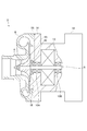
- Drawing 1 is a mimetic diagram showing a rough section composition of electric supercharger 2 concerning one embodiment.
- the electric supercharger 2 includes a compressor impeller 4, a rotating shaft 6, an impeller casing 8, bearings 10 ⁇ / b> A and 10 ⁇ / b> B, a motor 12, a back side casing 14 (stationary member), and a mechanical seal 20. Is provided.
- the axial direction of the compressor impeller 4 is simply referred to as “axial direction”
- the radial direction of the compressor impeller 4 is simply referred to as “radial direction”
- the circumferential direction of the compressor impeller 4 is simply referred to as “circumferential direction”.
- the impeller casing 8 is formed so as to surround the compressor impeller 4, and is configured to guide intake air to the inlet of the compressor impeller 4 and to discharge air compressed by the compressor impeller 4.
- Each of the bearings 10A and 10B is configured as, for example, a rolling bearing so as to rotatably support the rotating shaft 6, and grease is provided as a lubricant around a rolling element held between an inner ring and an outer ring (not shown). It is configured as a sealed grease lubrication type bearing.
- the bearing 10 ⁇ / b> A is positioned between the mechanical seal 20 and the motor 12 in the axial direction, and is positioned between the rear casing 14 and the rotating shaft 6 in the radial direction.
- the bearing 10B is located on the opposite side of the bearing 10A across the motor 12 in the axial direction, and is located between the back casing 14 and the rotary shaft 6 in the radial direction.
- the motor 12 is configured to transmit a driving force to the compressor impeller 4 via the rotary shaft 6.
- the motor 12 is located between the bearing 10A and the bearing 10B in the axial direction.
- the rear casing 14 is configured to face the rear surface 16 of the compressor impeller 4 through a gap and surround the mechanical seal 20, the bearings 10A and 10B, and the motor 12. Further, the back casing 14 includes an inverter accommodating portion 18 for accommodating an inverter (not shown) on the opposite side of the motor 12 with the bearing 10B interposed therebetween.
- the mechanical seal 20 is positioned between the back surface 16 of the compressor impeller 4 and the bearing 10A in the axial direction, and is configured to seal a gap between the rotary shaft 6 and the back side casing 14.
- FIG. 2 is a schematic diagram illustrating a schematic cross-sectional configuration in the vicinity of the back surface 16 of the compressor impeller 4 in the electric supercharger 2 (2A) according to the embodiment, and illustrates a configuration example of the mechanical seal 20.
- FIG. FIG. 3 is a diagram illustrating a state when the compressor impeller 4 rotates in the electric supercharger 2 (2A) illustrated in FIG.
- the mechanical seal 20 includes a stationary ring 22, a rotating ring 24, and a biasing member 26.
- the stationary ring 22 is configured in a ring shape along the circumferential direction and is supported by the rear casing 14.
- the stationary ring 22 is disposed at a position between the rotating ring 24 and the back side casing 14 and between the back side casing 14 and the rotating shaft 6.
- the rotary ring 24 is provided between the back surface 16 of the compressor impeller 4 and the fixed ring 22, and is configured in an annular shape along the circumferential direction so as to face the fixed ring 22 so as to be able to contact in the axial direction. .
- the rotating ring 24 is configured to protrude outward from the rotating shaft 6 in the radial direction, and rotates together with the rotating shaft 6.
- the biasing member 26 is configured to bias one of the fixed ring 22 and the rotating ring 24 toward the other of the fixed ring 22 and the rotating ring 24.
- the urging member 26 is formed of an elastic member (for example, a coil spring, a disc spring, or rubber), and the fixed ring 22 and the rear side are urged to urge the fixed ring 22 toward the rotating ring 24. It is interposed between the casing 14.
- a facing surface 32 that is one of the surface 28 of the rotating ring 24 that faces the fixed ring 22 and the surface 30 of the fixed ring 22 that faces the rotating ring 24 (in the form shown, the fixed ring 22 is included in the rotating ring 24).
- Grooves 34 are formed in the opposing surface 28).
- the groove 34 of the facing surface 32 has a space 36 (a space between the stationary ring 22 and the rotating shaft 6) on the radially inner side of the facing surface 32 when the stationary ring 22 and the rotating ring 24 are in contact with each other.
- the groove 34 is located on the inner side in the radial direction from the inner peripheral end 40 of the contact portion between the fixed ring 22 and the rotary ring 24 on the facing surface 32 in a state where the fixed ring 22 and the rotary ring 24 are in contact with each other. To the position where it does not reach the outer peripheral end 42 of the contact portion between the stationary ring 22 and the rotating ring 24 on the opposing surface 32.
- the stationary ring 22 is pushed toward the biasing member 26 as shown in FIG. 3 by the pressure of the gas in the groove 34 increased by the centrifugal force.
- the stationary ring 22 and the rotating ring 24 are not in contact with each other, but the pressure in the space 38 inside the facing surface 32 becomes higher than the pressure in the space 38 outside the facing surface 32, so Intrusion of the leakage flow into 10A can be suppressed. Therefore, the inflow of the leakage flow into the electric device such as the motor 12 can be suppressed. Therefore, generation
- FIG. 4 is a schematic diagram illustrating a schematic cross-sectional configuration in the vicinity of the rear surface 16 of the compressor impeller 4 in the electric supercharger 2 (2B) according to the embodiment.
- FIG. 5 is a diagram illustrating a configuration example of the ribs 44 illustrated in FIG. 4, and illustrates an example of the arrangement of the ribs 44 when viewed in the axial direction.
- FIG. 6 is a diagram illustrating a configuration example of the ribs 44 illustrated in FIG. 4, and illustrates an example of the arrangement of the ribs 44 when viewed in the axial direction.
- a plurality of ribs 44 are provided on the back surface 16 of the compressor impeller 4 at intervals in the circumferential direction.
- the centrifugal force outward in the radial direction acts on the air in the back gap g when the compressor impeller 4 rotates, thereby reducing the pressure in the inner peripheral portion of the back gap g. be able to.
- invasion of the leak flow from the back surface gap g to 10 A of bearings can be suppressed, and the inflow of this leak flow to electric equipments, such as a motor, can be suppressed.
- each of the ribs 44 extends along a direction intersecting the circumferential direction.
- the plurality of ribs 44 extend radially along a direction (radial direction) orthogonal to the circumferential direction.
- each of the ribs 44 has a wing shape. According to such a configuration, the air flow outward in the radial direction in the rear gap g when the compressor impeller 4 rotates can be effectively formed by the blade-shaped ribs 44. Thereby, the penetration
- the rib 44 is arranged such that the outer peripheral end 46 of the rib 44 is positioned upstream of the inner peripheral end 48 of the rib 44 in the rotational direction of the compressor impeller 4. , Extending in a direction inclined with respect to the radial direction.
- FIG. 7 is a schematic diagram showing a schematic cross-sectional configuration in the vicinity of the back surface 16 of the compressor impeller 4 in the electric supercharger 2 (2C) according to the embodiment.
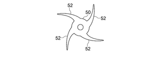
- FIG. 8 is a diagram illustrating a configuration example of the rotating unit 50 illustrated in FIG. 7, and illustrates an example of the shape of the rotating unit 50 when viewed in the axial direction.
- FIG. 9 is a diagram illustrating a configuration example of the rotating unit 50 illustrated in FIG. 7, and illustrates an example of the shape of the rotating unit 50 when viewed in the axial direction.
- FIG. 10 is a diagram illustrating a configuration example of the rotating unit 50 illustrated in FIG. 7, and illustrates an example of the shape of the rotating unit 50 when viewed in the axial direction.
- the rotating part 50 is further provided.
- the shape of the rotation part 50 is not specifically limited, For example, as shown in FIG. 8, an annular shape may be sufficient, and as shown in FIG.9 and FIG. Projections 52 (four projections 52 in the illustrated form).
- the protrusions 52 may protrude radially along the radial direction as shown in FIG. 9, or may have a tapered shape protruding obliquely with respect to the radial direction as shown in FIG.
- FIG. 11 is a schematic diagram showing a schematic cross-sectional configuration in the vicinity of the rear surface 16 of the compressor impeller 4 in the electric supercharger 2 (2D) according to the embodiment.
- FIG. 12 is a diagram showing the relationship between the radial position R and the gauge pressure P of the back gap g, and the broken line shows the electric supercharger 2 (2A) that does not include the abradable coating layer 90. The solid line shows the electric supercharger 2 (2D) in which the abradable coating layer 90 is formed on the facing surface 21.
- FIG. 13 is a schematic diagram illustrating a schematic cross-sectional configuration in the vicinity of the back surface 16 of the compressor impeller 4 in the electric supercharger 2 (2E) according to the embodiment.
- At least a part of the facing surface 21 of the back casing 14 that faces the back surface 16 of the compressor impeller 4 is formed.
- FIG. 12 is a diagram showing a schematic relationship between the radial direction position R and the gauge pressure P of the back surface gap g.
- the broken line indicates the electric supercharger 2 (2A) that does not include the abradable coating layer 90.
- the solid line shows the electric supercharger 2 (2D) in which the abradable coating layer 90 is formed on the facing surface 21.
- the clearance C between the rear surface 16 and the rear casing 14 in the electric supercharger 2 (2D) is set to be smaller than the clearance between the rear surface 16 and the rear casing 14 in the electric supercharger 2 (2A). Yes.
- the electric supercharger 2 by promoting the pressure drop inward in the radial direction in the back gap g, the pressure in the inner peripheral portion of the back gap g (pressure in the vicinity of the mechanical seal 20), The pressure difference in the axial direction from the pressure in the vicinity of the bearing 10A can be reduced, and the leakage flow from the back gap g to the bearing 10A side (the mechanical seal 20 side) can be suppressed. Thereby, the inflow of the leakage flow to electric devices, such as the motor 12 and an inverter (not shown), can be suppressed. Therefore, generation
- the compressor impeller 4 receives a thrust force in the axial direction when compressing air to the upstream side in the air suction direction (left side in the figure).
- the compressor impeller 4 is Since the pressure of the back surface gap g can be reduced, the axial thrust force can be reduced.
- the spring of the biasing member 26 necessary for appropriately moving the stationary ring 22 by promoting the pressure drop inward in the radial direction in the back gap g and lowering the pressure in the inner peripheral portion of the back gap g.
- the force can be reduced, and the progress of wear due to the rubbing between the stationary ring 22 and the rotating ring 24 can be suppressed.
- the ratio C / Ri between the clearance C between the rear surface 16 of the compressor impeller 4 and the rear casing 14 and the outer diameter Ri of the compressor impeller 4 is less than 0.5%.
- the abradable coating layer 90 is formed on at least a part of the back surface 16 of the compressor impeller 4. Further, the ratio C / Ri between the clearance C between the rear surface 16 of the compressor impeller 4 and the rear casing 14 and the outer diameter Ri of the compressor impeller 4 is less than 0.5%.
- the bearing 10A side (mechanical seal) from the back gap g. 20 side) can be prevented from entering the leakage flow.
- the inflow of the leakage flow to electric devices, such as the motor 12 and an inverter (not shown) can be suppressed. Therefore, generation
- the pressure in the rear gap g can be reduced by reducing the clearance C, the axial thrust force in the compressor impeller 4 can be reduced.
- the spring of the biasing member 26 necessary for appropriately moving the stationary ring 22 by promoting the pressure drop inward in the radial direction in the back gap g and lowering the pressure in the inner peripheral portion of the back gap g.
- the force can be reduced, and the progress of wear due to the rubbing between the stationary ring 22 and the rotating ring 24 can be suppressed.
- the pressure inside the back side casing 14 is adjusted by communicating the inside and outside of the back side casing 14.
- a communication hole 53 is further provided as an internal pressure adjusting mechanism configured to do this.
- the communication hole 53 may be provided on the compressor side of the rear casing 14 as shown in FIG. 14, for example, or may be provided on the inverter side as shown in FIG. 15, or may be provided on both sides thereof.
- the position, shape, hole diameter and other dimensions of the communication hole 53 are optimally designed according to the size of the electric supercharger 2.
- the rear side casing 14 is made of dust, water, oil, etc. while adjusting the pressure and temperature inside the rear side casing 14 on the outer end side of the communication hole 53.
- the waterproof ventilation filter 55 which protects the inside is provided.
- the mechanical seal 20 can stably suppress the leakage flow that has passed through the back gap g from entering the bearings 10 ⁇ / b> A and 10 ⁇ / b> B.
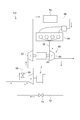
- FIG. 16 is a diagram showing a schematic configuration of the engine apparatus 100 to which the above-described electric supercharger 2 (2A to 2E) can be suitably applied.
- FIG. 16 shows an embodiment of the engine apparatus 100 when the electric supercharger 2 is used as a high-pressure supercharger of a two-stage supercharging system.
- the engine apparatus 100 shown in FIG. 16 includes an engine 54, an intake passage 56 through which intake gas supplied to the engine 54 flows, an exhaust passage 58 through which exhaust gas discharged from the engine 54 flows, a turbocharger 60, and The above-described electric supercharger 2 is provided.
- the turbocharger 60 includes an exhaust turbine 64 disposed in the exhaust passage 58, a compressor 62 disposed in the intake passage 56, and a turbine shaft 63 that connects the exhaust turbine 64 and the compressor 62.
- the turbocharger 60 is configured to supercharge the intake gas flowing through the intake passage 56 when the exhaust turbine 64 is driven by the exhaust gas discharged from the engine 54 and the compressor 62 is coaxially driven via the turbine shaft 63. Has been.
- the electric supercharger 2 is arranged on the downstream side of the compressor 62 in the intake passage 56, and the intake gas compressed by the compressor 62 of the turbocharger 60 is supplied to the compressor impeller 4 of the electric supercharger 2. .
- the engine device 100 of the present embodiment is configured as a two-stage supercharging system in which the turbocharger 60 is disposed as a low pressure supercharger and the electric supercharger 2 is disposed as a high pressure supercharger.
- a bypass intake passage 66 that bypasses the electric supercharger 2 is connected to the intake passage 56.
- a bypass valve 68 is disposed in the bypass intake passage 66. The flow rate of the intake gas flowing into the electric supercharger 2 is controlled by adjusting the valve opening degree of the bypass valve 68.
- an intermediate cooler 70 for cooling the intake gas supplied to the engine 54 is disposed on the downstream side of the electric supercharger 2 in the intake passage 56.
- the engine apparatus 100 is provided with an EGR passage 72 that connects a downstream side of the exhaust turbine 64 in the exhaust passage 58 and an upstream side of the compressor 62 in the intake passage 56.
- An EGR valve 74 is disposed in the EGR passage 72. Then, by adjusting the valve opening of the EGR valve 74, the exhaust gas having a flow rate corresponding to the valve opening returns to the intake passage 56. Then, the intake gas including the recirculated exhaust gas is supplied to the compressor impeller 4 of the electric supercharger 2.
- the bypass valve 68 is closed at the time of engine low speed rotation, and the intake gas boosted by the turbocharger 60 serving as the low pressure stage supercharger is, as indicated by the arrow a, the high pressure stage supercharger. Is supplied to the electric supercharger 2 and further boosted. Therefore, compared with the case where the electric supercharger 2 is arranged in the low pressure stage, the differential pressure between the outer peripheral portion and the inner peripheral portion of the compressor in the electric supercharger 2 is increased, and the above-described rear gap g has a high temperature and high pressure. Intake air enters.
- the bypass valve 68 is opened and the electric supercharger 2 is stopped during high-speed rotation of the engine.
- the intake gas boosted by the turbocharger 60 as a low-pressure supercharger is supplied to the downstream side of the electric supercharger 2 through the bypass intake passage 66 as indicated by an arrow b.
- the boost pressure of the turbocharger 60 generates a differential pressure between the outer peripheral portion and the inner peripheral portion of the compressor in the electric supercharger 2, and the intake air enters the above-described rear gap g.
- the high-temperature and high-pressure intake air can be prevented from entering the bearing side from the back gap g. , 10B, the motor 12 and the like can be effectively prevented from occurring.
- the high-temperature and high-pressure intake air can be prevented from entering the bearing side from the back gap g. , 10B, the motor 12 and the like can be effectively prevented from occurring.
- the present invention is not limited to the above-described embodiments, and includes forms obtained by modifying the above-described embodiments and forms obtained by appropriately combining these forms.
- the back side casing 14 surrounds the mechanical seal 20, the bearings 10A and 10B, and the motor 12, but the configuration of the back side casing 14 is not limited to this. May surround only the mechanical seal 20, and a casing separate from the back side casing 14 may surround the bearings 10A, 10B and the motor 12, or the back side casing 14 may surround only the mechanical seal 20 and the bearing 10A. However, a casing separate from the back side casing 14 may surround the bearing 10 ⁇ / b> B and the motor 12.
- FIG. 17 is a schematic diagram showing a schematic cross-sectional configuration in the vicinity of the rear surface 16 of the compressor impeller 4 in the electric supercharger 2 (2F) according to another invention.
- FIG. 18 is a schematic diagram showing a schematic cross-sectional configuration in the vicinity of the back surface 16 of the compressor impeller 4 in the electric supercharger 2 (2G) according to another invention.
- FIG. 19 is a schematic diagram showing a schematic cross-sectional configuration in the vicinity of the back surface 16 of the compressor impeller 4 in the electric supercharger 2 (2H) according to another invention.
- FIG. 20 is a schematic diagram showing a schematic cross-sectional configuration in the vicinity of the back surface 16 of the compressor impeller 4 in the electric supercharger 2 (2I) according to another invention.
- FIG. 21 is a schematic diagram showing a schematic cross-sectional configuration in the vicinity of the back surface 16 of the compressor impeller 4 in the electric supercharger 2 (2J) according to another invention.
- FIG. 22 is a schematic diagram showing a schematic cross-sectional configuration in the vicinity of the rear surface 16 of the compressor impeller 4 in the electric supercharger 2 (2K) according to another invention.
- the basic configuration of the electric supercharger 2 (2F to 2K) is the same as the basic configuration of the electric supercharger 2 shown in FIG. 1 except that the mechanical seal 20 is not provided. The description will be omitted, and the characteristic configuration of each embodiment will be mainly described.
- the electric supercharger 2 (2F to 2H) is directed radially outward from the rotary shaft 6 between the back surface 16 and the back side casing 14 of the compressor impeller 4. And a rotating portion 76 configured to rotate together with the rotating shaft 6. Further, the outer peripheral end 78 of the rotating portion 76 is located on the radially outer side than the inner peripheral end 80 of the back side casing 14.
- the shape of the rotating part 76 is not particularly limited, but each shape of the rotating part 50 described with reference to FIGS. 8 to 10 can be adopted.
- the rotation part 76 may be arrange
- the rotating portion 76 has a convex portion 84 protruding in the axial direction so as to enter the inside of the concave portion 82 as shown in FIG. You may have.
- the electric supercharger 2 (2I) is obtained by replacing the mechanical seal 20 in the electric supercharger 2 (2B) shown in FIG.
- the electric supercharger 2 (2I) like the electric supercharger 2 (2B), a plurality of ribs 44 are provided on the back surface 16 of the compressor impeller 4 at intervals in the circumferential direction.
- the seal unit 9 includes a sleeve 86 and at least one piston ring 88 (two piston rings 88 in the illustrated form).
- the sleeve 86 is provided so that one end side thereof is in contact with the back surface 16 of the compressor impeller 4 in a state of being fitted to the rotary shaft 6.
- the piston ring 88 is fitted into an annular groove provided on the outer peripheral surface of the sleeve 86 and is in contact with the rear casing 14 to seal a gap between the rotary shaft 6 and the rear casing 14.
- the electric supercharger 2 (2J) is obtained by replacing the mechanical seal 20 in the electric supercharger 2 (2D) shown in FIG.
- the electric supercharger 2 (2J) as in the electric supercharger 2 (2D), at least a part of the opposed surface 21 that faces the back surface 16 of the compressor impeller 4 in the rear casing 14 (opposed in the illustrated form).
- the abradable coating layer 90 is formed on the entire surface 21).
- the compressor impeller 4 receives a thrust force in the axial direction in the air suction direction (left side in the figure) when compressing air.
- the electric supercharger 2 (2J) Since the impeller 4 can reduce the pressure of the back surface gap g, the axial thrust force can be reduced.
- the electric supercharger 2 (2K) is obtained by replacing the mechanical seal 20 in the electric supercharger 2 (2E) shown in FIG.
- the abradable coating layer 90 is formed on at least a part of the back surface 16 of the compressor impeller 4 as in the electric supercharger 2 (2E).
- the compressor impeller 4 receives a thrust force in the axial direction toward the upstream side (left side in the drawing) of the air when compressing the air.
- the electric supercharger 2 (2K) Since the impeller 4 can reduce the pressure of the back surface gap g, the axial thrust force can be reduced.
- the electric supercharger 2 (2A to 2E) can be suitably used as the high-pressure supercharger of the two-stage supercharging system, but as shown in FIG.
- the electric supercharger 2 (2A to 2K) may be used as the low pressure supercharger of the two-stage supercharging system.
- the electric supercharger 2 is disposed on the upstream side of the compressor 62 in the intake passage 56, and the intake gas compressed by the electric supercharger 2 is compressed by the compressor 62 of the turbocharger 60. Supplied to.
- the engine device 110 is configured as a two-stage supercharging system in which the turbocharger 60 is disposed as a high pressure supercharger and the electric supercharger 2 is disposed as a low pressure supercharger.
- a bypass intake passage 66 that bypasses the electric supercharger 2 is connected to the intake passage 56.
- a bypass valve 68 is disposed in the bypass intake passage 66. The flow rate of the intake gas flowing into the electric supercharger 2 is controlled by adjusting the valve opening degree of the bypass valve 68.
- an intermediate cooler 70 for cooling the intake gas supplied to the engine 54 is disposed on the downstream side of the compressor 62 in the intake passage 56.
- the engine device 110 is provided with an EGR passage 72 that connects a downstream side of the exhaust turbine 64 in the exhaust passage 58 and an upstream side of the electric supercharger 2 in the intake passage 56.
- An EGR valve 74 is disposed in the EGR passage 72. Then, by adjusting the valve opening of the EGR valve 74, the exhaust gas having a flow rate corresponding to the valve opening returns to the intake passage 56. Then, the intake gas including the recirculated exhaust gas is supplied to the compressor impeller 4 of the electric supercharger 2.
- the bypass valve 68 is closed at the time of engine low-speed rotation, and the intake gas boosted by the electric supercharger 2 as the low-pressure stage supercharger is high-pressure stage excess as shown by an arrow c.
- the pressure is supplied to a compressor 62 of a turbocharger 60 as a feeder and further boosted. Therefore, the boost pressure of the electric supercharger 2 is applied between the outer peripheral portion and the inner peripheral portion of the compressor in the electric supercharger 2, and the intake air enters the back gap g described above.
- the bypass valve 68 is opened and the electric supercharger 2 is stopped at the time of high-speed engine rotation.
- the intake gas is supplied to the compressor 62 through the bypass intake passage 66 as shown by the arrow d, the intake air hardly enters the rear gap g of the electric supercharger 2.
Abstract
L'invention concerne un surcompresseur entraîné électriquement comprenant : une roue de compresseur ; un moteur conçu pour transmettre une force d'entraînement à la roue de compresseur par l'intermédiaire d'un arbre rotatif ; un boîtier arrière faisant face à la surface arrière de la roue de compresseur avec un espace entre eux et entourant l'arbre rotatif ; un palier disposé entre le boîtier arrière et l'arbre rotatif de façon à supporter en rotation l'arbre rotatif ; et un joint mécanique situé entre la surface arrière de la roue de compresseur et le palier dans la direction axiale de la roue de compresseur et conçu pour sceller l'espace entre l'arbre rotatif et le boîtier arrière.
Priority Applications (5)
| Application Number | Priority Date | Filing Date | Title |
|---|---|---|---|
| EP17904301.3A EP3489484B1 (fr) | 2017-03-29 | 2017-03-29 | Surcompresseur entraîné électriquement |
| JP2019508432A JP6618651B2 (ja) | 2017-03-29 | 2017-03-29 | 電動過給機 |
| US16/326,640 US20200378389A1 (en) | 2017-03-29 | 2017-03-29 | Electric supercharger |
| PCT/JP2017/012938 WO2018179144A1 (fr) | 2017-03-29 | 2017-03-29 | Surcompresseur entraîné électriquement |
| CN201780050342.6A CN109563772B (zh) | 2017-03-29 | 2017-03-29 | 电动增压器 |
Applications Claiming Priority (1)
| Application Number | Priority Date | Filing Date | Title |
|---|---|---|---|
| PCT/JP2017/012938 WO2018179144A1 (fr) | 2017-03-29 | 2017-03-29 | Surcompresseur entraîné électriquement |
Publications (1)
| Publication Number | Publication Date |
|---|---|
| WO2018179144A1 true WO2018179144A1 (fr) | 2018-10-04 |
Family
ID=63674622
Family Applications (1)
| Application Number | Title | Priority Date | Filing Date |
|---|---|---|---|
| PCT/JP2017/012938 WO2018179144A1 (fr) | 2017-03-29 | 2017-03-29 | Surcompresseur entraîné électriquement |
Country Status (5)
| Country | Link |
|---|---|
| US (1) | US20200378389A1 (fr) |
| EP (1) | EP3489484B1 (fr) |
| JP (1) | JP6618651B2 (fr) |
| CN (1) | CN109563772B (fr) |
| WO (1) | WO2018179144A1 (fr) |
Families Citing this family (3)
| Publication number | Priority date | Publication date | Assignee | Title |
|---|---|---|---|---|
| US11598347B2 (en) * | 2019-06-28 | 2023-03-07 | Trane International Inc. | Impeller with external blades |
| EP4050217A1 (fr) * | 2021-02-26 | 2022-08-31 | BMTS Technology GmbH & Co. KG | Compresseur de gaz |
| DE102021212662A1 (de) * | 2021-11-10 | 2023-05-11 | Robert Bosch Gesellschaft mit beschränkter Haftung | Radialverdichter und Verfahren zum Betreiben eines Radialverdichters |
Citations (12)
| Publication number | Priority date | Publication date | Assignee | Title |
|---|---|---|---|---|
| JPS58106521U (ja) * | 1982-01-12 | 1983-07-20 | 日産自動車株式会社 | タ−ボ過給機の軸封装置 |
| JPS60107332U (ja) * | 1983-12-21 | 1985-07-22 | 日産自動車株式会社 | 排気タ−ビン過給機 |
| JPS62183036U (fr) * | 1986-05-13 | 1987-11-20 | ||
| JPH11173153A (ja) * | 1997-12-10 | 1999-06-29 | Kyoritsu:Kk | 滑り部材付きターボチャージャ |
| JP2005163643A (ja) * | 2003-12-03 | 2005-06-23 | Koyo Seiko Co Ltd | 電動駆動式過給機 |
| JP2005226470A (ja) * | 2004-02-10 | 2005-08-25 | Kyoritsu:Kk | ターボチャージャ |
| JP2007309101A (ja) * | 2006-05-16 | 2007-11-29 | Toyota Motor Corp | 電動機付き過給機の冷却構造 |
| JP2011021545A (ja) * | 2009-07-16 | 2011-02-03 | Ihi Corp | ターボチャージャのコンプレッサ構造 |
| JP2011052558A (ja) * | 2009-08-31 | 2011-03-17 | Toyota Motor Corp | 過給機 |
| JP2013024059A (ja) * | 2011-07-15 | 2013-02-04 | Mitsubishi Heavy Ind Ltd | 電動過給圧縮機、その組立方法及び内燃機関 |
| JP2013024041A (ja) * | 2011-07-15 | 2013-02-04 | Mitsubishi Heavy Ind Ltd | 電動過給装置及び多段過給システム |
| WO2016152139A1 (fr) * | 2015-03-23 | 2016-09-29 | 株式会社デンソー | Dispositif de suralimentation |
Family Cites Families (7)
| Publication number | Priority date | Publication date | Assignee | Title |
|---|---|---|---|---|
| GB452019A (en) * | 1935-02-14 | 1936-08-14 | Watkins & Watson Ltd | Improvements in and connected with centrifugal pumps, fans and blowers |
| US2679412A (en) * | 1950-03-24 | 1954-05-25 | Read Standard Corp | Seal |
| US4820115A (en) * | 1987-11-12 | 1989-04-11 | Dresser Industries, Inc. | Open impeller for centrifugal compressors |
| FR2827919B1 (fr) * | 2001-07-26 | 2004-03-05 | Thermodyn | Garniture d'etancheite pour compresseur et compresseur centrifuge pourvu d'une telle garniture |
| KR101429846B1 (ko) * | 2013-02-06 | 2014-08-12 | 한승주 | 자기 구동 공기충전장치 |
| DE102015106640A1 (de) * | 2014-07-02 | 2016-01-07 | Pierburg Gmbh | Elektrischer Verdichter für eine Verbrennungskraftmaschine |
| CN209875297U (zh) * | 2019-04-01 | 2019-12-31 | 中国科学院合肥物质科学研究院 | 一种新型一体式电子涡轮增压器 |
-
2017
- 2017-03-29 WO PCT/JP2017/012938 patent/WO2018179144A1/fr unknown
- 2017-03-29 EP EP17904301.3A patent/EP3489484B1/fr active Active
- 2017-03-29 CN CN201780050342.6A patent/CN109563772B/zh active Active
- 2017-03-29 US US16/326,640 patent/US20200378389A1/en not_active Abandoned
- 2017-03-29 JP JP2019508432A patent/JP6618651B2/ja active Active
Patent Citations (12)
| Publication number | Priority date | Publication date | Assignee | Title |
|---|---|---|---|---|
| JPS58106521U (ja) * | 1982-01-12 | 1983-07-20 | 日産自動車株式会社 | タ−ボ過給機の軸封装置 |
| JPS60107332U (ja) * | 1983-12-21 | 1985-07-22 | 日産自動車株式会社 | 排気タ−ビン過給機 |
| JPS62183036U (fr) * | 1986-05-13 | 1987-11-20 | ||
| JPH11173153A (ja) * | 1997-12-10 | 1999-06-29 | Kyoritsu:Kk | 滑り部材付きターボチャージャ |
| JP2005163643A (ja) * | 2003-12-03 | 2005-06-23 | Koyo Seiko Co Ltd | 電動駆動式過給機 |
| JP2005226470A (ja) * | 2004-02-10 | 2005-08-25 | Kyoritsu:Kk | ターボチャージャ |
| JP2007309101A (ja) * | 2006-05-16 | 2007-11-29 | Toyota Motor Corp | 電動機付き過給機の冷却構造 |
| JP2011021545A (ja) * | 2009-07-16 | 2011-02-03 | Ihi Corp | ターボチャージャのコンプレッサ構造 |
| JP2011052558A (ja) * | 2009-08-31 | 2011-03-17 | Toyota Motor Corp | 過給機 |
| JP2013024059A (ja) * | 2011-07-15 | 2013-02-04 | Mitsubishi Heavy Ind Ltd | 電動過給圧縮機、その組立方法及び内燃機関 |
| JP2013024041A (ja) * | 2011-07-15 | 2013-02-04 | Mitsubishi Heavy Ind Ltd | 電動過給装置及び多段過給システム |
| WO2016152139A1 (fr) * | 2015-03-23 | 2016-09-29 | 株式会社デンソー | Dispositif de suralimentation |
Non-Patent Citations (1)
| Title |
|---|
| See also references of EP3489484A4 * |
Also Published As
| Publication number | Publication date |
|---|---|
| EP3489484A4 (fr) | 2020-01-15 |
| JP6618651B2 (ja) | 2019-12-11 |
| JPWO2018179144A1 (ja) | 2019-07-18 |
| US20200378389A1 (en) | 2020-12-03 |
| EP3489484A1 (fr) | 2019-05-29 |
| CN109563772B (zh) | 2021-01-26 |
| EP3489484B1 (fr) | 2021-05-05 |
| CN109563772A (zh) | 2019-04-02 |
Similar Documents
| Publication | Publication Date | Title |
|---|---|---|
| US9382812B2 (en) | Anisotropic bearing supports for turbochargers | |
| US7670056B2 (en) | Stepped outer diameter semi-floating bearing | |
| US9963998B2 (en) | Assembly with bearings and spacer | |
| CA2352021C (fr) | Dispositif d'etancheite a double phase pour arbre de turbocompresseur | |
| US6406253B2 (en) | Turbocharger | |
| US9874217B2 (en) | Turbomachine shaft sealing arrangement | |
| KR20040014244A (ko) | 터보차저 | |
| US9695708B2 (en) | Turbocharger spring assembly | |
| JP6618651B2 (ja) | 電動過給機 | |
| WO2015128935A1 (fr) | Structure d'étanchéité et compresseur de suralimentation pourvu de ladite structure d'étanchéité | |
| JP2016525183A (ja) | 線対称の供給キャビティを備えたターボ過給機パージシール | |
| WO2015114971A1 (fr) | Unité buse variable et compresseur à suralimentation à cylindrée variable | |
| US20140334918A1 (en) | Variable nozzle unit and variable geometry system turbocharger | |
| KR20170131492A (ko) | 오일 가이드를 구비한 오일 디플렉터 | |
| JP2013253521A (ja) | 可変ノズルユニット及び可変容量型過給機 | |
| JP2018145910A (ja) | 電動過給機 | |
| CN107683374B (zh) | 密封结构以及增压器 | |
| KR101532439B1 (ko) | 배기 가스 터보 과급기용 스러스트 베어링 시일 | |
| JP2012057507A (ja) | シール構造及び過給機 | |
| EP3698060A1 (fr) | Système de palier turbo | |
| CN110959073B (zh) | 涡轮机,尤其用于燃料电池系统 | |
| US10598043B2 (en) | Turbocharger | |
| EP3698059A1 (fr) | Palier de turbocompresseur monobloc |
Legal Events
| Date | Code | Title | Description |
|---|---|---|---|
| 121 | Ep: the epo has been informed by wipo that ep was designated in this application |
Ref document number: 17904301 Country of ref document: EP Kind code of ref document: A1 |
|
| ENP | Entry into the national phase |
Ref document number: 2019508432 Country of ref document: JP Kind code of ref document: A |
|
| ENP | Entry into the national phase |
Ref document number: 2017904301 Country of ref document: EP Effective date: 20190219 |
|
| NENP | Non-entry into the national phase |
Ref country code: DE |