WO2018176630A1 - 一种连接器、电子器件及电子设备 - Google Patents
一种连接器、电子器件及电子设备 Download PDFInfo
- Publication number
- WO2018176630A1 WO2018176630A1 PCT/CN2017/086720 CN2017086720W WO2018176630A1 WO 2018176630 A1 WO2018176630 A1 WO 2018176630A1 CN 2017086720 W CN2017086720 W CN 2017086720W WO 2018176630 A1 WO2018176630 A1 WO 2018176630A1
- Authority
- WO
- WIPO (PCT)
- Prior art keywords
- electronic device
- probe
- magnet
- hole
- fixing frame
- Prior art date
Links
Images


Classifications
-
- H—ELECTRICITY
- H01—ELECTRIC ELEMENTS
- H01R—ELECTRICALLY-CONDUCTIVE CONNECTIONS; STRUCTURAL ASSOCIATIONS OF A PLURALITY OF MUTUALLY-INSULATED ELECTRICAL CONNECTING ELEMENTS; COUPLING DEVICES; CURRENT COLLECTORS
- H01R13/00—Details of coupling devices of the kinds covered by groups H01R12/70 or H01R24/00 - H01R33/00
- H01R13/62—Means for facilitating engagement or disengagement of coupling parts or for holding them in engagement
- H01R13/629—Additional means for facilitating engagement or disengagement of coupling parts, e.g. aligning or guiding means, levers, gas pressure electrical locking indicators, manufacturing tolerances
-
- G—PHYSICS
- G06—COMPUTING; CALCULATING OR COUNTING
- G06F—ELECTRIC DIGITAL DATA PROCESSING
- G06F1/00—Details not covered by groups G06F3/00 - G06F13/00 and G06F21/00
- G06F1/16—Constructional details or arrangements
- G06F1/1613—Constructional details or arrangements for portable computers
- G06F1/1633—Constructional details or arrangements of portable computers not specific to the type of enclosures covered by groups G06F1/1615 - G06F1/1626
- G06F1/1662—Details related to the integrated keyboard
-
- H—ELECTRICITY
- H01—ELECTRIC ELEMENTS
- H01R—ELECTRICALLY-CONDUCTIVE CONNECTIONS; STRUCTURAL ASSOCIATIONS OF A PLURALITY OF MUTUALLY-INSULATED ELECTRICAL CONNECTING ELEMENTS; COUPLING DEVICES; CURRENT COLLECTORS
- H01R13/00—Details of coupling devices of the kinds covered by groups H01R12/70 or H01R24/00 - H01R33/00
- H01R13/02—Contact members
- H01R13/22—Contacts for co-operating by abutting
- H01R13/24—Contacts for co-operating by abutting resilient; resiliently-mounted
-
- H—ELECTRICITY
- H01—ELECTRIC ELEMENTS
- H01R—ELECTRICALLY-CONDUCTIVE CONNECTIONS; STRUCTURAL ASSOCIATIONS OF A PLURALITY OF MUTUALLY-INSULATED ELECTRICAL CONNECTING ELEMENTS; COUPLING DEVICES; CURRENT COLLECTORS
- H01R13/00—Details of coupling devices of the kinds covered by groups H01R12/70 or H01R24/00 - H01R33/00
- H01R13/62—Means for facilitating engagement or disengagement of coupling parts or for holding them in engagement
- H01R13/6205—Two-part coupling devices held in engagement by a magnet
-
- H—ELECTRICITY
- H01—ELECTRIC ELEMENTS
- H01R—ELECTRICALLY-CONDUCTIVE CONNECTIONS; STRUCTURAL ASSOCIATIONS OF A PLURALITY OF MUTUALLY-INSULATED ELECTRICAL CONNECTING ELEMENTS; COUPLING DEVICES; CURRENT COLLECTORS
- H01R13/00—Details of coupling devices of the kinds covered by groups H01R12/70 or H01R24/00 - H01R33/00
- H01R13/62—Means for facilitating engagement or disengagement of coupling parts or for holding them in engagement
- H01R13/629—Additional means for facilitating engagement or disengagement of coupling parts, e.g. aligning or guiding means, levers, gas pressure electrical locking indicators, manufacturing tolerances
- H01R13/633—Additional means for facilitating engagement or disengagement of coupling parts, e.g. aligning or guiding means, levers, gas pressure electrical locking indicators, manufacturing tolerances for disengagement only
- H01R13/635—Additional means for facilitating engagement or disengagement of coupling parts, e.g. aligning or guiding means, levers, gas pressure electrical locking indicators, manufacturing tolerances for disengagement only by mechanical pressure, e.g. spring force
-
- H—ELECTRICITY
- H01—ELECTRIC ELEMENTS
- H01R—ELECTRICALLY-CONDUCTIVE CONNECTIONS; STRUCTURAL ASSOCIATIONS OF A PLURALITY OF MUTUALLY-INSULATED ELECTRICAL CONNECTING ELEMENTS; COUPLING DEVICES; CURRENT COLLECTORS
- H01R13/00—Details of coupling devices of the kinds covered by groups H01R12/70 or H01R24/00 - H01R33/00
- H01R13/62—Means for facilitating engagement or disengagement of coupling parts or for holding them in engagement
- H01R13/639—Additional means for holding or locking coupling parts together, after engagement, e.g. separate keylock, retainer strap
Definitions
- the present application relates to the field of electronic product technologies, and in particular, to a connector, an electronic device, and an electronic device.
- a keyboard for connecting to a tablet computer is designed.
- a product that can be combined or detached between a tablet and a keyboard is called a two-in-one computer.
- the tablet and keyboard can be connected through a physical connector or Bluetooth.
- FIG. 1 is a keyboard 01 for a two-in-one computer with a physical connector provided by the prior art.
- the physical connector is placed at the rear edge of the keyboard 01.
- the physical connector includes a probe assembly 011 that is fixed to the upper surface of the keyboard 01, the probe protrudes from the upper surface of the keyboard 01, and the probe assembly 011 includes a plurality of probes (ie, Pogo pins) arranged in a straight line.
- a positioning post 012 is disposed on each side of the probe assembly 011, and the positioning post 012 is used to position the keyboard 1 and the tablet.
- the keyboard 01 and the tablet are provided with magnets (not shown) at the joints.
- the tablet computer When the tablet computer is close to the keyboard 1, the positioning position of the tablet computer and the probe component 011 of the keyboard 01 are first positioned by the positioning post 012, and the tablet computer is further brought closer to the keyboard 01 after alignment, and the keyboard 01 and the tablet are moved by the adsorption force of the magnet.
- Computer mechanical connection When the tablet is mechanically connected to the keyboard 01, the contacts of the tablet are in contact with the probe of the keyboard 01, thereby realizing the electrical connection between the keyboard 01 and the tablet.
- the probe assembly 011 protrudes from the upper surface of the keyboard 01, the probe is easily damaged during storage and transportation, thereby causing the keyboard to be incapable of being electrically connected to the tablet, and the keyboard is ineffective.
- the embodiments of the present application provide a connector, an electronic device, and an electronic device, which can solve the problem that the probe protrudes from the surface of the keyboard easily damaged in the prior art.
- the present application provides a connector for connecting a first electronic device and a second electronic device, including: a housing having a through hole; and a probe assembly disposed in the housing
- the probe assembly is movable relative to the housing, the probe assembly includes a mounting bracket, and the mounting bracket is provided with a probe; the flexible circuit board has one end connected to the probe, and the other end of the flexible circuit board is used for the first a circuit board connection in the electronic device; a plug structure, the plug structure is detachably inserted into the second electronic device; and the driving component can drive the probe when the second electronic device is plugged into the plug structure
- the assembly moves relative to the housing in a direction toward the through hole such that the probe extends out of the through hole and is coupled to the second electronic device.
- the probe assembly since the probe assembly is movable relative to the housing, the probe assembly is disposed in the housing during storage and transportation, and the housing can protect the probe assembly, so that the probe assembly is not easily damaged;
- the connector is applied to a two-in-one tablet computer, if the second electronic device is a tablet computer, the first electronic device is a keyboard.
- the driving component drives the probe assembly toward the through hole. The movement allows the probe to extend through the through hole and connect to the tablet, thereby connecting the tablet to the keyboard.
- the driving component comprises a first magnet fixed to the fixing frame, the first magnet is used for mating connection with the second magnet in the second electronic device, and the through hole is opened on the upper cover of the housing, and the second
- the attraction between the first magnet and the second magnet can drive the first magnet and the probe assembly to move toward the through hole, and the magnet is connected and connected, and the structure is simple and connected. More reliable.
- a magnetic adsorption member is disposed on the lower cover of the housing corresponding to the first magnet, and the attraction between the first magnet and the second magnet is greater when the second electronic device is inserted into the plug structure.
- an elastic member is disposed between the probe assembly and the housing, and a force that moves toward the lower cover plate is applied to the probe assembly through the elastic member.
- the elastic member is The probe assembly can be retracted into the housing, and the elastic member fixedly connects the probe assembly to the housing, so that the alignment of the probe and the through hole is relatively accurate.
- the elastic member is a spring, one end of the spring is connected to the upper cover of the casing, and the other end is connected to the fixed frame.
- the spring is in a compressed state, and the spring is directed to the probe assembly. Applying a force to move toward the lower cover plate, when the second electronic device is disengaged from the plug structure, the first magnet and the second magnet are also disengaged, and the restoring force of the spring pushes the probe assembly back into the housing, and the structure It's simpler.
- the elastic member is a spring, one end of the spring is connected to the lower cover of the housing, and the other end is connected to the fixed frame.
- the spring is in a stretched state, and the spring is directed to the probe.
- the component applies a force to move toward the lower cover plate.
- the second electronic device is disengaged from the plug structure, the first magnet and the second magnet are also disengaged, and the restoring force of the spring pulls the probe assembly back into the housing.
- the structure is simpler.
- the driving component includes a motor connected to the fixed frame and a Hall switch connected to the motor, and the second electronic device is provided with a second magnet, and when the second magnet enters the sensing range of the Hall switch When inside, the Hall switch sends a start signal to the motor, causing the motor to move the probe assembly toward the through hole.
- the probe assembly is sensitive and the probe can quickly extend.
- a linear guiding structure is disposed in the housing, and the linear guiding structure is configured to guide the fixing frame to move in a direction perpendicular to the upper cover plate, and the linear guiding structure limits the movement track of the fixing frame, so that the probe can accurately pass through the through hole .
- the linear guiding structure comprises a guiding frame fixed on the lower surface of the upper cover, the side wall of the guiding frame extends in a direction perpendicular to the upper cover, the fixing frame is cooperatively disposed in the guiding frame, and the fixing frame is fixed to the fixing frame
- the movement direction is limited, the structure is simple, and the installation is convenient.
- the fixing frame and the housing are hinged by the rotating shaft, and the driving component can drive the fixing frame to rotate in a direction close to the through hole and can drive the fixing frame to rotate away from the through hole, and the rotation mode is convenient, and the limiting device is not needed. Simple structure.
- the plug structure includes a positioning post disposed on the fixing frame, the positioning post is parallel to the probe, and the length of the positioning post is greater than the length of the probe, and the connection between the first electronic device and the second electronic device is determined by the positioning post The position makes the positioning of the two accurate.
- the plug structure includes a positioning groove disposed on the upper cover, the probe is disposed in the positioning groove, the positioning groove is configured to cooperate with the lower end of the second electronic device, and the second is restricted by the positioning groove
- the mounting position of the electronic device on the first electronic device eliminates the positioning post, making the shape of the first electronic device more beautiful.
- the second magnet is an electromagnet
- the second electronic device is provided with a Hall switch.
- the Hall switch sends a signal to the control circuit of the electromagnet to make the electromagnetic
- the control circuit of the iron is energized, and the first magnet and the second magnet are easier to remove when they are disengaged.
- the present application provides an electronic device comprising the connector of any of the above aspects.
- the present application provides an electronic device including a first electronic device and a second electronic device.
- the first electronic device and the second electronic device are connected by a connector according to any one of the above technical solutions, the first electronic device and The second electronic device connection is more reliable.
- the first electronic device comprises a connector according to any of the above aspects.
- the first electronic device is a keyboard
- the second electronic device is a tablet computer
- the first electronic device is a tablet computer
- the second electronic device is a keyboard
- FIG. 1 is a schematic structural view of a keyboard of a prior art two-in-one computer
- FIG. 2 is a structural split view of a connector according to an embodiment of the present application.
- FIG. 3 is a partial schematic view showing a probe protruding through a through hole in a connector according to an embodiment of the present application
- FIG. 4 is a partial schematic view showing a probe connecting a keyboard and a tablet in a two-in-one computer according to an embodiment of the present application;
- FIG. 5 is a structural split view of a probe assembly in a connector according to an embodiment of the present application.
- FIG. 6 is a partial schematic view showing the connection of a connector keyboard and a tablet computer in a two-in-one computer according to an embodiment of the present application;
- Figure 7 is a partial enlarged view of Figure 6;
- FIG. 8 is a structural exploded view of a probe assembly in another connector of the embodiment of the present application.
- FIG. 9 is a structural split view of the movement of the probe assembly in the connector according to the embodiment of the present application.
- FIG. 10 is a schematic view showing the assembly of the probe assembly in the connector as a rotation according to an embodiment of the present application.
- FIG. 11 is a schematic structural view of a probe in a connector according to an embodiment of the present application.
- FIG. 12 is a schematic structural diagram of a plug-in structure in a connector as a positioning groove according to an embodiment of the present application.
- connection In the description of the present application, it should be noted that the terms “installation”, “connected”, and “connected” are to be understood broadly, and may be fixed or detachable, for example, unless otherwise specifically defined and defined. Connect, It may also be a contraceptive connection or an integral connection; the specific meaning of the above terms in the present application may be understood by a person of ordinary skill in the art.
- An electronic device includes a first electronic device and a second electronic device, the first electronic device or the second electronic device including a connector through which the first electronic device and the second electronic device can be connected Together, the two electronic devices are used as an electronic device, such as a two-in-one computer, the first electronic device can be a keyboard, and the second electronic device can be a tablet computer.
- the above-mentioned designation of the keyboard and the tablet is only a simple example. Actually, it can be assumed that the first electronic device is a tablet computer, the second electronic device is a keyboard, the connection mode and the first electronic device are a keyboard, and the second The assumption that the electronic device is a tablet is the same and will not be described here.
- the electronic device is a two-in-one computer, the first electronic device is a keyboard, and the second electronic device is a tablet computer, and the connector includes the above connector as an example.
- 2 is a schematic structural view of a connector according to an embodiment of the present application
- FIG. 3 is a partial schematic view showing a probe protruding through a through hole in a connector according to an embodiment of the present application
- FIG. 4 is a cross-sectional view of an embodiment of the present application.
- FIG. 5 is a structural split view of a probe assembly in a connector according to an embodiment of the present application.
- the connector comprises a housing 1 and a flexible circuit board 3, and the housing 1 is provided with a through hole 111.
- the housing 1 is provided with a probe assembly 2, and the probe assembly 2 is movable relative to the housing 1.
- the probe assembly 2 includes a fixing frame 21 on which the probe 22 is disposed, the probe 22 is connected to one end of the flexible circuit board 3, and the other end of the flexible circuit board 3 is used for the circuit board in the keyboard 100 ( Connections are not shown in the figure.
- the connector also includes a plug structure 4 and a drive assembly 5.
- the plug structure 4 is detachably inserted into the tablet computer 200. When the tablet computer 200 is inserted into the plug structure 4, the driving component 5 can drive the probe assembly 2 toward the through hole 111 with respect to the housing 1. The movement causes the probe 22 to extend out of the through hole 111 to be connected to the tablet computer 200, thereby integrating the keyboard 100 and the tablet computer 200.
- the probe assembly 2 since the probe assembly 2 is movable relative to the housing 1, the probe assembly 2 is disposed in the housing 1 during storage and transportation, and the housing 1 can protect the probe assembly 2
- the needle assembly 2 is not easily damaged; the flexible circuit board in the connector is connected to the circuit board in the keyboard, and when the tablet computer 200 is inserted into the plug structure 4, the driving assembly 5 drives the probe assembly 2 toward the housing 1
- the direction of movement of the through hole 111 causes the probe 22 to extend through the through hole 111 to be connected to the tablet computer 200, thereby realizing the connection of the tablet computer 200 to the keyboard 100.
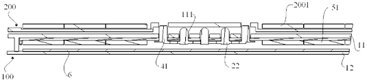
- FIG. 6 is a partial schematic view showing the connection of a connector keyboard and a tablet computer in a two-in-one computer according to an embodiment of the present invention
- FIG. 7 is a partial enlarged view of FIG. 6.
- the structure of the drive assembly 5 in the above embodiment may be various.
- the drive assembly 5 includes a first magnet 51 fixed to the fixed frame 21, and the first magnet 51 is used for the second magnet 2001 in the tablet 200.
- the through hole 111 is opened on the upper cover 11 of the housing 1, as shown in FIGS. 2 and 6-7.
- the first magnet 51 and the second magnet 2001 are attracted to move the first magnet 51 and the probe assembly 2 toward the through hole 111, and magnetically attracted.
- the driving method does not require a transmission structure, the structure is simple, and the connection is reliable.
- the moving form of the probe assembly 2 may be a linear movement or a rotation mode; the connection manner of the first magnet 51 and the fixing frame 21 may be a bonding manner, or a special magnet holder may be used.
- the first magnet 51 is fixed to the magnet holder, the magnet holder and the fixing
- the frame 21 is fixedly connected.
- the probe assembly 2 includes a plurality of probes 22, and the plurality of probes 22 are fixed on the support board 23, and the probes 22 are connected to the flexible circuit board 3 (ie, FPC, Flexible Printed Circuit).
- a plurality of connecting holes 211 are defined in the position of the corresponding probe 22 on the fixing frame 21.
- the probes 22 are disposed correspondingly through the connecting holes 211, and the supporting plate 23 is bonded to the fixing frame 21 or fixed by bolts.
- the first magnet 51 and the second magnet 2001 are disengaged, and the probe assembly 2 and the first magnet 51 can fall together into the housing 1 under the action of gravity, and the structure of the connector is relatively simple.
- a magnetic adsorbing member 6 is disposed on the lower cover 12 of the casing 1 in the embodiment of the present application.
- the tablet computer 200 When the tablet computer 200 is inserted into the plug structure 4, the first magnet 51 and the second magnet The attraction force between the magnets 2001 is greater than the adsorption force between the first magnets 51 and the magnetic adsorbing members 6, whereby the adsorption force between the first magnets 51 and the second magnets 2001 causes the probes 22 to protrude through the through holes 111 and the flat plates.
- the computer 200 is connected as shown in Figures 2 and 5-7.
- the second magnet 2001 is separated from the magnetic force range of the first magnet 51, and the first magnet 51 is attracted to the magnetic adsorbing member 6 on the lower cover 12 of the casing 1, thereby Under the combined action of magnetic force and gravity, the probe assembly 2 is accelerated to fall into the housing 1, and the probe assembly 2 is fixed relative to the lower cover 12 of the housing 1 to prevent the probe from being moved when the user moves or flips the keyboard. 22 through the through hole 111, or the probe assembly 2 is shaken in the housing 1 to generate an abnormal sound; and when transported or subjected to an impact, the probe assembly 2 can be prevented from shaking in the housing 1, causing the probe assembly 2 A problem of misalignment occurs between the through hole 111 of the housing 1.
- the magnetic adsorbing member 6 described above may be a magnet that is magnetically different from the first magnet 51, and may be made of a ferrous material.
- the magnetic adsorbing member 6 may be replaced by providing an elastic member between the probe assembly 2 and the housing 1.
- the probe assembly 2 is biased by the elastic member in a direction toward the lower cover 12 of the housing 1, and the elastic member can push the probe assembly 2 back into the housing 1, and the probe assembly 2 is fixedly connected to the housing 1.
- the position of the probe assembly 2 is limited, thereby avoiding the problem of misalignment between the probe assembly 2 and the through hole 111 of the housing 1, and the noise during the operation is small.
- the elastic member may be a spring, one end of the spring is connected to the upper cover 11 of the housing 1 , and the other end is connected to the fixing bracket 21 when the fixing bracket 21 protrudes through the through hole 111 .
- the spring is in a compressed state, and the spring applies a force toward the probe assembly 2 toward the lower cover 12; or, one end of the spring is connected to the lower cover 12 of the housing 1, and the other end is connected to the fixed frame 21, when the holder
- the through hole 111 is extended, the spring is in a stretched state, and the spring applies a force to the probe assembly 2 toward the lower cover 12.
- the driving assembly 5 includes a motor (not shown) that is drivingly connected to the fixing frame 21, And a Hall switch (not shown) connected to the motor, the second magnet 2001 is still disposed in the tablet 200, and when the second magnet 2001 enters the sensing range of the Hall switch, the Hall switch sends a start to the motor.
- the signal is moved by the motor to move the probe assembly 2 toward the through hole 111, that is, the position shown in FIG. 7, and the probe 22 is extended to the through hole 111.
- This movement of the probe assembly 2 by the motor causes the probe assembly 2 to move more smoothly, and the probe assembly 2 is sensitive and the probe can be quickly extended.
- the motor drives the probe assembly 2 to move in a form of rotation or linear movement.
- the embodiment of the present application provides a linear guiding structure in the housing 1 , and the linear guiding structure drives the fixing frame 21 to move in a direction perpendicular to the upper cover 11 , thereby preventing the position of the fixing frame 21 from being skewed, that is, being fixed.
- the probe 22 on the frame 21 can pass through the through hole 111 accurately.
- FIG. 8 is a structural split view of a probe assembly in another connector of the embodiment of the present application
- FIG. 9 is a structural split view of the movement of the probe assembly in the connector according to the embodiment of the present application
- FIG. 10 is In the embodiment of the present application, a movement assembly of the probe assembly in the connector is a rotational assembly diagram.
- the linear guiding structure includes a guiding frame 7 fixed to the lower surface of the upper cover 11 .
- the sidewall of the guiding frame 7 extends in a direction perpendicular to the upper cover 11 , and the fixing frame 21 is disposed on the guiding frame. 7 , so that the fixing frame 21 can only move straight up and down in a direction perpendicular to the upper cover 11 to avoid deviation of the probe 22 on the fixing frame 21 , and the structure of the guiding frame 7 is simple and convenient to install.
- the linear guiding structure may also be a plurality of guiding rails disposed on the lower surface of the upper cover 11, the guiding rails extending in a direction perpendicular to the upper cover 11, correspondingly, along the edge of the fixing frame 21 A plurality of guiding columns are disposed, and the guiding columns are slidingly engaged in the guiding rails to move the fixing frame 21 in the set direction; optionally, the linear guiding structure may also be the upper cover 11 and the lower cover 12 of the housing 1 One or more guiding columns are disposed, and the lower end of the guiding post is fixedly connected with the lower cover 12, and a matching hole is formed on the fixing frame 21, and the guiding post is fixedly connected with the upper cover 11 through the matching hole.
- the guide post extends in a direction perpendicular to the upper cover 11 so that the holder 21 needs to move up and down along the extending direction of the guide post.
- the fixing frame 21 can also be designed to rotate.
- the fixing frame 21 is hinged to the housing 1 through the rotating shaft 8, and the driving assembly 5 can drive the fixing frame. 21 is rotated in the direction of the through hole 111, so that the probe 22 passes through the through hole 111, and the driving assembly 5 can drive the fixing frame 21 to rotate away from the through hole 111, so that the probe 22 is retracted into the casing 1.
- the rotation mode is convenient, no limit device is required, and the structure is simple.
- the probe 22 has an angle change at the same time, which causes the probe 22 to easily hit the inner wall of the through hole 111. Therefore, the through hole 111 needs to be designed to be larger, thereby Avoid the probe 22.
- the plug structure 4 includes a positioning post 41 disposed on the mounting bracket 21 , the positioning post 41 is disposed in parallel with the probe 22 , and the length of the positioning post 41 is greater than the length of the probe 22 , and correspondingly A positioning hole that cooperates with the positioning post 41 is disposed on the tablet 200. If the plurality of probes 22 are distributed along a straight line, a positioning post 41 is disposed on each side of the extending direction of the probe 22, as shown in FIG. 5; when the tablet 200 is connected to the keyboard 100, the positioning post 41 is first worn.
- the contact hole of the tablet computer 200 is brought into contact with the probe 22 along the extending direction of the positioning hole 200, thereby electrically connecting the tablet computer 200 and the keyboard 100, and the plug structure 4 can facilitate the tablet. Accurate positioning between the computer 200 and the keyboard 100, and further enhancing the mechanical connection strength of the tablet 200 and the keyboard 100.
- FIG. 11 is a schematic structural diagram of a probe in a connector according to an embodiment of the present disclosure
- FIG. 12 is a schematic structural view of a connector in which a plug-in structure is a positioning groove according to an embodiment of the present application.
- a compression spring 221 is disposed in the probe 22. After the probe 22 is in contact with the contact contact on the tablet computer 200, the tablet computer 200 further presses the compression spring 221 to compress the compression spring 221 in the probe 22. Until the tablet 200 is securely connected to the positioning structure of the keyboard 100.
- the plug structure 4 can also adopt other solutions.
- the plug structure 4 includes a positioning groove 401 disposed on the upper cover 11 , and the positioning groove 401 and the lower end of the tablet 200 have the same length and width.
- the probe 22 is disposed in the positioning groove 401.
- the lower end of the tablet 200 can fit into the positioning groove 401, and the tablet 200 is The lower end just snaps into the positioning groove 401, and limits the degrees of freedom of the front, rear, left, and right directions of the tablet 200 (the front-rear direction is the direction shown by L in FIG. 12, and the left-right direction is the P shown in FIG.
- the plug structure 4 can also adopt a combination of the positioning post 41 and the positioning groove 401, so that the keyboard 100 and the tablet computer 200 are positioned more accurately, and the connection strength is also higher.
- the first magnet 51 and the second magnet 2001 described above may be permanent magnets (also called hard magnetic) or soft magnetic (such as electromagnets).
- the second magnet 2001 adopts an electromagnet, and a Hall switch is disposed in the tablet computer. When the first magnet 51 enters the sensing range of the Hall switch, the Hall switch is turned to the second magnet 2001. The control circuit transmits a signal, and the control circuit of the second magnet 2001 is energized to magnetize the second magnet 2001.
- the embodiment of the present application further includes an electronic device, including the connector of any one of the above technical solutions, wherein the electronic device can be a keyboard in a two-in-one computer, or a keyboard in a two-in-one computer, the electronic device and another When the electronic device is connected, the connector can make the connection strength of the two reliable.
- the electronic device can be a keyboard in a two-in-one computer, or a keyboard in a two-in-one computer, the electronic device and another When the electronic device is connected, the connector can make the connection strength of the two reliable.
Landscapes
- Engineering & Computer Science (AREA)
- Computer Hardware Design (AREA)
- Theoretical Computer Science (AREA)
- Human Computer Interaction (AREA)
- Physics & Mathematics (AREA)
- General Engineering & Computer Science (AREA)
- General Physics & Mathematics (AREA)
- Details Of Connecting Devices For Male And Female Coupling (AREA)
- Casings For Electric Apparatus (AREA)
- Coupling Device And Connection With Printed Circuit (AREA)
Abstract
本申请实施例提供一种连接器、电子器件及电子设备,涉及电子产品技术领域,可解决探针组件凸出于键盘上表面容易受损的问题。该连接器,用于连接第一电子器件和第二电子器件,包括:壳体,壳体上设有通孔;探针组件,探针组件设置于壳体内,探针组件能够相对于壳体运动,探针组件包括固定架,固定架上设有探针;柔性电路板,柔性电路板的一端与探针连接,柔性电路板的另一端用于与第一电子器件内的电路板连接;插接结构,插接结构用于与第二电子器件可拆卸插接;驱动组件,当第二电子器件插接至插接结构上时,驱动组件能够带动探针组件相对于壳体向靠近通孔的方向运动,使探针伸出通孔与第二电子器件连接。
Description
本申请要求于2017年03月29日提交中国专利局、申请号为201710198378.0、发明名称为“一种可升降的连接器结构”的中国专利申请的优先权,其全部内容通过引用结合在本申请中。
本申请涉及电子产品技术领域,尤其涉及一种连接器、电子器件及电子设备。
为了方便人们的办公需要,设计了用于与平板电脑连接的键盘。平板电脑与键盘可组合或可拆分的产品称为二合一电脑。现有的二合一电脑中平板电脑与键盘可以通过实体连接器或蓝牙进行连接。
示例的,图1为现有技术提供的一种用于二合一电脑、具有实体连接器的键盘01。实体连接器设置于键盘01的后边沿处。实体连接器包括固定在键盘01上表面的探针组件011,探针凸出于键盘01上表面,探针组件011包括多个沿直线排布的探针(即Pogo Pin)。探针组件011的两侧分别设有定位柱012,定位柱012用于定位键盘1与平板电脑的位置。键盘01和平板电脑在连接处均设有磁铁(图中未示出)。当将平板电脑靠近键盘1时,先通过定位柱012定位平板电脑的接点与键盘01的探针组件011位置,对准后将平板电脑进一步靠近键盘01,通过磁铁的吸附力使键盘01与平板电脑机械连接。平板电脑与键盘01机械连接时,平板电脑的接点与键盘01的探针相接触,从而实现键盘01与平板电脑的电连接。
因探针组件011凸出于键盘01上表面,探针容易在存储、运输过程中受损,进而导致键盘不能与平板电脑电连接,键盘失效的问题。
发明内容
本申请的实施例提供一种连接器、电子器件及电子设备,能够解决现有技术中探针凸出于键盘上表面容易受损的问题。
为达到上述目的,本申请的实施例采用如下技术方案:
第一方面,本申请提供一种连接器,用于连接第一电子器件和第二电子器件,包括:壳体,壳体上设有通孔;探针组件,探针组件设置于壳体内,探针组件能够相对于壳体运动,探针组件包括固定架,固定架上设有探针;柔性电路板,柔性电路板的一端与探针连接,柔性电路板的另一端用于与第一电子器件内的电路板连接;插接结构,插接结构用于与第二电子器件可拆卸插接;驱动组件,当第二电子器件插接至插接结构上时,驱动组件能够带动探针组件相对于壳体向靠近通孔的方向运动,使探针伸出通孔与第二电子器件连接。
本申请实施例提供的连接器,由于探针组件能够相对于壳体运动,在存储运输时,探针组件设置于壳体内,壳体能够保护探针组件,使探针组件不易受损;将该
连接器应用于二合一平板电脑时,若第二电子器件为平板电脑,第一电子器件为键盘,当平板电脑插接至插接结构时,驱动组件带动探针组件朝靠近通孔的方向运动,使探针伸出通孔与平板电脑连接,从而实现平板电脑与键盘的连接。
可选地,驱动组件包括固定于固定架上的第一磁铁,第一磁铁用于与第二电子器件内的第二磁铁配合连接,通孔开设于壳体的上盖板上,当第二电子器件插接至插接结构上时,第一磁铁与第二磁铁之间的引力能够带动第一磁铁和探针组件向靠近通孔的方向运动,磁铁吸附连接的方案,结构简单,且连接较可靠。
可选地,壳体的下盖板上对应第一磁铁的位置设有磁性吸附件,当第二电子器件插接至插接结构上时,第一磁铁与第二磁铁之间的吸引力大于第一磁铁与磁性吸附件之间的吸引力;当探针组件位于壳体内时,磁性吸附件与第二磁铁吸合,使得探针组件与壳体的下盖板的连接可靠,不会出现晃动,避免引起探针组件与壳体的通孔对位不准的问题。
可选地,探针组件与壳体之间设有弹性件,通过弹性件向探针组件施加向靠近下盖板方向运动的力,当第二电子器件与插接结构脱开时,弹性件能够将探针组件拽回壳体内,且弹性件将探针组件与壳体固定连接,使得探针与通孔的对位较准确。
可选地,弹性件为弹簧,弹簧一端与壳体的上盖板连接,另一端与固定架连接,当固定架上的探针伸出通孔时,弹簧处于压缩状态,弹簧向探针组件施加向靠近下盖板方向运动的力,当第二电子器件与插接结构脱开时,同时第一磁铁与第二磁铁也脱开,弹簧的回复力推动探针组件回到壳体内,结构较简单。
可选地,弹性件为弹簧,弹簧一端与壳体的下盖板连接,另一端与固定架连接,当固定架上的探针伸出通孔时,弹簧处于拉伸状态,弹簧向探针组件施加向靠近下盖板方向运动的力,当第二电子器件与插接结构脱开时,同时第一磁铁与第二磁铁也脱开,弹簧的回复力将探针组件拉回壳体内,结构较简单。
可选地,驱动组件包括与所述固定架传动连接的电机、以及与所述电机连接的霍尔开关,第二电子器件内设有第二磁铁,当第二磁铁进入霍尔开关的感应范围内时,霍尔开关向电机发送启动信号,使电机带动探针组件向靠近通孔的方向移动,探针组件反应灵敏,探针可以快速伸出。
可选地,壳体内设有直线导向结构,直线导向结构用于引导固定架沿垂直于上盖板的方向移动,通过该直线导向结构限制固定架的移动轨迹,能够使探针准确通过通孔。
可选地,直线导向结构包括固定于上盖板下表面的导向框,导向框的侧壁沿垂直于上盖板的方向延伸,固定架配合设置于导向框内,通过导向框对固定架的移动方向进行限制,结构较简单,且安装方便。
可选地,固定架与壳体通过转轴铰接,驱动组件能够带动固定架向靠近通孔的方向转动且能够带动固定架向远离通孔的方向转动,转动方式较便捷,不需限位装置,结构简单。
可选地,插接结构包括设置于固定架上的定位柱,定位柱与探针平行,且定位柱的长度大于探针的长度,通过定位柱确定第一电子器件与第二电子器件的连接位置,使得两者定位准确。
可选地,插接结构包括设置于上盖板上的定位凹槽,探针设置于定位凹槽内,定位凹槽用于与第二电子器件的下端相配合,通过定位凹槽限制第二电子器件在第一电子器件上的安装位置,省去了定位柱,使得第一电子器件的外形更美观。
可选地,第二磁铁为电磁铁,第二电子器件内设有霍尔开关,当第一磁铁进入霍尔开关的感应范围内时,霍尔开关向电磁铁的控制电路发送信号,使电磁铁的控制电路通电,第一磁铁与第二磁铁在脱开时较容易,省力。
第二方面,本申请提供一种电子器件,包括如上任一技术方案的连接器。
第三方面,本申请提供一种电子设备,包括第一电子器件和第二电子器件,第一电子器件与第二电子器件之间通过如上任一技术方案的连接器连接,第一电子器件和第二电子器件连接较可靠。
可选地,第一电子器件包括如上任一技术方案的连接器。
可选地,第一电子器件为键盘,第二电子器件为平板电脑;或第一电子器件为平板电脑,第二电子器件为键盘。
图1为现有技术二合一电脑中键盘的结构示意图;
图2为本申请实施例一种连接器的结构拆分图;
图3为本申请实施例一种连接器中探针伸出通孔的局部示意图;
图4为本申请实施例一种二合一电脑中探针将键盘和平板电脑连接的局部示意图;
图5为本申请实施例一种连接器中探针组件的结构拆分图;
图6为本申请实施例一种二合一电脑中连接器键盘和平板电脑连接的局部示意图;
图7为图6的局部放大图;
图8为本申请实施例另一种连接器中探针组件的结构拆分图;
图9为本申请实施例一种连接器中探针组件的运动为转动的结构拆分图;
图10为本申请实施例一种连接器中探针组件的运动为转动的组装示意图;
图11为本申请实施例一种连接器中探针的结构示意图;
图12为本申请实施例一种连接器中插接结构为定位凹槽的结构示意图。
下面将结合本申请实施例中的附图,对本申请实施例中的技术方案进行描述。
在本申请的描述中,术语“中心”、“上”、“下”、“前”、“后”、“左”、“右”、“竖直”、“水平”、“顶”、“底”、“内”、“外”等指示的方位或位置关系为基于附图所示的方位或位置关系,仅是为了便于描述本申请和简化描述,而不是指示或暗示所指的装置或元件必须具有特定的方位、以特定的方位构造和操作,因此不能理解为对本申请的限制。
在本申请的描述中,需要说明的是,除非另有明确的规定和限定,术语“安装”、“相连”、“连接”应做广义理解,例如,可以是固定连接,也可以是可拆卸连接,
还可以是抵触连接或一体地连接;对于本领域的普通技术人员而言,可以具体情况理解上述术语在本申请中的具体含义。
本申请实施例的一种电子设备,包括第一电子器件和第二电子器件,第一电子器件或第二电子器件包括连接器,通过该连接器能够将第一电子器件与第二电子器件连接在一起,使这两个电子器件作为一个电子设备使用,例如二合一电脑,第一电子器件可以为键盘,第二电子器件可以为平板电脑。需要说明的是:上述对键盘和平板电脑的指定只是简单示例,实际的也可假设第一电子器件为平板电脑,第二电子器件为键盘,连接方式和上述第一电子器件为键盘,第二电子器件为平板电脑的这种假设相同,在此不再赘述。
以上述的电子设备为二合一电脑,第一电子器件为键盘,第二电子器件为平板电脑,且键盘内包括上述连接器为例。图2为本申请实施例一种连接器的结构拆分图,图3为本申请实施例一种连接器中探针伸出通孔的局部示意图,图4为本申请实施例一种二合一电脑中探针将键盘和平板电脑连接的局部示意图,图5为本申请实施例一种连接器中探针组件的结构拆分图。
以下参照图2~5对上述连接器的结构进行说明。
该连接器包括壳体1和柔性电路板3,壳体1上设有通孔111,壳体1内设置有探针组件2,探针组件2能够相对于壳体1运动。其中,探针组件2包括固定架21,固定架21上设置有探针22,探针22与柔性电路板3的一端连接,柔性电路板3的另一端用于与键盘100内的电路板(图中未示出)连接。该连接器还包括插接结构4和驱动组件5。插接结构4用于与平板电脑200可拆卸插接,当平板电脑200插接至插接结构4上时,驱动组件5能够带动探针组件2相对于壳体1向靠近通孔111的方向运动,使探针22伸出通孔111与平板电脑200连接,从而将键盘100和平板电脑200组合为一体。
本申请实施例提供的连接器,由于探针组件2能够相对于壳体1运动,在存储运输时,探针组件2设置于壳体1内,壳体1能够保护探针组件2,使探针组件2不易受损;连接器中的柔性电路板与键盘内的电路板连接,当平板电脑200插接至插接结构4时,驱动组件5带动探针组件2相对于壳体1朝靠近通孔111的方向运动,使探针22伸出通孔111与平板电脑200连接,从而实现平板电脑200与键盘100的连接。
图6为本申请实施例一种二合一电脑中连接器键盘和平板电脑连接的局部示意图,图7为图6的局部放大图。
上述实施方式中的驱动组件5的结构组成方案可有多种,如驱动组件5包括固定于固定架21上的第一磁铁51,第一磁铁51用于与平板电脑200内的第二磁铁2001配合连接,通孔111开设于壳体1的上盖板11上,如图2和图6~7所示。当平板电脑200插接于插接结构4上时,第一磁铁51与第二磁铁2001吸合,从而带动第一磁铁51和探针组件2向靠近通孔111的方向运动,通过磁力吸合的驱动方式,不需要传动结构,结构简单,且连接可靠。可选地,上述探针组件2的运动形式可为直线移动,也可为转动方式;上述的第一磁铁51与固定架21的连接形式可为粘接方式,或采用专门的磁铁固定器,第一磁铁51固定于磁铁固定器,磁铁固定器与固定
架21固定连接。
此外,参照图5,上述的探针组件2包括多个探针22,多个探针22被固定在支撑板23上,探针22与柔性电路板3(即FPC,Flexible Printed Circuit)连接,固定架21上对应探针22的位置开设有多个连接孔211,探针22一一对应穿出该连接孔211设置,支撑板23与固定架21粘结或通过螺栓固定在一起。
当平板电脑从键盘上取下时,第一磁铁51与第二磁铁2001脱开,探针组件2和第一磁铁51可在重力的作用下一起下落至壳体1内,连接器的结构较简单。
可选地,参照图2,本申请实施例中壳体1的下盖板12上设有磁性吸附件6,当平板电脑200插接至插接结构4上时,第一磁铁51与第二磁铁2001之间的吸引力大于第一磁铁51与磁性吸附件6之间的吸附力,由此第一磁铁51和第二磁铁2001之间的吸附力带动探针22伸出通孔111与平板电脑200连接,如图2和图5~7所示。当平板电脑200与插接结构4脱开时,第二磁铁2001离开第一磁铁51的磁力范围,第一磁铁51与壳体1的下盖板12上的磁性吸附件6吸合,从而在磁力和重力的共同作用下,探针组件2加速下落至壳体1内,并且探针组件2与壳体1的下盖板12位置相对固定,可防止在用户移动或翻动键盘时,探针22穿出通孔111,或探针组件2在壳体1内晃动而产生异响;并且在运输或受到撞击时,可防止探针组件2在壳体1出现晃动,而引起探针组件2与壳体1的通孔111之间出现对位不准的问题。上述的磁性吸附件6可为与第一磁铁51磁性相异的磁铁,也可采用铁质材料制作。
可选地,还可通过在探针组件2和壳体1之间设置弹性件来替换磁性吸附件6。通过弹性件对探针组件2施加向靠近壳体1的下盖板12方向运动的力,弹性件可推动探针组件2回落至壳体1内,且探针组件2与壳体1固定连接,限制了探针组件2的位置,从而避免探针组件2与壳体1的通孔111之间出现对位不准的问题,且动作过程噪音较小。
需要进一步说明的是:可选地,上述的弹性件可为弹簧,弹簧的一端与壳体1的上盖板11连接,另一端与固定架21连接,当固定架21伸出通孔111时,弹簧处于压缩状态,弹簧向探针组件2施加向靠近下盖板12方向的力;或者,弹簧的一端与壳体1的下盖板12连接,另一端与固定架21连接,当固定架21伸出通孔111时,弹簧处于拉伸状态,弹簧向探针组件2施加向靠近下盖板12方向的力。上述两种实施方式均可使弹簧固定连接于壳体1,且在平板电脑200与插接结构4脱开时,通过弹簧的恢复力使探针组件2回到壳体1内,结构简单,且安装方便。
当然,除了上述利用磁力吸合的驱动方式带动探针组件2运动的方案,本申请还提供了另一实施例,驱动组件5包括与固定架21传动连接的电机(图中未示出),以及与电机连接的霍尔开关(图中未示出),在平板电脑200内仍设置第二磁铁2001,当第二磁铁2001进入霍尔开关的感应范围内时,霍尔开关向电机发送启动信号,通过电机带动探针组件2向靠近通孔111的方向移动,即图7所示位置,探针22伸出通孔111。这种通过电机驱动探针组件2运动的方式,使得探针组件2运动更平稳,且探针组件2反应灵敏,探针可以快速伸出。其中,上述电机带动探针组件2运动的形式,可为转动,也可为直线移动。
对于探针组件2做直线运动时,因机械装配、电机震动或磁铁的磁力不均等问
题,导致驱动结构带动探针组件2运动时,容易出现偏斜,而探针22在穿出通孔111时,需要与通孔111对准,若探针22的位置偏移较大,会导致探针22无法穿出通孔111与平板电脑200连接。可选地,本申请实施例在壳体1内设置直线导向结构,通过直线导向结构带动固定架21沿垂直于上盖板11的方向移动,可防止固定架21的位置出现偏斜,即固定架21上的探针22可准确从通孔111穿出。
图8为本申请实施例另一种连接器中探针组件的结构拆分图,图9为本申请实施例一种连接器中探针组件的运动为转动的结构拆分图,图10为本申请实施例一种连接器中探针组件的运动为转动的组装示意图。
参照图5和图8,上述直线导向结构包括固定于上盖板11下表面的导向框7,导向框7的侧壁沿垂直于上盖板11的方向延伸,固定架21配合设置于导向框7内,从而使固定架21只能沿垂直于上盖板11的方向进行直上直下的运动,避免固定架21上的探针22出现偏差,导向框7的结构较简单,且安装方便。可选地,上述的直线导向结构也可为设置于上盖板11下表面的多个导向轨道,该导向轨道沿垂直于上盖板11的方向延伸,相应地,沿固定架21的边沿一周设置多个导向柱,导向柱滑动卡接于导向轨道内,使固定架21沿设定方向运动;可选地,直线导向结构还可为在壳体1的上盖板11和下盖板12之间设置一个或多个导向柱,导向柱的下端与下盖板12固定连接,在固定架21上开设与导向柱配合的配合孔,导向柱穿过该配合孔与上盖板11固定连接,导向柱沿垂直于上盖板11的方向延伸,使固定架21需沿该导向柱的延伸方向上下移动。
可选地,还可将固定架21设计为转动的运动方式,参照图4和图9~10,本申请实施例中固定架21通过转轴8与壳体1铰接,驱动组件5能够带动固定架21向靠近通孔111的方向转动,使探针22穿出通孔111,且驱动组件5能够带动固定架21向远离通孔111的方向转动,使探针22收回壳体1内。转动方式较便捷,不需限位装置,结构简单。此外,因探针22转动穿出通孔111的过程中,探针22同时有角度变化,导致探针22容易撞击通孔111的内壁,因此,需要将通孔111设计的较大一些,从而避让探针22。
可选地,参照图7,上述插接结构4包括设置于固定架21上的定位柱41,定位柱41与探针22平行设置,且定位柱41的长度大于探针22的长度,相应地,在平板电脑200上设置与定位柱41配合的定位孔。若多个探针22沿直线分布,则在沿探针22延伸方向的两侧各设置一个定位柱41,如图5所示;当平板电脑200与键盘100连接时,先将定位柱41穿入平板电脑200的定位孔中,再沿定位孔的延伸方向使平板电脑200上接触式的接点与探针22接触,从而实现平板电脑200与键盘100的电连接,插接结构4可方便平板电脑200与键盘100之间的准确定位,且进一步加强平板电脑200与键盘100的机械连接强度。
图11为本申请实施例一种连接器中探针的结构示意图,图12为本申请实施例一种连接器中插接结构为定位凹槽的结构示意图。
参照图11,探针22内设有压缩弹簧221,当探针22与平板电脑200上的接触式接点接触后,平板电脑200进一步按压压缩弹簧221,使探针22内的压缩弹簧221被压缩,直至平板电脑200与键盘100的定位结构连接可靠。
可选地,上述的插接结构4还可采用其他方案,如插接结构4包括设置于上盖板11上的定位凹槽401,定位凹槽401与平板电脑200的下端长度、宽度均相同,探针22设置于该定位凹槽401内,如图12所示,当平板电脑200与插接结构4连接时,平板电脑200的下端可配合伸入定位凹槽401内,平板电脑200的下端正好卡入定位凹槽401内,限制平板电脑200前、后、左、右四个方向的自由度(前后方向为图12中L所示的方向,左右方向指图12中P所示的方向),从而实现平板电脑200上接点与键盘100上探针22的准确连接,因定位凹槽401不凸出于键盘100上表面,不需设置定位柱41,外形上更为美观,且定位更方便。当然,插接结构4也可采用定位柱41和定位凹槽401结合的方案,使得键盘100与平板电脑200定位更准确,连接强度也更高。
上述的第一磁铁51和第二磁铁2001可为永久磁铁(也叫硬磁),也可为软磁(如电磁铁)。本申请的一个实施例中第二磁铁2001采用电磁铁,且在平板电脑内设有霍尔开关,当第一磁铁51进入该霍尔开关的感应范围内时,霍尔开关向第二磁铁2001的控制电路发送信号,第二磁铁2001的控制电路通电,从而使第二磁铁2001磁化。
本申请实施例还包括一种电子器件,包括如上任一技术方案的连接器,电子器件可为二合一电脑中的键盘,也可为二合一电脑中的键盘,该电子器件与另一电子器件连接时,连接器可使两者的连接强度可靠。
在本说明书的描述中,具体特征、结构、材料或者特点可以在任何的一个或多个实施例或示例中以合适的方式结合。
最后应说明的是:以上实施例仅用以说明本申请的技术方案,而非对其限制;尽管参照前述实施例对本申请进行了详细的说明,本领域的普通技术人员应当理解:其依然可以对前述各实施例所记载的技术方案进行修改,或者对其中部分技术特征进行等同替换;而这些修改或者替换,并不使相应技术方案的本质脱离本申请各实施例技术方案的精神和范围。
Claims (17)
- 一种连接器,用于连接第一电子器件和第二电子器件,其特征在于,包括:壳体(1),所述壳体(1)上设有通孔(111);探针组件(2),所述探针组件(2)设置于所述壳体(1)内,所述探针组件(2)能够相对于所述壳体(1)运动,所述探针组件(2)包括固定架(21),所述固定架(21)上设有探针(22);柔性电路板(3),所述柔性电路板(3)的一端与所述探针(22)连接,所述柔性电路板(3)的另一端用于与所述第一电子器件内的电路板连接;插接结构(4),所述插接结构(4)用于与所述第二电子器件可拆卸插接;驱动组件(5),当所述第二电子器件插接至所述插接结构(4)上时,所述驱动组件(5)能够带动所述探针组件(2)相对于所述壳体(1)向靠近所述通孔(111)的方向运动,使所述探针(22)伸出所述通孔(111)与所述第二电子器件连接。
- 根据权利要求1所述的连接器,其特征在于,所述驱动组件(5)包括固定于所述固定架(21)上的第一磁铁(51),所述第一磁铁(51)用于与所述第二电子器件内的第二磁铁(2001)配合连接,所述通孔(111)开设于所述壳体(1)的上盖板(11)上,当所述第二电子器件插接至所述插接结构(4)上时,所述第一磁铁(51)与所述第二磁铁(2001)之间的引力能够带动所述第一磁铁(51)和所述探针组件(2)向靠近所述通孔(111)的方向运动。
- 根据权利要求2所述的连接器,其特征在于,所述壳体(1)的下盖板(12)上对应所述第一磁铁(51)的位置设有磁性吸附件(6),当所述第二电子器件插接至所述插接结构(4)上时,所述第一磁铁(51)与所述第二磁铁(2001)之间的吸引力大于所述第一磁铁(51)与所述磁性吸附件(6)之间的吸引力。
- 根据权利要求2或3所述的连接器,其特征在于,所述探针组件(2)与所述壳体(1)之间设有弹性件。
- 根据权利要求4所述的连接器,其特征在于,所述弹性件为弹簧,所述弹簧一端与所述壳体(1)的上盖板(11)连接,另一端与所述固定架(21)连接,当所述固定架(21)上的所述探针(22)伸出所述通孔(111)时,所述弹簧处于压缩状态,所述弹簧向所述探针组件(2)施加向靠近所述下盖板(12)方向运动的力。
- 根据权利要求4所述的连接器,其特征在于,所述弹性件为弹簧,所述弹簧一端与所述壳体(1)的下盖板(12)连接,另一端与所述固定架(21)连接,当所述固定架(21)上的所述探针(22)伸出所述通孔(111)时,所述弹簧处于拉伸状态,所述弹簧向所述探针组件(2)施加向靠近所述下盖板(12)方向运动的力。
- 根据权利要求1所述的连接器,其特征在于,所述驱动组件(5)包括与所述固定架(21)传动连接的电机、以及与所述电机连接的霍尔开关,所述第二电子器件内设有第二磁铁(2001),当所述第二磁铁(2001)进入所述霍尔开关的感应范围内时,所述霍尔开关向所述电机发送启动信号,使所述电机带动所述探针组件(2)向靠近所述通孔(111)的方向移动。
- 根据权利要求1~7中任一项所述的连接器,其特征在于,所述壳体(1)内设有直线导向结构,所述直线导向结构用于引导所述固定架(21)沿垂直于所述上盖板 (11)的方向移动。
- 根据权利要求8所述的连接器,其特征在于,所述直线导向结构包括固定于所述上盖板(11)下表面的导向框(7),所述导向框(7)的侧壁沿垂直于所述上盖板(11)的方向延伸,所述固定架(21)配合设置于所述导向框(7)内。
- 根据权利要求1~7中任一项所述的连接器,其特征在于,所述固定架(21)与所述壳体(1)通过转轴(8)铰接,所述驱动组件(5)能够带动所述固定架(21)向靠近所述通孔(111)的方向转动且能够带动所述固定架(21)向远离所述通孔(111)的方向转动。
- 根据权利要求1~7中任一项所述的连接器,其特征在于,所述插接结构(4)包括设置于所述固定架(21)上的定位柱(41),所述定位柱(41)与所述探针(22)平行,且所述定位柱(41)的长度大于所述探针(22)的长度。
- 根据权利要求1~7中任一项所述的连接器,其特征在于,所述插接结构(4)包括设置于所述上盖板(11)上的定位凹槽(401),所述探针(22)设置于所述定位凹槽(401)内,所述定位凹槽(401)用于与所述第二电子器件的下端相配合。
- 根据权利要求2~6中任一项所述的连接器,其特征在于,所述第二磁铁(2001)为电磁铁,所述第二电子器件内设有霍尔开关,当所述第一磁铁(51)进入所述霍尔开关的感应范围内时,所述霍尔开关向所述电磁铁的控制电路发送信号,使所述电磁铁的控制电路通电。
- 一种电子器件,其特征在于,包括权利要求1~13中任一项所述的连接器。
- 一种电子设备,包括第一电子器件和第二电子器件,其特征在于,所述第一电子器件与所述第二电子器件之间通过权利要求1~13中任一项所述的连接器连接。
- 根据权利要求15所述的电子设备,其特征在于,所述第一电子器件包括所述连接器。
- 根据权利要求15或16所述的电子设备,其特征在于,所述第一电子器件为键盘(100),所述第二电子器件为平板电脑(200);或所述第一电子器件为平板电脑(200),所述第二电子器件为键盘(100)。
Priority Applications (4)
| Application Number | Priority Date | Filing Date | Title |
|---|---|---|---|
| JP2019553174A JP6896880B2 (ja) | 2017-03-29 | 2017-05-31 | コネクタ、電子コンポーネント、及び電子装置 |
| CN201780035239.4A CN109314346B (zh) | 2017-03-29 | 2017-05-31 | 一种连接器、电子器件及电子设备 |
| US16/498,384 US11095071B2 (en) | 2017-03-29 | 2017-05-31 | Connector, electronic component, and electronic device |
| EP17903666.0A EP3595097B1 (en) | 2017-03-29 | 2017-05-31 | Connector, electronic device and electronic apparatus |
Applications Claiming Priority (2)
| Application Number | Priority Date | Filing Date | Title |
|---|---|---|---|
| CN201710198378 | 2017-03-29 | ||
| CN201710198378.0 | 2017-03-29 |
Publications (1)
| Publication Number | Publication Date |
|---|---|
| WO2018176630A1 true WO2018176630A1 (zh) | 2018-10-04 |
Family
ID=63674121
Family Applications (1)
| Application Number | Title | Priority Date | Filing Date |
|---|---|---|---|
| PCT/CN2017/086720 WO2018176630A1 (zh) | 2017-03-29 | 2017-05-31 | 一种连接器、电子器件及电子设备 |
Country Status (5)
| Country | Link |
|---|---|
| US (1) | US11095071B2 (zh) |
| EP (1) | EP3595097B1 (zh) |
| JP (1) | JP6896880B2 (zh) |
| CN (1) | CN109314346B (zh) |
| WO (1) | WO2018176630A1 (zh) |
Cited By (1)
| Publication number | Priority date | Publication date | Assignee | Title |
|---|---|---|---|---|
| CN110829068A (zh) * | 2019-10-17 | 2020-02-21 | 华为终端有限公司 | 连接器及电子设备 |
Families Citing this family (8)
| Publication number | Priority date | Publication date | Assignee | Title |
|---|---|---|---|---|
| CN110588856A (zh) * | 2019-09-17 | 2019-12-20 | 力帆实业(集团)股份有限公司 | 用于在高速路上行驶的摩托车的超速提醒结构 |
| CN110994277A (zh) * | 2019-12-19 | 2020-04-10 | 上海创功通讯技术有限公司 | 电路板连接组件及电路板组件 |
| CN113423544A (zh) * | 2020-01-09 | 2021-09-21 | 鸿富锦精密工业(武汉)有限公司 | 扣接装置 |
| CN113411970B (zh) * | 2021-06-04 | 2022-08-12 | 金禄电子科技股份有限公司 | 线路板水洗增稳装置以及线路板水洗设备 |
| CN115007963A (zh) * | 2021-08-31 | 2022-09-06 | 西门子工业自动化产品(成都)有限公司 | 电路板焊接夹具 |
| CN113823937A (zh) * | 2021-10-25 | 2021-12-21 | 珠海格力电器股份有限公司 | 探针结构及具有其的电子设备 |
| CN114401607B (zh) * | 2022-02-28 | 2023-10-31 | 青岛歌尔智能传感器有限公司 | 一种电子产品 |
| JP7457094B1 (ja) | 2022-12-19 | 2024-03-27 | レノボ・シンガポール・プライベート・リミテッド | 電子機器およびキーボード |
Citations (5)
| Publication number | Priority date | Publication date | Assignee | Title |
|---|---|---|---|---|
| CN1725567A (zh) * | 2004-07-23 | 2006-01-25 | 美国莫列斯股份有限公司 | 电连接器 |
| JP2008071704A (ja) * | 2006-09-15 | 2008-03-27 | Yazaki Corp | 雄端子保護機能付コネクタ |
| CN203386106U (zh) * | 2013-04-12 | 2014-01-08 | 番禺得意精密电子工业有限公司 | 电子设备及其电连接器 |
| CN103579847A (zh) * | 2012-07-30 | 2014-02-12 | 和硕联合科技股份有限公司 | 扩展座 |
| CN205750650U (zh) * | 2016-05-20 | 2016-11-30 | 联想(北京)有限公司 | 连接装置、键盘和电脑 |
Family Cites Families (32)
| Publication number | Priority date | Publication date | Assignee | Title |
|---|---|---|---|---|
| JPH10112367A (ja) * | 1996-10-03 | 1998-04-28 | Shoei Denki Kk | Icソケット |
| US20040209489A1 (en) * | 2003-04-21 | 2004-10-21 | Clapper Edward O. | Apparatus for automatic docking |
| KR100730717B1 (ko) * | 2005-05-10 | 2007-06-21 | 삼성전자주식회사 | 착탈가능한 디스플레이를 갖는 휴대용 컴퓨터 |
| EP1780838A3 (en) | 2005-10-25 | 2010-05-05 | Hewlett-Packard Development Company, L.P. | Connector power system and method thereof |
| TWI285305B (en) * | 2005-11-07 | 2007-08-11 | High Tech Comp Corp | Auto-aligning and connecting structure between electronic device and accessory |
| US8264829B2 (en) * | 2005-11-09 | 2012-09-11 | George Moser | Reconfigurable computer |
| TWI454967B (zh) * | 2008-07-16 | 2014-10-01 | Htc Corp | 電子裝置及其鍵盤模組 |
| US8289115B2 (en) * | 2010-09-17 | 2012-10-16 | Apple Inc. | Sensor fusion |
| US8672228B1 (en) * | 2011-03-22 | 2014-03-18 | Amazon Technologies, Inc. | Automatic connectors |
| US8853998B2 (en) * | 2011-06-30 | 2014-10-07 | Blackberry Limited | Portable electronic device dock having a connector movable in response to a magnetic force |
| SG187996A1 (en) * | 2011-08-12 | 2013-03-28 | Avaplas Ltd | Docking station and electronic device using the same |
| US8920178B2 (en) * | 2011-12-01 | 2014-12-30 | Htc Corporation | Electronic apparatus assembly |
| KR101850818B1 (ko) * | 2012-01-03 | 2018-04-23 | 삼성전자주식회사 | 모바일 기기 |
| KR101315688B1 (ko) * | 2012-02-27 | 2013-10-10 | (주)대한특수금속 | 비삽입형 인터페이스를 가지는 포터블 전자기기용 케이스 |
| US9075566B2 (en) * | 2012-03-02 | 2015-07-07 | Microsoft Technoogy Licensing, LLC | Flexible hinge spine |
| US9135478B2 (en) * | 2012-03-06 | 2015-09-15 | Iall-Tech Llc | Smartcard and computer quick connect and release system |
| TWI489249B (zh) * | 2012-08-08 | 2015-06-21 | Wistron Corp | 可攜式電子裝置及殼體結構 |
| US20140133080A1 (en) * | 2012-11-15 | 2014-05-15 | Samsung Electronics Co., Ltd. | Detachable electronic device and connection apparatus usable with the same |
| US9389642B2 (en) | 2013-04-29 | 2016-07-12 | Hewlett-Packard Development Company, L.P. | Docking connector |
| TWI511383B (zh) * | 2013-04-30 | 2015-12-01 | Acer Inc | 可攜式電子裝置組合 |
| TWI535362B (zh) * | 2013-05-02 | 2016-05-21 | 仁寶電腦工業股份有限公司 | 連接組件及具有此連接組件的電子裝置 |
| US8599542B1 (en) * | 2013-05-17 | 2013-12-03 | Zagg Intellectual Property Holding Co., Inc. | Combined cover, keyboard and stand for tablet computer with reversable connection for keyboard and reading configuration |
| TWI519929B (zh) * | 2013-08-07 | 2016-02-01 | 緯創資通股份有限公司 | 外接式電子裝置及其相關電腦系統 |
| US9690332B2 (en) * | 2013-10-09 | 2017-06-27 | Kabushiki Kaisha Toshiba | Electronic device, combining device, and detaching method |
| TWI533105B (zh) * | 2013-11-18 | 2016-05-11 | 緯創資通股份有限公司 | 固定機構及其外接式電子裝置 |
| US10050658B2 (en) * | 2014-02-24 | 2018-08-14 | National Products, Inc. | Docking sleeve with electrical adapter |
| CN203930687U (zh) * | 2014-04-23 | 2014-11-05 | 深圳市多精彩电子科技有限公司 | 一种皮套键盘 |
| WO2017040755A1 (en) * | 2015-09-03 | 2017-03-09 | Apple Inc. | Magnetically aligned accessory to device connections |
| US9778705B2 (en) * | 2015-09-04 | 2017-10-03 | Apple Inc. | Electronic device with moveable contacts at an exterior surface |
| US9997286B2 (en) * | 2015-09-28 | 2018-06-12 | Apple Inc. | Magnetically actuated restraining mechanisms |
| US9727092B1 (en) * | 2016-02-02 | 2017-08-08 | Intel Corporation | Torque hinge for a computing device |
| US10281952B2 (en) * | 2016-06-01 | 2019-05-07 | Asustek Computer Inc. | Cover |
-
2017
- 2017-05-31 EP EP17903666.0A patent/EP3595097B1/en active Active
- 2017-05-31 JP JP2019553174A patent/JP6896880B2/ja active Active
- 2017-05-31 US US16/498,384 patent/US11095071B2/en active Active
- 2017-05-31 WO PCT/CN2017/086720 patent/WO2018176630A1/zh unknown
- 2017-05-31 CN CN201780035239.4A patent/CN109314346B/zh active Active
Patent Citations (5)
| Publication number | Priority date | Publication date | Assignee | Title |
|---|---|---|---|---|
| CN1725567A (zh) * | 2004-07-23 | 2006-01-25 | 美国莫列斯股份有限公司 | 电连接器 |
| JP2008071704A (ja) * | 2006-09-15 | 2008-03-27 | Yazaki Corp | 雄端子保護機能付コネクタ |
| CN103579847A (zh) * | 2012-07-30 | 2014-02-12 | 和硕联合科技股份有限公司 | 扩展座 |
| CN203386106U (zh) * | 2013-04-12 | 2014-01-08 | 番禺得意精密电子工业有限公司 | 电子设备及其电连接器 |
| CN205750650U (zh) * | 2016-05-20 | 2016-11-30 | 联想(北京)有限公司 | 连接装置、键盘和电脑 |
Non-Patent Citations (1)
| Title |
|---|
| See also references of EP3595097A4 |
Cited By (1)
| Publication number | Priority date | Publication date | Assignee | Title |
|---|---|---|---|---|
| CN110829068A (zh) * | 2019-10-17 | 2020-02-21 | 华为终端有限公司 | 连接器及电子设备 |
Also Published As
| Publication number | Publication date |
|---|---|
| EP3595097A1 (en) | 2020-01-15 |
| CN109314346A (zh) | 2019-02-05 |
| EP3595097B1 (en) | 2021-09-15 |
| JP6896880B2 (ja) | 2021-06-30 |
| EP3595097A4 (en) | 2020-04-01 |
| US11095071B2 (en) | 2021-08-17 |
| CN109314346B (zh) | 2020-05-08 |
| JP2020518943A (ja) | 2020-06-25 |
| US20210111510A1 (en) | 2021-04-15 |
Similar Documents
| Publication | Publication Date | Title |
|---|---|---|
| WO2018176630A1 (zh) | 一种连接器、电子器件及电子设备 | |
| KR101850818B1 (ko) | 모바일 기기 | |
| TWI544312B (zh) | 承載基座及電腦系統 | |
| TWI427398B (zh) | 投影儀支架及投影儀系統 | |
| US20120275092A1 (en) | Docking station and electronic device | |
| JP2014209301A (ja) | 電子機器 | |
| US7988454B1 (en) | Card connector assembly for portable electronic device | |
| TW201518907A (zh) | 具有支撐結構之電子裝置 | |
| WO2022041569A1 (zh) | 夹持结构、云台设备及可移动平台 | |
| TWM320510U (en) | Holder | |
| TWI760483B (zh) | Smt定位治具 | |
| US20070277349A1 (en) | Portable electronic device | |
| KR100828648B1 (ko) | 선형 진동기 | |
| KR102451516B1 (ko) | 타일링 표시장치 및 이를 제작하는 타일링장치 | |
| JP2010114084A (ja) | 取り外し可能な前板を有するオーディオ/ビデオ電子機器、特にカーラジオ | |
| WO2023004967A1 (zh) | 一种触摸屏组件及其agv车 | |
| TW475189B (en) | Multi-directional input device | |
| JP2020013375A (ja) | 電子機器 | |
| CN116583066B (zh) | 连接机构和显示装置 | |
| TWM281215U (en) | Buckling apparatus capable of being unlocked by magnetism | |
| CN109491039A (zh) | 镜头驱动装置、相机及移动设备 | |
| TWM427650U (en) | Fixing mechanism and electronic device thereof | |
| TWM566843U (zh) | 電子系統及相關的顯示器 | |
| CN113745028B (zh) | 电子设备 | |
| TWI742741B (zh) | 主機殼安裝架及主機殼 |
Legal Events
| Date | Code | Title | Description |
|---|---|---|---|
| 121 | Ep: the epo has been informed by wipo that ep was designated in this application |
Ref document number: 17903666 Country of ref document: EP Kind code of ref document: A1 |
|
| ENP | Entry into the national phase |
Ref document number: 2019553174 Country of ref document: JP Kind code of ref document: A |
|
| NENP | Non-entry into the national phase |
Ref country code: DE |
|
| ENP | Entry into the national phase |
Ref document number: 2017903666 Country of ref document: EP Effective date: 20191009 |